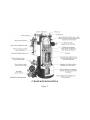
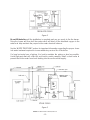
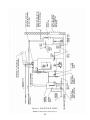
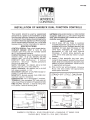
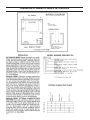
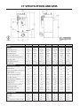
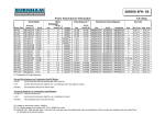
1
CT SERIES BOILERS
CT-6 CT-10 CT-15 CT-20
CT-25 CT-35 CT-50
INSTALLATION, OPERATION and
MAINTENANCE MANUAL
COLUMBIA BOILER COMPANY
POTTSTOWN, PENNSYLVANIA
CT BOILER WITH PARTIAL SECTION
Figure 1
Table Of Contents
PARTS WARRANTY . . . . . . . . . . . . . . . . . . . . . . . . . . . . . . . . . . . . . . . . . . . . . . . . . . . 2
SERVICE POLICY . . . . . . . . . . . . . . . . . . . . . . . . . . . . . . . . . . . . . . . . . . . . . . . . . . . . . 3
INSTALLATION . . . . . . . . . . . . . . . . . . . . . . . . . . . . . . . . . . . . . . . . . . . . . . . . . . . . . . 4
CLEANING AND FILLING A NEW STEAM BOILER . . . . . . . . . . . . . . . . . . . . . . . . . 11
OPERATING THE BOILER . . . . . . . . . . . . . . . . . . . . . . . . . . . . . . . . . . . . . . . . . . . . . .
STARTING THE BOILER . . . . . . . . . . . . . . . . . . . . . . . . . . . . . . . . . . . . . . . . . . . . .
STOPPING THE BOILER . . . . . . . . . . . . . . . . . . . . . . . . . . . . . . . . . . . . . . . . . . . . .
BURNER START UP AND TEST INFORMATION . . . . . . . . . . . . . . . . . . . . . . . . . . . .
SIDEWALL VENTING . . . . . . . . . . . . . . . . . . . . . . . . . . . . . . . . . . . . . . . . . . . . . . .
BOILER ROOM . . . . . . . . . . . . . . . . . . . . . . . . . . . . . . . . . . . . . . . . . . . . . . . . . . .
DESCRIPTION OF BOILER COMPONENTS . . . . . . . . . . . . . . . . . . . . . . . . . . . . . . .
12
13
13
15
16
19
21
MAINTENANCE . . . . . . . . . . . . . . . . . . . . . . . . . . . . . . . . . . . . . . . . . . . . . . . . . . . .
MAINTENANCE LOGS . . . . . . . . . . . . . . . . . . . . . . . . . . . . . . . . . . . . . . . . . . . . .
TESTING OF BOILER COMPONENTS . . . . . . . . . . . . . . . . . . . . . . . . . . . . . . . . . . .
WATER TREATMENT . . . . . . . . . . . . . . . . . . . . . . . . . . . . . . . . . . . . . . . . . . . . . . .
25
31
33
39
RETURN SYSTEMS . . . . . . . . . . . . . . . . . . . . . . . . . . . . . . . . . . . . . . . . . . . . . . . . . . . 42
BLOWDOWN SEPARATOR . . . . . . . . . . . . . . . . . . . . . . . . . . . . . . . . . . . . . . . . . . . . . 43
TROUBLESHOOTING . . . . . . . . . . . . . . . . . . . . . . . . . . . . . . . . . . . . . . . . . . . . . . . . . 44
APPENDICES . . . . . . . . . . . . . . . . . . . . . . . . . . . . . . . . . . . . . . . . . . . . . . . . . . . . . . . 45
Replacement Parts for CT Series Boilers
Panel Box - Inside View - Replacements Parts
Warrick Probe Assembly - Replacement Parts
Replacement Parts List for CT Series Boilers
Gas Train Piping Diagrams
Gas Train Components
Boiler Wiring Diagram
Safety Valve Piping, typical
Warrick Dual Function Controls
Warrick Series 3K Electrode Fittings
Warrick Probe Series 26 Controls
Tubular Gage Glasses - Use and Care
Danfoss Pressure Controls
Typical CT Boiler Piping Layout - Drawing PL-098
IMPORTANT
1.
Read and familiarize yourself with this installation, operation, and maintenance manual before installing, operating,
or servicing your boiler.
2.
All cover plates, enclosures, and safety devices must be
installed at all times except while performing maintenance
and service.
3.
Only trained
your boiler.
4.
All state and local codes take precedence over any recommendations given in this manual.
5.
NOTE: The CT Boiler is not designed for continuous, nonstop
operation. Normal burner cycling is required. Continuous operation will eventually damage the boiler, voiding the warranty.
6.
Wrapping the CT Boiler with insulation will cause the boiler to
overheat, voiding the warranty.
service
technicians
should
FM-148 COLUMBIA BOILER COMPANY, REV 6-06
-1-
do
any
work
on
LIMITED PARTS WARRANTY
The Columbia Boiler company (hereinafter Columbia) warrants the burner components and controls installed on its boiler/burner units to be free from defects in material and workmanship under
normal use and service for 12 months from the date of installation or 18 months from the date of
manufacture, whichever date occurs first, and is subject to warranty approval by the manufacturer of the specific components. This warranty does not extend to equipment subjected to misuse,
neglect, accident or improper installation. Equipment which is defective in material or workmanship and is removed within 12 months from the date of installation will be repaired or replaced as
follows:
a. Motors, fuel units, controls, and transformers should be sent for repair or replacement to an
authorized service point or distributor of the manufacturer of such component when reasonably available in Customer’s locality.
b. Where such local service is not available with respect to the above listed components, or
where other components are involved, such defective equipment should be returned after
receiving authorization from your dealer, freight prepaid, to the Columbia Boiler Co., 390
Old Reading Pike, Pottstown, PA 19464. The use of Columbia returned goods form is
mandatory when returning defective material.
c. Columbia is not responsible for any labor cost for the removal and replacement of equipment.
d. Equipment which is repaired or replaced will carry a warranty equal to the unexpired portion of the original equipment warranty.
e. If inspection by Columbia does not disclose any defect covered by this warranty, the equipment will be repaired or replaced at the expense of the Customer, and columbia’s regular
charges will apply.
THIS WARRANTY IS LIMITED TO THE PRECISE TERMS SET FORTH ABOVE, AND PROVIDES EXCLUSIVE REMEDIES EXPRESSLY IN LIEU OF ALL OTHER REMEDIES. ALL IMPLIED WARRANTIES, INCLUDING BUT NOT LIMITED TO ANY IMPLIED WARRANTY OF MERCHANTABILITY OR FITNESS FOR A
PARTICULAR PURPOSE OR USE, ARE EXCLUDED. IN NO EVENT WILL COLUMBIA BOILER CO. BE
LIABLE FOR ANY INCIDENTAL OR CONSEQUENTIAL DAMAGES OF ANY NATURE. Columbia neither
assumes nor authorizes any person to assume for columbia any other liability or obligation in connection with the sale of this equipment. Columbia’s liability and Customer’s exclusive remedy being
limited to repairs or replacement as set forth above.
FM-148 COLUMBIA BOILER COMPANY, REV 6-06
-2-
SERVICE POLICY
Anything mechanical will inevitably need servicing. Steam and hot water boilers are routinely serviced by the installer or another boiler maintenance company. Occasionally the
service technician may be unable to determine the cause of the problem. In this situation,
the dealer or service organization should contact the selling distributor for help.
Should the problem persist, the distributor will contact the sales representative for assistance. Depending on the extent of the problem, the representative may request technical
assistance from the factory.
If the problem cannot be resolved by the representative, he should contact the Technical
Service/Engineering Department at the factory. The sales representative will need the following information. We must insist that this information be available to assure prompt service.
Boiler Model and Size (HP) ______________________________________________________
Boiler Serial Number ___________________________________________________________
Boiler National Board Number __________________________________________________
Date Installed _________________________________________________________________
Burner Type and Model ________________________________________________________
Installer’s Name ____________________________________ Phone (_____) ______________
Address ______________________________________________________________________
Distributor’s Name __________________________________Phone (_____) ______________
Address ______________________________________________________________________
Sales Representative ________________________________ Phone (_____) ______________
Address ______________________________________________________________________
Specific Problem - Detailed
FM-148 COLUMBIA BOILER COMPANY, REV 6-06
-3-
INSTALLATION
The Columbia Model CT Steam Boiler is furnished completely piped, wired, and assembled. It has been factory tested and is ready for operation. This steam boiler is designed
to operate using No. 2 fuel oil and/or natural, manufactured, or liquid propane (LP) gas,
and to be powered by standard AC electrical service.
BEFORE BEGINNING INSTALLATION, CAREFULLY STUDY THESE INSTRUCTIONS AND ALL
CHARTS, DRAWINGS, AND DIAGRAMS SHIPPED WITH THE BOILER.
Installation must follow all state and local code requirements. The electrical installation must
be in accordance with the National Electrical Code.
CLEARANCES
The boiler is to be placed on noncombustible flooring, in an approved boiler room, with
the following clearances to combustible materials.
Underwriters Laboratories (UL) approved clearances:
Side:
Top:
Front:
Chimney connector:
18
18
48
18
inches
inches
inches
inches
Reduced clearance installation must follow the recommendations as outlined in NFPA-31.
Reduced clearance installations should be avoided if possible, as this will make it much
harder for qualified technicians to perform routine maintenance in and around your
boiler.
Clearances to noncombustible materials shall be in accordance with state and local codes.
In the absence of local codes, it is recommended that the above stated clearances be followed.
FLUE
The CT series boilers are pressure fired steam boilers, and need only to be properly vented. Consult the factory for proper venting of the boiler for any unusual conditions that may
exist at the job-site.
For boilers vented into a chimney, be certain the chimney is clean, and clear of obstructions. Connect the boiler flue outlet to the chimney using galvanized flue pipe. Refer to the
following list for proper size of the flue pipe. DO NOT REDUCE THE FLUE OR CHIMNEY SIZE
TO LESS THAN THE OUTLET SIZE ON THE BOILER. Consult the factory if the boiler must be
vented into a chimney that is smaller than the boiler outlet size. The flue pipe should be
pitched upward at least 1/4" per foot of run. Use only elbows and straight sections. Tees
FM-148 COLUMBIA BOILER COMPANY, REV 6-06
-4-
may be used in straight sections with a barometric draft regulator. Tees, however, should
not be used for a ninety-degree turn. Each joint should be securely fastened with sheet
metal screws. The flue pipe must not be inserted beyond the inside wall of the chimney.
Columbia Boiler approves the use of galvanized “B” type vent that is suitable for 550°F
stack temperature as proper and safe for this application, but any and all codes take precedence.
BOILER
PROPER FLUE
PIPE SIZE
CT-6
CT-10
CT-15
CT-20
CT-25
CT-35
CT-50
6"
6"
8"
8"
10"
12"
12"
GAS SUPPLY PIPING
Contact your local gas company to ensure that adequate gas service is available, and to
review applicable installation codes for your area.
The minimum gas supply pressure required by the burner is five inches water column for
the CT-6 and CT-10, and seven inches water column for the CT-15, CT-20, CT-25, CT-35
and CT-50. The maximum gas supply pressure to the burner is fourteen inches water column. Gas pressure greater than fourteen inches water column will require an additional
gas regulator to prevent damage to the primary gas regulator. Gas pressure below the minimum will cause combustion efficiency problems and should be avoided if possible. Low
gas pressure may also prevent the boiler from obtaining the desired input rate, which will
cause the boiler to be unable to produce the desired output. Consult the factory if your gas
supply pressure is not in the recommended range.
Use the following tables to determine the size of the main gas line required for the boiler
that is being installed. First determine the required input volume of gas needed at the gas
manifold, then determine the correct pipe size for the length of run needed.
FM-148 COLUMBIA BOILER COMPANY, REV 6-06
-5-
REQUIRED INPUT - CUBIC FEET OF GAS PER HOUR
GAS TYPE
CT-6
CT-10
CT-15
CT-20
CT-25
CT-35
CT-50
NATURAL
252
399
630
840
1050
1470
2100
PROPANE
101
160
252
336
420
735
840
CAPACITY OF PIPE - CUBIC FEET OF GAS PER HOUR
AT 0.2" W.C. PRESSURE DROP
Equivalent
Length (ft)
1"
1-1/4"
1-1/2"
2"
2-1/2"
3"
4"
10
425
725
1170
2360
4300
6250
12800
20
300
520
800
1700
3000
4500
9300
30
250
425
690
1400
2500
3750
7500
40
210
360
560
1200
2100
3200
6400
50
190
325
500
1100
1900
2850
5800
60
180
300
480
1000
1800
2300
4800
80
150
260
410
850
1550
2000
4200
100
135
230
370
750
1375
1680
3500
150
110
190
300
600
1100
1200
2750
200
75
165
260
540
950
1000
2000
Fitting
Equivalent Lengths of Standard Pipe in Feet for Listed Fittings
Std. Tee
5.5
7.5
9.0
12.0
13.5
15
20
Std. Elbow
2.7
3.7
4.5
5.5
6.1
8
11
Vent lines, if required, are to be run outside the building, stopping clear of windows or
fresh air intakes. The vent should terminate in a way that will not allow the possibility of
water, dirt, insects, animals, and other matter from entering and clogging the vent pipe.
Gas lines should be tested for leaks using a soap solution. Your gas company may wish to
witness this test. Do not exceed the maximum pressures allowed by the valve train.
Additional gas piping information is included in the burner section of this manual.
FM-148 COLUMBIA BOILER COMPANY, REV 6-06
-6-
OIL SUPPLY PIPING
Consult the burner section of this manual for oil line type and sizing requirements for proper operation. The size of oil lines is extremely important for proper operation. Suction vacuums must be held to acceptable limits.
All oil feed lines must be air tight. Use as few fittings as possible when assembling the oil
lines. The slightest air leak, usually caused by loose fittings or bad gaskets, can cause poor
starts, smoky starts, sooting of burner parts, inefficient operation, and a dangerous combustion condition.
A vacuum test should be done on all installation to ensure that all fittings are tight and the
oil lines are of proper size. Always use flare fittings instead of compression fittings on oil
service lines. Compression fittings allow more of a chance for air to be introduced into the
oil supply.
WARNING:
TEFLON® TAPE SHOULD NEVER BE USED WITH ANY OIL LINE CONNECTIONS. THE USE OF TEFLON® TAPE ON BURNER COMPONENTS OR OIL
SERVICE LINES WILL VOID MOST BURNER WARRANTIES.
For additional information consult the burner section of this manual.
ELECTRICAL SUPPLY
Connect the electric supply to the boiler and condensate return system as shown in the
wiring diagrams. Separate electrical services and disconnects must be provided for both
the boiler and the return system. If both 110 volts AC and 220 volts AC are needed, separate disconnects should be provided. The wiring must be installed in accordance with the
National Electrical Code and any other state and local codes.
All disconnects should provide overload protection to prevent injury to personnel or damage to equipment.
Be sure that the incoming voltages match that of the appliances before applying power.
Make a special point of checking the internal wiring of the blower motor as most motors
can be wired for either 110 or 220 volts.
FEEDWATER
Connect the feedwater supply from the condensate return tank to the boiler inlet feedwater connection. See Figure 2 and Piping Layout PL-098 in Appendix. Columbia Boiler
Company provides one spring type check valve in the feedwater piping. An additional
swing type check valve should be installed in the feed line as close to the pump as possible. These valves should be piped in the horizontal position.
Do not use the pump as a piping support. It is very important that the piping be independently supported at the pump.
FM-148 COLUMBIA BOILER COMPANY, REV 6-06
-7-
FEEDWATER PIPING
Figure 2
Do not fill the boiler until the installation is complete and you are ready to fire the burner.
Firing the burner will then boil the water which will drive off the dissolved oxygen in the
water and help maintain the proper boiler water chemical balance.
See the WATER TREATMENT section for important information regarding the proper chemical water treatment required to insure satisfactory service life of the boiler.
On long horizontal runs of piping, it is best to maintain the piping as level as possible.
Avoid high spots that will collect air and lead to erratic pumping. Install a check valve to
prevent the boiler water from back feeding into the service water supply.
STEAM PIPING
Figure 3
FM-148 COLUMBIA BOILER COMPANY, REV 6-06
-8-
STEAM OUTLET
Connect the field steam piping to the outlet on top of boiler. See Figure 3. If a main steam
manifold is used, it should be pitched 1/4" per foot of horizontal run so that condensate
will run into a steam trap, rather than back into the boiler. All steam supplies should be
taken off the top of the manifold to prevent condensate from entering the process machines.
SAFETY VALVE
Safety valves should be piped so that they cannot discharge on people or damage property. The discharge piping must be supported so that the weight of the piping is not transmitted to the safety valve body. Refer to drawing PL-049 in the Appendix for an example
of typical safety valve piping. the weight supported by the valve outlet should not exceed
the weight of a drip pan elbow. Use only Schedule 40 pipe for discharge piping. DO NOT
USE Schedule 80, extra strong, or double extra strong discharge pipe or connections.
Installations requiring long discharge piping should not be connected directly to the safety valve.
During installation, be sure that pipe compound or tape is used only on external threads
and that the inlet of the valve is free of any foreign material.
DO NOT USE A PIPE WRENCH when working on the safety valve. use only the proper type
and size wrench.
WARNING:
NEVER REDUCE THE INLET OR OUTLET SIZE OF THE SAFETY VALVE;
NEVER HANG PIPING ON THE SAFETY VALVE;
NEVER INSTALL VALVES(S) IN THE SAFETY VALVE PIPING;
NEVER PLUG THE BONNET VENT. SERIOUS DAMAGE OR INJURY
COULD RESULT FROM THE FAILURE OF THE SAFETY VALVE.
BLOWDOWN PIPING
Connect the boiler, the Warrick Low Water cut Off, and sight glass blowdown lines in
accordance with local code requirements. See Figure 4. the blowdown must be piped to
a safe place of discharge to prevent injury to personnel or property damage.
It is recommended that a blowdown tank be used to safely discharge the blowdown into
the sewers. Check state and local codes concerning the maximum allowable temperature
for blowdown entering public sewer systems.
All valves, piping, and forged fittings used n the blow-down lines shall be, of suitable rating, and in accordance with ASME Code B31-Power Piping. All pipe nipples used shall
be Schedule 80 pipe.
WARNING: NEVER REDUCE THE VENT SIZE OF THE BLOWDOWN TANK.
To properly and safely blow down the boiler, the vent must be piped full size for the entire
length, and must terminate at a safe place of discharge per local codes.
FM-148 COLUMBIA BOILER COMPANY, REV 6-06
-9-
Figure 4
BLOWDOWN PIPING
FM-148 COLUMBIA BOILER COMPANY, REV 6-06
- 10 -
CLEANING AND FILLING A NEW STEAM BOILER
In order to minimize the corrosive effects of raw water oxidation on the boiler, the water
must be heated to at least 180°F immediately after entering the boiler, in order to drive off
the corrosive dissolved gases. This applies to all water - whether from a well, a spring, or
from the local municipal water system.
The oil and grease that accumulate in a new steam boiler can usually be washed out by
boiling as follows:
1. Fill the boiler to the normal waterline.
2. Provide a boil-out compound of caustic soda and trisodium phosphate in the proportions of 2-1/2 lbs. of each chemical per 120 gallons of water.
CAUTION: USE CARE IN HANDLING THESE CHEMICALS. THE CAUSTIC
SODA IS EXTREMELY CORROSIVE TO SKIN AND CLOTHING. DO
NOT PERMIT EITHER THE DRY MATERIAL OR THE CONCENTRATEED SOLUTION TO CONTACT SKIN OR CLOTHING.
3. Mix the chemicals with water and pour into the boiler through any convenient
opening in the boiler.
4. Start the firing equipment.
5. Boil the water for at least five hours.
6. Stop the firing equipment.
7. Drain the boiler to a location where hot water can be discharged safely.
8. Wash the boiler thoroughly using a hose with sufficient pressure.
9. Fill the boiler to the normal waterline.
10. Add boiler water treatment as prescribed by a water treatment specialist.
11. Boil or bring water temperature to at least 180°F immediately.
12. The boiler is ready to put into service or on standby.
BOILER
MODEL
CT-6
EQUAL AMOUNTS
CAUSTIC SODA AND
TRISODIUM PHOSPHATE
5 1/3 oz.
CT-10
8 oz.
CT-15
12 oz.
CT-20
1 lb.
CT-25
1 lb. 4 oz.
CT-35
1 lb. 14 oz.
CT-50
4 lbs. 9 oz.
FM-148 COLUMBIA BOILER COMPANY, REV 6-06
- 11 -
OPERATING THE BOILER
NOTE: Although your new Columbia Boiler has been test fired at the factory, it must be
“set up” for the conditions at your location. Improper combustion settings may
cause the burner to operate erratically, resulting in boiler shutdowns, lost time,
and unnecessary service expenses.
PRE-START CHECKS AND INFORMATION
A new or relocated boiler should not be put into service until it has been inspected by an
authorized inspector for the jurisdiction or the insurance company, and the required certificates have been issued.
Whenever a new boiler is placed in service, operating data should be recorded and saved
for future reference. This information is extremely valuable for diagnosing problems if
abnormal operation occurs. Record all operating parameters such as pressures, stack temperatures, oxygen or carbon dioxide levels, flows, draft, motor amps, damper positions,
and interlock set points. A burner start up and test information sheet has been included at
the end of this section for your convenience.
The Gauge Glass Protector must be properly installed prior to operating the boiler, and all
cover plates, enclosures, and safety devices must be installed at all times except while performing maintenance and service.
The fuel supply should not be turned on until the combustion chamber has been vented and
the pilot light (if gas ignited) checked for proper operation.
All blowdown valves, including water column drain valves, gauge glass drain valves, and
gauge cocks should be closed.
The safety valves should be inspected externally to see that they are free to operate, and
that the discharge piping and drain piping are open to the atmosphere, and free to
expand without imposing a load on the safety valve bodies. Make sure the safety valve is
piped to a safe location to prevent injury.
The boiler feed pump(s) should be checked to ensure that they are ready for service. Check
the data on rating plates of all electrical equipment to be certain the electrical characteristics match those of the electric supply to which they are connected.
All Columbia boiler company CT Series boilers are test fired at the factory, however, before
attempting start-up, carefully study the instructions included in the burner section of this
manual.
It is important to have the proper test equipment in order to adjust the combustion and pilot
if equipped. Those items that may be required include a manometer, microammeter, vacuFM-148 COLUMBIA BOILER COMPANY, REV 6-06
- 12 -
um gauge, 0-300 PSI pressure gauge, carbon dioxide or oxygen analyzer, carbon monoxide tester, smoke gun, and stack thermometer.
STARTING THE BOILER
WARNING:
NEVER OPERATE A BOILER WITHOUT BEING SURE IT IS FILLED WITH WATER
AND THAT PROPER WATER TREATMENT CHEMICALS HAVE BEEN ADDED.
Open the feedwater valve and turn on the main disconnect for the condensate pump. the
pump should come on and fill the boiler to its normal operating level.
Turn the boiler disconnect switch to the ON position.
NOTE:
The burner will not operate when the boiler has reached its normal water level,
until the reset button on the secondary, probe type, low water cut-off is pushed.
Push the RESET button on the Control panel Cover. The burner should start.
NOTE:
Combustion efficiency must be checked at this time. See the burner manufacturers
instructions for correct settings and more detailed information.
Follow the adjustment procedures outlines in the burner section of this manual to set up the
burner for proper operation.
NOTE:
New CT boilers will normally expel a vapor from joints and openings in the
jacket. This is a temporary condition, caused by moisture evaporating out of the
refractory insulation behind the jacket, and will eventually disappear.
STOPPING THE BOILER
To stop the boiler turn the main disconnect to the OFF position.
FM-148 COLUMBIA BOILER COMPANY, REV 6-06
- 13 -
GAS BURNERS
BURNER
NATURAL GAS
ORIFICE SIZE AND
ORIFICE PRESSURE
(INCHES WATER OCLUMN)
LIQUID PROPANE GAS
ORIFICE SIZE AND
ORIFICE PRESSURE
(INCHES WATER COLUMN)
CT-6
POWER FLAME
JR15A-10
5/16 (.313) / 3.5"
“D”(.242) / 3.5"
CT-10
POWER FLAME
JR15A-10
3/8 (.375) / 3.5"
19/64 (.297) / 3.5"
CT-15
POWER FLAME
JR15A-10
15/32 (.469) / 3.5"
“T”(.358) / 3.5"
CT-20
POWER FLAME
JR30A-12
9/16 (.563) / 3.5"
15/32 (.469) / 3.5"
CT-25
POWER FLAME
JR30A-12
23/32 (.719) / 3.5"
1/2 (.500) / 3.5"
CT-35
POWER FLAME
JR50A-15
11/16 (.688) / 3.5"
19/32 (.594) / 3.5"
CT-50
POWER FLAME
JR50A-15
BOILER
MODEL
None
x
3.5"
25/32
x
3.5"
INLET GAS PRESSURE
Inlet gas pressure to the main gas valve should be between seven and fourteen inches
water column.
If the inlet gas pressure exceeds fourteen inches water column, the pilot regulator and main
gas regulator will “lock up” and become inoperative, and damage may occur. Inlet gas
pressure above fourteen inches water column will require an additional pressure reducing
valve.
If the inlet gas pressure is below seven inches water column the burner may not be capable of the rated boiler output. If the gas pressure is below seven inches water column contact your local gas company. If the local gas company is unable to help, contact the factory for assistance.
FM-148 COLUMBIA BOILER COMPANY, REV 6-06
- 14 -
BURNER START UP AND TEST INFORMATION
For a new boiler start up, or for troubleshooting an existing installation, the following information is essential for effective service assistance.
Boiler Model__________________ Serial No.______________ N.B. No._______________
Burner Model_________________ Invoice No._____________ Serial No.______________
Installation Name______________________________________ Start Up Date____________
Start Up Contractor____________________________________ Phone No.______________
Name of Technician Performing Start Up__________________________________________
Fuel Type: q Natural Gas q LP Gas q Fuel Oil (#2) q Other_____________________
Gas Firing
Gas Pressure At Train Inlet
Burner in Off Position________"W.C.
Flame Signal Readings
Pilot____________________________
Stack Outlet Test Point Draft
High Fire __________________"W.C.
Gas Pressure At Train Inlet
High Fire__________________"W.C.
CO2
High Fire________________________
Over Fire Draft
High Fire __________________"W.C.
Gas Pressure At Main Orifice
High Fire__________________"W.C.
CO
High Fire________________________
Net Stack Temperature
High Fire______________________°F
Gas Pressure At Pilot Orifice
__________________________"W.C.
Measured INput Rate - BTU/HR
High Fire __________________"W.C.
Gas Pressure At Pilot Orifice
__________________________"W.C.
High Fire Vacuum Reading At Oil
Pump Inlet__________________"H.G.
CO2
Low Fire ________________________
High Fire________________________
Stack Outlet Test Point Draft
Low Fire___________________"W.C.
High Fire__________________"W.C.
Oil Nozzle Supply Pressure
Low Fire______________________PSI
High Fire_____________________PSI
Bachrach Scale Smoke Number
Low Fire ________________________
High Fire________________________
New Stack Temperature
Low Fire______________________°F
High Fire_____________________°F
Firing Rate - GPH
Low Fire________________________
High Fire_______________________
Over Fire Draft
Low Fire___________________"W.C.
High Fire __________________"W.C.
Oil Firing
Operational Check of Controls
Operating Limit_________________q
Aux LWCO ____________________q
Flame Safeguard _______________q
Safety Limit____________________q
Low Gas Pressure ______________q
Ignition Failure q
Low Water Cut Off______________q
High Gas Pressure ______________q
Flame Failure q
Comments
________________________________________________________________________________________________________
________________________________________________________________________________________________________
________________________________________________________________________________________________________
________________________________________________________________________________________________________
________________________________________________________________________________________________________
________________________________________________________________________________________________________
________________________________________________________________________________________________________
FM-148 COLUMBIA BOILER COMPANY, REV 6-06
- 15 -
OPTIONAL SIDEWALL VENTING (and Combustion Air intake)
Installation Instructions
General
This section provides instructions for the installation of UL listed Gas-Fired Boiler Assemblies
with Side Wall Venting and Combustion Air intake Assemblies, MEA number 15-95-E.
While the instructions and suggestions set forth in this manual are safe and proper, it is the
responsibility of the installer and the owner to assure adherence to all local codes.
Equipment (Available with Power Flame Burners Only)
Note: All Columbia boilers ordered for Sidewall Venting will be provided with a
Combustion Air Intake Adapter.
CT-6 Boiler with Power Flame JR15A-10 Burner
CT-10 Boiler with Power Flame JR15A-10 Burner
CT-15 Boiler with Power Flame JR15A-10 Burner
CT-20 Boiler with Power Flame JR30A-10 Burner
CT-25 Boiler with Power Flame JR30A-12 Burner
CT-35 Boiler with Power Flame JR50A-15 Burner
BOILER MODEL
VENT SIZE
DIAMETER (INCHES)
INTAKE SIZE
DIAMETER (INCHES)
CT-6
6
6
CT-10
6
6
CT-15
8
6
CT-20
8
6
CT-25
10
6
CT-35
12
8
CT-50
NOT UL OR MEA APPROVED FOR THIS OPTION
Vent Caps
Use only UL listed vent caps for the combustion vent termination and the combustion air
intake. The following vent cap model is shipped with your boiler when the direct vent
option kit is ordered.
Heat-Fab Incorporated
38 Haywood Street
Greenfield, MA 01301
(800) 772-2356
“Saf-T CI Vent Rain Cap”
FM-148 COLUMBIA BOILER COMPANY, REV 6-06
- 16 -
Installation
The Columbia Model CT Direct Vent Series Steam Boiler is furnished completely piped,
wired, and assembled. It has been test fired at the factory and is ready for installation. This
steam boiler is designed to operate with natural gas, and is suitable for standard AC electrical service. The CT Series requires the following minimum clearances to combustible
material: top, sides, and rear - 18", front - 36", flue vent duct - 18".
Location
The CT boiler must be mounted on a level non-combustible floor, or the floor must be protected in accordance with the requirements of accepted building code practices. In the
absence of local codes, it is suggested that NFPA-31 section 4-4.1.5 be followed.
Flue Vent Duct
For direct venting, galvanized smoke pipe is acceptable, but local codes take precedence.
The maximum length of flue vent duct allowed is 40 feet, and at no time can the diameter
of the flue vent duct be less than the diameter of the smoke outlet of the boiler, see Table
on the previous page for size. The flue pipe should be sloped upward 1/4" per horizontal foot of run. All sections of flue pipe should be joined and fastened securely with sheet
metal screws. The maximum number of 90° elbows in the flue vent duct is four. A barometric swing type draft regulator may be installed in the flue vent duct if desired, but is not
necessary.
The vent must end with the UL listed vent cap that was shipped with your boiler. the vent
cap can be installed either horizontally (Figure 5-A below) or vertically with a tee (Figure
5-B below). It is suggested that a screen or vent pipe plug be inserted into the bottom of
the tee to prevent animals and other matter from entering.
Figure 5
FM-148 COLUMBIA BOILER COMPANY, REV 6-06
- 17 -
All through the wall connections must adhere to safety standards set forth by standard
building practices and local codes. In the absence of local codes, UL listed wall thimbles
and through the wall connectors should be used.
The combustion vent cap must extend a minimum of four feet from the building, and must
be located as far from the combustion air intake as possible. The combustion vent must terminate a minimum of seven feet above the ground where pedestrian traffic can be expected. It shall also terminate at least three feet above any forced air inlet within ten feet, and
shall terminate at least four feet below or four feet horizontally from, or one foot above and
two feet horizontally from, any door, window, or gravity air inlet into any building as provided in the National Fuel Gas Code NFPA 54. See Figure 6. Both the Combustion Flue
Vent and the combustion Air Intake must be in the same wall.
COMBUSTION VENT LOCATIONS
Figure 6
Combustion Air Intake
The air for combustion must be ducted directly to the burner intake and must terminate outside with the applicable Intake Air cap listed in the Table on page 15. The vent cap can
be installed either horizontally or vertically in conjunction with a tee. It is suggested that a
screen or vent pipe plug be inserted into the bottom of the tee to prevent animals and other
matter from entering. The maximum length of combustion air intake duct shall be 40 feet.
The combustion air intake shall be full size for the complete run and shall not have more
than four 90° elbows. The combustion air intake cap must be at least one foot off the
ground in an area that is always free from obstructions. The Combustion Air Intake must
be in the same wall as the Combustion Vent.
Important Note: Surface discoloration of the building may occur due
to improper boiler/burner adjustment and maintenance. Columbia
Boiler Company will not accept any liability for such discoloration.
FM-148 COLUMBIA BOILER COMPANY, REV 6-06
- 18 -
BOILER ROOM
Lighting
The boiler room should be well lighted and should have a source of emergency lighting. If
a flashlight is used for this purpose, it should be maintained in usable condition, and it
should not be removed from the boiler room.
Care should be taken to prevent bright, direct sunlight from shining on the burner, as the
flame sensing controls may receive a false flame signal.
Water Supply and Drain Connections
Convenient water supply connections for flushing the boiler and cleaning the boiler room
floor should be installed.
Unobstructed floor drains, properly located in the boiler room floor, will aid in the proper
cleaning of the boiler room.
Make-up Air
The burner must have adequate air supply, which must be kept clear at all times. Do not
run exhaust fans in the immediate proximity of the boiler room, as they will cause a reversal of draft at the burner. Ensure that sufficient make-up air is available, even if that requires
a window to the outside to be left open. This air is necessary to insure complete combustion, a clean fire, and to prevent nuisance shutdowns due to excessively dirty burner parts.
Air from the outside may be provided through ducts, fixed louvers, or motorized louvers.
WARNING:
WITHOUT SUFFICIENT MAKE-UP AIR, THE BOILER WILL NOT OPERATE
PROPERLY, AND BURNER COMPONENT DAMAGE COULD OCCUR.
To calculate the required fresh air opening to the outside, allow 21 square inches for every
boiler horsepower. For example a 10-horsepower boiler would require two hundred and
ten square inches of free opening. This is equal to a 15" x 15" square hole, or a 18" diameter round hole of free, unrestricted area. If louvers or screens are used, contact the manufacturer for percentages (typically around 40%) that must be added to allow for restriction.
The following table can be used to size the amount of free area needed for the various
sizes of CT boilers. A point to remember for round openings - two 10" round openings DO
NOT equal one 20" round opening. Four 10" round openings are needed to obtain the
same amount of free area.
Columbia Boiler Company will not be held liable for damage to the
boiler or burner components caused by insufficient burner make up
air.
FM-148 COLUMBIA BOILER COMPANY, REV 6-06
- 19 -
REQUIRED BOILER MAKE-UP AIR
(HORSEPOWER)
BTU
INPUT
OPENING
MIN. SQUARE
INCHES
SQUARE HOLE
SIZE - INCHES
ROUND PIPE
SIZE - INCHES
(APPROXIMATE)
(APPROXIMATE)
6
252,000
126
12 X 12
14
9.5
399,000
210
15 X 15
18
15
630,000
315
18 X 18
20
20
840,000
420
2 X 21
24
25
1,050,000
525
23 X 23
26
35
1,470,000
735
28 X 28
32
50
2,100,000
1050
33 X 33
38
BOILER SIZE
Housekeeping
Provide adequate space around the boiler for inspection and service. Do not allow the
boiler room to become a storage room.
Fire protection apparatus, and fire prevention procedures for boiler room areas shall
conform to the recommendations of NFPA and all local codes.
WARNING:
DO NOT STORE OR USE GASOLINE OR ANY OTHER FLAMMABLE LIQUIDS
AND VAPORS IN THE VICINITY OF THE BOILER OR BOILER ROOM.
FM-148 COLUMBIA BOILER COMPANY, REV 6-06
- 20 -
DESCRIPTION OF BOILER COMPONENTS
Refer to the drawings in this manual for the location of the following listed components.
See Table of Contents for location of applicable drawing and/or specification sheet.
PANEL BOX WITH WARRICK SERIES 3K ELECTRODE FITTING
The standard control circuit for the CT Series Boilers consists of probe type, primary and
secondary low water cut off and pump controls enclosed in a panel box; and typical operating and safety limit pressure controls. The standard water column consists of the Warrick
Series 3K Electrode fitting which houses the three probes used for the primary low water
cut off and pump control, the Honeywell L404A Operating Pressure control, the Honeywell
L404C Safety Limit Pressure Control, and a 0-300 psi pressure gauge.
DESCRIPTION OF PANEL BOX COMPONENTS
Warrick Series DF (Dual Function)
The boiler water level control consists of the Warrick Series DF (Dual Function) combination
low water cut-off and pump control. The Series DF handles two separate level functions, one
differential, and one single level, using probes and contactors. The differential function uses
a low probe (L) and high probe (H) to operate the pump. When the water level in the boiler drops below the level of the low probe, the normally closed contact is energized, which
in turn supplies power to the pump motor contactor/starter, causing the pump to feed water
to the boiler. The “PUMP ON” light will also come on. As the pump raises the level in the
boiler and the water makes contact with the high probe, the contactor is de-energized,
breaking the circuit, stopping the pump and turning off the “PUMP ON” light.
If the pump or water supply should fail, and the water level in the boiler continues to fall
below the Low Level Cut Off (LLCO) probe, the second contactor de-energizes the normally closed contact, shutting off power to the burner, and energizes the normally open contact, turning on the “LOW WATER” light and/or an optional low water alarm bell.
The three probe lengths in the Series 3K are:
A - High Probe
6.0"
B - Low probe
7.5"
C - LWCO Probe
9.0"
Boilers built before September 2006 will have 2" longer probes.
The Warrick Series DF Control will reset automatically after a Low Water Cut Off. If preferred, a normally closed, Manual Reset push button is available as an option.
Electrical contact ratings for the Warrick Series DF Control are 10 amps at 120 volts.
Motor contactor or Starter
A Motor contactor or Starter is provided to take the high amperage electrical load off the
FM-148 COLUMBIA BOILER COMPANY, REV 6-06
- 21 -
pump motor switches of the Warrick Series DF Low Water cut Off and Pump Control. A
Motor Starter also provides electrical overload protection for the feedwater pump motor.
A Motor Contactor is provided as standard equipment on the CT-6 thru CT-25 Boilers, and
a Motor Starter is provided as standard equipment on the CT-35 and CT-50 Boilers.
Warrick Series 26 Probe Type Low Water Cut-Off
The manual reset “probe” is used as a supplementary safety device for protecting the boiler against damage from low water. It is designed to operate if the Series DF low water cutoff should fail to operate for any reason. This unit is set to operate at a water level in the
boiler lower than that of the Warrick Series DF. See drawing CT-415 in the appendix for
installation of probe rod.
This unit consists of a circuit board design with one normally open (N.O.) non-powered
contact. When reset, it completes a circuit between the probe rod and the boiler drum,
through the water in the boiler. If the water level falls below the probe rod, the circuit is
broken causing the contact to open, breaking the circuit to the burner and energizing an
alarm circuit (if equipped).
NOTE:
This relay must be reset after a low water condition has been corrected or after
any interruption in the electrical supply.
DESCRIPTION OF OPERATING CONTROLS AND SAFETY DEVICES
Operating Pressure Control
The operating pressure consists of a pressure actuated switch with an adjustable differential. This switch opens on pressure rise. It should be set at the maximum operating pressure
desired. Do not set the operating pressure higher than 135 PSI. the differential determines
when the burner will restart. The differential should be set at a value as large as possible
to keep the unit from short cycling.
The pressure control must be level in order to operate accurately. It is level when the leveling indicator hangs freely with its pointer directly over the index mark inside the back cover
of the case.
The upper operating or cut-off pressure is determined by the main scale set point, while the
lower operating or cut-in pressure is determined by the main scale operating point minus
the differential.
Adjust the main scale set point for the desired operating pressure by turning the main scale
adjusting screw on top of the case until the main scale setting indicator is at the desired
pressure. Adjust the differential set point for the desired cut in pressure by turning the
adjusting screw on top of the case until the differential setting indicator is at the desired
setting.
FM-148 COLUMBIA BOILER COMPANY, REV 6-06
- 22 -
Safety Limit Pressure Control
The Safety Limit operates essentially the same as the pressure control described previously
except this limit is equipped with a reset button and does not have a differential. The purpose of the Safety Limit is to shut down the burner if the operating pressure control becomes
inoperable and steam pressure continues to climb. The burner will not start until the situation is corrected and the reset button is pushed. The high limit of the Safety limit must be
set above the operating pressure control setting.
Adjust the main scale set point about 20 PSI higher than the operating pressure control by
turning the main scale adjusting screw on top of the case until the main scale setting indicator is at the desired pressure.
There are a number of pressure controls that may be used interchangeably. Please see
additional information in the manual appendices.
Safety Valve
Safety valves shall be piped so that any discharge cannot cause injury to people or damage to property. The discharge piping must be supported so that the weight of the piping
is not transmitted to the safety valve body. The weight supported by the valve outlet should
not exceed that of a drip pan elbow. Installations requiring long discharge piping should
not be connected directly to the safety valve. Refer to Drawing PL-049 in the Appendix.
In order to achieve the topmost performance and maximum safety valve life, maintain a
proper operating gap between the set pressure of the safety valve and the maximum operating pressure of the boiler.
The minimum recommended operating gap for this valve is 10%, but at no time less than
7 PSI. Under no circumstances should this gap be less than 7 PSI or seat leakage can
occur. Failure to maintain this operating gap can result in an accumulation of deposits on
the seating surface that may impede proper operation of the safety valve.
If the valve discharges on its own, contact a qualified service technician to determine the
cause. This may be an indication of equipment or system malfunction.
Gauge Glass Protector
The gauge glass protector is provided to guard against personnel injury and component
damage in the event of a breakage of the sight glass. The gauge glass protector must be
properly installed prior to operation of the boiler.
FM-148 COLUMBIA BOILER COMPANY, REV 6-06
- 23 -
DESCRIPTION OF OPTIONAL EQUIPMENT
Manual Dual Pressure (Optional)
A toggle switch is provided in conjunction with an additional Pressuretrol to manually
change from a high operating pressure to a low operating pressure. See wiring diagrams
enclosed.
Manual Reset Pushbutton (After Low Water Cut off) (Optional)
A normally closed, Manual Reset Pushbutton and Control Board is available. This pushbutton, when installed, must be pressed and held for 10 seconds to start burner operation
after a low water condition has been corrected.
Time Control (optional)
A seven-day time clock, when furnished, provides Automatic Dual Pressure or Automatic
Off/On Operation, whichever is desired. An adjustable time switch makes one circuit and
breaks another simultaneously at as many intervals every 24 hours as required. See wiring
diagrams enclosed.
When used for On/Off operation, one side of the circuit is connected in series with the
pressure control. The other side is not used. On dual pressure operation an additional pressure control is connected in series, on one side of the time switch.
FM-148 COLUMBIA BOILER COMPANY, REV 6-06
- 24 -
MAINTENANCE
RECORD KEEPING
All manufacturers’ literature, spare parts lists, operating and maintenance procedures
should be maintained in the boiler room at all times. A log book should also be provided
to record maintenance work, inspections, and other performance test results.
General
Clean the boiler and heating surfaces whenever required. The frequency of the cleaning
required to maintain the boiler at peak efficiency will be determined only by frequent
inspections. It cannot be predicted. Your operating conditions might be different from your
neighbors. When in doubt - check it out.
WARNING:
DISCONNECT ALL INCOMING ELECTRICAL POWER BEFORE SERVICING THE
BOILER. USE EXTREME CAUTION AROUND BOILER PIPING AND THE WARRICK SERIES DF LOW WATER CUT OFF SINCE THEY MAY BE VERY HOT.
The life of your boiler will be determined by the level of care given it by those who are
responsible for maintenance. A log of the following items should be maintained in the boiler room at all times.
Daily Boiler Check & Maintenance List
1. Water Level Controls and Cut Offs are operating normally.
2. Instrument and equipment settings are normal.
3. Gauge glass is clean and protector is installed. If leaks are detected, replace glass,
gaskets, and brass washers immediately. When replacing gauge glass use only
5/8" O.D. x 10-1/4" long Pyrex red line, high pressure, high temperature, glass
tubing, with fire polished ends. See gauge glass maintenance section for proper
method when installing this gauge glass.
4. Boiler water at proper operating level.
5. Blow down boiler as instructed under BLOWDOWN.
6. Blow down probe type low water cutoff.
Weekly Boiler check & Maintenance List
1. Check flame failure detection system.
A. Gas boilers: Close fuel supply to pilot and main gas and check shut down
timing.
B. Oil boilers: Remove cad cell leads and check shut down timing.
2. Check fuel valves; Open limit switch and make aural and visual check.
3. check ignition system flame signal.
FM-148 COLUMBIA BOILER COMPANY, REV 6-06
- 25 -
Monthly Boiler Check & Maintenance List
1.
2.
3.
4.
5.
Test all fan interlocks.
Check main burner safety shut off valve(s) for operational closure.
Oil fired; check fuel pressure interlocks when provided.
Gas fired; check high and low fuel pressure switches.
Flue or stack dampers; make visual inspection for proper operation.
Semiannual Boiler Check & Maintenance List
1. Inspect burner components; Refer to burner manufacturers’ instructions.
2. Check the flame failure system components; Refer to the burner section of this
manual.
3. Check piping and wiring of all interlocks and shut off valves.
4. Internal boiler plate inspection. Remove hand-hole assemblies; use new gaskets
when replacing covers.
Annual Boiler Check & Maintenance List
1.
2.
3.
4.
5.
6.
7.
8.
9.
10.
11.
12.
Check operating Pressuretrol.
Check high limit Pressuretrol.
Test safety valves.
Remove the Warrick Series DF Low Water Cut Off and clean inside casting.
Oil fired - clean/replace oil filters or strainers if equipped.
Oil fired - replace ignition electrodes if equipped.
Gas pilots - conduct pilot turndown test.
Gas fired - replace ignition and flame rods.
Gas fired - check drip leg/strainer.
Oil fired - check for refractory hold in.
Check Automatic Change Over Control if equipped.
Gas fired - perform valve leakage test.
FM-148 COLUMBIA BOILER COMPANY, REV 6-06
- 26 -
Gauge Glass
The water gauge glass must be kept clean. Dirt on or in the glass may be mistaken for the
water level. Do not allow steam or water to leak from the water glass, as this may effect
the accuracy of the level indication. Leaking of the gauge glass will also reduce the wall
thickness of the glass to the point where it may explode.
WARNING:
DO NOT OPERATE THE BOILER WITHOUT THE GAUGE GLASS PROTECTOR
INSTALLED. NEVER ATTEMPT TO WORK ON THE GAUGE GLASS WHILE THE
BOILER IS UNDER PRESSURE. ALWAYS CLOSE GAUGE VALVES PRIOR TO
TIGHTENING GASKETS ON WATER LEVEL GAUGE GLASS. SERIOUS INJURY
COULD RESULT.
Gauge Glass Replacement Instructions:
1.
2.
3.
4.
5.
6.
7.
8.
9.
10.
Make absolutely certain that the new water level gauge glass is 5/8" o.d. x 101/4" long Pyrex red line, high pressure, high temperature glass tubing with fire
polished ends.
Close gauge glass valves.
Remove gauge glass protector.
Remove the old glass, gaskets, brass washers, and brass nuts. Be sure threads on
the gauge valves are clean.
Install brass nuts, brass washers, and gaskets on each end of the gauge glass.
Insert glass tub into top gauge valve and lower the glass tube into the bottom
gauge valve which contains a seat. Then raise glass 1/16". Do not allow glass
to rest directly n the valve.
Hand tighten the lower glass nut and then the upper nut. While tightening these
nuts, be sure to keep the red line opposite the viewing side.
With a wrench, snug up the bottom nut and then the top nut.
Replace gauge glass protector. Open gauge glass valves fully. Failure to completely open the gauge glass valves renders the ball check safety feature inoperative.
Without pressure on boiler and with gauge valves closed, tighten gaskets again
after 1 day of operation.
Blowdown
Blowing down the boiler is done to remove excess total dissolved solids. The actual amount
of blowdown should be determined through boiler water analysis, done by a water treatment specialist. Until an analysis of your boiler water is made, the following guidelines
should be used.
Blow down should be done in the evening after firing equipment has been shut down for
approximately 20 minutes and at a pressure between 20 and 40 psi. some pressure must
be left on the boiler for proper blow down. Important: Boiler water must be settled for
proper blowdown.
FM-148 COLUMBIA BOILER COMPANY, REV 6-06
- 27 -
Blowdown Instructions
To blow down the boiler, open the slow opening (“Y” type) blowdown valve first. Open
boiler blowdown ball valve for 30 seconds then close. Use this same procedure with the
low water cut off blowdown ball valve. then go back to the boiler blowdown valve, open
and close the valve, very fast, two more times. Repeat this procedure with the low water
cut off valve. This will rid the boiler of most precipitated sediment. DO NOT EMPTY THE
BOILER OF ALL ITS WATER.
The Warrick Series DF Low Water cut Off & Pump Control should be blown down at least
once each day when the boiler is in operation. This is essential to flush accumulation of
sediment from the float chamber. Failure to do so will result in the failure of the control to
shut off the burner on low water. During the blowdown operation, check to see that all of
the control probes are operating properly. To check operation of the probes, open the
blowdown valve while the burner is in operation. When the water level drops, the alarm
circuit should close and sound the alarm (if alarm is installed) and the burner should stop
firing.
Hand Hole Gasket Replacement
Part number 480210 (fits all models)
Remove the old gasket and thoroughly clean the basket surfaces inside the boiler and on
the hand hole surfaces. A thin wire or a piece of string tied to the hand hole casting will
help prevent “losing” the casting in the boiler when removing or installing gaskets.
Place the new gasket on the hand hole making sure that it fits evenly all the way around.
The use of adhesive on the plate gasket is recommended in order to hold the gasket in
place while installing the assembly in the boiler.
PROPER PRESSURE ON GASKET OF HANDHOLE PLATE
Figure 7
FM-148 COLUMBIA BOILER COMPANY, REV 6-06
- 28 -
Install the plate assembly in the boiler, evenly spaced as possible. Set the yoke over the
bolt, install the nut and make it hand tight to keep the plate from moving.
Using the correct size socket wrench, tighten the nut one quarter turn. See Figure 7. If the
gasket leaks while the pressure is being brought up on the boiler, tighten the nut only
enough to stop leaking. See Figure 8.
Check the gaskets for leakage for the next three days after installation and if leakage is
detected tighten only enough to stop it.
WARNING:
EXCESSIVE TIGHTENING WILL FLATTEN OUT THE GASKETS TO A POINT
WHERE THEY WILL NO LONGER BE ABLE TO SEAL. DO NOT TIGHTEN MORE
THAN IS REQUIRED TO SEAL
IMPROPER PRESSURE ON GASKET OF HANDHOLE PLATE
Figure 8
Cleaning the Flue Passages
Under normal operating conditions the flue passages do not need to be cleaned. If poor
combustion has been experienced and soot has built up on the flue passages they can be
cleaned following this procedure. Before cleaning have your boiler technician check the
stack temperature and combustion efficiency to make sure that cleaning is necessary.
Do not disassemble the jacket top ring without first obtaining a millboard top gasket. This
gasket can become brittle over time and will be impossible to reinstall after removing. This
can cause combustion gasses to leak and can cause a dangerous situation. If your boiler
was built after February 1991 you will also need an upper hand hole gasket, part number
480210.
FM-148 COLUMBIA BOILER COMPANY, REV 6-06
- 29 -
Millboard top gasket part numbers:
CT-6 332200
CT-25 332230
CT-10 332210
CT-35 332232
CT-15 332220
CT-50 332233
CT-20
332225
Disassembly, Cleaning and Assembly Instructions
1. Obtain a top refractory millboard ring from your local supplier before attempting
to look inside the flue passages.
2. Take off the top jacket by removing the three screws that connect it to itself and
the four screws that connect it to the top cover small mounting angles. Set the top
jacket and the fiberglass insulation strip found behind it to the side.
3. Scribe or mark a line on the outer jacket and top cover to aid in aligning the top
cover during reassembly. This is important to assure that the screw holes will line
up later.
4. Remove the sheet metal screws around the outside of the top cover and save for
reassembly.
5. Remove the upper hand hole assembly if your boiler was manufactured after
February 1991.
6. Lift the top and place as far up and out of the way as possible. The piping and
electrical connections do not have to be disconnected but the top ring will not
come all the way off.
7. Remove the millboard refractory ring.
8. The flue passages should now be visible and can be cleaned as desired. It is suggested that the soot be brushed down to the bottom and vacuumed out by pushing a long hose or pipe down between the baffles.
9. Clean the baffle area as desired.
10. Place the new millboard refractory ring in place of the old one and seal between
the sections and any other small openings with a small amount of furnace cement
or high temperature caulk.
11. Place the top jacket back over the millboard making sure to line up the marks
made in Step #3 above.
12. Reinstall the sheet metal screws in the top cover, starting at one side and working
around the boiler. The use of a pry bar is suggested to pull the outer edge down
far enough to line up the holes.
13. Replace the gasket on the hand-hole plate (see previous pages of part number
and instructions), and reinstall the top hand hole assembly.
14. Reinstall the top jacket fiberglass insulation strip. Replace this insulation strip with
a new one if necessary.
15. Reinstall the top jacket and secure it to the top cover and to itself with the seven
(7) screws that were removed.
FM-148 COLUMBIA BOILER COMPANY, REV 6-06
- 30 -
MAINTENANCE LOG
FM-148 COLUMBIA BOILER COMPANY, REV 6-06
- 31 -
MAINTENANCE LOG
FM-148 COLUMBIA BOILER COMPANY, REV 6-06
- 32 -
TESTING OF BOILER COMPONENTS
Refer to Boiler Check & Maintenance Lists earlier in this section for frequency of testing.
Warrick Series DF Low Water Cut-Off and Pump Control
Testing while operating. (Red LED ON indicates normal operating condition.)
1. Fill the boiler to a level higher than the normal operating water level.
2. With the burner running, lower the water level in the boiler by using the bottom
blow down valve. At about the normal boiler water level the pump should come
on and start pumping water into the boiler.
3. When the water level drops approximately 1-1/2 inches below the level at
which the pump turned on, the burner should turn off and the alarm circuit will
close, and activate the optional alarm bell (if so equipped).
Testing while not in operation.
1. Fill the boiler to a level high than the normal operating water level.
2. Open the Panel Box and locate the terminal blocks; TB1 is the upper block, TB2
is the lower block.
3. Using an AC Continuity Tester, Check for continuity between terminal “PH” and
Ground, indicating the high Water probe circuit is functioning properly.
4. Check for continuity between terminals TB1-A2 and TB2-3, indicating the burner circuit is making, and the burner would be operating.
5. Terminals TB2-M and TB2-M2 should be open, indicating the pump circuit is not
energized.
6. Open the bottom blow down valve and allow the water level to drop below the
normal operating water level.
7. Check for continuity between terminals TB1-A2 and TB2-3, indicating the burner circuit is making, and the burner would be operating.
8. continuity across Terminals TB2-M1 and TB2-M2 signifies the boiler feed pump
circuit is energized, causing the pump to operate.
9. Open the bottom blow down valve and allow the water level to drop below the
Low probe level. Check for continuity between terminals TB1-A2 and TB2-3.
FM-148 COLUMBIA BOILER COMPANY, REV 6-06
- 33 -
The burner circuit should be open, signifying the burner circuit is broken.
10. Continuity across Terminals TH2-MI and TH2-M2 signifies the boiler feed pump
circuit is energized, signifying the pump is attempting to fill the boiler.
Warrick Series 26 Probe Type Low Water Cut-Off
Testing While Operating. (Red LED ON indicates normal operating condition.)
1. While the boiler is operating normally, open the lower blow down valve and
allow the water level to drop below the level of this probe.
2. The probe relay should open and lockout.
3. Fill the boiler to a level higher than the probe. The relay should not reset automatically.
4. After the water level has risen to the normal operating level, depress the Probe
Reset switch on the front of the panel box. The burner should start operating normally.
Testing While Not in Operation.
1. Energize the control circuit and fill the boiler to the normal operating water level.
2. Depress the Probe Reset switch on the front of the panel box. Open the panel
box and locate the terminal blocks; TB1 is the upper block, TB2 is the lower
block.
3. Using an AC Continuity Tester, Check for continuity between terminal “P2” and
Ground, indicating that the Secondary Low Water probe circuit is functioning
properly.
4. Open the lower blow down valve and allow the water level to drain below the
level of the probe. The relay should open and continuity between terminals “P2”
and Ground should be broken.
5. Close the lower blowdown valve and fill the boiler to the normal operating
water level. The relay should not reset automatically and continuity between terminals “P2” and Ground should remain broken.
FM-148 COLUMBIA BOILER COMPANY, REV 6-06
- 34 -
Danfoss Operating Pressure Control
Testing While in Operation.
1. Start the burner and allow the boiler pressure to rise to the main set point. The
burner should shut off.
2. Open the steam valve and relieve pressure until the pressure is below the lower
set point. the burner should now start. The lower set point is determined by taking the differential from the main set point.
Testing while not in operation.
1. To test operation of pressuretrols while unit is not in operation requires the use
of an external source of pressure such as an air compressor.
2. Close all valves and connect the pressure source to the boiler.
3. Increase the pressure in the boiler until the pressure is higher than the setting on
the controller. The mercury switch should rock over such that continuity is now
broken.
4. Decrease the pressure in the boiler until the differential is satisfied. The mercury
switch should rock back to a position that causes continuity to be made across
the switch.
Danfoss Safety Limit Pressure Control
Testing while in operation.
1. Adjust the safety limit set point below the main set point.
2. Start the burner and allow the boiler pressure to rise to the safety limit pressure
level.
3. The burner should shut off and not restart until the manual reset lever is
depressed.
Testing while not in operation.
1. To test operation of pressuretrols while unit is not in operation requires the use
of an external source of pressure such as an air compressor.
2. Close all valves and connect the pressure source to the boiler.
FM-148 COLUMBIA BOILER COMPANY, REV 6-06
- 35 -
3. Increase the pressure in the boiler until the pressure is higher than the setting on
the controller. The mercury switch should rock over such that continuity is now
broken and the manual reset switch should open.
4. Decrease the pressure in the boiler. The mercury switch should rock back to a
position that causes continuity to be made across the switch but should not close
until the manual reset lever is depressed.
Safety Valve
WARNING:
USE CAUTION PRIOR TO PERFORMING A “TRY LEVER TEST” SINCE LOUD,
VERY HOT AND HIGH VELOCITY STEAM WILL DISCHARGE FREELY FROM
THE DISCHARGE PORT AND THROUGH THE DRAIN HOLE PROVIDED IN
THE SIDE OF THE VALVE BODY.
1. Bring the boiler pressure up to maximum operating pressure, but not less than
75% of maximum pressure (112 PSI), otherwise distortion could occur. If necessary adjust operating and high limit controls to a higher setting.
2. Test the valve at or near maximum operating pressure by holding the test lever
fully open for approximately five seconds to flush the valve seat free of any
debris or sediment and then permit the valve check to snap shut.
3. If lift lever does not activate and there is no evidence of valve discharge, shut
down equipment immediately and replace the valve.
4. Adjust operating and high limit controls to their normal settings.
Honeywell S8600 Series Intermittent Pilot Modules - Gas Fired Units
The following is a list of tests that may be required. For more information see Honeywell
publication form number 68-0085-2 (Rev 12-89), located in the appendix of this manual.
Pilot turndown test
Flame failure test
Power failure test
The S8600 Series control is used to prove a pilot flame. This test insures that the main burner flame can be lit by the smallest pilot flame that will prevent loss of pilot shut down.
1. Shut off the main fuel supply to the burner by closing the manual main burner
shut off cock. Do not shut off fuel supply to the pilot valve.
2. Connect a Honeywell W136A tet meter, or equivalent microammeter, in series
with the flame rod. Connect a standard electrical meter, set for 24 volt range,
to terminals MV-MV on the control.
FM-148 COLUMBIA BOILER COMPANY, REV 6-06
- 36 -
3. Start the burner. After the prepurge is complete, the pilot will light and indicate
between 1-1/2 and 4 microamps. The main gas valve should try to open and
indicate power between terminals MV-MV.
4. Reduce the size of the pilot flame to the turndown position by slowly closing the
manual valve on the pilot gas line. At the turndown condition, the pilot will be
small enough so it just barely causes the main gas valve to open (about 1 to 11/2 microamps.).
a. slowly turn down the pilot until the main gas valve will not open and the burner shuts down on flame failure. NOTE: The burner motor will continue to run.
b. Allow the burner to complete prepurge. If the control locked out, reset the
control by depressing the reset switch for sixty seconds and restart the burner.
c. As the control attempts to restart the pilot, turn the pilot back up slowly until
the gas valve tries to open.
d. Again turn the pilot down slightly but not enough so the flame drops out. If
the relay drops out simply repeat step c above. If the control locks out allow
the safety switch to cool, reset the switch, and repeat step c.
5. Check that the pilot is lit and the gas valve is trying to open.
6. Open the manual main burner gas cock. Main flame should light within one second. If the burner does not light within one second, close the shutoff cock and
shut off power to the relay. Proceed to step 8.
7. If the burner lights, repeat step 6 a number of times to verify the light off.
Proceed to step 10.
8. If the light off is unsatisfactory, readjust the flame detector to require a larger
pilot flame to cause the main gas valve to open.
a. Adjusting the flame rod detector so that a larger minimum pilot flame is
required by moving the flame rod farther from the grounding rods.
9. repeat the entire turndown test until the flame is established promptly in step
number 6.
10. Turn the pilot up to full flame at the completion of the test.
FM-148 COLUMBIA BOILER COMPANY, REV 6-06
- 37 -
Flame Failure Test
1. Let burner operate normally for five minutes, then manually shut off the fuel supply to simulate flame failure.
2. The system should drop out and fuel valves should close.
NOTE: The burner motor will continue to run.
3. Let the safety switch cool, reopen manual fuel valve, and reset safety switch.
4. Burner should start.
Power Failure Test
1. Let the burner operate normally for five minutes. Simulate power failure by opening a line switch. All relays should drop out and the fuel valves should close.
2. After a minimum of five seconds, close the line switch.
3. The control should go through a normal operating cycle.
FM-148 COLUMBIA BOILER COMPANY, REV 6-06
- 38 -
WATER TREATMENT
Proper treatment of make-up water and boiler water is necessary to prevent scale, or other
deposits, and corrosion within the boiler. The absence of adequate external and internal
treatments can lead to operational upsets or total boiler failure. Where a choice is available, pretreatment external to the boiler is always preferred and more reliable than treatment within the boiler.
Instructions for feed water treatment as prepared by a competent feedwater chemist should
be followed. Do not experiment with homemade treatment methods or compounds.
Representative samples of feed water and boiler water must be analyzed frequently to
ensure that they are in specification. the following terms and guidelines are to be used in
conjunction with the advice of a water treatment specialist.
Recommended Guidelines for Boiler Water Treatment
ANALYSIS
pH
Total Alkalinity
Phosphates
Total Hardness
Chlorides
Total Dissolved Solids
Sulfites
Specific Conductance
Oxygen
RECOMMENDED
RANGE
10-11
200-700 ppm
30-100 ppm
0-50 ppm
60-200 ppm
2000 ppm Maximum
20-30 ppm
< 700 micro ohms cm
< .007 mg/liter
COMMENTS
Low pH promotes corrosion
Low: promotes corrosion
Prevent scale formation
Prevents scale formation
A measure of proper blow down
High solids may cause surging
A good oxygen scavenger
A measure of proper blowdown
Prevents corrosion and pitting
ppm = parts per million
Use proper water treatment to prevent the buildup of scale on the boiler. After scale has
built up on the walls of the boiler it is almost impossible to remove it from the boiler. The
introduction of acids into the pressure vessel is thoroughly discouraged, since virtually any
solution that will chemically attach the scale will also attack the boiler metal.
pH
The pH value of the boiler water is a number between zero and fourteen. Values below
seven are acidic, seven is neutral, and values above seven ar alkaline.
The pH factor is the most important factor influencing scale formation and the corrosive tendencies of boiler water. The pH should be maintained between a minimum of 10.5, and
a maximum of 11.0 to prevent acidic corrosion of boiler tubes and plates, and to provide
FM-148 COLUMBIA BOILER COMPANY, REV 6-06
- 39 -
for the precipitation of scale forming salts before scale is deposited.
Below a pH of 5.0 the water is acidic enough to dissolve the steel boiler plates. Under
these conditions the steel gradually becomes thinner and thinner until its destruction. At a
pH between 5 and 9.4 pitting of shell plates will occur at a rate depending on the amount
of dissolved oxygen in the boiler.
Dissolved Oxygen
Dissolved oxygen is caused by the solubility of atmospheric oxygen into the supply water.
Aeration of the city water supply is frequently used to remove other noxious gasses.
Efficient aeration results in saturation of the water with oxygen.
The majority of corrosion problems are directly related to the quantity of dissolved oxygen
in the boiler water. Elimination of the corrosive effect of dissolved oxygen can be accomplished both directly or chemically.
Direct or mechanical removal of dissolved oxygen is done through the use of a deaerator
or by heating the water to a temperature above 180°F. Heating the water can be done
with a preheater or a sparge tube installed in the return system.
Chemical deaerator is done through the introduction of specific chemicals in the boiler to
react with the oxygen. The dissolved oxygen content should be maintained at a minimum
but at no time should it exceed 0.007 mg/l.
Sulfites
Sodium sulfite is generally used for the chemical removal of dissolved oxygen within the
boiler water. To assure the rapid and complete removal of the oxygen entering the boiler
feedwater system the concentration of sulfite in the boiler must be maintained at a minimum of 20 PPM. (parts per million)
Solids
Solids can be broken up into two categories: suspended solids, and dissolved solids.
Suspended solids are those which can be removed by filtration, while dissolved solids are
in solution with the water. The best test for the determination of solids content of the boiler
water is through a conductance test.
The conductance value of boiler water varies by the various ionized salts present. The conductance can be used to measure the total dissolved solids in the boiler water and to serve
as an accurate means for the control of solids through the use of blowdown.
Another test which is sometimes used as a gauge of solids is to measure the chloride present in the boiler water. The ratio of chlorides in the boiler water to that of the feed water
can be used as a means to determine the amount of blowdown required. The chloride test
is unsuitable for feedwater with low incoming concentrations and the concentrations in the
feedwater must be averaged over time for accuracy.
FM-148 COLUMBIA BOILER COMPANY, REV 6-06
- 40 -
High boiler solids will lead to foaming, priming, surging and carry over. These problems
can be overcome by proper, daily blowdown of the boiler.
Alkalinity
The alkalinity of boiler water should be sufficiently high enough to protect shell and plates
against acidic corrosion, but not high enough to produce carryover. A minimum value for
alkalinity for adequate protection is 200 PPM.
High boiler alkalinity, which is in excess of 700 PPM. should be avoided. Values higher
than this can lead to embrittlement of the steel.
Phosphates
Phosphates are used to react with calcium hardness in the boiler water. In order for this
reaction to take place it is important to maintain a pH at a minimum value of 9.50. It is
desirable to keep the concentration of phosphates in the water to 30-50 PPM in order for
complete reaction of the phosphates with the calcium hardness entering the boiler through
the feedwater.
Hardness
The hardness of water is caused by calcium and magnesium ions which will vary greatly
throughout the country depending on the source of the water.
In boilers the hardness of the water can cause the formation of scale and sludge or mud.
The hardness must be removed in the makeup water to the return system. Total hardness
should not exceed 50 PPM.
Oils
Every effort should be made to prevent oils from getting into the boiler water. Oil causes
foaming, or combines with suspended solids to form a sludge which can cause the overheating of boiler plates. If oil does get into the boiler, the boiler should be taken out of service immediately, and thoroughly cleaned.
FM-148 COLUMBIA BOILER COMPANY, REV 6-06
- 41 -
RETURN SYSTEMS (Optional)
Pump Operation
The boiler feedwater pump is controlled by probes sensing the water level in the combination water column, level control, and low water cut off. Operation of the specific control is
described in the component section of this manual. Whenever a pump is used to feed
water to a boiler, it is recommended that a motor starter be used with the pump. The motor
starter will take the electrical load off the mercury switch in the level control.
Detailed instructions for the maintenance of the boiler feedwater pump are provided with
the Return System.
Make-up Water Control
The field water supply enters the boiler feedwater tank through the make-up valve assembly, The water level in this tank is maintained at a level near the center of the tank by a
float operated valve. This make-up valve is built into the boiler feedwater return tank.
The maximum allowable pressure to the make-up valve is 50 PSI. Pressures in excess of this
value must be reduced.
FM-148 COLUMBIA BOILER COMPANY, REV 6-06
- 42 -
BLOWDOWN SEPARATOR (Optional)
The blowdown separator design incorporates an internal water seal at the outlet, which
permits the operator to introduce cold water from the bottom to mix with the hot water from
the boiler blowdown. This reduces the outlet water temperature for safe discharge.
If the separator is less than half full of water after the boiler is blown down, cold tap water
must be added to bring the water level to the half-way mark before the next blowdown.
The vent must be piped, full size, to a safe location so that steam flashing off the blowdown
will not injure individuals or damage equipment.
Do not reduce the outlet pipe or vent pipe size coming off of the tank.
BLOWDOWN SEPARATOR
Figure 9
FM-148 COLUMBIA BOILER COMPANY, REV 6-06
- 43 -
TROUBLE SHOOTING
The first step in trouble shooting is to have a qualified service technician, with the required
instruments and expertise, diagnose your system and attempt to fix the problem. Please
adhere to the Service Policy at the beginning of this manual.
Surging or bouncing water level
Surging or bouncing water levels are caused by boiler water which has a high concentration of solids or oils. It is recommended that the frequency of blowdown be increased until
the surging condition is corrected. Extreme cases may require the boiler to be boiled out
following the previously outlined procedures. A water treatment specialist should be consulted immediately.
Pump runs but does not put water in the boiler.
Check that the feedwater piping is not clogged between pump and boiler. Insure that all
of the steam traps in the system and the check valves between the pump and boiler are
working properly. Many times, steam in the impeller area of a pump will cause cavitation
and damage.
Refer to pump manufacturer for instructions.
Boiler flooded in the morning.
When the boiler is shut off and the steam in the system condenses, a vacuum is created.
On tight or new systems there may be no way for air to enter the system to eliminate the
vacuum. When this happens, water is drawn through the return system into the boiler, This
will also cause flooding of the return tank.
The replacement of a swing type check valve and manual valve on the boiler with the direction of flow into the boiler, will eliminate this problem. It is recommended that the manual
valve be closed during normal operation so that a failure of the check valve will not result
in steam being released into the boiler room.
Fan motor runs but burner does not light.
The air switch has not proved an air flow. Check for continuity across the terminals of the
air switch and replace the air switch if it is defective.
If a S8600 Series control is used, try resetting the control. If the S8600 Series control loses
the pilot signal, the control will “lock out” until it reset, and the fan will continue to run.
FM-148 COLUMBIA BOILER COMPANY, REV 6-06
- 44 -
APPENDICES
PART OF CT-35
& CT-50 W/OIL
BURNER ONLY.
REPLACEMENT PARTS FOR CT BOILERS
WITH PANEL-BOX & WARRICK DF LWCO,
WITH PRESSURETROLS IN/ON PANEL BOX
PANEL BOX - INSIDE VIEW
DWG CT-546-A
FOR USE WITH REPLACEMENT PARTS LIST
WARRICK PROBE ASSEMBLY - CT SERIES
DWG. CT-415
NOTES
__________________________________________________________
__________________________________________________________
__________________________________________________________
__________________________________________________________
__________________________________________________________
__________________________________________________________
__________________________________________________________
__________________________________________________________
__________________________________________________________
__________________________________________________________
__________________________________________________________
__________________________________________________________
__________________________________________________________
__________________________________________________________
__________________________________________________________
__________________________________________________________
__________________________________________________________
__________________________________________________________
__________________________________________________________
__________________________________________________________
REPLACEMENT PARTS FOR CT SERIES BOILERS
150 PSI w/ Panel Box with Pressure Controls & Warrick LWCO/Pump Control
REF. No.†
DESCRIPTION
BOILER MODEL
ITEM NUMBER
1
BURNER – CONSULT FACTORY
ALL
2
BOILER BLOWDOWN 1” Y-VALVE
ALL X/C CT-50
579005
BOILER BLOWDOWN 1-1/4” Y-VALVE
CT-50
579006
BOILER BLOWDOWN 1” BALL VALVE
ALL X/C CT-50
570118
BOILER BLOWDOWN 1-1/4” BALL VALVE
CT-50
570132
CONTROL PANEL-BOX (SEE DWG. CT-546)
CT-6 THRU CT-25
558850
CONTROL PANEL-BOX (SEE DWG. CT-546)
CT-35, CT-50
558854
4A
SWITCH, “POWER” ON-OFF
ALL
558858
4B
SWITCH “PUSHBUTTON, “PROBE RESET”
ALL
558904
4C
LAMP ASSEMBLY “PROBE ON” (RED)
ALL
558860
4D
LAMP ASSEMBLY “LOW WATER” (RED)
ALL
558860
4E
LAMP ASSEMBLY “PUMP ON” (AMBER)
ALL
558862
4F
TERMINALS (SUPPLIED IN 3-TERMINAL UNITS)
ALL
558864
4G
TERMINAL BLOCK MOUNTING END
ALL
558866
4H
WARRICK DUAL FUNCTION CONTROL MODULE
ALL
558800
4J
WARRICK PROBE LWCO MODULE, 26C1C0-C
ALL
558885
4K
MOTOR CONTACTOR
ALL
558885
4M
MOTOR STARTER, 3-PHASE
CT-35, CT-50
901716
WARRICK LWCO & PUMP CONTROL
ALL
558840
5A
HIGH PROBE, “PUMP OFF”, 8”
ALL
5B
LOW PROBE, “PUMP ON”, 9-1/2”
ALL
5C
PRIMARY LOW WATER CUT-OFF PROBE, 11”
ALL
WATER GAUGE SET
ALL
571020
6A
5/8” X 10-1/4” GAUGE GLASS
ALL
571090
6B
TRI-COCKS (3) – (OPTIONAL)
ALL
571080
6C
GAUGE GLASS PROTECTOR, LEXAN
ALL
966044
7
LWCO BLOWDOWN VALVE, 1” BALL VALVE
ALL
570118
8
PRESSURE CONTROLS
3
4
5
6
SEE PARTS LIST
8A
SAFETY LIMIT W/ MANUAL RESET
ALL
553615
8B
OPERATING LIMIT, KP36
ALL
553610
8C
HIGH FIRE, KP36
CT-35 & CT-50 oil only
553610
STEAM PRESSURE GAUGE, 0-300 PSI
ALL
559305
SECONDARY LOW WATER CUT-OFF PROBE ASSY.
w/MANUAL RESET, WARRICK
ALL
(ALSO SEE “4J”)
SECONDARY LWCO PROBE PLUG
ALL
558920
9
10
10A
REPLACEMENT PARTS FOR CT SERIES BOILER
150 PSI w/ Panel Box with Pressure Controls & Warrick LWCO/Pump Control
REF. No.†
DESCRIPTION
BOILER MODEL
ITEM NUMBER
10B
SECONDARY LWCO PROBE ROD, 16”
ALL
558908
10C
SEC. LWCO RUBBER BOOT – PROBE PLUG
ALL
558930
11A
SAFETY VALVE, 150 PSI, 3/4” X 3/4”
CT-6 THRU –25
11B
SAFETY VALVE, 150 PSI 1” X 1-1/4”
CT-35, CT-50
570420
12A
MAIN STEAM BALL VALVE, 3/4”
CT-6, CT-10
570110
12B
MAIN STEAM BALL VALVE, 1”
CT-15, CT-20
570118
12C
MAIN STEAM BALL VALVE, 1-1/4”
CT-25, CT-35
570132
12D
MAIN STEAM BALL VALVE, 2”
CT-50
570140
13A
FEEDWATER BALL VALVE, 1/2”
CT-6 THRU –15
570100
13B
FEEDWATER BALL VALVE, 3/4”
CT-20 THRU –35
570110
13C
FEEDWATER BALL VALVE, 1”
CT-50
570118
14A
FEEDWATER SPRING CHECK VALVE, 1/2”
CT-6 THRU –15
579150
14B
FEEDWATER SPRING CHECK VALVE, 3/4”
CT-20 THRU – 35
579160
14C
FEEDWATER SPRING CHECK VALVE, 1”
CT-50
579170
PLUG, 1-1/4” (FOR OPTIONAL SURFACE BLOWDN.)
ALL
328250
HANDHOLE ASSY. 3” X 4”, COMPLETE
CT-6
970680
16A
PLATE, #35
CT-6
970610
16B
YOKE
CT-6
970650
16C
GASKET
ALL
480210
16D
BOLT, 5/8” – 11 C 3” SQ. HD.
CT-6
311150
16E
NUT, 5/8” – 11 HEAVY HEX
CT-6
310250
16F
WASHER, 5/8” FLAT, PLAIN
CT-6
312210
17
HANDHOLE ASSY. 3” X 3-3/4, COMPLETE
CT-10 THRU –50
970670
17A
PLATE, #36B
CT-10 THRU –50
970620
17B
YOKE
CT-10 THRU –50
970650
17C
GASKET
ALL
480210
17D
BOLT, 5/8” – 11 X 3” SQ. HD.
CT-10 THRU –50
311150
17E
NUT, 5/8" - 11 HEAVY HEX
CT-10 THRU –50
310250
17F
WASHER, 5/8” FLAT, PLAIN
CT-10 THRU –50
312210
18
SYPHON, 1/4”, 90°
ALL
559312
19
BRASS FITTING, 1/4” NPT X 3/8” FLARE FITTING
ALL
322720
20
BRASS FITTING, 3/8” NPT X 3/8” FLARE
ALL
322750
15
>>>
16
(SEE. DWG. CT-385 FOR ITEMS 16 & 17
REFERENCE NUMBERS ABOVE REFER TO DWG. CT-545 EXCEPT REFERENCE NO. 4 SERIES REFERS TO DWG. CT-546.
WHEN ORDERING PARTS, SUPPLY THE BOILER MODEL NUMBER, SERIAL NUMBER, AND THE SIX DIGIT ITEM NUMBER.
CTPRTSLSTMY03.wpd
REV. MAY 2006
GAS TRAIN PIPING DIAGRAM for
CT-6/10 BOILER
w/POWER FLAME
JR15A-10 (3/4") GAS BURNER
GAS TRAIN PIPING DIAGRAM for
CT-15 BOILER
w/POWER FLAME
JR15A-10 GAS BURNER &
CT-20 BOILER
w/POWER FLAME
JR30A-12 GAS BURNER
GAS TRAIN PIPING DIAGRAM for
CT-25 BOILER
w/POWER FLAME
JR30A-12 GAS BURNER &
CT-35 BOILER
w/POWER FLAME
JR50A-15 GAS BURNER
GAS TRAIN PIPING DIAGRAM for
CT-50 BOILER
w/POWER FLAME
JR50A-15 GAS BURNER
PRESSURE TAP
BUSHING (OR REDUCER)
BALL VALVE
GAS VALVE
CSD-1 LEAKAGE TEST COCK
ELBOW
BUSHING
CSD-1 LEAKAGE TEST COCK
PLUG
SOLENOID GAS VALVE
UNION
BALL VALVE
COUPLING
REDUCER
PILOT SHUTOFF COCK
PILOT PRESSURE REGULATOR
PILOT SOLENOID VALVE
UNION
TEE
PRESSURE TAP
53
54
56
58
60
62
63
65
66
68
70
72
74
75
76
78
80
82
84
85
1/8"
1/4"
1/4"
1/4"
1/4"
1/4"
1/8"X1/4"
1/8"
HONE
NONE
NONE
NONE
NONE
NONE
NONE
1/4"
COMBINATION
1/8"
1/4"
1/4"
1/4"
1/4"
1/4”
NONE
NONE
1"
1"
HONEYWELL
V48A-1618
1/4"
1/8"
1/4" X 1/8"
1/4"
NONE
HONEYWELL
V4943B-1019
HONEYWELL
1"
NONE
1/4"
1"
CT-15 w/ P.F. JR15A-10
CT-20 w/ P.F. JR30A-12
VR8305M-4009
3/4"
NONE
1/4"
1 X 1 X 3/4
CT-6/10 w/ P.F.
JR15A-10 (3/4")
1/8"
1/4"
1/4"
1/4"
1/4"
1/4"
NONE
NONE
1-1/4"
1-1/4
HONEYWELL
V48A-1626
1/4"
1/8"
1/4" X 1/8"
1/4"
NONE
V4943B-1051
HONEYWELL
1-1/4"
1-1/4 X 1
1/4"
1"
CT-25 w/ P.F. JR30A-12
CT-20 w/ P.F. JR30A-12
SIZE OR IDENTIFICATION
CTGTPL01 REV. MAY 2006
1/8"
1/4"
1/4"
1/4"
1/4"
1/4"
NONE
NONE
1-1/2"
1-1/2
HONEYWELL
V48A-1634
1/4"
1/8"
1/4" X 1/8"
1/4"
NONE
V4943B-1035
HONEYWELL
1-1/2"
1-1/2 X 1-1/4
1/4"
1"
CT-35 w/ P.F. JR50A-15
†REFERENCE NUMBERS ABOVE REFER TO DWG. CT-549A.
‡WHEN ORDERING PARTS, SUPPLY THE BOILER MODEL NUMBER, SERIAL NUMBER, A ND THE DESCRIPTION AND SIZE, OR MFRS’ ITEM NUMBER.
ORIFICE TEE
DESCRIPTION‡
52
REF.
No.†
150 PSI w/Panel Box & Warrick LWCO/Pump Control
GAS TRAIN COMPONENTS FOR CT SERIES BOILERS
1/8"
1/4"
1/4"’
1/4"
1/4"
1/4"
NONE
NONE
1-1/2"
1-1/2
HONEYWELL
V48A-1634
1/4"
1/8"
1/4" X 1/8"
1/4"
NONE
V4943B-1035
HONEYWELL
1-1/2"
1-1/2 X 1-1/4
1/4"
1"
CT-50 w/ P.F. C2-G-20A
CT-50 w/ P.F. JR50A-15
BOILER WIRING DIAGRAM
SEE THE BURNER SECTION
IN THE BOILER MANUAL BINDER
FOR THE APPLICABLE WIRING DIAGRAMS
FOR THIS BOILER.
DIMENSIONAL DIAGRAM
Either “G” tab can be used for reference probe.
WARRICK CONTROLS • ONE COWLES ROAD • PLAINVILLE, CT 06062-1198
PHONE: (860) 793-4579 • FAX: (860) 793-4580
OPERATION OF WARRICK DUAL FUNCTION CONTROLS
5/95
PRINTED IN U.S.A.
INSTALLATION OF WARRICK SERIES 3C & 3K ELECTRODE FITTINGS
OPERATION OF WARRICK SERIES 26 CONTROLS
5/93
CT SPECIFICATIONS AND DATA
MODEL NO.
CT-6
CT-10
CT-15
CT-20
CT-25
CT-35
CT-50
___________________________________________________________________________
RATINGS:
___________________________________________________________________________
Horsepower
6
9.5
15
20
25
35
50
___________________________________________________________________________
Gas
INput
(BTU
per
hour)
252,000
399,000
630,000
840,000
1,050,000
1,470,000
2,100,000
___________________________________________________________________________
Oil Input (Gals. per hour)
2.00
2.85
4.50
6.00
7.50
10.50
15.00
___________________________________________________________________________
Output
(BTU
per
hour)
201,600
320,000
504,000
672,000
840,000
1,176,000
1,680,000
___________________________________________________________________________
Output (Lbs. steam per hour)
207
320
517
690
862
1207
1725
___________________________________________________________________________
Maximum
Allowable
Working
Pressure
150
150
150
150
150
150
150
___________________________________________________________________________
Water Capacity (Gals.)
16
27
37
43
59
90
240
___________________________________________________________________________
Steam
Release
Surface
Area
183
sq.
in.
262
sq.
in.
389
sq.
in.
501
sq.
in.
627
sq.
in.
817
sq.
in.
1,402
sq. in.
___________________________________________________________________________
Hand Hole Sizes
(3) 3 x 4
(3) 3 x 3-3/4 (3) 3 x 3-3/4 (4) 3 x 3-3/4
(4) 3 x 3-3/4 (4) 3 x 3-3/4 (4) 3 x 3-3/4
___________________________________________________________________________
BOILER
DIMENSIONS:
___________________________________________________________________________
A Boiler Height (includes piping)
70"
78"
84"
88"
92"
96"
103"
___________________________________________________________________________
B Boiler Diameter
34"
36"
40"
41"
42"
43"
56"
(left to right, packaged including M & M)
___________________________________________________________________________
C Boiler Diameter
27"
30"
34"
37"
40"
43"
56"
(left to right, less trim & piping)
___________________________________________________________________________
D Burner to Flue Outlet (approx.)
47"
48"
54"
58"
62"
71"
94"
___________________________________________________________________________
E Flue Outlet (diameter)
6"
6"
8"
8"
10”
12”
12"
___________________________________________________________________________
F
Flue
OUtlet
to
Floor
(centerline)
48-1/4"
55"
60"
63-1/2"
65-1/2"
69"
76-1/4"
___________________________________________________________________________
G Steam Outlet (IPS)
3/4"
3/4"
1"
1"
1-1/4"
1-1/4"
2"
___________________________________________________________________________
H
Feedwater
Inlet
1/2"
1/2"
1/2"
3/4"
3/4"
3/4"
1"
___________________________________________________________________________
I Feedwater Inlet to Floor (centerline)
22-3/8"
24-3/8"
24-3/8"
27-3/8"
28-3/8"
13-1/2"
15-1/2"
___________________________________________________________________________
J
Blowdown
Outlet
(IPS)
1"
1"
1"
1"
1"
1"
1-1.4"
___________________________________________________________________________
K Normal Water Line to Floor
46-3/4"
54-1/2"
60-1/2"
65"
69"
71-1/2"
81-1/2"
___________________________________________________________________________
Approx.
Floor
space
3'
x
5'
3'
x
5'
3-1/4'
x
5'
3-1/2'
x
5-1/2'
4'
x
6'
5'
x
8'
6'
x 10'
___________________________________________________________________________
CRATED DIMENSIONS:
___________________________________________________________________________
Left to Right
38"
41"
43"
44"
44"
45-1/2"
56"
___________________________________________________________________________
Front to Rear
53"
56"
62"
66"
66"
77"
96"
___________________________________________________________________________
Height
73"
81"
86"
95"
95"
95"
104"
___________________________________________________________________________
Approx. Shipping Wt. (skidded & crated)
1580 lb
1900 lb
2450 lb
3075 lb
3400 lb
4650 lb
6200 lb
America’s Most Trusted Name in Industrial, Commercial and Residential Boilers
COLUMBIA® BOILER COMPANY
P.O. Box 1070, Pottstown, PA 19464 • Phone (610) 323-2700 • FAX (610) 323-7292
CC-6427
500 - 7/08
PRINTED IN U.S.A.