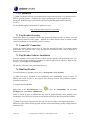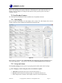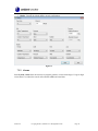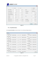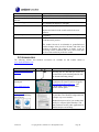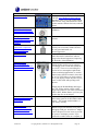
1
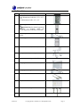
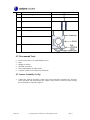
Ambient Weather WS-2080A Wireless Home Weather Station User Manual Table of Contents 1. 2. 3. 4. Introduction ..................................................................................................................................... 3 Warnings and Cautions ................................................................................................................... 3 Quick Start Guide............................................................................................................................ 3 Getting Started ................................................................................................................................ 3 4.1 Parts List................................................................................................................................. 4 4.2 Recommend Tools .................................................................................................................. 5 4.3 Sensor Assembly Set Up ........................................................................................................ 5 4.4 Display Console ................................................................................................................... 14 4.4.1 Display Console Layout ................................................................................................... 14 4.4.1 Initial Display Console Set Up ......................................................................................... 16 4.4.2 Radio Controlled Clock (RCC) ........................................................................................ 16 4.4.3 Sensor Operation Verification .......................................................................................... 16 5. Weather Station Installation .......................................................................................................... 17 5.1 Pre Installation Checkout ..................................................................................................... 17 5.2 Site Survey ........................................................................................................................... 17 5.3 Final Installation of Sensor Array......................................................................................... 17 6. Console Operation......................................................................................................................... 17 6.1 Time ..................................................................................................................................... 18 6.2 Date ...................................................................................................................................... 19 6.3 Wind ..................................................................................................................................... 20 6.4 Rain ...................................................................................................................................... 21 6.5 Barometric Pressure ............................................................................................................. 22 6.6 Pressure Graph ..................................................................................................................... 23 6.7 Weather Forecast (Tendency) ............................................................................................... 23 6.8 Indoor Temperature .............................................................................................................. 24 6.9 Indoor Humidity ................................................................................................................... 25 6.10 Outdoor Temperature, Wind Chill and Dew Point ............................................................... 26 6.11 Outdoor Humidity ................................................................................................................ 27 6.12 Memory ................................................................................................................................ 27 6.13 Calibration Mode.................................................................................................................. 27 6.13.1 Temperature Calibration............................................................................................... 28 6.13.2 Humidity Calibration ................................................................................................... 28 6.13.3 Wind Speed Calibration ............................................................................................... 28 6.13.4 Calibration Mode ......................................................................................................... 29 6.14 Lost Sensor Resynchronization ............................................................................................ 29 6.15 Restoring to Factory Default ................................................................................................ 29 7. PC Software .................................................................................................................................. 30 7.1 EasyWeather Overview ........................................................................................................ 30 7.2 Connect PC Connection ....................................................................................................... 30 7.3 EasyWeather Software Installation ....................................................................................... 30 7.4 Run EasyWeather ................................................................................................................. 30 7.5 EasyWeather Features .......................................................................................................... 31 7.5.1 Main Display .................................................................................................................... 31 Version 2.4 ©Copyright 2015, Ambient LLC. All Rights Reserved. Page 1 7.5.2 Set-up and Alarms ............................................................................................................ 31 7.5.3 Alarms .............................................................................................................................. 32 7.5.4 Max/Min Values ............................................................................................................... 33 7.5.5 Historical Data ................................................................................................................. 34 7.5.6 Graph Data ....................................................................................................................... 34 7.5.7 Clearing Rainfall from EasyWeather................................................................................ 35 7.5.8 Uploading to Websites including Wunderground.com ..................................................... 35 7.5.9 EasyWeather Legal Notes ................................................................................................ 36 8. Glossary of Terms ......................................................................................................................... 36 9. Specifications ................................................................................................................................ 37 9.1 Wireless Specifications ........................................................................................................ 37 9.2 Measurement Specifications................................................................................................. 37 9.3 Power Consumption ............................................................................................................. 37 9.4 Cable Lengths ....................................................................................................................... 37 10. Maintenance ............................................................................................................................. 37 11. Troubleshooting Guide ............................................................................................................. 37 12. Accessories ............................................................................................................................... 40 13. Liability Disclaimer .................................................................................................................. 42 14. FCC Statement.......................................................................................................................... 42 15. Warranty Information ............................................................................................................... 43 Version 2.4 ©Copyright 2015, Ambient LLC. All Rights Reserved. Page 2 1. Introduction Thank you for your purchase of the Ambient Weather WS-2080 wireless weather station. The following user guide provides step by step instructions for installation, operation and troubleshooting. To download the latest manual and additional troubleshooting tips, please visit: http://ambientweather.wikispaces.com/ws2080 2. Warnings and Cautions Warning: Any metal object may attract a lightning strike, including your weather station mounting pole. Never install the weather station in a storm. Warning: Installing your weather station in a high location may result in injury or death. Perform as much of the initial check out and operation on the ground and inside a building or home. Only install the weather station on a clear, dry day. 3. Quick Start Guide Although the manual is comprehensive, much of the information contained may be intuitive. In addition, the manual may not flow properly because the sections are organized by components. The following Quick Start Guide provides only the necessary steps to install, operate the weather station, and upload to weather servers, along with references to the pertinent sections. Step 1 3 6 4 5 7 8 Required Description Assemble and power up the sensor array Power up the display console and synchronize with sensor array and thermo-hygrometer-barometer Mount the sensor array Set date and time on console Calibrate the relative pressure to sea-level conditions (local airport) on console Reset the rain to zero on console Optional Connect to PC Section 4.1-4.3 4.4 5 6.1-6.2 6.5 6.4 7 4. Getting Started The WS-2080 weather station consists of a display console (receiver), a thermo-hygrometer transmitter unit, a wind direction sensor, a wind speed sensor, a rain gauge, mounting hardware, USB cable and a PC software package on CD-ROM. Version 2.4 ©Copyright 2015, Ambient LLC. All Rights Reserved. Page 3 4.1 Parts List QTY 1 Item Display Console Frame Dimensions (LxWxH): 6.75” x 4.5” x 1.25” LCD Dimensions (LxW): 4.5” x 3.5” 1 Thermo-hygrometer transmitter Image Important Note: the thermo-hygrometer transmitter is shipped inside the Thermo-hygrometer transmitter rain shield. 1 Thermo-hygrometer transmitter bracket 1 Thermo-hygrometer transmitter rain shield 1 Wind direction sensor (wind vane) 1 Wind speed sensor (wind cups) 1 Anemometer mounting arm (L: 12”) 1 Rain gauge 1 Rain gauge mounting bracket 1 USB cable (L: 41”) 1 Easy Weather CD 3 1” nuts and bolts (long) 1 13/16” bolt (short) Version 2.4 mounting ©Copyright 2015, Ambient LLC. All Rights Reserved. Page 4 QTY 1 ½” set screw (long) Item 1 3/8”set screw (short) (Optional) 1 Upper pole (L: 12”) 1 Lower pole (L: 12”) 2 Pole mounting U-bolt 4 Pole mounting clamps 4 Pole mounting U-bolt nuts Image 4.2 Recommend Tools Precision screwdriver (for small Phillips screws) Pliers Phillips screwdriver Flat blade screwdriver Tack (small) hammer or rubber mallet Compass or GPS (for wind direction calibration) 4.3 Sensor Assembly Set Up 1. Connect the wind cup assembly to either end of the anemometer mounting arm. Align the holes, and fasten with long bolt and nut. Tighten with precision screwdriver while securing the nut with pliers, as shown in Figure 1. Version 2.4 ©Copyright 2015, Ambient LLC. All Rights Reserved. Page 5 Figure 1 2. Connect the wind vane assembly to the other end of the anemometer mounting arm. Align the holes, and fasten with long bolt and nut. Tighten with precision screwdriver while securing the nut with pliers, as shown in Figure 2. Figure 2 Version 2.4 ©Copyright 2015, Ambient LLC. All Rights Reserved. Page 6 3. Connect the anemometer assembly to the top mounting pole, align the holes, and fasten with short set screw (optional, we recommend NOT connecting this) and long bolt and nut. Tighten with precision screwdriver while securing the nut with pliers, as shown in Figure 3. Note: This may be a tight fit – rotate the pole back and forth to shave off some of the plastic, and use a small hammer to tap the top of the anemometer mounting arm while securing the pole on a solid, flat surface. Use a piece of cloth or padding to dampen the hammer and avoid damage to the anemometer mounting arm. Figure 3 Version 2.4 ©Copyright 2015, Ambient LLC. All Rights Reserved. Page 7 4. Connect the rain gauge with long set screw. Tighten with precision screwdriver, as shown in Figure 4. Note: There may be a slight “play” in the rain gauge and the screw may not be flush. Do not force the screw. Attach the rain gauge mounting arm to the upper mounting pole, at right angles to the wind speed and wind direction assembly to avoid obstruction of rainfall. Note: There are two mounting holes on the side of the rain gauge in the event you wish to mount the rain gauge in a different location than the mounting arm. Figure 4 Version 2.4 ©Copyright 2015, Ambient LLC. All Rights Reserved. Page 8 5. Connect the thermo-hygrometer with short bolt and nut. Tighten with precision screwdriver, as shown in Figure 5. Slide the rain shield over the thermo-hygrometer after connecting the cables from the anemometer and rain gauge (step 7). Attach to the thermo-hygrometer mounting arm to the upper mounting pole. Figure 5 Version 2.4 ©Copyright 2015, Ambient LLC. All Rights Reserved. Page 9 6. Fasten the lower mounting pole (which is swaged on the top end) to your mounting pole or bracket (purchased separately) with the two U-Bolts, clamps and nuts as shown in Figure 6. Tighten the lower mounting pole to your mounting pole with the mounting clamp assembly with a wrench, as shown in Figure 6. Slide the top weather station pole (with the sensor array) into the lower pole (connected to your mounting pole) when your station is finally mounted. Attach the upper mounting poke to your mounting pole with the second mounting clamp assembly with a wrench, as shown in Figure 6. When you install the weather station, you will need to calibrate the anemometer pointer to true north. True north can be estimated with a compass (which points to magnetic north) or a GPS, which provides true north. Wind direction is defined as the direction the wind is coming from (example, Winds from the north). Note the four channels on the side of the wind vane. Each quadrant is labeled North, South, East and West (reference Figure 6 as an example for “E” or East). Locate the North direction (“N”) and mark it with a piece of tape for future reference. You will need this for wind direction calibration upon final assembly. Version 2.4 ©Copyright 2015, Ambient LLC. All Rights Reserved. Page 10 Figure 6 Version 2.4 ©Copyright 2015, Ambient LLC. All Rights Reserved. Page 11 Connect the wind speed cable to the wind direction phone jack, as shown in Figure 7. Connect the wind direction cable to the thermo-hygrometer phone jack (reference the label on the thermo-hygrometer). Connect the rain gauge cable to the thermo-hygrometer phone jack (reference the label on the thermo-hygrometer). Figure 7 Insert two AA batteries in the thermo-hygrometer, as shown in Figure 8. The transmitter LED will light up momentarily (4 seconds), and then flash once every 48 seconds for each transmission update. Note: Do not install the batteries backwards. You can permanently damage the thermo-hygrometer. Do not use rechargeable batteries. Note: We recommend installing Lithium AA batteries: http://www.ambientweather.com/enaaliba4pa.html Lithium batteries provide longer life and operate in colder temperatures. Version 2.4 ©Copyright 2015, Ambient LLC. All Rights Reserved. Page 12 Figure 8 Version 2.4 ©Copyright 2015, Ambient LLC. All Rights Reserved. Page 13 Install the rain shield over the thermo-hygrometer/transmitter, as shown in Figure 9, and use the enclosed zip ties to clean up the cables. Figure 9 4.4 Display Console 4.4.1 Display Console Layout The display console layout is shown in Figure 10. Version 2.4 ©Copyright 2015, Ambient LLC. All Rights Reserved. Page 14 7. 1. 8. 9. 2. 10. 3. 11. 4. 5. 12. 13. 6. 14. Figure 10 1. 2. 3. 4. 5. 6. 7. 8. 9. 10. 11. 12. 13. 14. Time Wind direction Barometric Pressure Barometric trend Indoor Temperature Outdoor Temperature Memory Radio Controlled Clock (RCC) Date Rainfall Weather Forecast Indoor Humidity Outdoor reception signal Outdoor Humidity Version 2.4 ©Copyright 2015, Ambient LLC. All Rights Reserved. Page 15 4.4.1 Initial Display Console Set Up Note: The sensor array must be powered and updating before powering up the console, or the console will timeout searching for the sensors. Perform this step last. Make certain the weather station sensor array is at least 10’ away from the console and within 300’ of the console. If the weather station is too close or two far away, it will not receive a proper signal. Insert two AA batteries into the battery compartment on the back of the display. After inserting the batteries into the console, all of the LCD segments will light up for a few seconds to verify all segments are operating properly. The unit will instantly display indoor temperature, humidity, barometer, tendency, date and time. The wind speed, wind direction, rain, and outdoor temperature and humidity will update on the display within a few minutes. Do not Press any menu keys until the outside transmitter report in, otherwise the outdoor sensor search mode will be terminated. When the outdoor transmitter data has been received, the console will automatically switch to the normal mode from which all further settings can be performed. If it does not update, please reference the troubleshooting guide in Section 10. 4.4.2 Radio Controlled Clock (RCC) After the remote sensor is powered up, the sensor will transmit weather data for 30 seconds, and then the sensor will begin radio controlled clock (RCC) reception. During the RCC time reception period (maximum 10 minutes), no weather data will be transmitted to avoid interference. If the signal reception is not successful within 1 minute, the signal search will be cancelled and will automatically resume every two hours until the signal is successfully captured. The regular RF link will resume once RCC reception routine is finished. In some locations, RCC reception may take a couple of days to receive the signal. Note: The RCC is a shortwave signal originating near Fort Collins, CO and travels thousands of miles by bouncing between the ionosphere and the ground. Solar interference attenuates this signal. Thus, it is most likely to be received at night. 4.4.3 Sensor Operation Verification The following steps verify proper operation of the sensors prior to installing the sensor array. 1. Verify proper operation of the rain gauge. Tip the sensor array back and forth several times. You should hear a “clicking” sound within the rain gauge. Verify the rain reading on the display console is not reading 0.00. Each “click” represents 0.01 inches of rainfall. 2. Verify proper operation of the wind direction. Align the wind vane pointer to North (as determined in Section 4.3). Verify the display reads North. Repeat for each quadrant (North, South, East, and West). 3. Verify proper operating of the wind speed. Rotate the wind cups manually or with a fan. Verify the wind speed is not reading 0.0. 4. Verify proper operation of the indoor and outdoor temperature. Verify the indoor and outdoor temperature match closely with the console and sensor array in the same location (about 10’ apart). The sensors should be within 4°F (2°C) (the accuracy is ± 2°F / 1°C). Allow about 30 minutes for both sensors to stabilize. 5. Verify proper operation of the indoor and outdoor humidity. Verify the indoor and Version 2.4 ©Copyright 2015, Ambient LLC. All Rights Reserved. Page 16 outdoor humidity match closely with the console and sensor array in the same location (about 10’ apart). The sensors should be within 8% (the accuracy is ± 4%). Allow about 30 minutes for both sensors to stabilize. 5. Weather Station Installation 5.1 Pre Installation Checkout Before installing your weather station in the permanent location, we recommend operating the weather station for one week in a temporary location with easy access. This will allow you to check out all of the functions, insure proper operation, and familiarize you with the weather station and calibration procedures. This will also allow you to test the wireless range of the weather station. 5.2 Site Survey Perform a site survey before installing the weather station. Consider the following: 1. You must clean the rain gauge once per year and change the batteries every two years. Provide easy access to the weather station. 2. Avoid radiant heat transfer from buildings and structures. In general, install the sensor array at least 5’ from any building, structure, ground, or roof top. 3. Avoid wind and rain obstructions. The rule of thumb is to install the sensor array at least four times the distance of the height of the tallest obstruction. For example, if the building is 20’ tall, install 4 x 20’ = 80’ away. Use common sense. If the weather station is installed next to a tall building, the wind and rain will not be accurate. 4. Wireless Range. The radio communication between receiver and transmitter in an open field can reach a distance of up to 330 feet, providing there are no interfering obstacles such as buildings, trees, vehicles, high voltage lines. Wireless signals will not penetrate metal buildings. 5. Radio interference such as PCs, radios or TV sets can, in the worst case, entirely cut off radio communication. Please take this into consideration when choosing console or mounting locations. 6. Visit Ambient Weather Mounting Solutions for assistance and ideas for mounting your weather station: http://www.ambientweather.com/amwemoso.html 5.3 Final Installation of Sensor Array Mount the weather station in the permanent location. To calibrate the wind direction, align the wind direction pointer with the “N” marking on the side of the wind direction sensor, as described in Section 4.3. Rotate the upper pole until the vane pointer, marking, and true north wind direction are aligned. 6. Console Operation Note: You can also program the weather station console through the PC software (recommended). Note: The display console has six keys for basic operation: menu key, up key, down key, enter key, history key, and on/off key. To enter the Set mode, press the menu key. The Set mode can be exited at any time by either Version 2.4 ©Copyright 2015, Ambient LLC. All Rights Reserved. Page 17 pressing the history key or waiting for the 30-second time-out to take effect. setting by pressing the menu key again. You can skip over any Holding the up or down key when in the Set mode will increase/decrease values rapidly. 6.1 Time Press the menu key to enter the TIME Set Mode. You can skip over any setting by selecting the enter key. Figure 11 1. Display (LCD) Contrast Level. The display contrast value will begin flashing (example, lcd0 thru lcd8). The lowest LCD contrast level 0 and the highest LCD contrast level is 8. Press the up key or down key to adjust the contrast level from 0 to 8 (the default is 5). 2. Time Zone. Press the enter key to display the time zone. The time zone value will begin flashing. Press the up key or down key to adjust the time zone from -12 to 12, based on the number of hours from Coordinated Universal Time, or Greenwich Mean Time (GMT). The following table provides times zones throughout the world. Locations in the eastern hemisphere are positive, and locations in the western hemisphere are negative. Hours from GMT -12 -11 -10 -9 -8 -7 -6 -5 -4 -3 -2 -1 0 1 2 3 4 5 6 7 Version 2.4 Time Zone IDLW: International Date Line West NT: Nome AHST: Alaska-Hawaii Standard CAT: Central Alaska HST: Hawaii Standard YST: Yukon Standard PST: Pacific Standard MST: Mountain Standard CST: Central Standard EST: Eastern Standard AST: Atlantic Standard --AT: Azores WAT: West Africa GMT: Greenwich Mean WET: Western European CET: Central European EET: Eastern European BT: Baghdad --------- Cities --Nome, AK Honolulu, HI Yukon Territory Los Angeles, CA, USA Denver, CO, USA Chicago, IL, USA New York, NY, USA Caracas São Paulo, Brazil Azores, Cape Verde Islands --London, England Paris, France Athens, Greece Moscow, Russia Abu Dhabi, UAE Tashkent Astana Bangkok ©Copyright 2015, Ambient LLC. All Rights Reserved. Page 18 Hours from GMT 8 9 10 11 12 Time Zone CCT: China Coast JST: Japan Standard GST: Guam Standard --IDLE: International Date Line East NZST: New Zealand Standard Cities Bejing Tokyo Sydney Magadan Wellington, New Zealand 3. 12/24 Hour Format. Press the enter key to change the 12/24 hour format. Press the up key or down key to alternate the display unit between 12 hour format and 24 hour format. 4. Daylight Saving Time. Press the enter key to turn ON and OFF daylight savings time (DST) observance (example, Arizona and parts of Indiana do not observe daylight savings time). Press the on/off key to alternate the display unit between ON and OFF. 5. Change Hour. Press the enter key to set the hour. Press the up key or down key to change the hour setting. The RCC time will override the manual set time. 6. Change Minute. Press the enter key to set the minute. Press the up key or down key to change the minute setting. Manually setting the time overrides the automatic RCC time. 6.2 Date Note: This is a continuation of the previous section. To enter this mode, you must begin at Section 6.1 and proceed to this section. Press the menu key to enter the Date Set Mode. You can skip over any setting by selecting the enter key. Figure 12 1. Alarm Time, Date and Date of the Week. The date will be flashing. Press the up key or down key to alternate the display between the alarm time, and date and week date. 2. Date Format Press the enter key to display the date format (Md for month/day or Dm for Day/Month). The date value will begin flashing. Press the up key or down key to adjust the alternate the display between the DD-MM format and MM-DD format for the date. 3. Change Year. Press the enter key to set the year. The year will begin flashing. Press the up key or down key to change the year setting. 4. Change Month. Press the enter key to set the month. The month will begin flashing. Press the up key or down key to change the month setting. 5. Change Day. Press the enter key to set the day. The day will begin flashing. Press the up Version 2.4 ©Copyright 2015, Ambient LLC. All Rights Reserved. Page 19 key or down key to change the day setting. 6. Change Alarm Hour. Press the enter key to set the alarm hour. The alarm hour and ALARM will begin flashing. Press the up key or down key to change the alarm hour setting. 7. Change Alarm Minute. Press the enter key to set the alarm minute. The alarm minute will begin flashing. Press the up key or down key to change the alarm minute setting. Press the ON/OFF key to select the alarm on or off (if the alarm is enabled, the alarm icon will be turned on in the Time section). 6.3 Wind Note: This is a continuation of the previous section. To enter this mode, you must begin at Section 6.1 and proceed to this section. Press the menu key to enter the Wind Set Mode. You can skip over any setting by selecting the enter key. Figure 13 1. Average Wind Speed and Wind Gust. Press the up key or down key to alternate the display between the 48 second Wind Speed Average and Gust Speed (or the maximum wind speed in the update period). 2. Wind Speed Units. Press the enter key to set the wind speed units. The wind speed units will begin flashing. Press the up key or down key to alternate the display unit between km/h, mph, m/s, knots, and bft (or Beaufort scale). 3. Wind Speed High Alarm. Press the enter key to set the wind speed high alarm setting. The wind speed high alarm and HI AL (high alarm) will begin flashing. Press the up key or down key to adjust the high wind speed alarm. Press the ON/OFF key to select the alarm on or off (if the alarm is enabled, the alarm icon will be turned on). 4. Wind Direction Alarm. Press the enter key to set the wind direction alarm setting. The wind direction alarm and Direct (wind direction) will begin flashing. Version 2.4 ©Copyright 2015, Ambient LLC. All Rights Reserved. Page 20 Press the up key or down key to adjust the wind direction alarm. Press the ON/OFF key to select the alarm on or off (if the alarm is enabled, the alarm icon will be turned on). 5. Wind Speed Record High. Press the enter key to display maximum wind speed record since the last reset. The maximum record will be flashing, and the MAX icon will light up (in the tendency section). To reset, press the enter key for 3 seconds, and the maximum value (and associated date and time) (and associated date and time) will be reset to current reading. 6.4 Rain Note: This is a continuation of the previous section. To enter this mode, you must begin at Section 6.1 and proceed to this section. Press the menu key to enter the Rain Set Mode. You can skip over any setting by selecting the enter key. Figure 14 1. Rain Increment. Press the up key or down key to alternate the display between 1 hour, 24 hour, week, month and total rain increments. 2. Rain Units. Press the enter key to set the rain units. The rain units will begin flashing. Press the up key or down key to alternate the display unit between inches and mm. Rain High Alarm. Press the enter key to set the rain high alarm function. The rain high alarm and HI AL (high alarm) will begin flashing. Press the up key or down key to adjust the rain alarm. Press the ON/OFF key to select the alarm on or off (if the alarm is enabled, the alarm icon will be turned on). 3. Rain Record High. Press the enter key to display maximum rain record since the last reset. The maximum record will be flashing, and the MAX icon will light up (in the tendency section). To reset, press the enter key for 3 seconds, and the maximum value (and associated date and time) will be reset to current reading. 4. Reset Rain. Press the enter key to reset the rain values. The rain and CLEAR will begin flashing. To reset, press enter key for 3 seconds and the 1 hour, 24 hour, week, month and total rain will reset to 0. Version 2.4 ©Copyright 2015, Ambient LLC. All Rights Reserved. Page 21 6.5 Barometric Pressure Note: The weather station console displays two different pressures: absolute (measured) and relative (corrected to sea-level). To compare pressure conditions from one location to another, meteorologists correct pressure to sea-level conditions. Because the air pressure decreases as you rise in altitude, the sea-level corrected pressure (the pressure your location would be at if located at sea-level) is generally higher than your measured pressure. Thus, your absolute pressure may read 28.62 inHg (969 mb) at an altitude of 1000 feet (305 m), but the relative pressure is 30.00 inHg (1016 mb). The standard sea-level pressure is 29.92 in Hg (1013 mb). This is the average sea-level pressure around the world. Relative pressure measurements greater than 29.92 inHg (1013 mb) are considered high pressure and relative pressure measurements less than 29.92 inHg are considered low pressure. To determine the relative pressure for your location, locate an official reporting station near you (the internet is best source for real time barometer conditions, such as Weather.com or Wunderground.com), and set your weather station to match the official reporting station. Note: This is a continuation of the previous section. To enter this mode, you must begin at Section 6.1 and proceed to this section. Press the menu key to enter the Pressure Mode. You can skip over any setting by selecting the enter key. Figure 15 1. Relative vs. Absolute Pressure Display. Press the up key or down key to alternate the display between relative (rel) pressure and absolute (abs) pressure. 2. Pressure Units. Press the enter key to set the pressure units. The pressure units will begin flashing. Press the up key or down key to alternate the display unit between hPa, inHg and mmHg. 3. Relative Pressure Calibration. When Absolute (abs) pressure is selected, this step will be skipped. Press the enter key to set the relative pressure calibration. The relative pressure will flash. Version 2.4 ©Copyright 2015, Ambient LLC. All Rights Reserved. Page 22 Press the up key or down key to change the value. 4. Pressure High Alarm. Press the enter key to set the pressure high alarm function. Pressure and HI AL (high alarm) icon will flash. Press the up key or down key to change the value. Press the ON/OFF key to select the alarm on or off (if the alarm is enabled, the alarm icon will be turned on). 5. Pressure Low Alarm. Press the enter key to set the pressure low alarm function. Pressure and LO AL (high alarm) icon will flash. Press the up key or down key to change the value. Press the ON/OFF key to select the alarm on or off (if the alarm is enabled, the alarm icon will be turned on). 6. Pressure Record High. Press the enter key to display maximum pressure record since the last reset. The maximum record will be flashing, and the MAX icon will light up (in the tendency section). To reset, press the enter key for 3 seconds, and the maximum value (and associated date and time) (and associated date and time) will be reset to current reading. 7. Pressure Record Low. Press the enter key to display minimum pressure record since the last reset. The minimum record will be flashing, and the MIN icon will light up (in the tendency section). To reset, press the enter key for 3 seconds, and the minimum value (and associated date and time) will be reset to current reading. 6.6 Pressure Graph Note: The weather station bar graph flashes from left to right to prevent screen burn in. This feature cannot be turned off. Note: This is a continuation of the previous section. To enter this mode, you must begin at Section 6.1 and proceed to this section. Press the enter key to set the pressure graph history time axis. The pressure graph time axis will begin flashing. Press the up key or down key to change the pressure history time axis between 12 hours and 24 hours. 6.7 Weather Forecast (Tendency) Note: The weather forecast or pressure tendency is based in the rate of change of barometric pressure. In general, when the pressure increases, the weather improves (sunny to partly cloudy) and when the pressure decreases, the weather degrades (cloudy to rain). The weather forecast is an estimation or generalization of weather changes in the next 24 to 48 hours, and varies from location to location. The tendency is simply a tool for projecting weather conditions and is never to be relied upon as an accurate method to predict the weather. Version 2.4 ©Copyright 2015, Ambient LLC. All Rights Reserved. Page 23 Note: This is a continuation of the previous section. To enter this mode, you must begin at Section 6.1 and proceed to this section. Press the menu key to enter the TENDANCY Set Mode. You can skip over any setting by selecting the enter key. Figure 16 1. Change Tendency. Press the up key or down key to alternate the display between SUNNY, PARTLY CLOUDY and CLOUDY, and RAINY. 2. Pressure Threshold. Press the enter key to change the pressure threshold. The up and down arrow and pressure tendency will be flashing. Press the up key or down key to adjust the pressure threshold from 2.0 to 4.0 hPa/hr (the default is 2 hPa/hr). 3. Storm Threshold. Press the enter key to change the storm threshold. The up and down arrow and pressure tendency will be flashing. Press the up key or down key to adjust the pressure threshold from 3.0 to 9.0 hPa/hr (the default is 4 hPa/hr). 6.8 Indoor Temperature Note: This is a continuation of the previous section. To enter this mode, you must begin at Section 6.1 and proceed to this section. Press the menu key to enter the INDOOR TEMPERATURE Set Mode. You can skip over any setting by selecting the enter key. Figure 17 1. Indoor Temperature Units. Press the up key or down key to alternate the display unit between °C and °F. Version 2.4 ©Copyright 2015, Ambient LLC. All Rights Reserved. Page 24 2. Indoor Temperature High Alarm. Press the enter key to set the indoor temperature high alarm function. The indoor temperature and HI AL (high alarm) will begin flashing. Press the up key or down key to change the value. Press the ON/OFF key to select the alarm on or off (if the alarm is enabled, the alarm icon will be turned on). 3. Indoor Temperature Low Alarm. Press the enter key to set the indoor temperature low alarm function. The indoor temperature and LO AL (high alarm) will begin flashing. 4. Press the up key or down key to change the value. Press the ON/OFF key to select the alarm on or off (if the alarm is enabled, the alarm icon will be turned on). 5. Indoor Temperature Record High. Press the enter key to display maximum indoor temperature record since the last reset. The maximum temperature record and MAX icon (in the tendency section) will begin flashing. To reset, press the enter key for 3 seconds, and the maximum value (and associated date and time) (and associated date and time) will be reset to current reading. 6. Indoor Temperature Record Low. Press the enter key to display minimum indoor temperature record since the last reset. The minimum temperature record and MIN icon (in the tendency section) will begin flashing. To reset, press the enter key for 3 seconds, and the minimum value (and associated date and time) will be reset to current reading. 6.9 Indoor Humidity Note: This is a continuation of the previous section. To enter this mode, you must begin at Section 6.1 and proceed to this section. Press the menu key to enter the INDOOR HUMIDITY Set Mode. You can skip over any setting by selecting the enter key. Figure 18 1. Indoor Humidity High Alarm. Press the enter key to set the indoor humidity high alarm function. The indoor humidity and HI AL (high alarm) will begin flashing. Press the up key or down key to change the value. Version 2.4 ©Copyright 2015, Ambient LLC. All Rights Reserved. Page 25 Press the ON/OFF key to select the alarm on or off (if the alarm is enabled, the alarm icon will be turned on). 2. Indoor Humidity Low Alarm. Press the enter key to set the indoor humidity low alarm function. The indoor humidity and LO AL (high alarm) will begin flashing. 3. Press the up key or down key to change the value. Press the ON/OFF key to select the alarm on or off (if the alarm is enabled, the alarm icon will be turned on). 4. Indoor Humidity Record High. Press the enter key to display maximum indoor humidity record since the last reset. The maximum humidity record and MAX icon (in the tendency section) will begin flashing. To reset, press the enter key for 3 seconds, and the maximum value (and associated date and time) (and associated date and time) will be reset to current reading. 5. Indoor Humidity Record Low. Press the enter key to display minimum indoor humidity record since the last reset. The minimum humidity record and MIN icon (in the tendency section) will begin flashing. To reset, press the enter key for 3 seconds, and the minimum value (and associated date and time) will be reset to current reading. 6.10 Outdoor Temperature, Wind Chill and Dew Point Note: This is a continuation of the previous section. To enter this mode, you must begin at Section 6.1 and proceed to this section. Figure 19 1. Outdoor Temperature, Wind chill and Dew Point. Press the up key or down key to alternate the display between the outdoor temperature, wind chill and dew point. 2. Outdoor Temperature Units. Press the up key or down key to alternate the display unit between °C and °F. 3. Outdoor Temperature High Alarm. Press the enter key to set the outdoor temperature high alarm function. The outdoor temperature and HI AL (high alarm) will begin flashing. Press the up key or down key to change the value. Press the ON/OFF key to select the alarm on or off (if the alarm is enabled, the alarm icon will be turned on). Version 2.4 ©Copyright 2015, Ambient LLC. All Rights Reserved. Page 26 4. Outdoor Temperature Low Alarm. Press the enter key to set the outdoor temperature low alarm function. The outdoor temperature and LO AL (high alarm) will begin flashing. 5. Press the up key or down key to change the value. Press the ON/OFF key to select the alarm on or off (if the alarm is enabled, the alarm icon will be turned on). 6. Outdoor Temperature Record High. Press the enter key to display maximum outdoor temperature record since the last reset. The maximum temperature record and MAX icon (in the tendency section) will begin flashing. To reset, press the enter key for 3 seconds, and the maximum value (and associated date and time) will be reset to current reading. 7. Outdoor Temperature Record Low. Press the enter key to display minimum outdoor temperature record since the last reset. The minimum temperature record and MIN icon (in the tendency section) will begin flashing. To reset, press the enter key for 3 seconds, and the minimum value (and associated date and time) will be reset to current reading. 8. Repeat the above steps for wind chill and dew point. 6.11 Outdoor Humidity Please reference Section Indoor Humidity. The outdoor procedure is similar to the indoor humidity procedure. Note: This is a continuation of the previous section. To enter this mode, you must begin at Section 6.1 and proceed to this section. 6.12 Memory The console stores up to 4080 complete sets of weather data with associated time and date stamp. The base station will lose all of the weather data if there a power interruption. In the event the memory is full, the old data is overwritten by the new data. Press the history key to review the historical data. 1. Select the down key to review historical data archived in the console. Select the up key to advance historical data archived in the console (default is 30 minute intervals). When history 2. data displayed, the corresponding date and time will be displayed at the time section area. The historical archive interval can only be changed using the PC software that comes with this product. The factory default archive interval is 30 minutes. 3. Clear Memory. Press the history again key to clear memory. Press the enter key. The memory fill icon will be flashing. Press and hold enter key for 3 seconds to clear memory. 6.13 Calibration Mode In addition to the sea-level barometer calibration in the previous section, the following parameters can Version 2.4 ©Copyright 2015, Ambient LLC. All Rights Reserved. Page 27 also be calibrated: Indoor Temperature Outdoor Temperature Indoor Humidity Outdoor Humidity Wind Speed 6.13.1 Temperature Calibration Temperature errors can occur when a sensor is placed too close to a heat source (such as a building structure, the ground and when placed in direct sunlight without proper shielding in hot weather environments). The temperature sensor utilizes a resistive thermal device (RTD), which varies the resistance as a function of temperature. Due to manufacturing tolerances in resistance, the accuracy of the sensor is ± 2 °F. To improve on this accuracy, the indoor and outdoor temperature readings can be adjusted or calibrated from the display console. To calibrate temperature, we recommend a mercury or red spirit (fluid) thermometer. Bi-metal (dial) and other digital thermometers are not a good source and have their own margin of error. Using a local weather station in your area is also a poor source due to changes in location, timing (airport weather stations are only updated once per hour) and possible calibration errors (many official weather stations are not properly installed and calibrated). Place the sensor in a shaded, controlled environment next to the fluid thermometer, and allow the sensor to stabilize for 48 hours. Compare this temperature to the fluid thermometer and adjust the console to match the fluid thermometer. 6.13.2 Humidity Calibration Humidity is a difficult parameter to measure accurately and drifts over time. Humidity errors can occur when placed too close to the ground, near grass or other sources of humidity. The hygrometer sensor utilizes a capacitor, which varies as a function of humidity. Due to manufacturing tolerances, the accuracy of the sensor is ± 5%. To improve on this accuracy, the indoor and outdoor humidity readings can be adjusted or calibrated from the display console. To calibrate humidity, you will need an accurate source, such as a sling psychrometer or Humidipaks One Step Calibration kit, available from Ambient Weather. 6.13.3 Wind Speed Calibration Wind speed is the most sensitive to installation constraints. The rule of thumb for properly installing a wind speed sensor is 4 x the distance of the tallest obstruction. For example, if your house is 20’ tall and you mount the sensor on a 5’ pole: Distance = 4 x (20 – 5)’ = 60’. Many installations are not perfect and installing the weather station on a roof can be difficult. Thus, you can calibrate for this error with a wind speed multiplier. In addition to the installation challenges, wind cup bearings (moving parts) wear over time. Without a calibrated source, wind speed can be difficult to measure. We recommend using a calibrated Version 2.4 ©Copyright 2015, Ambient LLC. All Rights Reserved. Page 28 wind meter (available from Ambient Weather) and a constant speed, high speed fan. 6.13.4 Calibration Mode While in the Normal Mode, press the ON/OFF key for 8 seconds to enter the calibration mode, and the ADJ icon will be displayed. You can skip over any setting by selecting the enter key. To exit the calibration mode at any time, select the history key 1. Wind Speed Calibration (default is 1.0, adjustment range 0.75 to 1.25). Press the up or down key to increase or decrease the wind speed multiplier to match the calibrated source. Press the ON/OFF key, and the value will return to the uncalibrated value. 2. Indoor Temperature Calibration. Press the enter key to calibrate the temperature in 0.1°C (0.18 °F) increments. Press the up or down key to increase or decrease the temperature bias to match the calibrated source. Press the ON/OFF key, and the value will return to the uncalibrated value. 3. Indoor Humidity Calibration. Press the enter key to calibrate the humidity in 1% increments. Press the up or down key to increase or decrease the humidity bias to match the calibrated source. Press the ON/OFF key, and the value will return to the uncalibrated value. 4. Outdoor Temperature Calibration. Press the enter key to calibrate the temperature in 0.1° increments. Press the up or down key to increase or decrease the temperature bias to match the calibrated source. Press the ON/OFF key, and the value will return to the uncalibrated value. 5. Outdoor Humidity Calibration. Press the enter key to calibrate the humidity in 1% increments. Press the up or down key to increase or decrease the humidity bias to match the calibrated source. Press the ON/OFF key, and the value will return to the uncalibrated value. Press the enter key to exit the calibration mode. Note: The dew point and wind chill are based on the calibration values. 6.14 Lost Sensor Resynchronization If the signal is lost between the remote sensor (or transmitter) and the display console (or the receiver), to resynchronize, while in normal mode, press and hold the down key for 5 seconds. The transmitter search icon will appear. Please wait several minutes for the search icon to turn off and the remote sensor reports in. Do not touch any buttons until synchronization is complete. 6.15 Restoring to Factory Default To restore the console to factory default, press and hold the up key for 30 seconds. The console will beep and reset. Wait several minutes for the remote sensor to synchronize. Version 2.4 ©Copyright 2015, Ambient LLC. All Rights Reserved. Page 29 7. PC Software Note: EasyWeather software is included with this weather station package. Easy Weather runs on most PC operating systems. Cumulus is free internet publishing PC software application by Sandaysoft. WeatherSnoop is a paid software and internet publishing application for Macs by Tee-Boy. For EasyWeather updates and alternate PC applications, visit: http://ambientweather.wikispaces.com/ws2080 7.1 EasyWeather Overview EasyWeather allows you to display real-time data, program the display console, set alarms, view and export historical data and create graphs. Whereas the weather station console is limited to 4080 records, EasyWeather is only limited by your PC’s memory. 7.2 Connect PC Connection Connect the weather station console to the PC using the included USB cable. The computer should acknowledge the connection with a beep and the device installation notice will be displayed if connected for the first time. 7.3 EasyWeather Software Installation Insert the included CD into your hard drive and the software installer will automatically start. If it does not, browse to My Computer (or Computer) in windows and locate the CD Drive. Right click on this drive, select Explore and run Setup.exe. The software will install to the program files directory. 7.4 Run EasyWeather To run EasyWeather, in Windows, select Start -> All Programs -> Easy Weather. Note: You may be prompted to run EasyWeather as the administrator (Vista or newer). To perform this action, browse to the program files directory location using Windows explorer, commonly located here: C:\Program Files\EasyWeather Right Click on the EasyWeather.exe icon Privilege Level, select Run as Administrator. , select the Compatibility Tab and under Failure to run the program as administrator may limit the graphical display mode capability, since EasyWeather writes data to file locations deemed protected with strict Microsoft protection enabled. Note: If you run the program for the first time, the current weather will be displayed and at the bottom line of the window, and the program will show related information regarding reading historical data into the PC. Version 2.4 ©Copyright 2015, Ambient LLC. All Rights Reserved. Page 30 When there is large amount of archived data to be uploaded, it may take a few minutes before the system will respond to your requests. Otherwise, it will display the “read weather data fail” error message, since the USB port is reading the data from the memory and the system is not able to respond to requests. 7.5 EasyWeather Features The following section outlines the features available in the EasyWeather Software. 7.5.1 Main Display When you launch EasyWeather, the main display will be shown. The main display shows current weather conditions, alarm conditions and minimum and maximum data. Figure 20 When console is connected to PC, USB Connected will be displayed in the bottom right hand corner of the main display panel. If the console is not connected, USB Unconnected will be displayed. 7.5.2 Set-up and Alarms Select System | Setting from the menu bar to program general weather station console settings. Note: Changing a console setting may take several minutes to update. 1. Time Zone. Programs the time zone as referenced in Section 6.1. 2. Interval. Archive interval for memory storage, as referenced in Section 6.12. 3. Unit. Changes units of measure on the display console for measured parameters. Version 2.4 ©Copyright 2015, Ambient LLC. All Rights Reserved. Page 31 4. Pressure. Changes the sea-level pressure calibration, as referenced in Section 6.5. 5. Display. Formats the default display console configuration. Figure 21 7.5.3 Alarms Select System | Alarm from the menu bar to program general to set the alarm ranges. If a given high or low alarm is exceeded, the console will sound an audible and visual alert. Version 2.4 ©Copyright 2015, Ambient LLC. All Rights Reserved. Page 32 Figure 22 7.5.4 Max/Min Values Select System | Max/Min from the menu bar to view the historical highs and lows. Figure 23 Version 2.4 ©Copyright 2015, Ambient LLC. All Rights Reserved. Page 33 7.5.5 Historical Data Select Record | History from the menu bar to view the historical data,. This window displays the recorded history data in a spread sheet format. If you want to see all history data in a specified time period, enter the time duration and press Search to reload the historical data. You can export the selected historical data into a text format file by selecting the Export button. When memory on the console is full, select the Clear Memory button to clear memory on the console (remember to upload all of the data before pressing this button). If you want to start a new weather history record, select the Clear Data button to clear the database, and all historical weather data will be deleted (if you would like to keep a back up history file before deleting all weather data, you can make a copy of the “EasyWeather.dat” file into another folder or just rename the “EasyWeather.dat” file, such as “Jan-07-13.dat”, for future reference. Figure 24 7.5.6 Graph Data Select Record | Graph from the menu bar to view the graphical data. To view a graph, select the Start Time and Date, End Time and Date, and the Search button. Select Export as Image to export this graph as a jpeg (you can also print the image once saved to fine by browsing to this image in windows). Version 2.4 ©Copyright 2015, Ambient LLC. All Rights Reserved. Page 34 Figure 25 7.5.7 Clearing Rainfall from EasyWeather To clear rainfall from EasyWeather, select Record | History from the menu bar and select Clear Data to clear all rainfall totals. 7.5.8 Uploading to Websites including Wunderground.com Note: This feature is only available in EasyWeather Version 8.3 or greater. To upload weather data to the internet, from EasyWeather, select Upload from the menu bar. Currently, the EasyWeather software supports uploads to Wunderground.com only. To upload data to Wunderground.com, you must first register on the Wunderground.com website. Registration is free. 1. Visit http://www.wunderground.com/ and select Join if you do not have an account. 2. Once registered with Wunderground.com you will need to sign up your station. To get started visit: http://www.wunderground.com/weatherstation/setup.asp 3. Enter your Station ID, and password into the ID and Password fields provided in the EasyWeather software, and select the Auto Upload checkbox. Note: If Wunderground.com is not updating, make sure the Station ID and Password are correct. The Station ID is all capital letters, and the password is case sensitive. The most common issue is substituting an O for 0 in the Station ID. Example, You live in Phoenix, AZ and you are station Version 2.4 ©Copyright 2015, Ambient LLC. All Rights Reserved. Page 35 number 11: KAZPHOEN11, not KAZPH0EN11 K = USA station designation AZ = Arizona PHOEN = Phoenix 11= station 11 in Phoenix, AZ 7.5.9 EasyWeather Legal Notes We reserve the right to delete or change any image whether or not purposely uploaded onto the server by a user of the EasyWeather software products. The EasyWeather software products are protected by copyright laws and international copyright treaties as well as other intellectual property laws and treaties. You may not copy the printed materials accompanying the products. 8. Glossary of Terms Term Absolute Barometric Pressure Accuracy HectoPascals (hPa) Hygrometer Inches of Mercury (inHg) Radio Controlled Clock (RCC) Range Relative Barometric Pressure Resolution Wind Vane Version 2.4 Definition Relative barometric pressure, corrected to sea-level. To compare pressure conditions from one location to another, meteorologists correct pressure to sea-level conditions. Because the air pressure decreases as you rise in altitude, the sea-level corrected pressure (the pressure your location would be at if located at sea-level) is generally higher than your measured pressure. Accuracy is defined as the ability of a measurement to match the actual value of the quantity being measured. Pressure units in SI (international system) units of measurement. Same as millibars (1 hPa = 1 mbar) A hygrometer is a device that measures relative humidity. Relative humidity is a term used to describe the amount or percentage of water vapor that exists in air. Pressure in Imperial units of measure. 1 inch of mercury = 33.86 millibars The United States government distributes time-of-day to the public using radio broadcasts. The low frequency (LF) station WWVB is located in Fort Collins, Colorado and broadcasts on 60 kHz. The high frequency (HF) stations WWV and WWVH are located in Colorado and Hawaii respectively, and broadcast on five different frequencies ranging from 2.5 to 20 MHz. At least one HF signal should always be usable at any given time anywhere in the United States. Range is defined as the amount or extent a value can be measured. Measured barometric pressure relative to your location or ambient conditions. Resolution is defined as the number of significant digits (decimal places) to which a value is being reliably measured. A wind vane is a device that measures the direction of the wind. The wind vane is usually combined with the anemometer. Wind direction is the direction from which the wind is blowing. ©Copyright 2015, Ambient LLC. All Rights Reserved. Page 36 9. Specifications 9.1 Wireless Specifications Line of sight wireless transmission (in open air): 300 feet Update Rate: 48 seconds Frequency: 433 MHz 9.2 Measurement Specifications The following table provides the specifications for the measured parameters. Measurement Indoor Temperature Outdoor Temperature Indoor Humidity Outdoor Humidity Barometric Pressure Range 32 to 140 °F -40 to 149 °F 10 to 99% 10 to 99% 8.85 to 32.50 inHg Rain Wind Direction 0 to 394 in. 0 - 360 º Wind Speed 0 to 112 mph Accuracy ± 2 °F ± 2 °F ± 5% ± 5% ± 0.08 inHg (within range of 27.13 to 32.50 inHg) ± 10% 22.5º (16 point compass) ± 2.2 mph or 10% (whichever is greater) Resolution 0.1 °F 0.1 °F 1% 1% 0.01 inHg 0.01 in 22.5º (16 point compass) 0.1 mph 9.3 Power Consumption Base station : 2XAA 1.5V LR6 Alkaline batteries Remote sensor : 2xAA 1.5V LR6 Alkaline batteries Battery life: Minimum 12 months for base station Minimum 24 months for thermo-hygro sensor (use lithium batteries in cold weather climates) 9.4 Cable Lengths Anemometer to Thermo-Hygrometer-Transmitter: 8.5 feet Rain Gauge to Thermo-Hygrometer-Transmitter: 8.5 feet 10. Maintenance 1. Clean the rain gauge once every 3 months 2. Replace the thermo-hygrometer transmitter batteries once every 1-2 years 3. Clean the wind vane and thermo-hygrometer transmitter connectors with rubbing alcohol and q-tip once every 1-2 years. 11. Troubleshooting Guide If your question is not answered here, you can contact us as follows: 1. Email Support: [email protected] Version 2.4 ©Copyright 2015, Ambient LLC. All Rights Reserved. Page 37 2. Technical Support: 480-346-3398 (M-F 8am to 3pm Arizona Time) Problem Wireless remote (thermo-hygrometer) not reporting in to console. Solution Check the thermo-hygrometer-transmitter LED for flashing. You must remove the radiation shield to view the LED. There are dashes on the display console. If easier to view (the LED may be difficult to view in direct sunlight), bring the outside thermo-hygrometer-transmitter inside the house (you can disconnect it from the rest of the sensors). The outside sensor has an LED under the plastic, just above the battery compartment. The LED will flash every 48 seconds. If the LED is not flashing every 48 seconds, Replace the batteries in the outside thermo-hygrometer-transmitter. If the batteries were recently replaced, check the polarity. If the sensor is flashing every 48 seconds, proceed to the next step. There may be a temporary loss of communication due to reception loss related to interference or other location factors, or the batteries may have been changed in the remote and the console has not been reset. The solution may be as simple as resyncing he unit. 1. Make sure you have fresh batteries in the display console. 2. Resync the unit. Press and hold the down key for 5 seconds to resynchronize. The remote sensor search icon will turn on. Wait several minutes for the remote sensor to report in, or the search icon to turn off. Do not press any buttons while in the search mode. 3. If the search icon turns off and the outdoor temperature and humidity are still showing dashes (--), the remote sensor is defective. If under one year warranty, visit: www.AmbientWeather.com/rma.html If out of warranty, order a replacement thermo-hygrometer-transmitter here: http://www.ambientweather.com/amwewsthtrre. html If the sensor properly syncs up, proceed to the next step “How to prevent intermittent wireless communication” How to prevent intermittent wireless communication issues: 4. Install a fresh set of batteries in the remote Version 2.4 ©Copyright 2015, Ambient LLC. All Rights Reserved. Page 38 Problem Solution 5. 6. 7. 8. 9. sensor array and console. For cold weather environments, install lithium batteries. The maximum line of sight communication range is 300’ but most users will get 100’ or less due to environmental conditions. Move the sensor and remote closer together. If the sensor assembly is too close (less than 5’), move the sensor assembly away from the display console. Make sure the remote sensors are not transmitting through solid metal like aluminum siding (acts as an RF shield), or earth barrier (down a hill). Move the display console around electrical noise generating devices, such as computers, TVs and other wireless transmitters or receivers. Move the remote sensor to a higher location. Move the remote sensor to a closer location. Temperature sensor reads too high in the day time. In hot weather climates, the rain guard and solar shield may not be effective enough. Consider the following radiation shield: http://www.ambientweather.com/amwesrpatean.html Indoor and Outdoor Temperature do not agree Allow up to one hour for the sensors to stabilize due to signal filtering. The indoor and outdoor temperature sensors should agree within 4 °F (the sensor accuracy is ± 2 °F) Allow up to one hour for the sensors to stabilize due to signal filtering. The indoor and outdoor humidity sensors should agree within 10 % (the sensor accuracy is ± 5 %) If the humidity falls outside the measurement range (10 to 99%), the humidity will display “—“ You may be viewing the relative pressure, not the absolute pressure. Indoor and Outdoor Humidity do not agree Humidity reads – instead of a value. Absolute pressure does not agree with official reporting station Select the absolute pressure. Make sure you properly calibrate the sensor to an official local weather station. Reference Section Barometric Pressure6.5 for details. Rain gauge reports rain when it is not raining Software does not recognize weather station Version 2.4 The barometer is only accurate to ± 0.08 inHg within the following relative pressure range: 27.13 to 32.50 inHg, which corresponds to an altitude of -2,200 to 2,700 feet. At higher altitudes, expect some non-linearity or error. An unstable mounting solution (sway in the mounting pole) may result in the tipping bucket incorrectly incrementing rainfall. Make sure you have a stable mounting solution. Move the rain gauge from the pole mount to a flat, stable mount (fixed, flat structure). Make sure the USB cable is plugged in and recognized by the PC operating system. If it is not recognized, try a ©Copyright 2015, Ambient LLC. All Rights Reserved. Page 39 Problem Barometer graph flashes. Can I turn this off? Wind speed appears low Display console is difficult to read Can the lamp be turned on all of time? The forecast icon is not accurate Solution different USB connection. Avoid USB hubs. No, this feature prevents burn in of the display monitor. Average wind speed may have the appearance of low wind. Try switching the display to wind gust. Change the display contrast level as described in Section 6.1. Replace the batteries in the console with a fresh set of batteries. No, to prevent the bulb from burning out, it can only turn on temporarily. The weather station console must run for several days to trend barometric pressure. The weather forecast is an estimation or generalization of weather changes in the next 24 to 48 hours, and varies from location to location. The tendency is simply a tool for projecting weather conditions and is never to be relied upon as an accurate method to predict the weather. 12. Accessories The following software and hardware accessories are available for this weather station at www.AmbientWeather.com . Accessory Weather Station Mounting Solutions Cumulus Software by Sandaysoft www.sandaysoft.com WeatherSnoop Weather Underground Publishing Mac Software Image Description Pole mounting solutions, tripods, and mounting kits. The WS-2080 pole mount can be attached to a pole mounting solution with the included mounting clamps. Free internet publishing software allows you to publish to the internet real time. Supports www.WeatherUnderground.com and CWOP/APRS. Choose the Fine Offset weather station option. WeatherSnoop connects your weather station to your Mac to the WeatherUnderground with a simple, easy to use interface. WeatherSnoop stores all of your weather data locally in a compact SQLite database. This data can then be used by other applications for detailed analysis and trending. Version 2.4 ©Copyright 2015, Ambient LLC. All Rights Reserved. Page 40 Accessory Weather Exchange Image Kestrel Instruments Silva Polaris Handheld Compass for Anemometer Calibration Description Free internet client software receives data posted by www.WeatherUnderground.com and allows you to view your weather station data real time, along with thousands of other weather stations. Includes forecasts, radar and alarms. Handheld compass for wind direction calibration. Energizer AA Lithium Battery (2-pack) - Batteries for Long Life and Cold Climates AA lithium batteries for cold weather climates. Ambient Weather SRS100LX Temperature and Humidity Solar Radiation Shield Solar Radiation Shield improves temperature accuracy for hot weather climates. Remove the rain guard and install over thermo-hygrometer. Cable Extensions Cable extension kits allow you to extend the cables between the anemometer and rain gauge to the thermo-hygrometer, improving the flexibility of the installation. Internet Protocol or IP Network Weather Stations update weather servers real-time, providing up to the second data without the use of a PC. There are no networking fees. Perfect for low consumption requirements, remote monitoring applications, or weather station owners that do not want to leave their PC on 24/7. WiFi allows you the freedom to move your display console anywhere in your home or office while still reporting to the internet. Ambient Weather WEATHERBRIDGE Universal WIFI IP Ethernet Server for Weather Stations WS-2080 Weather Station Replacement Parts and Accessories Ambient Weather 90W1-29100 USB to AC Adaptor Converter for Small Electronics Devices Version 2.4 Simply plug the WeatherBridge data logger into your weather station console or data logger, and connect to your router via Ethernet cable or WiFi. Within minutes, you'll see your weather data live on the Internet. Ambient Weather provides all replacement and warranty parts for the WS-2080 weather station. The weather station includes a 1 year factory warranty. The weather station does not have an AC adaptor but you can connect it to AC power through the USB port. Attach the AC adaptor to the USB port (if it is not in use) to provide AC power to the display console. If you connect the weather station to a computer, it ©Copyright 2015, Ambient LLC. All Rights Reserved. Page 41 Accessory Image Description will receive power from the computer. 13. Liability Disclaimer Please help in the preservation of the environment and return used batteries to an authorized depot. The electrical and electronic wastes contain hazardous substances. Disposal of electronic waste in wild country and/or in unauthorized grounds strongly damages the environment. Reading the “User manual” is highly recommended. The manufacturer and supplier cannot accept any responsibility for any incorrect readings and any consequences that occur should an inaccurate reading take place. This product is designed for use in the home only as indication of weather conditions. This product is not to be used for medical purposes or for public information. The specifications of this product may change without prior notice. This product is not a toy. Keep out of the reach of children. No part of this manual may be reproduced without written authorization of the manufacturer. Ambient, LLC WILL NOT ASSUME LIABILITY FOR INCIDENTAL, CONSEQUENTIAL, PUNITIVE, OR OTHER SIMILAR DAMAGES ASSOCIATED WITH THE OPERATION OR MALFUNCTION OF THIS PRODUCT. THIS PRODUCT. 14. FCC Statement Statement according to FCC part 15.19: This device complies with part 15 of the FCC rules. Operation is subject to the following two conditions: 1. This device may not cause harmful interference. 2. This device must accept any interference received, including interference that may cause undesired operation. Statement according to FCC part 15.21: Modifications not expressly approved by this company could void the user's authority to operate the equipment. Statement according to FCC part 15.105: NOTE: This equipment has been tested and found to comply with the limits for a Class B digital device, pursuant to Part 15 of the FCC Rules. These limits are designed to provide reasonable protection against harmful interference in a residential installation. This equipment generates, uses and can radiate radio frequency energy and, if not installed and used in accordance with the instructions, may cause harmful interference to radio communications. However, there is no guarantee that interference will not occur in a particular installation. If this equipment does cause harmful interference to radio or television reception, which can be determined by turning the equipment off and on, the user is encouraged to try to correct the interference by one or more of the following measures: Version 2.4 ©Copyright 2015, Ambient LLC. All Rights Reserved. Page 42 • • • • Reorient or relocate the receiving antenna. Increase the separation between the equipment and receiver. Connect the equipment into an outlet on a circuit different from that to which the receiver is connected. Consult the dealer or an experienced radio/TV technician for help. 15. Warranty Information Ambient, LLC provides a 1-year limited warranty on this product against manufacturing defects in materials and workmanship. This limited warranty begins on the original date of purchase, is valid only on products purchased and only to the original purchaser of this product. To receive warranty service, the purchaser must contact Ambient, LLC for problem determination and service procedures. Warranty service can only be performed by a Ambient, LLC. The original dated bill of sale must be presented upon request as proof of purchase to Ambient, LLC. Your Ambient, LLC warranty covers all defects in material and workmanship with the following specified exceptions: (1) damage caused by accident, unreasonable use or neglect (lack of reasonable and necessary maintenance); (3) damage resulting from failure to follow instructions contained in your owner’s manual; (4) damage resulting from the performance of repairs or alterations by someone other than an authorized Ambient, LLC authorized service center; (5) units used for other than home use (6) applications and uses that this product was not intended (7) the products inability to receive a signal due to any source of interference or metal obstructions and (8) extreme acts of nature, such as lightning strikes or floods. This warranty covers only actual defects within the product itself, and does not cover the cost of installation or removal from a fixed installation, normal set-up or adjustments, claims based on misrepresentation by the seller or performance variations resulting from installation-related circumstances. Version 2.4 ©Copyright 2015, Ambient LLC. All Rights Reserved. Page 43