1
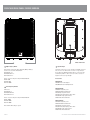
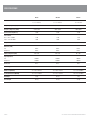
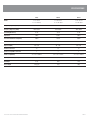
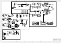
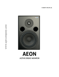
SERVICE INFORMATION
XRS10P
POWERED LOUDSPEAKER
CONTENTS:
OPERATION MANUAL
SCHEMATIC DIAGRAM
Australian Monitor
1 Clyde Street, Silverwater NSW 2128 Australia
+61 2 9647 1411
www.australianmonitor.com.au
XRS SERIES
POWERED AND PASSIVE LOUDSPEAKERS
INSTALLATION AND OPERATION MANUAL
IMPORTANT SAFETY INFORMATION
1.
Save the carton and packing material even if the equipment has
arrived in good condition. Should you ever need to ship the unit, use
only the original factory packing.
2.
Read all documentation before operating your equipment. Retain
all documentation for future reference.
3.
Follow all instructions printed on unit chassis for proper operation.
4.
Do not spill water or other liquids into or on the unit, or operate
the unit while standing in liquid.
5.
Make sure power outlets conform to the power requirements listed
on the back of the unit.
6.
Do not use the unit if the electrical power cord is frayed or broken.
The power supply cords should be routed so that they are not likely
to be walked on or pinched by items placed upon or against them,
paying particular attention to cords and plugs, convenience
receptacles, and the point where they exit from the appliance.
7.
8.
9.
Always operate the unit with the AC ground wire connected to the
electrical system ground. Precautions should be taken so that the
means of grounding of a piece of equipment is not defeated.
Mains voltage must be correct and the same as that printed on the
rear of the unit. Damage caused by connection to improper AC voltage
is not covered by any warranty.
Have gain controls on amplifiers turned down during power-up
to prevent speaker damage if there are high signal levels at the inputs.
10 Power down and disconnect units from mains voltage before making
connections.
13. Do not block fan intake or exhaust ports. Do not operate equipment
on a surface or in an environment which may impede the normal flow
of air around the unit, such as a bed, rug, weathersheet, carpet,
or completely enclosed rack. If the unit is used in an extremely dusty
or smoky environment, the unit should be periodically “blown free”
of foreign matter.
14. Do not remove the cover. Removing the cover will expose you
to potentially dangerous voltages. There are no user serviceable
parts inside.
15. Do not drive the inputs with a signal level greater than that required
to drive equipment to full output.
16. Do not connect the inputs / outputs of amplifiers or consoles to any
other voltage source, such as a battery, mains source, or power supply,
regardless of whether the amplifier or console is turned on or off.
17. Do not run the output of any amplifier channel back into another
channel’s input. Do not parallel- or series-connect an amplifier output
with any other amplifier output. Australian Monitor is not responsible
for damage to loudspeakers for any reason.
18. Do not ground any “hot” (red) terminal. Never connect a “hot” (red)
output to ground or to another “hot” (red) output!
19. Non-use periods: the power cord of equipment should be unplugged
from the outlet when left unused for a long period of time.
20. Service Information Equipment should be serviced by qualified service
personnel when:
A. The power supply cord or the plug has been damaged.
B. Objects have fallen, or liquid has been spilled into the equipment
11. Never hold a power switch in the “ON” position if it won’t stay
there itself!
C. The equipment has been exposed to rain
12. Do not use the unit near stoves, heat registers, radiators, or other heat
producing devices.
D. The equipment does not appear to operate normally, or exhibits a
marked change in performance
E. The equipment has been dropped, or the enclosure damaged.
THIS SAFETY INFORMATION IS OF A GENERAL NATURE AND MAY BE SUPERSEDED BY INSTRUCTIONS CONTAINED WITHIN THIS MANUAL
INTRODUCTION AND CONTENTS
Building on the reliability and sonic quality of the very popular XR speaker
series, Australian Monitor brings you the AM Pro XRS two way injection moulded
speaker enclosures with more features and new aesthetic to suit both live
sound reinforcement and permanent installation. From Front of House to fold
back, the dance floor to background fill, the XRS series with both passive and
powered options are designed with flexibility and performance in mind.
The AM Pro XRS range includes 8”, 10” and 12” models all with high quality
compression drivers and represent a significant advancement in injection
moulded box design while maintaining excellent audio quality and great value
for money.
INTRODUCTION
3
FRONT AND REAR PASSIVE PANEL
4
REAR POWERED PANEL
5
SPECIFICATIONS
6
AUS, EUR, USA
REV A 24th Nov 2008
CAUTION
This symbol is intended to alert the user to the presence of uninsulated
“dangerous voltage” within the products enclosure that may be of sufficient
magnitude to constitute a risk of electric shock to persons.
RISK OF ELECTRIC SHOCK
DO NOT OPEN
CAUTION: TO REDUCE THE RISK OF ELECTRIC SHOCK,
DO NOT REMOVE COVER (OR BACK),
NO USER SERVICEABLE PARTS INSIDE,
REFER SERVICING TO QUALIFIED SERVICE PERSONNEL.
This symbol is intended to alert the user to the presence of important
operational and maintenance (servicing) instructions in the literature
accompanying the appliance.
Caution:
WARNING!
To prevent electric shock do not use this (polarised) plug with an extension
cord, receptacle or other outlet unless the blades can be fully inserted to
prevent blade exposure. To prevent electric shock, match wide blade of
plug to wide slot, fully insert.
TO REDUCE THE RISK OF FIRE OR ELECTRIC SHOCK
DO NOT EXPOSE THIS EQUIPMENT TO RAIN OR MOISTURE.
XRS SERIES INSTALLATION AND OPERATION MANUAL
PAGE 3
FRONT AND REAR PANEL PASSIVE VERSION
1
2
1 High Frequecy Driver
1
XRS8 shown here
1 Speaker Input
Horn loaded compression driver. Directivity 90deg x 90deg.
Passive crossover in the XRS8/10/12.
XRS8/XRS8P 1.5”
XRS10/XRS10P 1.5”
XRS12/XRS12P 2”
The input connector is a 4 pole speakon compatible connector.
Pins 1+ and 1- are wired to the +ve and -ve respectively of
the speaker. The XRS10 and XRS12 have 2 connectors. They
are wired in parallel so either connector can be used as an
input, the other as a loop through.
Active crossover and power amp in XRS8P/10P/12P.
XRS8P 50W
XRS10P 50W
XRS12P 100W
Accessories:
XRS8/XRS8P
XR8PMA Pole mount adapter
XR8UMB Universal mounting bracket
2 Low Frequency Woofer
Driver sizes:
XRS8/XRS8P 8”
XRS10/XRS10P 10”
XRS12/XRS12P 12”
Active crossover and power amp in XRS8P/10P/12P.
XRS8P 100W
XRS10P 100W
XRS12P 300W
Note that the XRS8 ships as a pair.
PAGE 4
XRS10/XRS10P
XR10CVR Heavy duty cover
AMISLSB1 Wall mount brackets
ATC303 Tripod speaker stand
ATC304 Heavy duty tripod speaker stand
ATC305 Winch up speaker stand
XR10-12UB Universal bracket
XRS12/XRS12P
XR12CVR Heavy duty cover
AMISLSB1 Wall mount brackets
ATC303 Tripod speaker stand
ATC304 Heavy duty tripod speaker stand
ATC305 Winch up speaker stand
XR10-12UB Universal bracket
XRS SERIES INSTALLATION AND OPERATION MANUAL
REAR PANEL POWERED VERSION
7 10 2
8 11 4
9 12 6
1 MIC IN
This is a balanced XLR microphone input.
10 Line LEVEL
This controls the level of the LINE input.
(3)
2 Mic SIGNAL
11 Line BASS
This is a green LED signal present
indicator for the Mic input. It indicates
signal present on the input and is not
affected by the level control.
1
3
5
3 LINE IN
This is a balanced XLR line level input.
4 Line SIGNAL
This is a green LED signal present
indicator for the Line input. It indicates
signal present on the input and is not
affected by the level control.
5 LINE OUT
The LINE OUT is on an XLR connector.
This output can be connected to the LINE
IN on another XRS Powered speaker to
expand the system.
6 Output CLIP
This is a red LED clip indicator for the
mixed mic and line audio signal. Some
flashing of red is acceptable on program
transients. Continuous flashing of red
could be placing undue stress on the
speaker and will sound distorted. Turn
down the input level until the clip LED is
no longer lit.
7 Mic LEVEL
15
13 14
This controls the level of the MIC input
(1).
8 Mic BASS
This is the bass control for the MIC input
(1). There is 12dB of cut and boost at
100Hz. This EQ is the shelving type.
9 Mic TREBLE
This is the treble control for the MIC input
(1). There is 10dB of cut and boost at
10kHz. This EQ is the shelving type.
XRS SERIES INSTALLATION AND OPERATION MANUAL
This is the bass control for the LINE input
(3). There is 12dB of cut and boost at
100Hz. This EQ is the shelving type.
12 Line TREBLE
This is the treble control for the LINE
input (3). There is 10dB of cut and boost
at 10kHz. This EQ is the shelving type.
13 Power Switch
This switch turns the power on or off to
the unit.
14 IEC Mains Input Socket
This is a standard IEC 3 pin socket.
It accepts a standard IEC mains cable,
(provided). The fuse draw contains the
mains fuse and a spare.
The mains fuse is a time lag (slow blow)
HRC 20mm x 5mm ceramic or glass type
fuse.
XRS8P
XRS10P
XRS12P
2.5A
2.5A
5.0A
IMPORTANT: Always replace the
fuse with one of the same value and type.
NOTE: Always disconnect power to
the amplifier before replacing fuses.
15 Voltage Select Switch
This switch is used to select the mains
voltage for your region. Select either
230V or 115V.
IMPORTANT: Disconnect power to
the amplifier before operating this switch.
IMPORTANT: Make sure this setting
is correct before connecting the unit to
the mains.
PAGE 5
SPECIFICATIONS
XRS8P
Drivers
XRS10P
XRS12P
1 x 8” woofer
1 x 10” woofer
1 x 12” woofer
1 x 1.5” HF driver
1 x 1.5” HF driver
1 x 2” HF driver
Frequency Response(-3dB)
65Hz-18kHz
55Hz-18kHz
50Hz-18kHz
Frequency Response(-10dB)
55Hz-18kHz
50Hz-18kHz
40Hz-20kHz
118dB
121dB
125dB
Bass control @ 100Hz
12dB
12dB
12dB
Treble control @ 10kHz
10dB
10dB
10dB
100W(low) + 50W(high)
100W(low) + 50W(high)
300W(low) + 100W(high)
Line
0.02%
0.02%
0.02%
Microphone
0.04%
0.04%
0.04%
90° x 90°
90° x 90°
90° x 90°
Peak Sound Level(dB 1m)
Tone controls
Output Power
Distortion (THD)
Tweeter Dispersion(HxV)
Input Impedance
Line
20kOhm
20kOhm
20kOhm
Microphone
10kOhm
10kOhm
10kOhm
Connectors
XLR 3
XLR 3
XLR 3
AC 115V/230V, 50/60Hz
AC 115V/230V, 50/60Hz
AC 115/230V, 50/60Hz
Dimensions(WxDxH)
277 x 265 x 407mm
325 x 308 x 478mm
415 x 391 x 600mm
Packing Dimensions(WxDxH)
355 x 325 x 470mm
375 x 355 x 535mm
465 x 435 x 680mm
Net Weight
8.6kg
10.5kg
23kg
Gross Weight
10.1kg
11.8kg
25.2kg
Power Supply
PAGE 6
XRS SERIES INSTALLATION AND OPERATION MANUAL
SPECIFICATIONS
XRS8
XRS10
XRS12
1 x 8” woofer
1 x 10” woofer
1 x 12” woofer
1 x 1.5” HF driver
1 x 1.5” HF driver
1 x 2” HF driver
Frequency Response(-3dB)
65Hz-18kHz
55Hz-18kHz
50Hz-18kHz
Frequency Response(-10dB)
60Hz-20kHz
50Hz-20kHz
40Hz-20kHz
Sensitivity(dB 1W 1m)
92 dB
95 dB
97 dB
Impedance
8 Ohm
8 Ohm
8 Ohm
Recommended Max Power(Wrms)
100 W
250 W
300 W
Max Sound Level(dB 1m)
118dB
125dB
128dB
90° x 90°
90° x 90°
90° x 90°
1%
1%
1%
1
2
2
Dimensions(WxDxH)
277 x 257 x 400mm
321 x 321 x 464mm
415 x 382 x 620mm
Packing Dimensions(WxDxH)
595 x 310 x 460mm
375 x 355 x 535mm
465 x 435 x 680mm
6.5kg
10kg
18kg
15kg (pair)
12kg
20kg
Drivers
Dispersion(HxV)
Harmonic Distortion
Speakon compatible connectors
Net Weight
Gross Weight
XRS SERIES INSTALLATION AND OPERATION MANUAL
PAGE 7
AUSTRALIA AND NEW ZEALAND
www.australianmonitor.com.au
SYDNEY
MELBOURNE
ADELAIDE
AUCKLAND
(NSW SALES)
(VIC & TAS SALES)
(SA & NT SALES)
(NZ SALES)
1 Clyde Street
Silverwater
NSW 2128
Private Bag 149
Silverwater NSW 1811
Phone: (02) 9647 1411
Fax: (02) 9648 3698
Email:
[email protected]
22/277
Middleborough Road
Box Hill VIC 3128
PO Box 151 Blackburn
South VIC 3130
Phone: (03) 9890 7477
Fax: (03) 9890 7977
Email:
[email protected]
31 Walsh Street
Thebarton
SA 5031
PO Box 157
Hindmarsh SA 5007
Phone: (08) 8352 4444
Fax: (08) 8352 4488
Email:
[email protected]
9C Piermark Drive
Albany 0752
New Zealand
PO Box 300-512
Albany 0752
Phone: (09) 415 9426
Fax: (09) 415 9864
Email:
[email protected]
CANBERRA
BRISBANE
PERTH
(ACT SALES)
(QLD SALES)
(WA SALES)
1st Floor,
Campion Street
Deakin ACT 2600
PO Box 109
Deakin West ACT 2600
Phone: (02) 6260 4544
Fax: (02) 6260 4744
Email: gordon.anderson@
hillssvl.com.au
42 Commercial Road
Fortitude Valley
QLD 4006
PO Box 2578 Fortitude
Valley BC QLD 4006
Phone: (07) 3852 1312
Fax: (07) 3252 1237
Email:
[email protected]
3/11 Howe Street
Osborne Park WA 6017
PO Box 1281
Osborne Park BC
WA 6916
Phone: (08) 9204 0200
Fax: (08) 9244 3783
Email:
[email protected]
EUROPE / ASIA / MIDDLE EAST
www.australianmonitor.com.au
INTERNATIONAL SALES
1 Clyde Street Silverwater NSW 2128 Australia
Private Bag 149 Silverwater NSW 1811
Phone: + 61 2 9647 1411
Fax: + 61 2 9748 2537
Email: [email protected]
1
2
3
4
5
6
7
8
CZ03A
D
C1
10U/25V-NP
CZ01
-15V
GND
+15V
S-IN
LIMIT
XP3
Q1
R19
2K2
XP3
D3
1N4148
2N5551
C9
1U/50V
-15V
R16
R15
1M
R17
10K IC2A
D2
R14
47K IC2B
10K
2
D1
D
C12
22U/50V
C11
22U/50V
6
1N4148
TL074
TJC3-5A
LIMIT
IC3E
V+
V-
IC2E
V+
V-
IC1C
R26
8K213
C16
12
153
IC3D
CV2
104
11
11
4
TL074
CV4
104
2
RP1-1
10K
CV6
104
2
R14
3
10K
R13
1
1
IC2A
JRC4560
D2
1N4148
B
D8
1N4148
-15V
1N4148
TL074
10K
C
6P*100MM(2.5MM)
1
R21
LED1
GREE
JRC4560
10U/25V-NP
C21
22P
440
Q3
C4
473
D9
IN4148
C14
CV5
104
IC3C
8
RP1-1
JRC4560
JRC4560
CV3
104
IC2C
1K5
R29
150K
R6
C11
473
D10
IN4148
R5
R4
10K
15K
C1
+15V
CV1
104
IC1C
Q1
100
2K2
LED3
RED
3
Vout
CV19
CV21
220U/25V 104
~28V
JP3
BR1
KBU-806
CV23
6800U/50V
CV25
470U/50V
CV24
6800U/50V
CV26
470U/50V
CV27
104
CV29
470U/50V
CV31
104
CV18
1000U/35V
GND
Q2
2N5551
2N5401 R23
100K
2
Vin
3
Vout
JP2
CV28
104
CV30
470U/50V
CV32
104
-35V
~28V
IC7
R47
CV20
CV22
220U/25V 104
-15V
7915
CV4
104
440
CV2
-15V
104
+15V
B
Q4
5K1
R3
R26
-15V
R25
R24 3K3
CV8
JRC4560 100U/50V
JRC4560
CV6
LED2 104
GREE
+15V
C13
22P
Vin
+35V
+15V
7815
R27
100K
Earth
JP1
IC6
CV17
1000U/35V
2N5551
10U/25V-NP
R10
30K
R46
10K
C12
22P
1
JP4
R22
OPT1 22P
LCR0202
10K
1
5K1
IC1A
LIMIT
C22
2
1K5
R28
150K
SIN-OUT
2
10K
V+
7
+15V
R12
10K
R42
20K
IC3A
JRC4560
3
C20
R20
4
R8
10K
D8
1N4148
C27
10U/50V
5
TL074
R41
5K1
+15V
IC3B
10K
C19
10U/25V-NP
R11
D5
1N4148 R9
30K
D7
1N4148
C10
10U/25V-NP
1N4148
R44
10PIN2.54mm
5
R19 10K 6
IN2
R4
30K
C6
22P
2
-15V
C9 +15V 3
47P
1
3
2
3
V-
C18
10U/25V-NP
R18
10U/25V-NP
D6
1N4148
10K
1N4007
6
7
4
IN1
R5
CON2
5044
IC3B
47K
10K
2
D4
1
1M
R36
C20
104
IC3A
10K
D5
1
RP2-1
JRC4560
D4
1N4148
-15V
+15V
1M
R35
AC
C7
7
5
560
10U/25V-NP
C8
10U/25V-NP
R7
SIN-OUT
+15V
GND
-15V
1N4148
DZ1
R31
AC
3
R2
2K2
2N5551
1N4148
R20
1M
R32
C26
104
C5
22P
C2 -15V
47P +15V
C3
5P*100MM(2.5MM)
LIMIT
C23
C22
22U/50V
22U/50V
IC1B
D3
1N4148
1
-15V
1
2
3
4
5
6
R33
R45
10/1W
R3
30K
6
2
+15V
10PIN2.54mm
IN1
-15V
-15V
GND
+15V
SIN-OUT
LIMIT
R34
3
560
10K
5
4
3
2
1
D6
GND
CON1
5044
D1
1N4148
RP2-3
-15V
CT01
20K
JP8
JP7
HIGHHIGH+
2
+15V
C1
10U/25V-NP
R1
IC2B
JRC4560
RP1-3
RP1-3
R38
R30
5K6
R37
1
C
22P
IN2
D7
CT01A
1
2
3
4
5
6
7
8
9
10
TL074
R29
6K8
+15V
GND
C15
J1A
8
10U/25V-NP
5
RP2-1
RP2-3
1
2
3
4
5
6
7
8
9
10
153
-35V +35V
4
47
J2A
7
8
R17
3
6
R15
10U/25V-NP
C17
4
47
153
474
8
C19
104
C16
R16
C18
10
JP6
LOW-
IC3C
TL074
Q2
CON3
5040
C17
14
R27
TL074
6K8
153
-15V
TL072
R28
8K2 9
R39
1K2
4
4
8
+15V
C15
C14
2.2U/100VJP9
HIGH A+
1
2
3
4
5
6
7
8
9
10
11
12
13
14
15
C21
CV5
104
C13
104
IC5
TDA7294
TL074
10K
CV3
104
LOW+
R24
10/1W
5
1N4148
+15V
CV1
104
JP5
7
3
1M
R18
474
R21
20K
R13
1
-35V +35V
C10
STBY-GND
ININ+
IN-GND
SUR
BOOTSTRAP
+VS
-VS
STAND-BY
MUTE
NC
NC
+PWVS
OUT
-PWVS
1
2
3
4
5
-15V
R12
15K
+15V
R5
100K 10K
CZ02A
INPUT+
1
2
INPUT3
+15V
1
2
3
TL074
C5
392
C8
1U/50V
C25
10U/50V
R6
R9
15K
C7 TL074
392
R43 51K
TL072
R1 R2
10K 100K
R8
15K
R7
NP-10uF/25V
47K
C2
22P
8
10
R11
15K
C24 10U/50V
6
TL072
R10
14
15K
12
9
1
2
3
4
5
6
7
8
9
10
11
12
13
14
15
C3
7
C6
123
R23
22K
10K
13
R22
1K
1R3
3
IC2C
IC2D
C4
123
R40
22K
R4
100K
IC1B
5
IC1A
2
STBY-GND
ININ+
IN-GND
SUR
BOOTSTRAP
+VS
-VS
STAND-BY
MUTE
NC
NC
+PWVS
OUT
-PWVS
IC4
TDA7294
2N5551
RP3
B50K
7K5
R6
TREBLE
IC4A
JRC4560
7K5
R9
1M
C3
472
J1
OUT1
RP1
22P
2
RP1-3
RP1-1
RP1-3
RP1-1
1
2
3
4
5
6
7
8
9
10
R10
10K
1
6
C4
103
R1
10K
R7
-15V
C6
22P
3
A50K
R2
15K
C5
103
R8
15K
15K
RP2
B50K BASS
7
5
IC4B
JRC4560
+15V
CV7
104
+15V
IC4C
JRC4560
A
-15V
4
A
8
10PIN2.54mm
CV8
104
Australian Monitor
XRS10P
1
2
3
4
5
6
7
8