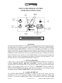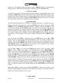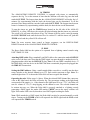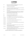
1
ROSCO DELTA 6000™
Operation Manual
Revision 1.0
October, 2004
ROSCO LABORATORIES, INC.
52 Harbor View Avenue, Stamford, CT 06902, USA
(800) ROSCONY, (203) 708-8900, Fax: (203) 708-8919
email: [email protected]
Offices: Hollywood, Toronto, London, Madrid, São Paulo, Sydney
ROSCO DELTA 6000™ FOG MACHINE
OPERATION MANUAL
Information in this document is subject to change without notice and does not represent a commitment on the
part of Rosco Laboratories, Inc.
© 2004 by Rosco Laboratories, Inc.
Edition of October, 2004.
This manual covers the following products:
ROSCO DELTA 6000™ FOG MACHINE
TABLE OF CONTENTS
INTRODUCTION ............................................................................................…2
HOW THE MACHINE WORKS .........................................................................2
IMPORTANT SAFEGUARDS ............................................................................3
GENERAL OPERATING INSTRUCTIONS ......................................................5
DIGITAL/DMX REMOTE INSTRUCTIONS.....................................................7
ANALOG/DMX REMOTE INSTRUCTIONS..................................................10
TIMED REMOTE INSTRUCTIONS.................................................................12
DO'S AND DON'TS ...........................................................................................14
MAINTENANCE ...............................................................................................15
FOG DISTRIBUTION........................................................................................15
ROSCO OFFICES ..............................................................................................16
LIMITED WARRANTY ....................................................................................17
STORAGE AND SHIPMENT ...........................................................................17
DIGITAL/DMX REMOTE MENU FLOWCHART..........................................18
TECHNICAL SPECIFICATIONS .....................................................................19
OPTIONAL ACCESSORIES .............................................................................19
PAGE 1
www.rosco.com
TABLE OF CONTENTS
INTRODUCTION
This manual offers a detailed explanation of the operation of the ROSCO DELTA 6000™ fog
machine. To assure efficient and safe operation, please take a few minutes to read this
material.
The ROSCO DELTA 6000™ fog machine is a thermal aerosol generator designed for very
high variable fog output. It features the DELTA TECHNOLOGY™ which is a revolutionary
electronics design unmatched by any other fog machine. DELTA TECHNOLOGY™ offers
accurate thermal control, precise pump speed as well as allowing the Delta 6000 to be
operated: manually; by timers; from a DMX lighting console; or a 0-10 volt signal.
The Delta 6000 is part of a system, the other basic component being the full line of Rosco fog
fluids. They should always be used together. These unique fluid formulations are safe when
used according to instructions. They are water-based and contain no petroleum distillate. The
operating temperature, pump pressure, and output nozzle orifice of the machine have beeen
specifically set to maximize aerosolization of the Rosco fog fluids. When used properly, the
system should operate for many years.
HOW THE MACHINE WORKS
When the heat exchanger has reached proper operating temperature, the operator switches
power to the siphoning pump, which draws the fog fluid from an external reservoir into the
heat exchanger. The fluid is rapidly heated and vaporized. The vaporized fluid is then
discharged through the nozzle into the atmosphere where, upon mixing with the cooler air, it
turns into an aerosol consisting of millions of fine particles.
NOTE: The terms “fog” and “smoke” are used interchangeably. However the ROSCO
DELTA 6000™ does not produce smoke, but a mist or aerosol.
PAGE 2
www.rosco.com
INTRODUCTION
IMPORTANT SAFEGUARDS
READ AND UNDERSTAND THESE SAFETY PRECAUTIONS BEFORE OPERATING
THE MACHINE. FAILURE TO PROPERLY FOLLOW THESE PRECAUTIONS MAY
LEAD TO A FIRE, EXPLOSION, OR ELECTRICAL SHOCK.
FOG FLUID HEALTH CAUTION: VAPOR FROM THIS FLUID, LIKE ANY OTHER
COMMON MATERIAL IN A VAPORIZED STATE, MAY BE IRRITATING TO OR
CAUSE ALLERGIC SYMPTOMS IN SOME PERSONS WITH ALLERGENIC
SENSITIVITY. DO NOT EXPOSE AT CLOSE RANGE TO KNOWN ASTHMATICS.
1. This machine uses electrical power at common commercially available voltages. When
directly contacted, such voltages are hazardous to human life. All precautions commonly
applicable to the use of electric power generally are applicable to the use of this machine.
This machine is designed to operate from three-wire power systems where one of the wires is
a safety ground. DO NOT disconnect the safety ground or use extension cords or "cheater"
plugs to connect this machine to a two-wire system. Operation without a safety ground may
result in a hazardous electrical shock.
2. Check the current and voltage rating of your machine. Extension cords must be properly
sized and rated for voltage, current and length. Check your local electrical code for the correct
gauge extension cord. If an extension cord shows signs of wear or gets warm to the touch,
discontinue its use and obtain a cord with a higher current rating. Improper extension cords
are not only hazardous, but may result in poor machine performance due to excessive voltage
drop.
3. Never use any machine that shows signs of improper use. Even slight damage may be an
indication of a major problem. If the machine looks questionable, use it only under strict
observation. If the machine shows any unusual behavior, disconnect machine immediately
from power and send machine to a Service Center for repair.
4. Do not operate the machine in a tightly confined space where the ambient temperature
might exceed 135° F (57° C). A continuous flow of air is required to maintain temperature
within the machine housing. Sensitive electronic components deteriorate rapidly under high
heat conditions. Operation of the machine in an enclosure of less than one cubic meter is
dangerous, and automatically voids the warranty.
Enclosing any heating device so it is invisible to the operator creates a potential fire
hazard, no matter what the ambient tempearture of the enclosure. To do so with any
high-amperage device is to assume substantial risk. Rosco strongly recommends against
it.
5. In any facility, the fog concentration should be controlled. The fog should never mask
emergency exits, safety signs, staircases or other safety constructions.
6. After long use, or if the machine is not properly set, some liquid droplets or wet area may
appear in front of the machine’s outlet. This liquid should be wiped up to prevent a condition
where someone might slip and fall.
PAGE 3
www.rosco.com
IMPORTANT SAFEGUARDS
7. Machines are designed for continuous use over an 8-hour day, but to protect components, it
is wise to turn off the machine when it is not in use. In permanent installations, it is advisable
to equip the circuit with a night cut-off device.
8. During the warm-up phase and during operations, people should not stand within three feet
(one meter) of the front of the machine. Flammable material like paper, fabric, etc., should
never be placed directly on or around this equipment, or any other electrical device with a
heating element.
9. The fog should be blown into an open space and should not be directed at people or
objects. Never blow fog on hot surfaces, into glowing heating elements or into open flames.
The normally non-flammable and non-toxic haze could react on very hot surfaces and be
burnt or decomposed.
10. Unauthorized repair or alteration of any safety devices can lead to improper operation and
accidents. Repairs should be performed only by an authorized Service Center.
WARNING: USE OF ANY FLUID OTHER THAN ROSCO FOG FLUIDS OR
MODIFICATION OR ATTEMPTED UNAUTHORIZED REPAIR OF THE ROSCO
DELTA 6000 WILL IMMEDIATELY INVALIDATE THE WARRANTY.
PAGE 4
www.rosco.com
IMPORTANT SAFEGUARDS
GENERAL OPERATING INSTRUCTIONS
OVERVIEW
The Delta 6000 fog machine is a unique fog system that consists of a base unit that can
operate from any of three remote controls. Because of the variation in operability between the
different remotes, there is an operations section for each remote. First follow the General
Operating Instructions and then go to the section for the remote that is being used. If there is
doubt about which remote is being used, please reference the picture in each section.
Note: The ROSCO DELTA 6000 base unit will ONLY operate with one of the remote
controls attached.
1. POWER HOOK-UP
Plug the power cord on the base unit into a socket rated at the proper voltage and amperage.
The machine requires a dedicated power circuit.
Note: If the Delta 6000 was received without a connector on the power cord, please wire an
appropriate connector for the voltage and amperage rating of the machine. The connector
should be wired according to the following wire code: Brown=Hot (Live); Blue=Neutral;
Green/Yellow=Ground (Earth).
2. REMOTE CONTROL
If it is not already plugged in, plug the remote control into the RJ-45 socket in the cavity at
the rear of the base unit marked “Remote Control”. The green LED over the POWER button
should blink indicating that the Delta is receiving power. The Delta 6000 can ONLY operate
with a remote control attached.
Note: The remote attaches with standard computer Category 5 cable using an RJ-45
connection. Although this connection is the same as an ethernet connection, the Delta 6000 is
NOT an ethernet-ready device. Do not try to operate the Delta from an ethernet control.
3. WARM UP
Push the button marked POWER on the remote. This will turn on the electronics and the unit
will start to heat. Let the machine warm up for about ten minutes until the remote indicates
“READY”. The Delta 6000 is now ready to make fog as long as the remote indicates that the
machine is “READY” and there is fluid in the reservoir.
4. FLUID DELIVERY
Place either two 2.5-liter or two 4-liter size bottles of any Rosco fluid in the cavity located at
the rear of the machine. Place the end of each of the tubes coming out of the top of the
machine into each of the bottles. Caps are provided that fit on the bottles. The caps will also
fit a standard 1-liter Rosco bottle. Plug the end of the Low Fluid Sensor into the jack on the
top of the machine.
CAUTION: Both bottles should be the same size and the same type of fluid.
Low Fluid Sensor: The Delta 6000 is equipped with a Low Fluid Sensor. When fluid reaches
a certain point in the bottle the remote will indicate that the fluid is running low. This is
PAGE 5
www.rosco.com
GENERAL INSTRUCTIONS
simply an indication to the operator that the fluid level should be checked and will not affect
the performance. Because the bottles will “self-level” a Low Fluid Sensor is only required in
one bottle.
Pump Cut Off: The Delta 6000 is also equipped with a thermal cut-off that is attached to the
pump. If the machine is running when the fluid bottle is empty, the pump could start to
overheat at which time the thermal sensor will cut off power to the pump. Avoid running the
machine without fog fluid to prevent damage to the pump.
CAUTION: The machine only works with uncontaminated Rosco fog fluids. Other
manufacturers’ fluids may cause spitting and serious clogging problems and could result
in the production of an unhealthful aerosol. The use of other fluids voids the warranty of
the Rosco Delta 6000 fog machine.
5. 0-10 VOLT INPUT
In addition to operating directly from the remote controls and a DMX console, the Rosco
Delta 6000 is also equipped to operate from a 0-10 volt input. The input is located on the rear
of the machine near the DMX connectors. The 0-10 volt input is wired through an RJ-11
connector. Pin 1 is positive and pin 4 is negative. The 0-10 volt input will ONLY operate the
Delta with a remote attached and power turned on at the remote.
6. AIR INPUT
The Delta 6000 is equipped with Air Input located at the rear of the machine. This is to allow
the use of compressed air to clean the heat exchanger. In addition, compressed air can be used
for effects.
PAGE 6
www.rosco.com
GENERAL INSTRUCTIONS
DIGITAL/DMX REMOTE CONTROL
OPERATING INSTRUCTIONS
ARROW
buttons
LCD
display
POWER
button
Jog
wheel
TIMER
button
Fog RUN
button
ENTER
button
Fog MOMENTARY
button
DIGITAL/DMX REMOTE CONTROL
OVERVIEW
The DIGITAL/DMX REMOTE CONTROL is a sophisticated digital interface that allows the
the Delta 6000 to be operated: manually (MANUAL MODE); from timers (TIMER MODE);
from DMX control (DMX MODE); or from a 0-10 volt signal. The interface is a backlit
liquid crystal display (LCD) showing a series of commands. The interface allows the menu to
display in any of six languages (English, French, Spanish, Italian, Portuguese, and German).
In addition, it allows timers to be set in one second increments up to 10 minutes on and one
hour off and has an easy interface to set the DMX channel. It also gives error messages that
indicate when the reservoir is running low on fluid or when there is no DMX signal. To view
the menu structure, see the MENU FLOWCHART on page 18.
7. INITIAL OPERATION
Follow steps 1-4 above. When first powered the DIGITAL/DMX REMOTE will display a
scrolling “ROSCO DELTA 3000 FOG MACHINE” message and then display the
Operation Menu. The Operation Menu is the primary interface for operating the Delta 6000.
While in the Operation Menu, the LCD will give a “HEATING” message. Note: The
DIGITAL/DMX REMOTE will indicate when the fluid container is low on fluid with an
alternating message “LOW FLUID LEVEL” in the Operation Menu.
8. LANGUAGE DISPLAY
The DIGITAL/DMX REMOTE CONTROL is unique in that it can display the menu
commands in any of six languages: English, French, Spanish, Portuguese, Italian, and
German. To access the Language Menu: While in the Operation Menu, push the ENTER
PAGE 7
www.rosco.com
DIGITAL/DMX INSTRUCTIONS
button once. The Language Menu will display. Push an ARROW button to scroll through the
language choices. When the desired language is displayed, push the ENTER button.
9. MANUAL MODE
To produce fog manually: With the Operation Menu displayed, push the RUN button or the
momentary (MOM) button located on the remote control. Push the RUN button again to stop
producing fog. (The momentary button will stop producing fog as soon as it is released.) The
volume of fog can be varied by turning the JOG WHEEL until the desired level is reached.
The output level is listed in 5% increments on the LCD display.
10. TIMER MODE
The DIGITAL/DMX REMOTE CONTROL is equipped with timers. To enable the timers:
With the Operation Menu displaying, push the ENTER button until the LCD reads “SET
TIMERS”. Push an ARROW button until “YES” is blinking. Push the ENTER key. The
LCD will next display the ON TIME settings. This refers to the amount of time that the
machine will make fog. The “minutes” display will be blinking. Turn the JOG WHEEL until
the desired amount of time is displayed (up to 9 minutes). Next push an ARROW button and
the “seconds” display will be blinking. Turn the JOG WHEEL until the desired amount of
seconds (up to 59) is displayed. If you want to change the minutes push an ARROW button
again.
Once the desired ON TIME is displayed, push the ENTER button for the OFF TIME
setting. This refers to the amount of time between bursts of fog. The “minutes” display will be
blinking. Turn the JOG WHEEL until the desired amount of time is displayed (up to 59
minutes). Next push an ARROW button and the “seconds” display will be blinking. Turn the
JOG WHEEL until the desired amount of seconds (up to 59) is displayed. If you want to
change the minutes push an ARROW button again.
Once the OFF TIME is set, push the ENTER button and the LCD will display “SET
DMX?”. Answer “YES” if you wish to set a DMX channel (see below DMX MODE) or
“NO” if you do not. Push the ENTER button. The display will read “SAVE SETTINGS?”.
If you want to keep the timer settings push an ARROW button until “YES” is blinking then
push the ENTER button. If you do not want to keep the timer settings, push an ARROW
button until “NO” is blinking and then push the ENTER button. The LCD will return to the
“SET TIMERS” display. New times can now be entered. Once the settings are saved and the
Operation Menu is displayed, the timer function can be turned on by pushing the TIMER
button on the remote. The yellow LED over the TIMER button will light indicating that the
Delta is in timer mode. When timers are no longer required, simply push the TIMER button
again. To adjust the volume in the TIMER MODE, turn the JOG WHEEL to the desired fog
volume.
Note: When “YES” is chosen in the “SAVE SETTINGS” submenu, the memory in the
DIGITAL/DMX REMOTE CONTROL will remember the settings even when the machine is
turned off or disconnected from a power source.
11. DMX MODE
PAGE 8
www.rosco.com
DIGITAL/DMX INSTRUCTIONS
The Rosco Delta 6000 has the option to be operated from a lighting control console using
USITT DMX 512/1990.
Attaching DMX cable: Plug a standard 5-pin DMX cable to the connection marked DMX IN
at the rear of the base unit. Note that the DMX signal can pass through to another device by
plugging another cable into the DMX OUT plug. Note: Like any DMX controlled device, if
the Delta 6000 is the last device in the DMX line then a terminator plug must be plugged into
the DMX OUT connection.
Setting the DMX address: With the Operation Menu displayed. push the ENTER button
until the “SET DMX” menu is displayed on the LCD. Push an ARROW button so that
“YES” is blinking. Turn the JOG WHEEL until the desired DMX address is displayed. Turn
the JOG WHEEL clockwise to display higher numbers and counterclockwise for lower
numbers. Note: After 512, the channels will go back to 1 so when going from a low number
to a high number, the JOG WHEEL can be turned counterclockwise.
Saving the DMX address: When the desired channel is displayed push the ENTER button
and the LCD will display “SAVE SETTINGS”. To keep the DMX channel settings push an
ARROW button until ”YES” is blinking then push the ENTER button. If the DMX channel
settings are not to be kept, push an ARROW button until NO is blinking. Once the DMX
address is saved, the Delta 6000 will automatically be set to run from DMX.
Operating the unit: With the Operation Menu displayed and the Delta 6000 in DMX mode
(see above), turn the machine on at the remote by pushing the POWER button. Once the
remote reads “READY” and the Delta is in DMX mode, the unit will receive signals from the
lighting console. When the selected channel has a non-zero value at the light board, the Delta
will make fog. The percentage reading at the light board corresponds to the output. (i.e., if the
channel at the light board is set at “75%”, the Delta will run at a volume of 75%.) To stop
fogging, set the channel to zero. The selected channel can be written into any cue.
IMPORTANT NOTE: While in DMX Mode the Delta 6000 can also be operated manually
or, if timers have been set, in the Timer Mode. The Timer Mode will supersede the DMX
Mode and the Manual Mode will supersede the Timer Mode. When “YES” is answered to the
“SAVE SETTINGS?” message, the Digital DMX Remote will only remember the last
settings and will erase any previous settings. To set timers and DMX, both settings must be
entered and then the settings should be saved.
PAGE 9
www.rosco.com
DIGITAL/DMX INSTRUCTIONS
ANALOG/DMX REMOTE CONTROL
OPERATING INSTRUCTIONS
DMX
Rotary Knobs
DMX
LED
POWER
LED
FOG
LED
POWER
Button
TIMER
LED
FOG
Switch
TIMER
Button
ON TIME
Knob
OFF TIME
Knob
VOLUME
Control
ANALOG/DMX REMOTE CONTROL
OVERVIEW
The ANALOG/DMX REMOTE CONTROL is an analog interface that consists of an array of
switches and knobs. These allow the Delta 6000 base unit to be operated: manually; from
timers; from DMX control; or from a 0-10 volt signal. The timers will allow production of fog
for up to 2 minutes with intervals of up to 4 minutes between bursts. It also has a series of
rotary switches to set the DMX channel. In addition, the ANALOG/DMX REMOTE
CONTROL has LEDs that indicate when the reservoir is running low on fluid or when there
is a DMX signal.
12. INITIAL OPERATION
Follow steps 1-4 above. When first powered, the red LED marked “HEATING” will light
indicating that the Delta is heating up. Let the machine warm up until the green “READY”
light is lit. Note: The ANALOG/DMX REMOTE CONTROL will indicate that the fluid
container is low on fluid with a red LED marked “LOW FLUID”.
13. LOCAL OPERATION
To produce fog directly from the remote, push the FOG switch located on the right side of the
remote control. If the upper part of the switch is depressed, the Delta will produce fog until
the switch is returned to the center position. To create fog momentarily, depress the lower part
of the switch. When the switch is released it will automatically return to the center position.
The volume of the fog can be varied by turning the FOG VOLUME knob until the desired
level is reached.
PAGE 10
www.rosco.com
ANALOG/DMX INSTRUCTIONS
14. TIMERS
The ANALOG/DMX REMOTE CONTROL is equipped with timers to automatically
sequence the fog. To set the amount of time that the machine will make fog, turn the knob
marked ON TIME. The longest time that the ANALOG/DMX REMOTE will make fog is 2
minutes. By experimenting with the knob, the desired time can be determined. To set the
amount of time between bursts, turn the knob marked OFF TIME. The longest time between
bursts is 4 minutes. By experimenting with the knob, the desired time can be determined.
To turn the timers on, push the TIMER button located on the left side of the ANALOG
REMOTE. A yellow LED above the switch will light indicating that the timers are activated.
The on/off cycle will start with a burst of fog. The volume of the fog can be varied by turning
the FOG VOLUME knob until the desired level is reached. To turn the timers off, push the
TIMER switch and the yellow LED will turn off.
Note: For more accurate timer control or longer sequences, use the DIGITAL/DMX
REMOTE instead of the ANALOG/DMX REMOTE CONTROL.
15. DMX
The Rosco Delta 6000 has the option to be operated from a lighting control console using
USITT DMX 512/1990.
Attaching DMX cable: Plug a standard 5-pin DMX cable to the connection marked DMX IN
at the rear of the base unit. Note that the DMX signal can pass through to another device by
plugging another cable into the DMX OUT plug. Note: Like any DMX controlled device, if
the Delta 6000 is the last device in the DMX line then a terminator plug must be plugged into
the DMX OUT connection.
Setting the DMX address: Using a small straight blade screwdriver, carefully turn the three
rotary switches to the desired channel up to 512. Each switch represents a digit. Note: If a
number higher than 512 is chosen the Delta 6000 will not recognize the channel.
Operating the unit: Follow steps 1-4 above. When the selected DMX channel has a non-zero
value at the light board, the Delta will make fog. The percentage reading at the light board
corresponds to the output. (i.e., if the channel at the light board is set at “75%”, the Delta will
run at a volume of 75%.) To stop fogging, set the channel to zero. The selected channel can
be written into any cue. When the Delta 6000 is properly attached to a lighting console
generating a DMX signal, the amber LED marked “DMX” next to the rotary switches will
light. If the amber LED is not lit, then there is no DMX signal reaching the Delta.
Note: While attached to a DMX signal, the Delta 6000 can also be operated manually or with
timers. Turning on the TIMER switch will supersede the DMX signal and the FOG switch
will supersede the TIMER switch.
PAGE 11
www.rosco.com
ANALOG/DMX INSTRUCTIONS
TIMED REMOTE CONTROL
OPERATING INSTRUCTIONS
POWER
LED
FOG
LED
POWER
Button
TIMER
LED
FOG
Switch
TIMER
Button
ON TIME
Knob
VOLUME
Control
OFF TIME
Knob
TIMED REMOTE CONTROL
OVERVIEW
The TIMED REMOTE CONTROL is an analog interface that consists of an array of switches
and knobs. These allow the Delta 6000 base unit to be operated: manually; from timers; or
from a 0-10 volt signal. The timers will allow production of fog for up to 2 minutes with
intervals of up to 4 minutes between bursts. In addition, the TIMED REMOTE CONTROL
has LEDs that indicate when the reservoir is running low on fluid.
16. INITIAL OPERATION
Follow steps 1-4 above. When first powered, the red LED marked “HEATING” will light
indicating that the Delta is heating up. Let the machine warm up until the green “READY”
light is lit. Note: The TIMED REMOTE CONTROL will indicate that the fluid container is
low on fluid with a red LED marked “LOW FLUID”.
17. LOCAL OPERATION
To produce fog directly from the remote, push the FOG switch located on the right side of the
remote control. If the upper part of the switch is depressed, the Delta will produce fog until
the switch is returned to the center position. To create fog momentarily, depress the lower part
of the switch. When the switch is released it will automatically return to the center position.
The volume of the fog can be varied by turning the FOG VOLUME knob until the desired
level is reached.
18. TIMERS
PAGE 12
www.rosco.com
TIMED REMOTE INSTRUCTIONS
The TIMED REMOTE CONTROL is equipped with timers to automatically sequence the
fog. To set the amount of time that the machine will make fog, turn the knob marked ON
TIME. The longest time that the TIMED REMOTE will make fog is 2 minutes. By
experimenting with the knob, the desired time can be determined. To set the amount of time
between bursts, turn the knob marked OFF TIME. The longest time between bursts is 4
minutes. By experimenting with the knob, the desired time can be determined.
To turn the timers on, push the TIMER button located on the left side of the ANALOG
REMOTE. A yellow LED above the switch will light indicating that the timers are activated.
The on/off cycle will start with a burst of fog. The volume of the fog can be varied by turning
the FOG VOLUME knob until the desired level is reached. To turn the timers off, push the
TIMER switch and the yellow LED will turn off.
Note: For more accurate timer control or longer sequences, use the DIGITAL/DMX
REMOTE instead of the TIMED REMOTE CONTROL.
PAGE 13
www.rosco.com
TIMED REMOTE INSTRUCTIONS
DO'S & DON'TS
DO
Read the entire manual before operating the machine and pay particular
attention to all CAUTIONS AND WARNINGS.
DO
Use ONLY Rosco brand fog fluids.
DO
Use an extension cord which is properly rated for voltage, current and length
and which is free from nicks or other signs of wear.
DO
Before each operating period, check to see that the machine is clean and free of
foreign objects.
DO
Test first for dry fog.Turn the FOG switch on. Place a piece of cardboard or
paper 18 inches (50 cm) in front of the machine. If the surface is at all wet
return the machine to your dealer for servicing.
DO
Ensure that the machine is adequately ventilated.
DO
Use proper caution when handling hot surfaces
DO
Use the minimum amount of fog required to achieve the desired effect.
DO NOT
Use the machine near a person who has asthma or similar inhalation disorder.
DO NOT
Use any foreign substances in the machine.
DO NOT
Use a machine that is damaged or operating improperly in any way.
DO NOT
Use a machine that leaks fluid from the housing.
DO NOT
Leave the machine switched on for prolonged periods without producing fog.
DO NOT
Enclose the machine.
DO NOT
Install the machine in such a fashion that the operator cannot see the whole
machine including indicator lights.
DO NOT
Touch the shielded nozzle of the machine. Allow sufficient cooling time after
operation before attempting to perform maintenance.
DO NOT
Direct the fog continuously against the same spot. This may eventually cause
fluid to recondense on walls, furniture, sets, etc.
READ THE COMPLETE MANUAL TO INSURE SAFE OPERATION.
PAGE 14
www.rosco.com
DO’S AND DON’TS
MAINTENANCE
1. The main fuse of the ROSCO DELTA 6000 Fog Machine is located on the circuit card
inside the machine. NOTE: Be sure to check the specifications when replacing any fuses.
WARNING: DISCONNECT THE ROSCO DELTA 6000 FROM POWER BEFORE
CHECKING OR REPLACING THE FUSE. FAILURE TO DO SO COULD BE
HAZARDOUS AND RESULT IN AN ELECTRICAL SHOCK.
2. After every operation, the siphon hoses should be removed from the external reservoirs.
The machine should be turned on and fog produced. When there is no more fog coming out of
the machine, the machine should be immediately turned off.
3. Cleaning using air: The best way of keeping the heat exchanger clear of deposits that may
build up is to use compressed air. Blow compressed air through the port at the rear of the
machine marked “Air Input”. The pressure of the compressed air should not exceed 35 psi.
CAUTION: Do not use compressed air until the heat exchanger is free of fluid (see step
#2).
4. After every operation, only after the machine has cooled, it should be wiped with a clean
damp cloth or paper towel. This practice prevents the build up of dirt and dust which may
enter the machine and damage sensitive internal components. Do not use solvents for
cleaning. Soap and water are effective.
5. Before and after the machine is stored for an extended period, the machine should be
properly cleaned. The best method for cleaning is using distilled or de-ionized water. To flush
the machine, turn it on and, when ready to use, put the fluid pick-up tube into a container of
distilled or de-ionized water. Run the water through the machine and flush for three minutes.
The tube should be removed from the water and the machine run until nothing comes out of
the nozzle. The machine should be immediately turned off.
6. During use, operation of all switches and indicator lights should be monitored. Lights that
blink or flicker when they should be on or off, for example, are an indication of problems in
the machine's circuitry.
FOG DISTRIBUTION
The fog distribution in an enclosed area depends on air flow and temperature. Natural air
movement, air conditioning and other ventilation systems will affect movement of fog. Test
under realistic conditions before using. If a space must be filled very quickly, move the
machine up and down and side to side. To conduct fog to particular areas, use a hose adaptor
and ducting hose (see OPTIONAL ACCESSORIES). Make sure that there is an air space of
3-4 in. (5-7.5 cm) between the nozzle and any ducting hose. Do not use ducting hose smaller
than 6 in. (15.25 cm) diameter. The ROSCO DELTA 6000 works properly only in a
horizontal position. Do not tilt the machine during operation.
PAGE 15
www.rosco.com
MAINTENANCE
ROSCO OFFICES WORLDWIDE
If the machine fails and repairs are required, call or write the nearest Rosco office (listed
below) or your local Rosco dealer.
UNITED STATES
World Headquarters
Rosco Laboratories, Inc.
52 Harbor View Avenue
Stamford, CT 06902
(203) 708-8900
(800) 767-2669
E-mail: [email protected]
UNITED KINGDOM
Roscolab, Ltd.
Blanchard Works
Kangley Bridge Road
Sydenham, London
SE26 5AQ England
(81) 659-2300
E-mail: [email protected]
Rosco Laboratories, Inc.
1120 N. Citrus Avenue
Hollywood, CA 90038
(323) 462-2233
(800) 767-2652
SPAIN & PORTUGAL
Rosco Iberica, S.A.
C/Perfumería, Nave 8
P.I. La Mina
28770 Colmenar Viejo
Madrid, Spain
(341) 846-3602
E-mail: [email protected]
Rosco Service Center
1330 30th Street.
Unit G
San Diego, CA 92154
(619) 423-1985
(800) 468-0114
CANADA
Rosco Laboratories, Ltd.
1271 Denison Street #66
Markham, Ontario
Canada L3R 4B5
(905) 475-1400
E-mail: [email protected]
PAGE 16
AUSTRALIA
Rosco Australia Pty Ltd.
42 Sawyer Lane
Artarmon 2064
N.S.W. Australia
(02)9906-6262
E-mail: [email protected]
BRAZIL
Rosco do Brasil Ltda.
Rua Costa, 75
CEP 01304-010
Sao Paulo - SP, Brasil
(011) 259-2111
E-mail: [email protected]
www.rosco.com
ROSCO OFFICES
LIMITED WARRANTY
ROSCO LABORATORIES warrants to the original purchaser that the ROSCO DELTA 6000
FOG MACHINE base unit and any associated remote controls will be free from original
defects in workmanship and material for a period of two (2) years from the date of purchase.
During the warranty period, machines will be repaired or replaced at the option of Rosco.
If the purchaser returns a completed registration card to Rosco within 30 days of purchase,
Rosco will provide free software upgrades to the original owner for the life of the machine.
For more information on software upgrades, please contact the nearest Rosco office.
The warranty does not extend to any parts of the ROSCO DELTA 6000 or the remote controls
that have been subject to misuse or accident. Neither does the warranty cover any machine
that has been opened, modified or repaired other than by Rosco or its designated repair
station.
The warranty will not apply if procedures described in the Instruction Manual are not
followed. It is the user's obligation to clean and maintain the ROSCO DELTA 6000 according
to these instructions, and to follow acceptable practices for handling electrical devices.
NOTE: USE OF ANY FLUID OTHER THAN A ROSCO BRAND FLUID WILL VOID
WARRANTY.
STORAGE AND SHIPMENT
If you do not anticipate using your machine for an extended period, prepare your machine for
storage as follows:
1. Perform maintenance as outlined in "Maintenance" section.
2. Wipe the outside of the machine clean.
3. Store in a sealed cardboard box.
4. Whenever the unit is shipped, considerable care should be taken in packing to avoid
damage in transit.
PAGE 17
www.rosco.com
WARRANTY
DIGITAL/DMX REMOTE CONTROL
MENU FLOWCHART
NOTE: To navigate within a given menu or submenu window (i.e., choosing a language in
the Language Menu) use the ARROW buttons.
OPERATION MENU
ENTER
LANGUAGE
ENTER
SET TIMER?
YES
ON TIME
ENTER
OFF TIME
ENTER
NO
SET DMX?
NO
YES
DMX ADDRESS
ENTER
SAVE SETTINGS?
NO
YES
LEGEND
MENU
SUBMENU
COMMAND
PAGE 18
www.rosco.com
DIGITAL/DMX FLOWCHART
ROSCO DELTA 6000
TECHNICAL SPECIFICATIONS
POWER REQUIREMENTS
120 volts, 60 Hz, 15 amps, 1500W
230 volts, 50 Hz, 10.5 amps, 2400W
PARTICLE SIZE
0.25-60 microns
DIMENSIONS
Height: 9 in. (22.9 cm)
Width: 14.5 in. (36.8 cm)
Length: 25 in. (63.5 cm)
WEIGHT
35 lb. (15.9 kg)
MAX. FLUID CONSUMPTION
193 ml/minute
MAIN FUSE
120 volt: 16A/250v
240 volt: 12A/250v
REMOTE CONTROLS
DIGITAL/DMX REMOTE:
Multi-lingual
Volume Control
Timers
On time: 0:01-9:59 min.
Off time: 0:01-59:59 min.
DMX address
ANALOG/DMX REMOTE:
Volume Control
Timers
On time: up to 2:00 min.
Off time: up to 4:00 min.
DMX address
TIMED REMOTE:
Volume Control
Timers
On time: up to 2:00 min.
Off time: up to 4:00 min.
SECONDARY FUSE
.25A/250v
OPTIONAL ACCESSORIES
HOSE ADAPTOR (200645900006)
Metal frame that connects ducting hose to machine
Dimensions: 6 in. (15.24 cm) x 6 in. (15.24 cm)
DUCTING HOSE (200645950006)
Flexible, plastic hose, connects to hose adaptor for ducting of fog
Dimensions: 6 in. (15.24 cm) x 25 ft. (7.62 m)
PAGE 19
www.rosco.com
SPECIFICATIONS & ACCESSORIES