1
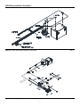
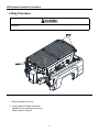
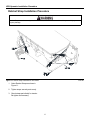
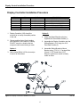
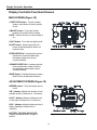
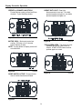
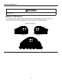
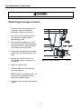
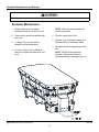
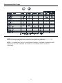
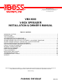
BOSS PRODUCTS
A Division of Northern Star Industries, Inc.
P.O. Box 787 Iron Mountain MI 49801-0787
www.bossplow.com
VBX 8000
V-BOX SPREADER
INSTALLATION & OWNER’S MANUAL
TABLE OF CONTENTS
WARNINGS & CAUTIONS.................................................................................................................................................. 2
INTRODUCTIONS .............................................................................................................................................................. 3
TIPS ON SPREADING ........................................................................................................................................................ 4
VBX WIRING INSTALLATION PROCEDURE....................................................................................................................... 5
VBX SPREADER INSTALLATION PROCEDURE................................................................................................................ 8
SPINNER ASSEMBLY INSTALLATION, ATTACHMENT, & ADJUSTMENT PROCEDURE............................................. 13
SPINNER ASSEMBLY REMOVAL & SWING AWAY / UNLOAD PROCEDURE............................................................... 14
DISPLAY CONTROLLER INSTALLATION PROCEDURE............................................................................................... 15
VBX SPREADER ASSEMBLY DRAWING AND PARTS LIST ......................................................................................... 16
DISPLAY CONTROLLER OPERATION ........................................................................................................................... 18
MATERIAL LOADING PROCEDURE ............................................................................................................................... 21
OPERATING THE SPREADER ........................................................................................................................................ 22
DEFLECTOR ADJUSTMENT ........................................................................................................................................... 23
FINAL ADJUSTMENTS..................................................................................................................................................... 24
MAINTENANCE AND STORAGE ..................................................................................................................................... 26
TROUBLESHOOTING GUIDE .......................................................................................................................................... 28
RECOMMENDED BOLT TORQUE .................................................................................................................................. 30
WARRANTY ...................................................................................................................................................................... 31
BOSS Products / Northern Star Industries, Inc. reserves the right under its continuous product improvement policy to change construction or
design details and furnish equipment when so altered without reference to illustrations or specifications used herein.
Patents Pending
PUSHING THE EDGE
VBS14572
Safety
Serious injury or death can result if you do not follow these instructions and procedures which are
outlined further within your owner’s manual.
Many newer trucks are equipped with air bags. DO NOT under any circumstances
disable or remove or relocate any sensors or other components related to the operation
of the air bags.
Overloading could result in an accident or damage. NEVER exceed the vehicle’s Gross
Vehicle Weight Rating or the Front or Rear Gross Axle Weight Ratings.
This spreader is restricted to the use of dry, free-flowing salt, sand, and sand/salt mix.
NEVER run other materials through the spreader.
DO NOT attempt to mount or remove the spreader with material in it.
Turn spreader off before filling, mounting, removing, servicing, or cleaning.
DO NOT operate spreader within 25 feet of bystanders.
DO NOT climb into or ride on spreader.
Keep hands, feet, and clothing away from moving parts and mounting points.
Spreader must be mounted to vehicle when loading material.
Ratchet Straps must be installed and properly tightened at all times.
Read owner’s manual before operating or servicing spreader.
NEVER store material in hopper.
2
A REVOLUTION AGAINST SNOW & ICE
Congratulations on purchasing the finest V-Box spreader made! The BOSS sets the
standard for quality, reliability, craftsmanship, and performance. Our products are
designed, built, and proven in Michigan’s rugged Upper Peninsula, where winter is a
way of life. And we back it all up with exceptional customer service and satisfaction.
We’re not just setting the standard. We’re leading the way.
The BOSS V-BOX SPREADER has been carefully designed and built for years of
carefree performance.
To keep your BOSS V-BOX SPREADER in top shape, take a few minutes to study this
manual. It will show you how to use and service the BOSS V-BOX SPREADER,
familiarize you with all of its parts, and give you helpful tips on spreading salt and other
materials.
If you have further questions or concerns please contact your local BOSS DEALER.
IMPORTANT
Keep this section for your record.
Date Purchased:________________________________________________
Model Purchased:_______________________________________________
Spreader Serial Number:__________________________________________
PURCHASED FROM
Dealer Name:__________________________________________________
Dealer Address:________________________________________________
Dealer Phone No.:______________________________________________
3
Tips on Spreading
Know the area you are working, hidden obstructions such as curbs, sidewalks, pipes, etc. can cause
damage to your spreader or vehicle.
Do not let the ice build-up; always start as soon as possible.
Always wear your seatbelts when spreading.
Always remember to spread at a safe speed. Spreading faster can be hard on your vehicle as its
load is greatly increased.
NEVER ride on or get body parts into spreader while servicing or operating.
For more spreading tips please visit our website at www.bossplow.com.
4
VBX Wiring Installation Procedure
Wiring Installation Procedure
Before starting any Electrical Wiring Procedure make sure the engine is not running and that the engine has
had sufficient time to cool down. Failure to do so may result in serious bodily injury or death.
Before starting any Electrical Wiring Procedure make sure to disconnect the battery. Failure to do so may
result in serious bodily injury or death.
DO NOT connect ground cable to negative terminal at this time. All wiring should be installed before
completing that step.
Note: This Wiring Installation Procedure is intended for use with the VBX family of slide-in spreaders.
1. Refer to Figure 1 & Figure 2. Begin at
the rear of the vehicle. Secure Molded
Connectors #1 & #2 near the center of
the rear bumper using Cable Ties and
Power/Ground Cable Mount blocks.
8. Replace Cover on Fuse Block.
9. Connect 24” Power Cable to Battery
Positive.
10. Connect Red Fused Tap Spade
Connector #6 to keyed fuse source.
2. Route the harness along the driver side
frame rail and into the engine
compartment. Keep harness away from
hot or moving parts. Secure using Cable
Ties.
11. Connect Red Non-Fused Tap Spade
Connector #5 to CHMSL fuse source if
available.
3. Feed the 4-pin connector (Display
Connector #8) through the firewall, into
the cab, and to a location near the
spreader control. Secure using Cable
Ties (MSC04088).
12. Use provided Scotch Lock to connect
White Bullet Connector #4 to rear taillight ground wire.
13. Use provided Scotch Lock to connect
Brown Bullet Connector #3 to rear
running lamp wire.
4. Install Fuse Block within approximately
12” of battery so Power Cable can be
attached to positive battery terminal and
one side of fuse. Make sure the top of
the block is accessible.
14. Wrap all excess wire and secure in the
engine compartment.
5. Remove Cover from Fuse Block.
15. Secure all wiring to the frame and inside
of the cab using Cable Ties.
6. Connect 5/16” Ring Connector #9 (Red
P/G Cable) to the Fuse Block (make
sure 150 amp fuse is in place).
16. Connect 5/16” Ring Connector #10
(Black P/G Cable) to the Negative
battery terminal.
7. Connect 24” Power Cable to opposite
side of Fuse Block.
5
VBX Wiring Installation Procedure
Figure 1. Vehicle Side Harness Diagram (VBS14283)
G10778
6
VBX Wiring Installation Procedure
Figure 2. Vehicle Side Harness Diagram (VBS14283)
G10777
Figure 3. Full Wiring Diagram
G10779
7
VBX Spreader Installation Procedure
Tie-Down D-Ring Installation
Figure 4. Tie-Down D-Ring Installation
ITEM #
100
101
102
103A
103B
103C
QTY.
4
4
4
8
16
8
G10780
PART #
VBS14547
VBS14549
VBS14550
HDW05854
HDW05859
HDW05995
DESCRIPTION
RATCHET STRAP, 2” X 10’
D-RING
BEDMOUNT PLATE
NYLON LOCK NUT, 3/8”-16, ST/ST
FLAT WASHER, 3/8” ST/ST
HHCS, 3/8”-16 X 1-1/2” STST
1. Mark and drill holes for D-Ring (101)
using 7/16” drill bit.
NOTE: D-Rings should be installed
through or in proximity to frame crossmembers.
2. Using 3/8”-16 X 1-1/2” Hex Head Cap
Screws (103C), 3/8”-16 Nylon Lock Nuts
(103A), 3/8” Flat Washers (103B), and
Bedmount Plates (102), mount D-Rings
to truck in four locations pictured in
Figure 4 & 5. Dimensions are
approximate
Figure 5. Tie-Down D-Ring Dimensions G10801
8
VBX Spreader Installation Procedure
Lifting Procedure
In order to prevent injury or damage to the product, only lift spreader while empty by recommended
lifting points.
Figure 6. Recommended Lifting Points
G10781
1. Remove tailgate from truck.
2. Using installed Lift Bars, lift and set
spreader on the centerline of the truck
bed as shown in Figure 6.
9
VBX Spreader Installation Procedure
Spreader Installation Procedure
Figure 7. Slide Stop Installation
G10782
1. Slide spreader toward cab until Slide
Stop hits truck bed (See Figure 7).
2. Drill four 7/16” holes into truck bed
aligned with Slide Stop holes.
3. Using four 3/8”-16 X 1-1/2” Hex Head
Cap Screw, four 3/8”-16 Nylon Lock
Nuts and sixteen 3/8” Flat Washers,
attach Slide Stop to truck.
4. Rear of spreader must be no closer than
flush with back of truck box (See Figure
8).
5. If step 3 cannot be achieved, refer to
Slide Stop Adjustment procedure on
next page.
6. If step 3 is OK, proceed to Ratchet Strap
Installation.
Figure 8. Spreader Orientation………..G10802
10
VBX Spreader Installation Procedure
Slide Stop Adjustment
1. Slide Stop can be adjusted up to two
inches to make sure the spreader is not
past flush with back of truck box.
2. To adjust, remove 3/8” Carriage bolts
and nuts holding slide stop in place.
3. Slide spreader out to desired position
(1” increments are available). See
Figure 9.
4. Re-install hardware making sure to
tighten securely
Figure 9. Slide Stop Adjustment
G10775
Spacer Installation
1. Measure distance from front of truck box
to spreader legs.
3. For Pintle Chain units, delete the middle
spacer.
2. Build Spacer as pictured in Figure 10
using 2” X 8” boards.
4. Install between spreader and front of
truck box.
Figure 10. Spacer Installation
G10784
11
VBX Spreader Installation Procedure
Ratchet Strap Installation Procedure
Ratchet Straps must be securely attached at all times. Failure to do so could result in personal injury or
property damage.
Figure 11. Ratchet Strap Installation & Orientation
G10785
1. Orient Ratchet Straps as shown in
Figure 11.
2. Tighten straps securely and evenly.
3. Check straps periodically for tension.
Re-tighten as necessary.
12
Spinner Assembly Installation, Attachment, and Adjustment
Spinner Assembly Installation
1. Attach Adjustment Assembly to Spinner
Assembly in position shown using 5/16”
Flat Washers (146) and Thumb Screws
(19). See Figure 12.
Spinner Assembly Attachment
Figure 12. Spinner Assembly
G10771
Figure 13. Spinner Assembly Attach
G10773
Figure 14. Spinner Assembly Adjust
G10772
2. Remove Attachment Pins (18) from
Spinner Assembly.
3. Attach Spinner Assembly to Spreader,
plug in harness, and re-install pins as
shown in Figure 13.
Spinner Assembly Adjustment
4. Spinner Assembly can be adjusted up to
8 inches in 2 inch increments for
vehicles with higher beds. See Figure
14.
NOTE: Unit should be assembled so
height from ground to bottom of spinner
assembly is approximately 24”.
5. Remove two upper Thumb Screws.
While holding Spinner Assembly in
place, loosen lowerThumb Screws.
6. Slide Assembly down to desired height
making sure it rests in bottom of slot.
Re-insert and tighten top Thumb
Screws.
7. Tighten all remaining Thumb Screws.
13
Spinner Assembly Removal and Swing Away / Unload Procedures
In order to prevent injury or damage to the product, the Spinner Assembly must be completely empty when
attaching or detaching it from the vehicle.
In order to prevent injury or damage to the product, the Spinner Assembly must be completely empty when
swinging unit away from spreader.
Spinner Assembly Removal Procedure
1. The Spreader must be STOPPED before
proceeding.
2. Refer to Figure 15. Unplug Spinner
Assembly Harness. Remove Cotter Pins
(17) and Attachment Pins (18)
3. Remove Spinner Assembly.
4. Insert Attachment Pins (18) and Cotter
Pins (17) back into Spinner Assembly for
storage.
Swing Away / Unload Procedure
Figure 15. Spinner Assembly Attach
G10774
Figure 16. Spinner Assembly Attach
G10783
5. The Spreader must be STOPPED before
proceeding.
6. Position Spreader in area where material
is to be deposited.
7. Unplug Spinner Harness, remove Driver
Side Cotter Pin (17) and Attachment Pin
(18).
8. Swing out Spinner Assembly toward
Passenger Side of vehicle. See Figure
16.
NOTE: DO NOT move vehicle at any
time with Spinner Assembly swung out.
9. Push and hold Dump Switch to activate
Spreader and unload material.
10. Swing Spinner Assembly back into place
and re-connect Attachment Pin, Cotter
Pin, and Spinner Harness.
14
Display Control Installation Procedure
Display Controller Installation Procedure
ITEM #
1
2
133
4
130
132
131
QTY.
4
2
2
4
1
1
1
PART #
HDW01766
HDW14462
HDW14463
HDW17833
MSC17827
VBS14460
VBS14461
DESCRIPTION
SCREW,SHEET METAL, 12 X 1/2
CARRIAGE BOLT, ¼-20 X 1/2, ST/ST
THUMB NUT,1/4-20
SCREW,6-19 X ¼ PH PAN
DISPLAY CONTROL
MOUNT BRACKET
SLIDE BRACKET
Option 2:
1. Display Controller (130) should be
mounted to an easily accessible position
in the cab.
4. Attach the Mount Bracket using two
supplied #12 Sheet Metal Screws (1).
2. Choose position that will not interfere
with operation of the vehicle or visibility.
DO NOT mount in a location that an
occupant could contact during a crash.
5. Assemble the Display Controller onto the
Sliding Bracket (131) using four 6-19
Pan Head Screws (4).
Option 1:
6. Assemble Sliding Bracket to Mount
Bracket using ¼”-20 X ½” Carriage Bolts
(2) and ¼”-20 Thumb Nuts (133).
Secure in position so screen is clearly
visible to driver.
3. Use included DUAL LOCK velcro strips
to mount to flat surface.
Figure 17. Display Controller Installation Procedure
G10786
15
Display Controller Operation
Display Controller Functions/Screens
MAIN SCREEN (Figure 18)
START/STOP button: Turns the feeder,
spinner, and vibrator (if active) motors
on/off.
VIBRATE button: Cycles the vibrator
between active and inactive modes.
NOTE: Vibrator will only run when feeder is
on.
LIGHT button: Turns the rear lights on/off.
BLAST button: Sends momentary full
power to feed and spinner motor in 2
second bursts.
Figure 18.
G10787
Figure 19.
G10788
FEED SPEED Dial: Increases feed motor
speed when turned clockwise and
decreases speed when turned
counterclockwise.
SPINNER SPEED Dial: Increases spinner
motor speed when turned clockwise
and decreases speed when turned
counterclockwise.
MODE button: Switches between screens.
(Main Screen & Adjustment Screen)
ADJUSTMENT SCREEN (Figure 19)
BEEPER button: Turns the beeper sound
on/off.
VIB # button: Adjusts the vibration to four
possible levels (4 maximum to 1 minimum)
LIGHT # button: Adjusts brightness level
of rear lights (4 maximum to 1 minimum)
DISP # button: Adjusts brightness level of
display backlight (4 maximum to 1
minimum)
BATTERY VOLTAGE INDICATOR:
Displays estimated battery voltage of
vehicle.
18
Display Controller Operation
Display Controller Indicator Graphics
X: Controller has no communication with
motor control module.
Figure 20.
FEEDER or SPINNER ERROR: Motor is
disconnected or there is a circuit issue.
Error codes come up individually.
G10789
BUTTON STUCK: One of the buttons is
depressed when control is powered up
or stuck down. Will disappear when
condition goes back to normal.
Figure 21.
Figure 23.
G10792
FEEDER or SPINNER JAM:
Feeder/Spinner has encountered an
obstacle and is trying to free itself.
NOTE: DO NOT shut down power to unit
during this time. System is trying to selfclear.
G10790
VIB ERROR: Vibrator is disconnected or
not running properly.
Figure 24.
Figure 22.
G10791
19
G10793
Display Controller Operation
BURNT-OUT LIGHT: Rear light
disconnected or burnt out. One bulb
pictured equals one light out, two bulbs
pictured equals two lights out.
FEEDER or SPINNER JAM STUCK:
Feeder/Spinner could not free itself from
obstacle. Cycle Start/Stop button.
Figure 25.
G10794
Figure 28.
MOTOR COOL: Motor and control are
cooling. Will stay on for 3 minutes
before allowing re-start.
NOTE: Cycling power to display control will
not reset timer.
Figure 26.
TOP SCREEN OPEN: Top screen is open.
Spreader will not run until screen is
closed. START/STOP button must be
pushed again to re-start.
G10795
Figure 29.
DUMP SWITCH ACTIVE: Dump switch at
rear of vehicle has been activated.
Figure 27.
G10797
G10796
20
G10798
Material Loading Procedure
Material Loading Procedure
This spreader is restricted to the use of dry salt, sand, sand/salt, or cinder/salt mix only. Never run
other materials through the spreader.
The spreader must be securely mounted to the vehicle before loading. DO NOT exceed GVWR or
GAWR with spreader and load at any time.
NOTE: These instructions are for recommended vehicle applications only. Go to www.bossplow.com
for more information.
MATERIAL TYPE
WEIGHT RANGE (LBS PER CUBIC YARD)
Fine Salt
Coarse Salt
Coarse Sand (Dry)
Coarse Sand (Damp)
Cinders
1890 - 2160
1215 - 1620
2430 - 2970
2970 - 3510
1080
4. Fill spreader to top of side only. DO
NOT at any time overfill spreader.
Failure to comply could result in
overloading of vehicle and spreader.
1. The spreader must be securely mounted
to the vehicle before loading. Never
attempt to mount a spreader with
material in the hopper.
5. DO NOT exceed GVWR or Front and
Rear GAWR of vehicle when loaded.
2. ALWAYS load spreader with Top Screen
installed and closed. This will prevent
large, impassable, chunks of salt, sand,
or other materials from becoming
clogged in the spreader.
NOTE: For calculating purposes (Spreader
& Load), Spreader empty weight is 600lbs
and struck hopper capacity is 2 yards
(approximate values).
3. Remove tarp before loading.
21
Spreader Operation
Keep hands, feet, and clothing away from moving spinner, auger, chain, and attachment points.
Bystanders to stay a minimum of 25 feet away from operating spreader.
Operating the Spreader
7. Push the Start/Stop button to activate
the spreading system.
1. Start vehicle. Display will light up when
key is turned on.
8. Feed Speed and Spinner Speed can be
adjusted on the fly.
2. Use the Feed Speed Dial and Spinner
Speed Dial to adjust the speed of the
feed motor and spinner motor. This will
dictate how quickly material is pulled
from the hopper and how far it is thrown.
9. You can use the Blast Feature to
momentarily increase the speed of the
Feed and Spinner motors. The motor will
remain at full speed for two seconds and
then pause for two seconds repeatedly
until the Blast button is released.
3. If applicable, turn the vibrator indicator
on (Vibrator will not start until Feed
Motor is activated).
NOTE: Blast feature will only work if
dials are set at less than maximum (10).
4. Access the mode screen and set the
lights and vibrator to their desired level.
10. When finished spreading, always push
the START/STOP button to shut down
the unit.
5. If conditions make it necessary, push
LIGHT button to active rear lights.
6. ALWAYS check for bystanders in and
around unit before starting.
11. Back up to pile, swing out Spinner
Assembly, and actuate the dump switch
to empty the remaining material out of
the hopper if necessary.
Freeing a clog
4. After 3 minutes the START/STOP button
can be pushed again for another attempt
at clearing the unit.
1. When “JAM” appears in either section
indicating that one of the motors are
overloaded, this is most likely due to a
rock or other debris wedged in
auger/pintle or under spinner disk. Do
not turn unit off. System is designed to
try to automatically free itself.
5. If clog cannot be cleared. Disconnect
power at the spreader before attempting
to manually free the unit.
6. When finished using the spreader, back
up to pile, swing out Spinner Assembly,
and actuate the dump switch to empty
the hopper.
2. If you see “JAM STUCK”, the controller
has ceased trying to free itself. Push the
START/STOP button to try again.
3. Repeated unsuccessful attempts will
result in the controller going to a “Motor
Cool” mode. Spreader will not function
for 3 minutes while motors and controller
are cooling down.
NOTE: DO NOT leave material in the
hopper. Failure to empty the spreader
could result in bulged hopper, freeze up,
or other damage.
22
Deflector Adjustment
ALWAYS disconnect Spinner Assembly before adjusting deflector. Failure to do so can result in
personal injury.
Deflector Adjustment
The adjustable plastic deflector can be used to adjust the spread pattern as shown in Figure 30.
The feeder and spinner motor speeds will also have an effect on the spread pattern.
DEFLECTOR EFFECT
DRIVER SIDE
OPEN
PASSENGER SIDE
OPEN
BOTH SIDES
OPEN
Figure 30. Deflector Adjustment
G10287
23
Final Adjustments (If Applicable)
Pintle Chain Restrictor Plate
Figure 31. Restrictor Plate Installation
G10770
Failure to disconnect power to spreader could in personal injury or death.
1. Pintle Chain spreaders are shipped with
a restrictor plate in “Stored” position as
pictured in Figure 31. If flow of spreader
is too fast, install the plate as follows.
7. Remove Restrictor Plate and position
under top plate as shown.
8. Using 3/8”-16 X 1 HHCS and 3/8”-16
Nylon Lock Nuts previously removed,
attach restrictor plate to new position.
2. Disconnect Power/Ground cable and
Main Harness from spreader.
9. Tighten hardware.
3. Remove plastic clips that hold front
cover.
10. Position Cover to be re-attached.
4. Pull cover back and unplug cover
harness from main harness.
11. Connect cover harness back to main
harness.
5. Set Cover aside to be reinstalled later.
12. Attach cover using plastic rivets
previously removed.
6. Remove 3/8”-16 X 1” HHCS and 3/8”-16
Nylon Lock Nuts used to attach
Restrictor plate.
13. Re-connect Power/Ground and Main
Harness cable.
24
Final Adjustments (If Applicable)
Failure to disconnect power to spreader could result in personal injury or death.
Pintle Chain Conveyor Tension
1. The chain comes factory adjusted but
should be checked at installation,
periodically, and prior to each use.
2. Disconnect Power/Ground cable and
main harness to spreader before
performing any work.
3. Check tension by pulling up on chain
two to three feet from Take-Up Bearing.
Chain should come up approximately 1
to 2 inches from conveyor deck.
4. If adjustment is required remove plastic
covers from each side and loosen Jam
Nuts.
5. Working on one side at a time, turn
Take-Up Bolt counter clockwise 1 to 3
revolutions.
Figure 32. Bearing Adjustment
6. Repeat on opposite side.
7. Continue steps 5 and 6 until desired
tension is reached.
NOTE: DO NOT over tighten chain. Too
much tension can cause pre-mature
wear and/or spreader failure.
8. Re-tighten Jam Nuts and replace plastic
covers.
25
G10776
Spreader Maintenance and Storage
Keep hands, feet, and clothing away from moving spinner, auger, chain, and attachment points.
Spreader Maintenance
1. Grease bearings and re-tighten
hardware after every 20 hours of use.
NOTE: Lifting tray from spreader will
require two people.
2. Clean out tray should be emptied after
every use.
5. Remove material from Tray.
6. Replace Tray in spreader making sure
that bolts fall into containment holes.
3. To empty Tray, remove Spinner
Assembly as described earlier.
7. Spreader should be emptied after each
use.
4. Lift up on Clean Out Tray handle to
clear mount holes and slide away from
truck.
NOTE: NEVER leave material in
spreader. Material can freeze or
compact resulting in damage to the unit.
Figure 33. Clean Out Tray Removal
G10799
26
Spreader Maintenance and Storage
Spreader Storage
1. When finished using the spreader, back up to pile, swing out Spinner Assembly, and actuate
Dump Switch to empty hopper.
2. Remove spreader from truck using Lift Bars as described in the installation section.
3. Wash and rinse entire unit.
4. Clean and grease all bearings and chain for storage.
5. Clean all exposed connectors and apply dielectric grease.
6. Remove control from truck and store in clean, dry place.
27
Troubleshooting Guide
Glossary of Problems
1. No power to controller (LED Screen not illuminated).
2. Large X appears on screen, power to controller (LED Screen illuminated).
3. Highlighted battery symbol appears on front screen, power to controller (LED Screen
illuminated).
4. Stuck Button indicator appears on screen, power to controller (LED Screen illuminated).
5. Jam appears on screen
6. Jam Stuck appears on screen
7. Motor Cool appears under Feeder or Spinner on screen.
8. One bulb appears on screen
9. Two bulbs appear on screen
10. Vib. Error appears on screen
11. Error appears under Feeder or Spinner on screen
12. Open Box appears on screen.
13. Feed Motor runs but Auger/Pintle does not turn.
PROBLEM
1. No power to controller
(Display not on).
2. Large X appears on
screen, power to controller
(LED Screen illuminated).
DIAGNOSTIC CHECK
Check battery connections for
corrosion and function.
Check the 2 amp in-line fuse in
the vehicle side harness.
Check that controller is plugged
into vehicle side harness.
Check that spreader side and
vehicle side harnesses are
connected properly.
RESULT
Clean battery connections.
Check that Power/Grou nd plug is
properly connected to spreader.
Remo ve cover and check if green
LED light on module is on.
Connect.
28
Replace fuse.
Connect.
Connect.
Check P/G connection @
bumper and under module.
Troubleshooting Guide
PROBLEM
3. Highlighted battery
symbol appears on front
screen, power to controller
(LED Screen illuminated).
controller.
4. Stuck Button indicator
appears on screen, power to
controller (LED Screen
illuminated).
DIAGNOSTIC CHECK
Check battery and alternator.
RESULT
Re-charge or replace.
Disconnect display controller and
re-connect. Check for repeat of
problem.
Replace.
5. Jam appears on screen.
NA
6. Jam Stuck appears on
screen.
No action required. DO NOT turn
spreader off. Spreader is trying
to free itself.
Spreader has tried to clear itself
unsuccessfully.
Push Start/Stop button to
re-start.
7. Motor Cool appears on
screen.
Circuit that Motor Cool appears in
is resting for 3 minutes.
Push Start/Stop button to
re-start.
8. One burnt out bulb
appears on screen.
Check connections at lights.
Check for burnt out bulbs.
Reconnect or replace.
9. Two burnt out bulbs
appear on screen.
Check connections at lights.
Check for burnt out bulbs.
Reconnect or replace.
10. Vib. Error appears on
screen.
Check connections at vibrators.
Check for malfunctioning vibrator.
Reconnect or replace.
11. Error appears under
Feeder or Spinner on
screen
12. Open box appears on
screen.
Disconnect power and reconnect.
If problem persists, call
local dealer.
Check distance between top
screen latch and plastic plate.
Should not exceed ½”.
Check connection between
gearbox and driveshaft.
Re-position latch or
replace.
13. Feed motor runs but
Auger/Pintle does not
turn.
29
Replace shear bolts.
Recommended Bolt Torque
Figure 34.
G10803
NOTE: The torque values listed above are based on dry, coated bolts, variables such as oil, or other
lubrications may appreciably alter these values and must be taken into consideration.
NOTE: IT IS IMPORTANT THAT ALL FASTENERS BE PROPERLY TORQUED TO ASSURE A SAFE
OPERATING TAILGATE SPREADER. RE-TIGHTEN ALL FASTENERS AFTER 2 HOURS OF
SPREADING.
30
BOSS PRODUCTS
COMMERCIAL WARRANTY
What this warranty covers:
This warranty covers defects in material and workmanship except as set forth below.
Who is covered:
The original purchaser from an authorized dealer.
For how long:
Complete Product: 2 years from the date of purchase.
Labor: 2 years from the date of purchase for complete product.
Parts: 1 year from the date of purchase. (no Labor)
.
What BOSS PRODUCTS will do:
BOSS PRODUCTS will, at its sole option, repair or replace defective parts at no charge.
What you must do for warranty service:
To obtain warranty service, purchaser must return the defective product to any authorized BOSS
PRODUCTS dealer (preferably the one from whom the product was purchased) within the warranty
period. Purchaser must be able to verify the original purchase date. All transportation costs to and
from the dealer will be the responsibility of the purchaser. To locate the authorized BOSS dealer
nearest to you, call toll free: (800) 286-4155.
What is not covered:
1.
Expendable parts such as hoses, plow shoes, cutting edges, pins, nuts, bolts, blade guides, etc.
2.
Products repaired or altered by anyone other than an authorized BOSS PRODUCTS dealer.
3.
Products which have been subject to misuse, negligence, accident, improper installation,
maintenance, care or storage.
4.
Products mounted on vehicles other than those listed in the BOSS SNOWPLOW
APPLICATION CHART AND SELECTION GUIDE.
5.
BOSS PRODUCTS does not assume liability for damage to your motor vehicle resulting
from the attachment or use of any BOSS products. Vehicle risk is the sole responsibility of
the purchaser.
Limits of BOSS Products Liability are:
BOSS PRODUCTS’ LIABILITY IS EXPRESSLY LIMITED TO REPAIR OR REPLACEMENT
OF DEFECTIVE PARTS. BOSS PRODUCTS SHALL NOT BE LIABLE FOR
CONSEQUENTIAL, INCIDENTAL OR CONTINGENT DAMAGES WHATSOEVER, EVEN IF
DAMAGES ARE CAUSED BY THE NEGLIGENCE OR FAULT OF BOSS PRODUCTS.
THE FOREGOING WARRANTIES ARE EXCLUSIVE AND IN LIEU OF ALL OTHER
EXPRESS AND IMPLIED WARRANTIES INCLUDING, BUT NOT LIMITED TO, THE
IMPLIED WARRANTIES OF MERCHANTABILITY AND FITNESS FOR A PARTICULAR
PURPOSE.
This warranty does not apply if you purchased your product for personal, family, or household use.
In this case, refer to the BOSS PRODUCTS Limited Consumer Warranty.
BOSS PRODUCTS is a division of
Northern Star Industries, Inc.
PO Box 787
2010 The BOSS Way
Iron Mountain, MI 49801
(2013-2014)
BOSS PRODUCTS LIMITED
CONSUMER WARRANTY
What the warranty covers:
BOSS PRODUCTS warranties to the original retail purchaser of a BOSS product who purchases it for
personal, family or household use, that the product will be free from defects in material and workmanship
except as set forth below.
Warranty period:
Complete Product: 2 years from the date of purchase.
Labor: 2 years from the date of purchase for product.
Parts: 1 year from the date of purchase. (no Labor)
What BOSS PRODUCTS will do:
If, within the warranty period, the product is found to be defective, BOSS PRODUCTS will repair or replace,
at its sole option, the defective parts at no charge to the original purchaser.
What you must do for warranty service:
To obtain service under this warranty, purchaser must return the defective product to an authorized BOSS
PRODUCTS dealer (preferably the one from whom the product was purchased). The purchaser must establish
the warranty period by verifying the original purchased date. All transportation costs to and from the dealer
will be the responsibility of the purchaser. To locate the authorized BOSS dealer nearest to you, call toll free:
(800) 286-4155.
What is not covered:
1.
Expendable parts such as hoses, plow shoes, cutting edges, pins, nuts, bolts, blade guides, etc.
2.
Products repaired or altered by anyone other than an authorized BOSS PRODUCTS dealer.
3.
Products which have been subject to misuse or service, negligence, accident, improper installation,
maintenance, care or storage.
4.
Products mounted on vehicles other than those listed in the BOSS SNOWPLOW APPLICATION
CHART AND SELECTION GUIDE.
5.
BOSS PRODUCTS does not assume any liability for motor vehicle damage resulting from the
attachment or use of any BOSS products. Vehicle risk is the sole responsibility of the purchaser.
Warranty limitations:
THIS WARRANTY IS OFFERED IN LIEU OF ANY OTHER EXPRESS WARRANTY.
THE DURATION OF ALL IMPLIED WARRANTIES, INCLUDING BUT NOT LIMITED TO THE
IMPLIED WARRANTIES OF MERCHANTABILITY AND FITNESS FOR A PARTICULAR PURPOSE,
ARE LIMITED TO THE DURATION OF THIS WARRANTY.
BOSS PRODUCTS LIABILITY IS EXPRESSLY LIMITED TO THE REPAIR OF THE PRODUCT,
INCLUDING LABOR AND REPLACEMENT OF DEFECTIVE PRODUCT. BOSS PRODUCTS SHALL
NOT BE LIABLE FOR ANY CONSEQUENTIAL, INCIDENTAL OR CONTINGENT DAMAGES
WHATSOEVER, EVEN IF DAMAGES ARE CAUSED BY BOSS PRODUCTS NEGLIGENCE OR
FAULT.
State laws:
Some states do not allow exclusion of incidental or consequential damages or the limitations on how long an
implied warranty lasts, so these limitations or exclusions may not apply to you. This warranty gives you
specific legal rights and you may also have the other rights which vary from state to state.
This warranty does not apply if you purchased your product for other than personal, family, or household use.
If so, refer to the BOSS PRODUCTS Commercial Warranty.
BOSS PRODUCTS is a division of
Northern Star Industries, Inc.
PO Box 787
2010 The BOSS Way
Iron Mountain, MI 49801
(2013-2014)