1
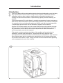
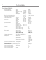
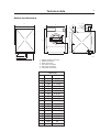
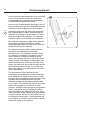
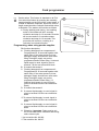
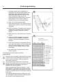
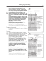
OPERATING & MAINTENANCE MANUAL
FLEX-O-MATIC
EXSM 350
471 1562-95/03
97.44
WARNING: ALL OPERATING AND MAINTENANCE PROCEDURES SHOWN ON THE NEXT
PAGE OF THIS MANUAL MUST BE FOLLOWED DAILY FOR PROPER OPERATION OF
YOUR WASCOMAT MACHINE.
PLEASE ENTER THE FOLLOWING INFORMATION AS IT APPEARS ON THE MACHINE(S)
DATA PLATE(S).
MACHINE TYPE OR MODEL
MACHINE SERIAL NUMBER(S)
ELECTRICAL CHARACTERISTICS: ________ VOLTS, _______ PHASE, _______ HZ.
MAKE CERTAIN TO KEEP THIS MANUAL IN A SECURE PLACE FOR FUTURE
REFERENCE.
II
NOTICE TO: OWNERS, OPERATORS AND DEALERS OF WASCOMAT MACHINES
IMPROPER INSTALLATION AND INADEQUATE MAINTENANCE, POOR HOUSEKEEPING AND WILLFUL
NEGLECT OR BYPASSING OF SAFETY DEVICES MAY RESULT IN SERIOUS ACCIDENTS OR INJURY.
TO ASSURE THE SAFETY OF CUSTOMERS AND/OR OPERATORS OF YOUR MACHINE, THE FOLLOWING MAINTENANCE CHECKS MUST BE PERFORMED ON A DAILY BASIS.
1.
Prior to operation of the machine, check to make certain that all operating instructions and
warning signs are affixed to the machine and legible. (See the following page of this manual
for description and location of the signs.) Missing or illegible ones must be replaced immediately. Be sure you have spare signs and labels available at all times. These can be obtained from your dealer or Wascomat.
2.
Check the door safety interlock, as follows:
(a)
OPEN THE DOOR of the machine and attempt to start in the normal manner:
For FL and EX models, insert a program card, turn the starter knob to the Start
position and place the ON-OFF switch in the ON position.
For HI-TEK microprocessor models, turn the key switch to the RUN position, choose
a program and press the START button.
For SELECTA 28 models, select a wash program and press the Start button.
THE MACHINE(S) SHOULD NOT START !
(b)
CLOSE THE DOOR to start machine operation and, while it is operating, attempt to
open the door without exerting extreme force on the door handle. The door should
remain locked!
If the machine can start with the door open, or can continue to operate with the door
unlocked, the door interlock is no longer operating properly. The machine must be
placed out of order and the interlock immediately repaired or replaced. (See the door
interlock section of the manual.)
3.
DO NOT UNDER ANY CIRCUMSTANCES ATTEMPT TO BYPASS OR REWIRE ANY OF
THE MACHINE SAFETY DEVICES AS THIS CAN RESULT IN SERIOUS ACCIDENTS.
4.
Be sure to keep the machine(s) in proper working order: Follow all maintenance and
safety procedures. Further information regarding machine safety, service and parts can be
obtained from your dealer or from Wascomat through its Teletech Service Telephone - 516/
371-0700.
All requests for assistance must include the model, serial number and electrical characteristics as
they appear on the machine identification plate. Insert this information in the space provided on the
previous page of this manual.
5.
WARNING: DO NOT OPERATE MACHINE(S) WITH SAFETY DEVICES BYPASSED, REWIRED OR
INOPERATIVE! DO NOT OPEN MACHINE DOOR UNTIL DRUM HAS STOPPED ROTATING!
SAFETY AND WARNINGS SIGNS
Replace If Missing Or Illegible
One or more of these signs must be affixed on each machine as indicated, when not included as part of the front instruction panel.
LOCATED ON THE OPERATING INSTRUCTION SIGN OF THE MACHINE:
CAUTION
PRECAUCION
1. Do not open washer door until cycle is completed, operating
light is off, and wash cylinder has stopped rotating.
1. No abra la puerta de la máquina lavadora sino hasta que la
máquina haya terminado su ciclo, la luz operativa esté apaga
da y el cilindro de lavado haya completamento terminado de
girar.
2. Do not tamper with the door safety switch or door lock.
3. Do not attempt to open door or place hands into washer to
remove or add clothes during operation. This can cause
serious injury.
2. No interferia o manipule el switch o la cerradura de la puerta.
MACHINE SHOULD NOT BE USED BY CHILDREN
LAS MÁQUINAS NO DEBEN SER USADAS POR NIÑOS
3. No trate de abrir la puerta o meta las manos dentro de la
máquina para meter o sacar ropa mientras la máquina está
en operación, pues puede resultar seriamento herido.
LOCATED AT THE REAR OF THE MACHINE:
INSTALLATION AND MAINTENANCE WARNINGS
1. This washing machine MUST be securely bolted to an uncovered concret floor
according to the installation instructions to reduce the risk of fire and to prevent
serious injury, or damage to the machine.
2. If installed on a floor of combustible material the floor area below this machine must
be covered by a metal sheet extending to the outer edges of the machine.
3. This washing machine MUST be connected to a dedicated electrical circuit to which
no other lighting unit or general purpose receptacle is connected. Use copper
conductor only.
4. This washing machine MUST be serviced and operated in compliance with manufacturer's instructions. CHECK DOOR LOCKS EVERY DAY FOR PROPER OPERATION
TO PREVENT INJURY OR DAMAGE. IF THE DOOR LOCK FAIL TO OPERATE PROPERLY, PLACE THE MACHINE OUT OF ORDER UNTIL THE PROBLEM IS CORRECTED.
5. Disconnect power prior to any servicing of machine.
6. To remove the top panel for service on those models on which it is secured by screws
at the rear, first remove the screws. Be certain to reinstall them when remounting the
top panel. To remove the top panel for service on those models on which it is secured
by one or two keylocks, use the keys originally shipped in the drum package. Be
certain to relock after remounting the top panel.
MANUFACTURED BY WASCATOR
DISTRIBUTED BY WASCOMAT INWOOD, NEW YORK, USA
LOCATED ON THE DOOR:
If you need to order more safety or warning
signs, call Wascomat's parts department at
516-371-2000, or call your local dealer.
471 76 62 02-02
WARNING !
NEVER USE FORCE ON HANDLE. FOR
SAFETY REASON THE DOOR IS LOCKED
A WHILE AFTER THE DRUM HAS
471 7668 02
STOPPED ROTATING.
FLEX-O-MATIC EXSM 350
Contents
Introduction ...................................................................... 1
Technical data .................................................................. 2
Installation ........................................................................ 4
Safety rules .................................................................... 13
Mechanical and electrical design ................................... 14
Washing instructions ...................................................... 39
Maintenance ................................................................... 41
Trouble-shooting ............................................................ 42
The manufacturer reservs the right to make changes to design and
material specifications.
Safety instructions
• The machine is designed for water washing only.
• The machine must not be used by children.
• All installation operations are to be carried out by qualified
personnel. Licensed personnel are necessary for all electric
power wiring.
• The interlock of the door must be checked daily for proper
operation and must not be bypased.
• All seepage in the system, due to faulty gaskets etc., must be
repaired immediately.
• All service personnel must be fully familiar with the operating
manual before attempting any repair or maintenance of the
machine.
• The machine must not be sprayed with water, otherwise short
circuiting may occur.
• Fabrics softener with volatile or inflammable fluids are not to
be used in the machine.
15
Introduction
1
Introduction
The Flex-O-Matic solid mounted washer/extractor has been developed to cover the heavy
duty requirements of hotels, motels, nursing homes, hospitals, professional laundries,
restaurants, airlines, ships, schools, colleges and all on-premises laundries where
flexibility and quick formula variation, coupled with high quality automatic washing, are
required.
Fig.
1
The card-programmed FL model allows for complete programming of water temperatures,
water levels, wash and extraction periods and supply injections. The machine is designed
for connection to hot and cold water supplies an may be used with free-standing powder
or liquid supply injectors which can be activated by signals from the machine.
All parts of the machine which come into contact with the items being washed are made
of heavy gauge surgical stainless steel, ensuring long life and lasting beauty, as well as
full protection for no-iron fabrics. All electrical components are made accessible for
servicing by simply removing the top panel.
This manual contains a technical description of the machine and instructions for its
installation, operation and maintenance. Together with the wiring diagram which
accompanies each individual machine it should be kept in a safe place for easy reference.
When ordering spare parts or contacting the manufacturer for any purpose always give
the machine serial number, model, voltage and other electrical characteristics appearing
on the nameplate at the rear of the machine.
1
2370b
Technical data
2
Flex-O-Matic EXSM 350
Dry load capacity
up to
Overall dimensions
Width
Depth (at the top)
Height
Net weight
Max. floor load at extraction
Frequency (dynamic force)
80 lbs
1114 mm
1121 mm
1520 mm
645 kg
43 7/8''
44 1/8''
59 7/8''
1422 lbs
±14 kN
10,8 Hz
±3147 lbs.force
Crated Dimensions
Volume
Weight
2.4 m3
662 kgs
85 cu.ft
1460 lbs
Inner drum
Diameter
Depth
Volume
920 mm
520 mm
350 litre
36 1/4''
20 1/2''
12.6 cu.ft.
Speed of rotation
Wash
Distribution
Extraction, low
Extraction, high
40 r.p.m.
60 r.p.m.
325 r.p.m.
650 r.p.m.
G-factor
During wash
During extrac., low
During extrac., high
0.8
55
220
Motor speed
During wash
During distrib.
During extrac., low
During extrac., high
360 r.p.m.
570 r.p.m.
1660 r.p.m.
3380 r.p.m.
Voltage requirements
208-240 V 3-Phase 60 Hz
Rated power
Motor, wash
Motor, distrib.
Motor, extrac., low/high
0.9 kW
1.2 HP
0.95 kW
1.3 HP
4.5/4.8 kW
6.0/6.4 HP
Overcurrent protection, motor Three-phase
25 A
Water connections
Recommended water pressure 2-6 kp/cm2
25-85 psi
Hose connection, water
1''
DN 25 mm
Hose connection, steam
Hose connection, drain
1/2''
75 mm
3''
Technical data
3
Outline and dimensions
C
A
U
4
5
6
S
R
P
1
T
2
B
D
O
L
M
F
G
E
3
N
2479
H
I
K
1
2
3
4
5
6
Electrical cable connection
Steam connection
Drain connection
Hot water connection
Hot water connection
Cold water connection
EXSM 350
A
B
C
D
E
F
G
H
I
K
L
M
N
O
P
R
S
T
U
mm
inches
1114
1520
1206
597
935
66
100
490
590
930
527
120
206
1380
89
184
354
1270
125
43 7/8''
59 7/8
47 15/32''
23 1/2''
36 13/16''
2 5/8''
3 15/16''
19 19/64''
23 1/4''
36 5/8''
20 3/4''
4 3/4''
8 1/8''
54 11/32''
3 1/2''
7 3/16''
13 15/16''
50
4 15/16''
Installation
4
Installation
2
Machine foundation
For making the foundation, check with a
professional engineer in order to calculate
the foundation regarding dynamic and static
forces.
The machines are designed to be bolted in
position to a concrete floor or specially prepared
concrete foundation. A template showing the size
of the foundation and positioning of the foundation
bolts is delivered with each machine.
2396
3
For installation on an existing concrete floor, the
floor must be at least 8'' thick and of good quality.
If the floor does not meet these requirements, then
a 6-8'' high concrete foundation should be made.
Follow the instructions below when making a
concrete foundation:
Fig.
2
Fig.
3
1 Decide where to place the machine and
consider maintenance requirements, i.e.
determine a suitable distance from the rear of
the foundation to the wall, and the distance
from the foundation to the nearest side wall.
The distance should be at least 16 and 2
inches, respectively.
0272
4
2. Break up the floor to a depth of at least 3
inches, making sure that the sides of the hole
slope inwards - the bottom of the hole should
be 5 inches longer than the upper length.
3. Wet the hole well. Brush the bottom and sides
with cement grout.
4. Prepare a casing and fill with concrete to form
foundation. Make sure the foundation is level.
Fig.
4
5. Use the template to position the foundation
bolts correctly - bolts are to extend 1 1/2'' above
concrete.
2397
Reinforcing ironrods A shall be used around the
base. The ironrods shall be placed between the
bolts and the edge of the foundation.
2398
Installation
5
Measurements for foundation in inches and (mm).
Fig.
5
A 42 29/32'' (1090)
H 3'' (77)
B 43 15/64''
K 36 13/16'' (935)
C 3'' (75)
L 37 1/64'' (940)
D 3 15/16'' (100)
M 41 9/16'' (1056)
E 15 23/64'' (390)
N 43 17/32'' (1106)
F 3 15/16'' (100)
O 51 59/64'' (1319)
G 13 25/64'' (340)
P 7/8'' (22)
5
G
F
O
P
B
N
E
M
L
D
K
H
C
Front of machine
A
2340
Installation
6
Mechanical installation
Fig.
6
6
• Place wide steel shims on the concrete
foundation over the bolts.
• Lift the machine and lower it in position. Never
use the door or the door handle to lift or lower
the machine.
Fig.
7
Fig.
8
• Check that the machine is level front-to-rear
and side-to-side and standing firmly on the ten
supporting points. Spacing washers must be
mounted if one or more of these points is not
resting against the floor/foundation.
• Place flat washers over the foundation bolts
and secure the machine in position by
tightening the self-locking nuts, with a torque of
20 kpm.
2400
Torque for the nuts (M16) should be 145 ft lbs.
Fig.
9
7
• Tighten the nuts in sequence as shown.
• Check and tighten the nuts every week for the
first month.
2401
9
8
2399
2402
Installation
Electrical installation
Fig.
10
7
10
Although the machines are fitted with thermal
overloads in the motor windings and separate
fuses for the control circuit, a separate threephase common-trip circuit breaker must be
installed for all three-phase machines.
For proper overcurrent protection, check the data
plate at the rear of the machine. Also consult local
electrical code for special requirements.
Fig.
11
Connect L1, L2, L3 and ground wires according to
the markings of the terminal block. The cable is to
hang in a large loose loop, supported by the clip of
the terminal block. After installation, do the
following:
0277
11
Check the incoming power for a high voltage leg. If
present, connect that line to L2 on the terminal
block.
Fig.
12
Start the machine and check that the drum rotates
in the proper direction during extraction, i.e.
counter-clockwise when seen from the front. If the
drum rotates in the wrong direction interchange
line L1 and L3 at the power connection terminal.
Connection for signals to external liquid supply
injector
Fig.
13
2642a
12
On the right side of the terminal connection is the
connection for signals. Depending on the number
of pumps to be connected, they shall be
connected from 1–5 and C (Common) on resp.
connection. The signal wires can take max. 0,5 A
total output load.
The pumps obtain 220V signals from the program
card via the connections.
Rib A controls connection 1
Rib C controls connection 2
Rib E controls connection 3
Rib G controls connection 4
1760
13
Rib I controls connection 5
NOTE
Remember that it is only a signal which is
obtained from the machine to the pumps and
not time controlling.
From the smaller connection block a power feed of
max 6A output load can be obtained.
2642b
Installation
8
Water connection
14
NOTE
All plumbing must conform to national and
local plumbing codes.
Fig.
14
Fig.
15
Incoming water lines do not require non-return or
back-suction valves, as the machine is already
fitted with a siphon breaker. However, all incoming
lines must be fitted with shut-off valves.
• Water inlets are labelled for connection of hot
and cold water hoses.
2367
15
• Flush the water system thoroughly and check
that the filter at the machine inlet is fitted
correctly.
Fig.
16
• Connect the machine to the water mains with
1'' reinforced rubber hosing not to exceed 6 ft in
length. Hang the hosing in a large loop. Do not
use rigid piping.
Drain connection
Fig.
17
Connect a 3'' (75 mm) flexible hose to the drain
outlet of the machine.
The drain hose must not have any sharp bends
and must slope from the machine to assure proper
drainage. The outlet must open freely to the main
drains or a 6-inch minimum PVC drain line.
2368
16
Do not reduce the size of the drain connection
from the machine to the waste line.
0283
17
1761
Installation
Steam connection
Fig.
18
9
18
The steam inlet pipe must be fitted with a manual
cut-off valve in order to facilitate installation and
service operations.
Attach the filter supplied with the machine to the
manual cut-off valve.
Conncection hoses should be of the quality
required according to regulations in the country
of use.
Connections size at filter: DN 15 (1/2'').
2369
Steam pressure required:
• minimum: 50 kPa (0.5 kp/cm2) (7 psi)
• maximum: 800 kPa (8 kp/cm2) (113 psi)
19
Check there are no sharp angles or bends in the
connection hose.
Connection of top-mount manifold for
connection of external liquid supplies
Remove the cover and cover support from over
the soap box.
Bend all the way back the metal plate in
compartment 3.
1336
Pull the manifold knobs up and forward.
Fig.
19
Fig.
20
Fig.
21
1. Loosen both knobs so that one side of the
metal fingers underneath can slide under the
top lid of the machine, within the supply box.
20
2. Fit the supply manifold into the supply box so
that both sides are held securely in places by
the metal fingers.
Note:
If the supply manifold does not fit, turn it
around. You have it in backwards.
1334
21
1333
Installation
10
Fig.
22
1. Drop the knob into the larger opening in the
supply manifold lid.
22
2. Tighten securely. Do not overtighten! Do not
use pliers or other tools to tighten the knobs!
Fig.
23
1. Stretch the multi-rubber ring B and select the
correct size ring which will fit snugly on the
chemical tube you are using. Ring A is used
for tubes with 5/16'' diam.
2. Use scissors or a razor to carefully cut out the
proper size rubber ring. Wrap the rubber ring
around each tube after threading each tube
through the plastic nipple. Run the tube
through the compression nut to the bottom of
the compartment. Cut the end of the tube at an
angle. Hand tighten the plastic nipple on to the
compression nut.
1332
23
1331
23
Plastic
nipple
Multi-rubber ring
Cut to fit
on tube
Rubber
rings
A
B
Compression
nut
Supply manifold
1331
Start -up and safety checklist
Start-up and safety checklist
11
24
Before initial start-up of a Wascomat washerextractor, the following safety checks must be
performed:
Fig.
24
Fig.
25
• Make sure the machine is properly bolted to the
floor.
• Make sure that all electrical and plumbing
connections have been made in accordance
with applicable local codes.
• Use only flexible water fill and drain hoses of
the proper length to avoid sags and kinks.
• Make sure the machine is properly grounded
electrically.
2399
25
Before the machine is operated, the door safety
interlock must be checked for proper operation as
follows:
Fig.
26
Fig.
27
• When washer loading door is open, the
machine must not start. Verify this by
attempting to start washer with door open.
• When washer is in operation, the loading door
is locked and cannot be opened. Verify this by
attempting to open the loading door when the
machine is operating. If necessary, consult this
manual for proper operation of the door lock
and door safety interlock or call a qualified
serviceman.
1763
26
IMPORTANT:
Door safety interlock must be checked daily
in accordance with above procedure.
WARNING:
Before servicing Wascomat equipment,
disconnect electrical power.
1764
27
1765
Installation
12
Function control check-out list
28
In the machine cylinder, you will find the warranty
registration card, a copy of the warranty policy, the
bolt hole template and other pertinent material.
The warranty card should be completed and sent
to Wascomat. All other items should be placed in a
safe place for future reference.
The machine should be cleaned when the
installation is completed, and checked out as
detailed below without loading the machine with
fabrics:
1. Check the incoming power for proper voltage,
phase and cycles.
2. Open manual shut-off valves to the machine.
3. Turn on electric power.
4. Check the door safety interlock as detailed on
page 11 of this manual.
Fig.
28
0416
29
5. Push the ON-OFF switch to the ''ON'' position.
Turn the programmer knob clockwise and insert
the formula card. Start the machine by now
turning the programmer knob counter
clockwise.
6. Run through a complete cycle, checking for
water temperature and drain operation as cut
on the card.
Fig.
29
7. Machine must spin in a counter-clockwise
direction, as seen from the front, during
extraction. If it does not, reverse lines L1 and
L3.
1760
NOTE
All machines are factory tested prior to
shipment. Occasionally, some residual water
may be found when the machine is installed.
Safety rules
Safety rules
•
The machine is designed for water washing only.
•
Machines must not be used by children.
•
All installation operations are to be carried out by qualified
personnel. Licensed personnel are necessary for all electric
power wiring.
•
The interlock of the door must be checked daily for proper
operation and must not be bypassed.
•
All seepage in the system, due to faulty gaskets etc., must be
repaired immediately.
•
All service personnel must be fully familiar with the operating
manual before attempting any repair or maintenance of the
machine.
•
The machine must not be sprayed with water, otherwise short
circuiting may occur.
•
Fabrics softener with volatile or inflammable fluids are not to be
used in the machine.
13
Mechanical and electrical design
14
General
The door, card programmer, thermometer, thermostat (if heated), control lights and
manual switches are fitted at the front of the machine.
All control and indicating components, i.e. relays, level control, etc are assembled
under the top cover, easily accessible from the top of the machine for ease of
servicing.
Main units
Fig.
30
1 ON-OFF and manual operating buttons - to start the machine and operate it
manually.
2 Card programmer for operating machine through individually programmed cycles.
3 Door - with automatic locking device which remains locked throughout the different
wash processes.
4 Detergent supply box - three compartments for automatic injection of powdered
detergents and fabric softener.
5 Inner cylinder - of stainless steel supported at the rear by two ballraces.
6 Outer drum - of stainless steel (18/8) securely attached to the frame.
7 Wash motor - for reversing wash action and distribution. Extraction motor - for low
and high spin action.
8 Hot and cold water valves - program and level controlled solenoid valves for filling
with water, and for flushdown of detergent supply box.
9 Drain valve - timer controlled valve for draining the machine of water.
10 Siphon breaker - to prevent water in the machine from re-entering the water supply
system.
11 Control circuit - of plug in type, for time and temperature control of the different
wash cycles.
30
2370
Mechanical and electrical design
15
Machine construction
Panels
The machines are equipped with a top panel and front panel made of stainless steel.
For servicing purposes, the panels can easily be removed.
Outer shell
Fig.
31
The outer shell is made of heavy gauge surgical steel and is attached to a heavy duty,
rigid head casting (back gable).
The whole assembly is mounted on a heavy gauge fabricated steel base, hot-dip
galvanized for long life and corrosion resistance.
Inner cylinder
The inner cylinder is made of perforated surgical stainless steel. It is equipped with
three lifting ribs and has highly-polished side sheets and back with maximum
embossed perforated area to assure high flow of water and supplies through fabrics.
Scientifically correct ratio of cylinder diameter and depth assures maximum washing
action.
The shaft is electrically welded to the reinforced back of the cylinder. A specially
designed chromeplated sleeve bushing protects the seals from wear.
31
2370
Mechanical and electrical design
16
Back gable and bearing
Fig.
32
The back gable and the bearing trunnion housing
are constructed of a webbed heavy casting for
extra rigidity. The bearings are protected against
filtration of water by three seals. An intermediate
safety outlet provides an escapement for any
possible condensation.
The seals are mounted on a chrome-plated,
noncorrosive, specially hardened sleeve bushing
that is mounted on the drive shaft to prevent wear
of the seals and shaft. The main bearing is fitted
machinetight into the bearing trunnion housing. A
nut is tightened on the shaft to prevent the cylinder
from moving in and out.
The extension of the bearing trunnion housing
supports the rear bearing holding the shaft. A
grease seal is mounted to prevent escape of
grease. The bearings are permanently lubricated
and need no maintenance.
32
Clamping sleeve
Pulley
Rear bearing
Rotation guard
Bearing housing
Shaft
Back gable
Front bearing
Sealing rings
Bushing
Drum
2371
Mechanical and electrical design
17
Control unit
Fig.
33
All major components for operating the machine, such as card programmer (3) the
thermometer (4) and push-buttons (5) are mounted on the control panel (1) at the front
of the machine.
Components such as relays and reversing timer are mounted in the control unit (2)
located at the top of the machine, easily accessible for service after removing the top
panel.
The control unit is mounted in the machine with 4 screws. Connections to the machine
are made by quick-disconnect plugs. Two thermostats (14) are supplied for heated
machines.
Manual operating switches
Switches with following functions are mounted on the control panel:
Programmer switch
The black knob (6) on the card programmer acts as a main switch for starting and
stopping the machine when washing with a pre-cut formula card. See chapter
’’Operating instructions’’.
ON-OFF switch with signal light (7)
This switch must be in ’’On’’ position with the built-in signal light indicating that there is
power to the machine before the machine can be operated including normal door
opening.
Re-start switch with signal light (8)
is used to re-start the programmer after the buzzer has sounded and the programmer
stopped.
Gentle action switch (9)
is used to obtain a gentle wash action when washing delicate garments. The drum
rotates 3 seconds in one direction, stops for 12 seconds and then operates again for 3
seconds in the opposite direction.
33
1767
Mechanical and electrical design
18
Fig.
34
Drain switch (10)
For manual operation of the drain valve.
Hot water switch (11) and cold water switch (12)
are for manual operation of the inlet valves as marked. When the machine
operates automatically via the programmer, the push-buttons may be used to
raise the water level, by adding water.
Detergent flushing switch (13)
is for manual flushing of detergent from Compartment 1.
Thermostats (14), if heated
Two thermostats controlling two temperatures.
Buzzer and signal light
The buzzer and the yellow signal light (8) are controlled by rib M and may be
programmed to call the attention of the attendant to the machine, at any time
during the cycle to add supplies or unload. To re-start the machine after adding
supplies, press the re-start button.
34
1767
Card programmer
Card programmer
19
35
The EXSM 350 FL-machine is equipped with a
16 track automatic card programmer.
Program cards
Fig.
35
The automatic washing process is controlled by
the plastic program card which is inserted into the
programmer. Any number of cards may be cut to
follow the formulas established by your chemical
supplier for washing, rinsing and extracting needs.
Each card has sixteen ribs, consisting of small
pegs marked A-Q. Each rib controls one wash
function. A step-scale is inscribed on the card so
that a formula of up to 80 steps may be put out on
the card. The programmer advances the card one
peg every 30 seconds, providing a maximum
program time of 40 minutes on a standard card.
Longer cards with 120 steps (60 minutes) are
available.
80 or
120 steps
step
number
16 ribs
G020
20
Card programmer
As the card proceeds through the cycle a missing
peg in one of the ribs closes the circuit of the
corresponding micro-switch in the programmer
and activates that particular function.
36
Never cut the formula without first laying it out on
the card. Mark the pegs to be eliminated and then
carefully re-check it against your formula plan.
Fig.
36
Cutting the pegs from the card is accomplished
with a special pair of cutters, delivered with the
machine, or by using a 1/4 inch chisel. To insure
fault-less programmer operation, it is important
that the pegs be cut off cleanly and completely.
Note that the programmer stops during water fill
and heating (on heated machines). It starts
advancing again when the water level (or pre-set
temperature) has been reached.
The water inlet valves and the drain valve are
electrically interlocked and cannot open
simultaneously. This simplifies the card cutting.
For example, if hot water is required for two or
more consecutive fillings (two washes and a
rinse), the hot water rib may be cut for the entire
length of these three fillings, including drain time.
When the drain valve opens and the water level
drops, the water inlet valves will not open as they
are interlocked with the drain. The moment the
drain valve closes, the required water inlet valve
opens immediately.
The programmer motor which drives the
mechanism is activated only if a water level has
been satisfied or the drain valve is open. During
the water fill, the programmer will not advance the
formula card until sufficient water has been
admitted to satisfy the programmed water level
(low or high). The machine will achieve the proper
water level regardless of variations in water
pressure. During the drain period, the programmer
motor is energized through a separate relay to
keep the programmer advancing the card. If you
call for a buzzer signal (Rib M) when the machine
is empty of water, be sure the drain (Rib K) is cut
to energize the drain valve. The programmer will
thus continue to advance the card until it reaches
the buzzer signal or stop position.
0341
Card programmer
Fig.
37
Gentle action. This feature is standard on all FL’s.
You select this feature by pressing the manually
operated switch on the front of the control panel. It
is ideal for blankets, draperies, slipcovers, and all
fragile materials where reduced mechanical action
is desirable. The washer will function as follows:
A During washing and rinsing, the tumbling
action of the basket will be 3 seconds
clockwise and stop for 12 seconds. Direction
will reverse and run 3 seconds counterclockwise and stop for 12 seconds. This
procedure will continue, resulting in a
reduction in mechanical action.
21
37
Programming, when using powder supplies
Rib function description:
A- Flushing detergent from compartment 1.
Programmed for 30 seconds together with
water filling. If the water pressure is low,
detergent supply should occur after water
filling. Detergent supply can not be
programmed before water filling. If external
liquid supply is used, signal is given to
terminal 1 at the rear connection block.
B- If heated, thermostat 1.
C- Flushing detergent from compartment 2.
Programmed for 30 seconds together with
water filling. If the water pressure is low,
detergent supply should occur after water
filling. Detergent supply can not be
programmed before water filling. (*If
external liquid supply is used, signal is
given to terminal 2 at the rear connection
block).
D- If heated, thermostat 2.
E- If external liquid supply us used, signal is
given to terminal 3 at the rear connection
block.
**F-If external liquid supply is used, signal is
given to terminal 2 at the rear connection
block.
G- If external liquid supply us used, signal is
given to terminal 4 at the rear connection
block.
H- Extraction. Important: Drain must be cut
for 60 seconds before extraction and during
entire extract cycle.
* Up to machine No. 96/196.
** From machine No. 96/197.
0427
22
Card programming
I- Flushing softener from compartment 3.
Programmed for 30 seconds together with
water filling. If the water pressure is low,
detergent supply should occur after water
filling. Detergent supply can not be
programmed before water filling. If external
liquid supply is used, signal is given to
terminal 5 at the rear connection block.
38
K- Drain. Cut for 60 second duration.
L- High speed extraction. Cut together with H if
high speeed is desired. Uncut for low speed
extraction.
M- STOP and buzzer. Programmed if a signal is
desired after completed wash or when it is
desirable to stop in mid-cycle for some
reason.
N- High water level. Will provide low level when
not cut.
O- Cold water filling. Programmed for entire
function period. EXAMPLE: Prewash 2
minutes - cold water programmed for two
minutes.
P- Cool down 3-4°C/min. Programmed directly
after main wash without an intervening drain
period. If external liquid supply is used, P
should be cut for flushing of comp. 2 with
each signal.
Q- Hot water filling. Programmed for entire
function period.
The following must be observed when
programming:
Fig.
38
Fig.
39
Each peg on the program card equals 30 seconds.
(The time unit can be changed to 60 seconds.) To
ensure reliable operation, make sure that the
entire peg is removed.
The program begins with step 0. Cut the peg
before 0 in the same way as 0 to ensure a correct
program start even though the card may be
pushed to far into the controls.
When programming Filling (rib marked O - cold
water and/or Q - hot water, the program controls
stop and start again when the level check provide
a pulse to indicate that the level has been reached
in the drum.
The last pegs that have been cut away (e.g. peg
12) in a program phase determine which peg is to
be removed in the subsequent stage.
0341
39
Rest position
(programmed as row 0)
A. Detergent, (1)
B. Not used (heating)
C. Detergent, (2)
D. Not used (heating)
E. Extern supply
F. Extern supply
G. Extern supply
H. Extraction
I. Fabric softener, (3)
K. Drain
L. High speed extr.
M. Stop with buzzer
N. High level
O. Cold water
P. Cool down
Q. Hot water
1742
Card programming
When Cool down is programmed (rib P) the
machine is filled with cold water. Th amount of
time chosen depends on the temperature desired.
The cooling rate is approximately 3-4°C/min.
Fig.
40
Programming Extraction (rib marked H) shall
always be preceded by Drain (rib marked K). This
shall also be programmed during the entire extract
cycle.
23
40
Extraction
Drain before and
during extraction
A. Detergent, (1)
B. Not used (heating)
C. Detergent, (2)
D. Not used (heating)
E. Extern supply
F. Extern supply
G. Extern supply
H. Extraction
I. Fabric softener, (3)
K. Drain
L. High speed extr.
M. Stop with buzzer
N. High level
O. Cold water
P. Cool down
Q. Hot water
Programming Stop with signal (rib marked M) can
be carried out several times during the same wash
program. When the program comes to Stop, a
buzzer sounds and the machine stops. Press
RESTART to restart the machine.
RESTART may not be used without having a
program card inserted in the machine.
Use ribs C, I, A, E and G for signals when
connecting external supply dispensing equipment.
Programming example
A card which is programmed for normal soiled was
as follows:
Pre-wash
Fig.
41
The pre-wash lasts for approximately 3 minutes
(peg nos. 0 to 6) and begins with Filling with cold
water and hot water to a high water level and
dispensing of detergent from compartment 1 (peg
no. 0 in ribs N, A, O and Q cut away).
Ribs N, A, O and Q are cut at peg no. 1 as a
safety measure to ensure that the wash cycle is
correct even though the program card may be
pushed too far into the program controls.
The programmer stops the card at peg no. 0 until
the water level is reached. The running time once
the water level and required temperature are
reached is 2 minutes (peg nos. 1-5 cut away in
ribs N, O and Q).
Ribs B, I and Q are cut away for the entire
prewash to ensure that the temperature and water
level are maintained during the entire wash
sequence. It is usually necessary to top up with
water since the dry wash goods soak up a certain
amount.
The pre-wash is concluded with Drain for one
minute (peg nos. 5 and 6 in rib K cut away).
1743
41
Filling with water
and detergent
Washing
Draining
Rest position
(programmed as row 0)
A. Detergent, (1)
B. Not used (heating)
C. Detergent, (2)
D. Not used (heating)
E. Extern supply
F. Extern supply
G. Extern supply
H. Extraction
I. Fabric softener, (3)
K. Drain
L. High speed extr.
M. Stop with buzzer
N. High level
O. Cold water
P. Cool down
Q. Hot water
1744
Card programming
24
Main wash
Fig.
42
The main wash lasts for approximately 8 minutes
and begins by filling with hot water and dispensing
detergent from compartment 2 (peg no. 8 in rib C
cut away).
42
Draining
Washing
Filling with water and
detergent
The programmer stops the card at peg no. 8 until
the water level is reached.
A. Detergent, (1)
B. Not used (heating)
C. Detergent, (2)
D. Not used (heating)
E. Extern supply
F. Extern supply
G. Extern supply
H. Extraction
I. Fabric softener, (3)
K. Drain
L. High speed extr.
M. Stop with buzzer
N. High level
O. Cold water
P. Cool down
Q. Hot water
Rib Q is cut away for the entire main wash to
ensure that the water level is maintained during
the entire wash procedure. The running time once
the required level has been reached is 6 minutes
(peg nos. 8-23 removed from rib Q).
The main wash is concluded with Drain for one
minute (peg nos. 24 and 25 in rib D removed).
Rinse cycles 1-3
Fig.
43
Rinse cycles 1-3 each last for approximately 2
minutes and are identical. The following descibes
rinse cycle 1. The rinse cycle begins with Filling
with cold water to high level (peg nos. 26-29 in ribs
N and Q are cut away).
The programmer stops the card at peg 26 until the
water level is reached. The running time once the
water level is reached is 2 minutes.
The rinse cycle is concluded with Drain for 1.5
minutes and with extraction for the last 30 seconds
(peg nos. 30-32 in rib K and peg no. 32 in rib H
removed).
Rib K must always be programmed parallel with rib
H to achieve the extraction cycle. SInce extraction
must not be operated with the drum filled with
water, rib K (Drain) is programmed 2 pegs earlier
that the extraction cycle to drain the water before
the extraction cycle starts. The machine also has a
level guard to ensure that the extraction cycle
cannot start while there is water in the drum.
1745
43
Rinse 1
Extraction
Draining
Rinse 2
Rinse 3
Filling with water
and fabric
conditioner
A. Detergent, (1)
B. Not used (heating)
C. Detergent, (2)
D. Not used (heating)
E. Extern supply
F. Extern supply
G. Extern supply
H. Extraction
I. Fabric softener, (3)
K. Drain
L. High speed extr.
M. Stop with buzzer
N. High level
O. Cold water
P. Cool down
Q. Hot water
1746
Card programming
Rinse cycle 4
Fig.
44
Rinse cycle 4 lasts for 8 minutes and begins with
Filling water to high water level and dispensing of
fabric conditioner from compartment 3 (peg no. 33
in ribs N, I and O removed).
The programmer stops the card at peg 33 until the
water level has been reached. The running time
once the water level has been reached is 2
minutes (peg nos. 33 to 36 in tibs N and O cut
away).
Rinse cycle 4 is concluded with Drain for 6
minutes (peg nos. 37-50 in rib K cut away). When
Drain has been in operation for 1 minute, the
extraction cycle starts and lasts for 5 minutes (peg
nos. 29-48 removed from rib H).
Ending the program
The washing process is completed by removing
peg no. 51 from rib M (stop with signal). The stop
is indicated by a buzzer and the yellow indicator
light in the RESTART button coming on.
25
44
Draining
Stop with
signal Extraction
Tumbling
Rinsing
Filling with
water
and fabric
conditioner
A. Detergent, (1)
B. Not used (heating)
C. Detergent, (2)
D. Not used (heating)
E. Extern supply
F. Extern supply
G. Extern supply
H. Extraction
I. Fabric softener, (3)
K. Drain
L. High speed extr.
M. Stop with buzzer
N. High level
O. Cold water
P. Cool down
Q. Hot water
1747
Mechanical and electrical design
26
Replacement and adjustment of micro switches
Fig.
45
After removing the two wire connection sockets at the top of the programmer,
remove the two screws holding back the black cover plate over the microswitches
and the plate (A). Turn the knob. Lift up the defective microswitch and replace it
by a new one. Mount the cover plate.
A special test card is used to check and correct the adjustment of the card
programmer microswitches.
Coloured dots indicate various positions on the card.
Please follow the instructions shown below when using this testcard to adjust the
programmer microswitches:
1. Turn the knob fully clockwise and insert the card into the programmer with the
track side up and the unnumbered side first, until the green dot one card is
even with the front edge of the programmer.
2. Turn the knob fully counter-clockwise and push the card in until the blue dot is
even with the front edge.
Check that all microswitches make contact between the blue and white dot.
Readjust if necessary by using a thin screwdriver on the individual adjustment
screws.
3. Slide the card out until the green dot is even with the front edge. Check that no
switches have switched contact to this pint. Adjust if necessary.
4. Slide the card further out until the blue dot is even with front edge. Check that
all microswitches have now switched over. Readjust if necessary.
This procedure should be repeated at least twice to make certain that the
switches are all properly adjusted.
45
0420
Mechanical and electrical design
Reverser
27
46
Construction of reverser
Fig.
46
The reversing switch unit consists of a camshaft
(6) and a contact bank (5) with two alternating sets
of contacts and three sets of opening contact all
made of silver. The cam shaft is driven by a
synchronous motor (2) via an escapement (1). The
gears are made of durable plastic to ensure a long
life. The contact bank is made of plastic (Melamin)
resitant to current.
The reversing switch is assembled by means of a
mounting pin (8) and three spacer pins (7), which
automatically give the correct distances. To
replace the contact bank, only the mounting pin
and one spacer pin need to be removed.
0421
Operation of reverser
Fig.
47
During reversing, the drive motor is without current
to avoid burning contacts in the reversing switch.
This is achieved by energizing the wash motor
relay via contact 1b or 2b, by cutting out the
current 1 1/2 seconds before contacts 4 and 5
change over and not engaging the wash motor
relay until 1 1/2 seconds after changeover. See
sequence diagram. Normal reversing action 12/3,
gentle action 3/12 seconds.
47
0422
Mechanical and electrical design
28
Relays
48
The FL model employs seven relays. The relays
control:
• the wash windings of the wash motor
• the distribution windings of the wash motor
• the extraction motor
• the drain cycle
• the restart after a programmed stop
• the switching back to low speed extraction if too
high unbalance is indicated.
Construction
Fig.
48
The body of the relay holding the stationary
contacts is made of current-resistant plastic. A
solenoid and a contact bank hold the moving
contacts. The contacts are spring-loaded to assure
the correct contact pressure.
The relay is constructed for continuous operation,
whether mounted horizontally or vertically.
Screw-type terminals provide perfect connections
even when one or two wires have different
diameters.
Operation
When the solenoid is energized, the two halves of
the magnet core are drawn together, pulling down
the moving contacts, thus making or breaking the
circuit. When the current cuts out, springs force
the contact bank into its original position, thus
closing or opening the circuits.
Trouble shooting
If the relay fails to operate despite power to the
coil, turn off the power and check the solenoid by
measuring the resistance across the terminals (1).
If the relay hums when power is applied, this
indicates either a break in the insulator holding the
moving contacts at the axle where it holds the top
half of core (3) or a rusty core (4), which can be
cleaned.
Make sure that the moving contact assembly
moves freely. Always replace burnt or pitted
contacts (2) ... do not reuse contacts.
0301
Mechanical and electrical design
Drive motors
29
49
Drive motor description
Fig.
49
The four-speed operation of the wash cylinder is
achieved by two motors. One 2-speed motor for
wash speed (12-pole drive) and distribution speed
(8-pole drive) and one 2-speed motor for
extraction speeds (4-pole drive, low speed and
2-pole, high speed). The motors are mounted on a
motor bracket with the wash and distribution motor
fixed to the bracket and the extract motor in slots
which allow adjusting the distance between the
two motors for proper belt tension by adjusting
screws. For silent operation the motor bracket is
mounted to the base of the machine by rubber
bushings. Correct tension to the main belt,
between the cylinder and the extract motor, is
obtained by the weight of the motors and the
motor bracket and by the spring loaded set screw.
Drive motor construction
The motor consists of stator, rotor and end-shields
with ball-bearings. The stator and the rotor
consists of plates, insulated from each other and
welded together. The stator is provided with slots
in which the 8-pole and 12-pole resp. the 2- and
4-pole windings are wound. The windings are
impregnated with a temperature-resistant soundinsulating resin varnish according to class B. The
end-shields are die-cast. The ball bearings are
permanently lubricated.
2372
30
Mechanical and electrical design
Drive motor function
50
When the stator winding is charged, a magnetic
field will occur, which in turn will rotate the motor at
a fixed RPM depending upon the number of poles
in the winding. The 12-pole winding gives the
wash speed and the 8-pole winding in the same
motor gives the distribution speed. The separate
4/2-pole motor gives the extraction speeds. When
operating with load, the speed deviates slightly
from the synchronous (no-load) speed. This
difference is called the slip and is usually
expressed as a percentage of the synchronous
speed. The motors will work satisfactory at
nominal voltage +10% – -15%.
How to remove motors
Fig.
50
Loosen the spring loaded set screw. Lift the motor
unit and detach the V-belts. Dismount the bracket
holding the motor hinge shaft. Lift out the motor
bracket with motors mounted. Loosen the
mounting screws of the extract motor and the set
screws. Lift off the V-belts. Now remove the
mounting screws for each motor.
How to mount motors
Place the motors on the table or bench with the
mounting holes upwards. Mount the mounting
bracket to the wash/distributiont motor. Position
the other motor and fasting the mounting screws.
Mount the V-belts. Tighten the belts. Mount the
bracket with motors in the machine in the opposite
way as outlined above in ’’How to remove motors’’.
2403
Mechanical and electrical design
Motor connections
Fig.
31
51
Wash/distribution motor
51
Fig.
Extract motor
Thermal Overload protector
52
Motor overload protector
Each motor is equipped with self-resetting, thermal
overload protectors, situated one in each winding
of the stator. The protectors are connected in
series and will trip at a temperature of 120°C
(248°F). In the event the protectors fail but the
motor remains otherwise undamaged, an overload
protector may be mounted in the control unit of the
machine. Before making such installation check to
ascertain that the windings are not damaged.
NOTE
Before connecting a separate overload
protector consult the Wascomat Teletech
Service.
51a
52
Thermal Overload protector
51b
Mechanical and electrical design
32
Repair instructions
53
Motor not running due to overheating
• Wait till motor has cooled down. Motor thermal
protectors are automatically reset after appr. 30
minutes. Restart.
• Possible cause of motor protector releasing
repeatedly could be oversensitivity of thermal
protector.
111 lbt
25 N
Very noisy motor
14 mm
9/16''
• Breakdown of bearings – replace bearings or
motor.
Motor running slowly
• The motor is probably running on two phases –
measure voltage at output of relay and at
connection block.
Wash motor only runs at one of the speeds
• Check that the quick connection is correctly
connected.
• Check that correct relay is being energized.
Motor locks
• Breakdown of bearings – replace bearing or
motor.
Motor does not turn
•
Check electrical power to motor.
Drum does not turn
• Check belt tension.
Tensioning of the V-belt
Fig.
53
• Belt between the wash motor and extract motor
- release and adjust backing plate to correct
belt tension according to illustration. Fasten
plate.
• Belt between extract motor and drum
- remove screws for the attachment of motor
bridge at extract motor side, lower motor
bridge to correct belt tension according to
illustration and fasten bridge.
9 mm
3/8''
111 lbt
25 N
2385
Mechanical and electrical design
Water level controls
Fig.
54
33
54
One double-level pressure switch is used to
control the correct water levels during various
cycles of the washing program.
A second level control is installed on the machines
to prevent the machine from going into extraction
until a sufficient amount of water has been
drained.
A third level control is instaled to prevent flushing
down the soap supply box before a low level is
reached.
Adjustment
All pressure switches are factory-calibrated to
meet specific requirements. The trip level for any
one pressure switch can be changed only within
narrow limits because each trip range requires a
different set of springs.
Water level
As a guide for checking the level control for proper
functioning, the low level should be at the bottom
of the door glass, and the high level approximately
three inches above it.
0305
Mechanical and electrical design
34
Supply injection valve
55
Construction
Fig.
55
The valve has a single-inlet with either one, two
or three outlets, each with its own solenoid coil.
The body is made of heat-resistant polyamid
plastic and the solenoids encased in water-tight
plastic. The electrical connector terminals are
spade lugs.
A filter screen on the inlet side prevents dirt from
entering the valve. Flow restrictors can be
placed at either the inlet or any of the outlets.
Operation
Fig.
56
When the solenoid is energized, the springloaded plunger is drawn up and the pilot valve in
the centre of the diaphragm open. Because of
the difference in diameter between the pilot
valve opening and the ventilating hole in the
diaphragm, the pressure above the diaphragm
drops to a point where the admission pressure
below the diaphragm can lift the diaphragm, thus
opening the valve.
0306
56
When the current to the solenoid is cut off, the
plunger spring will press the plunger against the
pilot opening of the diaphragm. The pressure
above the diaphragm then rises to correspond to
the water inlet pressure and the pressure of the
spring will close the valve.
0307
Mechanical and electrical design
Repair instructions
35
57
Limescale can block the hole in the valve
diaphragm and interfere with the function of the
valve.
Fig.
57
It is therefore advisable to dismantle and clean the
valve at certain regular intervals. The frequency
depends on operating conditions and the level of
contamination in the water.
If the valve does not open
• Check that power is supplied to the coil.
• Check the coil with an instrument to determine
whether there is a break or a short circuit.
• Dismantle the valve (see below) and check the
openings in the valve diaphragm.
• Check the inlet strainer and clean as required.
0308
58
• Undo the coil and clean the surfaces of the
magnetic core.
If the valve does not close
• Check that the coil is not live. The valve is
normally closed when the magnet is not
energised.
• Check the return spring.
• Check the diaphragm (pilot pressure opening).
Dismantling the valve.
Fig.
58
Fig.
59
• Pull the coil straight upwards. Use a
screwdriver if necessary to carefully undo the
coil.
• Use the tool supplied (attached to one of the
hoses when the machine is delivered) to open
the valve housing. Slide the tool over the
protruding plastic sleeve to that the pegs on the
tool engage the corresponding sockets in the
valve housing.
0309
59
• Use a spanner or a pair of pliers and unscrew
the upper part of the valve housing.
0310
Mechanical and electrical design
36
Inlet valve for FLEX-O-MATIC
EXSM 350
Fig.
60
60
The water inlets have brass bodies with larger
cross section of the outlet in order to achieve a
shorter filling time for the machine.
Construction
Fig.
61
The valve housing is made of pressed brass. The
spring-loaded plunger is made of stainless steel
and located at its lower end.
Operation
The valve is automatically operated by means of
a rubber diaphragm and a pilot valve in exactly
the same way as the supply injector valve.
NOTE: To strip, clean, re-assemble and
troubleshoot the inlet valve, follow the
instructions outlined for the supply injector
valve.
3963
61
Coil
Spring
Plunger
Body
Diaphragm
3961
Mechanical and electrical design
Drain valve
37
62
Description
Fig.
62
The drain valve is operated by using the pressure
in the cold water intake. A tube (1) is connected
between the cold water intake and a solenoid
valve (2). When the solenoid valve is activated, it
opens and allows water to flow into the feeder tube
(3). The water presses up a piston (4), which uses
the pressure lid (5) to close the drain valve rubber
membrane. When the solenoid valve cuts out, the
water pressure and the springs (7) on the lid push
the piston back, allowing the water to pass the
solenoid valve and drain out via the return tube
(8).
Trouble shooting
If the drain valve doesn’t close:
• Check that the solenoid valve (2) receives
electricity.
• Check that the solenoid valve and the tubes are
clear by:
- removing the drain hose (3).
- Check that water exits the hose when the
valve is activated.
• Check that the diaphragm (9) is undamaged.
If the drain valve doesn’t open:
• Check that the return tube (8) is open.
• Check that the piston (4) doesn’t seize.
2404
Mechanical and electrical design
38
Soap supply box
Fig.
63
The three-compartment soap supply box is located at the top of the machine.
Viewed from the front, the compartments marked with figures 1, 2 and 3 are used
as follows:
For powder supplies:
Compartment 1
This compartment is used for adding detergent directly to the wash at the
beginning of a cycle or at any time during the cycle when extra supplies are
required, controlled by rib A on the formula card.
Compartment 2
This compartment is the main compartment for adding detergent to the wash
when called for by Rib C on the formula card.
Compartment 3
The small compartment is used for adding fabric softener. The fabric softener is
flushed down with water by overflowing when the injection of fabric softener is
called by rib I on the formula card.
For liquid supply with top mount supply connection:
All supplies are injected through compartment 2. Flushdown is controlled by rib P.
63
1182
Mechanical and electrical design
39
Door and safety locking system
The door safety locking device consists of the following main parts:
Fig.
64
• Locking unit. The door locking unit is placed behind the front plate and
under the detergent box. The unit consist of a coil, which blocks the
door, and two micro switches. Switch S3 indicates that the door is locked
and switch S4 that the coil is activated.
• Delay unit. The delay unit is mounted in the control unit. It consists of a
printed board with two capacitors and a time relay. The dealy unit
controls the time for the door locking after the program is finished or in
case of electrical cut out.
• Locking arm. The arm is placed between the door handle and the locking
unit and transfer the movement from the door handle to the locking unit.
64
Locking unit
Switch S4
Coil
Locking arm
Switch S3
Delay unit
Door handle
2438
Mechanical and electrical design
40
Function
Fig.
65
When the door has been locked by the door handle, the locking arm is
turned and activating the microswitch S3 in the locking unit. When the
programmer knob is turned to position I, switch S30 is closed, the delay unit
receives voltage and the coil is locking the door. And then switch S4 is
closed and the program can start.
In order to prevent the door from being opened directly after the final
extraction (roll out time can be about 2-3 minutes) but at the same time limit
the delay time after the program to about 35 seconds, the delay unit has a
time relay and works as follow:
• The time relay motor K62 receives voltage even if the ON/OFF switch
S1 is in position OFF. This means that the contact of the time relay
normally is in position 12-13 directly form start and when the drum is
rotating with wash or distribution speed. During this circumstance one of
the capacitors is disconnected and at the same time the 39 kΩ
resistance is short circuited. The door can now be opened 35 seconds
after a power cut out or when the programmer knob is turned to 0.
• At extraction relay K9 or K10 is activated and the voltage to time relay
motor K62 is interrupted. The contact of the tie relay switch over to
position 11-12 and the delay unit now keeps the door locked about 3-3,5
min. when the programmer knob is turned to 0 or a power cut off. After
the extraction it takes two minutes (120 l machine) resp. three minutes
(220 l machine) before the contact of the time relay go back to position
12-13.
65
Emergency
opening
S2
S2
ON/OFF
S1
S1
F1
Relay START
K54
K54
Over-heat
protection
F2
F2
Door switch
S3
S3
Programmer
switch
S30
S30
Door switch
S4 S4
1
4
To other
functions
D1
7
4,4 kΩ
1,5 kΩ
Extraction
low
K9
K9
Extraction
high
K10
K10
39 kΩ
1 kΩ
2
Coil
Y
Y80
680 µF
680 µF
12
1
M
K62
Time
relay
11
13
13
6
2
Ex: Card programmed machine
1703
Mechanical and electrical design
Fault finding
The coil does not lock the door when programmer knob is turned to I.
• Check that lamp in the red push button is lightning. If not, check that the
emergency opening is not activated.
• Check that the coil is receiving voltage and that the plunger can move
freely. Check with a ohm-meter for interruption in the coil.
• Check that the delay unit receives voltage.
• Check that switch S3 in the locking unit is activated when the door is
closed and door handle is closed position.
The machine does not start in spite that the door is locked by the
coil.
• Check that switch S4 is closed when the coil is activated.
Repairing
The door lock is an important safety device. Therefore a faulty
locking unit or delay unit may not be repaired. It shall be changed
for a new unit.
41
Mechanical and electrical design
42
Rotation guard
Fig.
66
The rotation guard checks that the drum is completely at a standstill before the
door can be opened. When the drum has been still for approx. 2 seconds the
coil in the door lock is activated and the lock can be opened (providing the
water has emptied and the programmer has reset). This guard also checks that
the drum is actually rotating when the wash or extraction relays are operating.
The rotation guard consists of a circuit board located in the automatic unit and
a pulse generator mounted in a holder on the rear of the machine. There is a
magnet on one of the spokes of the belt pulley. Each time this magnet passes
the pulse generator, a contact within the pulse generator closes and a pulse is
sent to the rotation guard.
66
LED
X90
X95
X96
X99
Fuse F1
X91
X92
X93
X94
2019
Mechanical and electrical design
Fig.
43
When the machine has halted, the rotation guard relay K1 is closes which
means that the door lock coil Y4 will be energised and the door can be opened.
Since the wash and extraction relays are not closed, relay K3 is not energised.
67
When the machine starts and pulses are received from the pulse generator
relay K1 will switch immediately and it will not be possible to open the door.
Since the machine's wash or extraction relay is energised, relay K3 closes after
a delay of approx. 2 seconds.
The rotation guard also checks that the drive belt has not broken. It works as
follows: relay K3 is closed when the machine is working. If the belt breaks, the
drum stops and the pulse generator stops transmitting pulses.
After 2 seconds relay K1 closes. When this happens the circuit between phase
(L1) and neutral (N) closes. The current increases so that main fuse F11 blows.
The machine stops and the door remains locked until the bimetallic strip in the
delay unit has cooled.
67
Wash relay
Extraction relay
+
K2
K4
X96:1
Door lock coil
open
Pulse generator
B41
Y4
X93:2
X96:2
X96:1
X96:2
Rotation guard
Logic section
Logic section
K2 or K4 closes: K3 operates after approx. 2 sec.
Pulses from B41: K1 and K2 release immediately
K2 or K4 opens: K3 releases immediately
No pulses from B41: K1 and K2 operate after
approx. 2 sec..
K3
X90:1
R8
R9
2,2 Ω
2,2 Ω
K1
X93:3
X90:2
X91:1
X82:2
S1
F11
X75:1
Circuit board
L1
N
2005
Washing instructions
44
Manual operation
Fig.
68
Fig.
69
Fig.
70
68
1. When the machine is manually operated, the
push button switches control the hot and cold
water inlets, the gentle action cycle and the
drain valve. A blank formula card must be
inserted for the machine to operate. Since there
is no manual switch for extraction, the formula
card must be programmed for this as well as for
draining prior to and during extraction. The
buzzer signal at the end of the cycle must also
be programmed.
2. To activate the motor, the on-off switch must be
in the ’’On’’ position and the formula card
inserted into the programmer approximately
three quarters of the card length so as not to
engage the programmed portion of the card.
The machine will then operate at wash speed
(with reversing action) giving you full manual
washing operation.
0423
69
3. It is important that the machine does not go into
extraction with a basket full of water. For this
reason, do not rely on manual operation to
accomplish the necessary drain just before the
extraction cycle. Each peg represents 30
seconds of time. Start at the zero end of the
card and cut Rib K for drain to begin one minute
prior to extraction, during extraction and to
terminate one minute after your extraction cycle
ceases. It is also suggested that the buzzer Rib
M be cut immediately prior to the closing of the
drain valve to signal the attendant that the cycle
has ended.
4. To accomplish extraction during manual
operation, you must cut extraction Rib H to fall
within the draining procedure as outlined.
Extraction may be programmed for a period of
three, four or five minutes, depending upon the
length of extraction normally required.
0424
70
5. This manual operation program card enables
the operator to fill, drain and to operate the
gentle action cycle, if desired, manually. When
the extraction cycle is desired the program card
is pushed completely into the programmer, thus
engaging the beginning of the drain valve cut.
The machine will then automatically drain,
extract and sound the buzzer upon completion.
0425
Washing instructions
Start the wash
45
71
• Open shut-off valves for hot and cold water.
Fig.
71
Fig.
72
Fig.
73
Fig.
74
• Turn on electric power and push the ’’On-Off’’
switch on the machine to ’’On’’.
• Turn the black knob clockwise until white dot on
knob points to small circle with black dot above.
• Insert a pre-cut formula card in the programmer
-the ribs facing upwards - and push the card all
the way into the programmer.
• Turn the black knob counter-clockwise until
white dot on knob points to small circle with
black dot in centre.
0428
72
After the wash
• When the buzzer sounds, the cycle is
completed.
Fig.
72
• Turn off the machine by turning the black knob
of programmer clockwise until white dot on
knob points to small circle with black dot above,
and then opening the door after the drum has
stopped rotating.
0429
73
The locking device will not unlock if the
ON-OFF switch is in OFF-position.
• After opening the door turn the ’’On-Off’’ switch
on the machine to the ’’Off’’ position.
• Leave the door open after use to allow moisture
to evaporate.
0430
74
0431
Maintenance
46
Maintenance
75
Preventive maintenance has been reduced to a
minimum by the careful design of reliable
components and material.
However, the following measures should be taken
at regular intervals and in proportion to the hours
of service.
IMPORTANT!
Make certain that all electrical power to the
machine is shut off before removing top or rear
panels.
Daily
• Check the door lock and interlock before
starting operations.
• The soap supply box should be cleaned at the
end of each working day as follows:
2373
76
- Use a spatula to scrape loose any detergent
which may have stuck on the inside of the
dispenser.
- Flush the loosened detergent with warm
water.
- Wipe dry and leave lid open.
Fig.
75
• Check that the drain valve does not leak and
that it opens properly.
• Check that the door does not leak. Clean
residual detergent and foreign matter from the
door gasket.
• Wipe the outside of the machine.
• When the machine is not in use, leave door
slightly open to allow moisture to evaporate.
Weekly
• Remove hose from drain connection and clean
inside drain valve.
Every three months
Fig.
76
• Remove the cover plates of the machine and
check that the V-belt of the wash motor is
undamaged and correctly tensioned.
• Check that all tubing, piping and connections
are free from leaks.
• Wipe and clean the inside of the machine,
making sure that the control components are
protected from moisture and dirt during the
cleaning operation.
2374
Trouble-shooting
The purpose of the trouble-shooting guide is to
facilitate the location and correction of the most
common machine problems.
47
77
Before the top panel is removed, power to the
machine is to be switched off at the main source or
at the separate circuit breaker.
At each trouble-shooting attempt, the plug in
connectors on the control panel should be moved
in and out in order to eliminate improper contact
due to faulty connection.
Please note that this guide does not include all
possibilities, but only those most likely to cause
the symptoms listed.
In trouble-shooting electrical problems, always
make certain to have the proper electrical
schematic or wiring diagram at hand. Test for
power using a V-O-M or similiar meter on the AC
voltage scale. Test for continuity with all electrical
power off.
If machine does not start:
Fig.
77
A Check the circuit breaker in the power feed line
to the machine.
1772
B Check door safety switches.
C Check glass cartridge fuses.
78
D Check electrical auxiliary contact on extract
relay.
E Check reversing switch.
F Check the V-belt and motor.
G Check programmer switch M.
H Check start switch on side of programmer.
If water does not drain:
Fig.
78
A Check drain valve and solenoid for proper
operation.
B Disconnect drain hose connected to drain line.
If full flow of water comes out, the problems is
in the main waste line. If water flow is slow, the
problem is the accumulation of foreign materials
between drain valve and shell outlet of
machine.
C Clean valve body of any foreign objects found.
D Check programmer switch K.
E Check drain relay.
2375
Trouble-shooting
48
If machine does not extract:
Fig.
79
79
A Check extract relays and relay coil for proper
operation.
B Check programmer switch H.
C Check the extract safety level control.
D Check the reversing switch.
E Check the door lock.
F Check all the drain items of Section ’’If water
does not drain’’ above.
If motor does not operate at wash speed:
Fig.
80
A Check wash relay.
B Check motor and V-belt.
C Check reversing mechanism.
D Review procedures outlined under Section ’’If
machine does not start’’ above.
1774
80
2376
Trouble-shooting
If machine runs slowly on wash speed or there
is a slapping or thumping noise:
Fig.
81
49
81
Replace V-belts.
If a metallic noise can be heard at rear of
machine:
Fig.
Tighten pulley on motor shaft.
82
If the door is leaking:
Fig.
83
Check door gasket. If gasket is in good condition
check the tension, between door gasket and door
frame and adjust.
2374
82
2382
83
1777
50
Trouble-shooting
If there is leaking around glass:
Fig.
84
84
A Re-cement glass in door gasket, if worn.
B Replace door gasket if worn.
If water does not enter machine:
Fig.
85
A Check the coils on inlet valves.
B Check wires leading to coils.
C Be sure manual shut-off valves are in open
position.
D Check contacts on programmer.
E Check water level switch and plastic tubing.
1778
85
F Check programmer switches K, N, O and Q.
If water continues to fill without stopping and
programmer DOES NOT advance.
Fig.
86
A Check water level control.
B Check that air trap chamber is not plugged and
that plastic tube has no air leaks.
1779
86
1780
Trouble shooting
If water continues to flow without stopping and
programmer DOES advance:
Fig.
87
51
87
A Check inlet valves for dirt underneath the valve
diaphragm. To localize, shut off power. If water
continues to flow, inlet valves have foreign
material in them and should be thoroughly
cleaned.
B Check level controls.
If water continues to flow without filling
machine:
Fig.
A Check seating of drain valve.
88
Programmer does not advance:
Fig.
89
A Check synchronous motor on programmer.
B Check water level control, air trap chamber and
plastic tubing leading to same.
1781
88
C Check for leak in drain valve which should
prevent machine from reaching its pre-set water
level in order to energize the programmer.
2377
89
2378
Trouble-shooting
52
If machine does not reverse:
Fig.
90
A Check reversing mechanism.
90
If machine vibrates excessively:
Fig.
91
A Tighten mounting bolts.
If either safety fuse blows at the beginning of
the cycle:
Fig.
92
A Replace fuse.
B Disconnect wires leading to the delay circuit of
the door lock. Replace fuse and start. If the
machine now works, replace delay circuit.
1784
91
1762
92
1785
Trouble-shooting
If machine vibrates excessively.
Fig.
53
93
A Check the out-of-balance detector switch.
93
2166