1
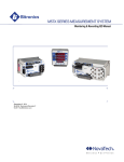
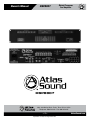
Owner’s Manual
DSP8807
Digital Processor
and Amplifier
DSP8807
1601 Jack McKay Blvd. • Ennis, Texas 75119 U.S.A.
Telephone: 800.876.3333 • Fax: 800.765.3435
– 1 –
Specifications are subject to change without notice.
AtlasSound.com
ier
35
d 35W
ngineered
und
HINA
Digital Processor
and Amplifier
DSP8807
Owner’s Manual
Table of Contents
Important Safety Instructions..........................................................................................................................................2
Introduction ......................................................................................................................................................................4
System Overview Flow Diagram.....................................................................................................................................6
Panel Layout......................................................................................................................................................................8
Installation and Endpoint Termination............................................................................................................................9
Software Installation and Setup....................................................................................................................................14
Specifications .................................................................................................................................................................31
Troubleshooting Guide ..................................................................................................................................................33
Warranty..........................................................................................................................................................................36
Important Safety Instructions
The lightning flash with arrowhead symbol within an
equilateral triangle, is intended to alert the user to the
presence of uninsulated “dangerous voltage “ within the
product’s enclosure that may be of sufficient magnitude
to constitute a risk of electric shock to persons.
CAUTION
RISK OF ELECTRIC SHOCK
DO NOT OPEN
ATTENTION
´
RISQUE DE DECHARGE ELECTRIQUE
-NE PAS OUVRIR.
The exclamation point within an equilateral triangle is
intended to alert the user to the presence of important
operating and maintenance (servicing) instructions in the
literature accompanying the product.
WARNING
TO REDUCE THE RISK OF FIRE OR ELECTRIC SHOCK
DO NOT EXPOSE THIS APPLIANCE TO RAIN OR MOISTURE.
1.
Read these instructions.
2.
Keep these instructions.
3.
Heed all warnings.
4.
Follow all instructions.
5.
Do not use this device near water.
6.
Clean only with dry cloth.
7.
Do not block any ventilation openings. Install in accordance with the manufacturer’s instructions.
8.
Do not install near any heat sources such as radiators, heat registers, stoves, or other devices (including amplifiers) that produce heat.
9.
Do not defeat the safety purpose of the polarized or grounding-type plug. A polarized plug has two blades with one wider than the
other. A grounding type plug has two blades and a third grounding prong. The wide blade or the third prong are provided for your
safety. If the provided plug does not fit into your outlet, consult an electrician for replacement of the obsolete outlet.
10.Protect the power cord from being walked on or pinched particularly at plugs, convenience receptacles, and the point where they
exit from the device.
11.Only use attachments/accessories specified by the manufacturer.
12.Use only with the cart, stand, tripod, bracket, or table specified by the manufacturer, or sold with the device. When a cart is used
use caution when moving the cart/device combination to avoid injury from tip-over.
13.Unplug this device during lightning storms or when unused for long periods of time.
14.Refer all servicing to qualified service personnel. Servicing is required when the device has been damaged in any way, such as
power-supply cord or plug is damaged, liquid has been spilled, or objects have fallen into the device, the device has been exposed
to rain or moisture, does not operate normally, or has been dropped.
15. WARNING: To reduce the risk of fire or electric shock, this device should not be exposed to rain or moisture and objects filled with
liquids, such as a vase, should not be placed on this device.
16.To completely disconnect this equipment from the mains, disconnect the power supply cord plug from the receptacle.
17.The mains plug of the power supply cord shall remain readily operable.
1601 Jack McKay Blvd. • Ennis, Texas 75119 U.S.A.
Telephone: 800.876.3333 • Fax: 800.765.3435
AtlasSound.com
– 2 –
Specifications are subject to change without notice.
Owner’s Manual
DSP8807
Digital Processor
and Amplifier
CAUTION – When Installing the Product
• Plugging in or unplugging the power cord with wet hands may result in electric shock.
•Never move the device with the power cord plugged into the wall, as damage to the power cord may result.
•When unplugging the cord from the wall, grasp the plug, NOT the cord.
•Never install this device in humid or dusty locations, nor in direct sunlight, near sources of heat, or in areas where sooty smoke or
steam are present. Fire and electric shock may result.
•Keep all sides of the device at least 31⁄2" away from objects that may obstruct air flow to prevent the unit's internal temperature rise.
WARNING – When the Device is in Use
•To prevent electric shock, do not remove the device cover as there are high voltage components inside. Refer all servicing to Atlas Sound.
•Should any of the following irregularities occur during use, immediately switch off the power, disconnect the power cord from the
AC outlet and contact Atlas Sound. Do not to attempt to continue operation with the device as this may cause fire or electric shock:
•
Smoke or strange smell coming from the unit.
•
If the device falls or the case is damaged.
•
If water or any metallic objects falls into the device.
• If the power supply cord is damaged in any way.
•
If the device is malfunctioning.
•
Do not insert or drop metallic objects or flammable materials into the ventilation holes of the device's cover,
as this may result in electric shock or fire.
•
Do not place any containers with liquid or metallic objects on the top of the device.
If any liquid spills into the unit, fire or electric shock may result.
•
Never operate this device or touch the power supply cord during an electrical storm, electric shock may result.
•
Never exceed the wattage on the product when connecting equipment. Fire and/or property damage may result.
•
Operate the device only with the voltage specified on the unit. Fire and/or electric shock may result if a higher
voltage is used.
•
Do not modify, kink, or cut the power cord. Do not place the power cord in close proximity to heaters and do not
place heavy objects on the power cord, including the device itself, doing so may result in fire or electrical shock.
•
Ensure that the safety ground terminal is connected to a proper ground. Never connect the ground to a gas pipe
as a catastrophic disaster may result.
• Be sure the installation of the product is stable, avoid slanted surfaces as the product may fall and cause injury or property damage.
CAUTION – When the Device is in Use
•
Never place heavy objects on the product, causing it to fall and/or break, resulting in personal injury and
property damage. In addition, the product itself may fall and cause injury and property damage.
•
Contact Atlas Sound for instructions on cleaning the inside of the unit. Large accumulations of dust inside
the unit may result in heat buildup and fire.
•
Ensure that the power supply plug is securely plugged into the wall outlet. Never allow dust to accumulate
on the power plug or inside the wall outlet.
•
When cleaning the unit or the unit is not to be operated for an extended time period, unplug power cord
from the wall.
1601 Jack McKay Blvd. • Ennis, Texas 75119 U.S.A.
Telephone: 800.876.3333 • Fax: 800.765.3435
– 3 –
Specifications are subject to change without notice.
AtlasSound.com
DSP8807
Digital Processor
and Amplifier
Owner’s Manual
Introduction
The Atlas Sound DSP8807 digital processor “Privacy” system is a self contained, compact multi-zone digital DSP-GUI controlled processor
and digital amplifier capable of simultaneous distribution of masking, paging, and background music signals for usemaybe in Industrial,
Institutional, Commercial and Government facilities.
The Atlas Sound DSP8807 unit is capable of automatic mixing, set up and administration of all 8x8 inputs / outputs per zone (channel)
via an intuitive ‘simple to use’ Graphic User Interface (GUI) managed via a local Windows® based laptop or desktop computer. The
DSP8807 has 8 channels of independent on-board digital class-D amplifiers that are capable of delivering 50W RMS at 70V output.
Additionally a simultaneous audio line level output rated at 1V/600Ω (nominal) per zone is available for driving higher power amplifiers.
The DSP8807 also has two (2) independent uncorrelated pink noise generators which are random and non-repeating up to 215
hours with EQ adjustments programmable on a per zone basis. The DSP8807 provides dynamic control and management based on
IEEE802.1 AVB standards (Audio-Video Bridging) with independent 1⁄3 Octave (28) band EQ *(Filter type is Butterworth @ 19dB and
Linkwitz-Riley at 24dB) and Parametric EQ for calibration of all PA, ambient level sensing and automatic level control on a per zone
basis. Paging (PA) presets can be assigned in 10dB increments (10, 20, 30dB) per zone with automatic gain control (AGC) for all Telco
and microphone paging inputs.
The DSP8807 GUI is called the ‘Sound Media Interface’. The software has the ability to expand up to (256) systems with over 2,000
zones (2,048) with primary and secondary assignment in a zone paging dialing plan. It also provides the ability to set up All zone page,
Group zone page (up to 32 groups) and Single zone page with an architectural dialing plan (2-digit DTMF) set up in the GUI. Each
DSP8807 is capable of managing remote ambient level sensing microphones (ALM-1) for each zone (x8) wired via a single CAT5e cable
up to 1,000 feet from the DSP8807 for automatic adjustment of the masking level based on real-time noise levels with set up and
control via the GUI.
The Atlas Sound DSP8807 system provides the following basic masking capabilities:
• Creates an acceptable level of speech privacy in open work areas
• Enhances speech privacy between modular offices
• Decreases intelligibility and noise distraction caused by stand-up, casual conversations and random room noises
• Reduces awareness of existing sounds
• Increases worker productivity and employee satisfaction
• Enhances clients revenue due to less employee distraction
• Lessens the need for unexpected and expensive acoustical upgrades
• Flexibility which insures specific masking spectrums for varying ceiling types including; t-bar, open, wood slats and clouds
Basic Function
• (8) Channels of Random Pink Noise Generator Non-Repeating Up to 215 Hours
• (8) Audio Outputs of 50W RMS Digital Class-D Amplification at 85% Efficiency
• (8) Audio Line Outputs at 1V/600Ω (Nominal) for Unlimited Power Per Zone
• (8) Independent Outputs of 1⁄3 Octave 28-Band EQ Defined and Shaped in GUI
• IEEE 802.1 AVB (Audio Video Bridging) Technology for Time Aligned Networking of Multiple Units
• AVB Operation Allows IP Based Paging Via Ethernet Connection
• (8) Ambient Sensing Microphone Inputs (RJ45) for Automatic Level Sensing (6dB) and Control
• Compatible with ALM-1 Ambient Sensing Microphones Operating Up to 1,000 Feet Away
• Multiple Audio Source Inputs for Background Music, Paging and Emergency Page Overrides
• Telco Paging Input (Loop Start) with 2 to 5 Digit DTMF (Touch Tone) Dial Plan Defined in GUI
• Multiple ‘Form-C’ Contact Closure Relay Inputs (x4) for Ancillary Devices
• Microphone Input with System Mute
• Emergency Override Inputs for Automatic Page Override
• On-Board MAC Address for IP Addressability and Remote Control Compatible With DHCP MS Server
• User Friendly GUI (Sound Media Interface) for Set Up
1601 Jack McKay Blvd. • Ennis, Texas 75119 U.S.A.
Telephone: 800.876.3333 • Fax: 800.765.3435
AtlasSound.com
– 4 –
Specifications are subject to change without notice.
Owner’s Manual
Digital Processor
and Amplifier
DSP8807
• Zone Expansion from 1 to 2,048 Via Standard CAT5e – CAT6 Cabling (Up to 256 Systems)
• All-Call Page, Group Zone Page, and Single Zone Page Defined in GUI
• Independent Parametric EQ for All Paging Sources
• Microphone Balanced Input with On-Board Phantom Power at 32VDC
• On Board Signal Generators for Paging Confirmation, Busy, and Pre-Announce Tones
• Non-Volatile DSP Memory Components for All System Controls with Ten (10) Year Memory
• DSP8807 Multiple Mounting Options; Rack, Cabinet, Shelf, or Wall at 2RU (3.5") Height x 15" Deep
• Visual Status Front Multicolor LEDs for All Major Inputs and Outputs
• Rear Access Network Connection (RJ45) with Front Manual DSP Reset Button
• Overload, Short, and Current Limit Protection with Automatic Reset for All Critical Components
• All Power Components Are UL Recognized, Boards Are UL94v0 and RoHS
• DSP8807 Is UL / CUL / FCC and CB (International) Listed
BASIC APPLICATIONS DIAGRAM
Client telephone system for
localized or campus wide paging.
Music source for zone
selected playback.
IP switch connecting multiple Atlas
Sound units for AVB (Audio Visual
Bridging) and network access.
Microphone connection for paging
and campus wide
notifications.
IP addressable for over
network system control.
Capable of simultaneously
distributing sound masking, paging,
and music.
Capable of simultaneously
distributing paging and music.
Ambient sensing microphone controlling
sound masking volume in a densely occupied zone.
1601 Jack McKay Blvd. • Ennis, Texas 75119 U.S.A.
Telephone: 800.876.3333 • Fax: 800.765.3435
– 5 –
Specifications are subject to change without notice.
AtlasSound.com
Digital Processor
and Amplifier
DSP8807
Owner’s Manual
SYSTEM OVERVIEW – SIGNAL FLOW DIAGRAM
I/O Processing
Bass-Treble
Line 1
Line 1 CC
Line 2 CC
Bass-Treble
Line 2
Mic CC
EAO CC
Music 1
Music 2
Limiter
Mic
A-D
SMS
Line 1
Lynx
AVIO Core
Signal
Processors
A-D
Line 2
Mic
Network
Page
Telco
A-D
Limiter
Bass-Treble
Para - EQ
Bass-Treble
Para - EQ
Bass-Treble
Para - EQ
Page Matrix
Telco
DTMF
Receiver
Bass-Treble
Music 1
Processor
Restart
Bass-Treble
Music 2
Front
Control
RJ45
Phy
Rear
Control
RJ45
Phy
SMS
Lynx
AVB Core
Network
Processors
Graphic EQ
Noise 1
Filter
Noise 2
Filter
Masking Matrix Array
Graphic EQ
Amb 1
Amb 2
Graphic EQ
Amb 3
SMS
Lynx
Ambient
Mic
Processor
Amb 4
Amb 5
Amb 6
Graphic EQ
Amb 7
Graphic EQ
Amb 8
Graphic EQ
DSP8807 Project
System Functional Diagram
Graphic EQ
Preliminary
March 24th, 2010
Graphic EQ
DSP Block
Rev 1.2
1601 Jack McKay Blvd. • Ennis, Texas 75119 U.S.A.
Telephone: 800.876.3333 • Fax: 800.765.3435
AtlasSound.com
– 6 –
Specifications are subject to change without notice.
Owner’s Manual
Digital Processor
and Amplifier
DSP8807
Amp O/P PCB
EAO
Override
High Pass
High Pass
High Pass
Array
High Pass
High Pass
High Pass
High Pass
High Pass
D-A
Zone Amp 1
D-A
Line Out 1
D-A
Zone Amp 2
D-A
Line Out 2
D-A
Zone Amp 3
D-A
Line Out 3
D-A
Zone Amp 4
D-A
Line Out 4
D-A
Zone Amp 5
D-A
Line Out 5
D-A
Zone Amp 6
D-A
Line Out 6
D-A
Zone Amp 7
D-A
Line Out 7
D-A
Zone Amp 8
D-A
Line Out 8
1601 Jack McKay Blvd. • Ennis, Texas 75119 U.S.A.
Telephone: 800.876.3333 • Fax: 800.765.3435
– 7 –
Specifications are subject to change without notice.
AtlasSound.com
DSP8807
Digital Processor
and Amplifier
Owner’s Manual
DSP8807 FRONT
19.0"
DSP8807 REAR
3.5"
17.1"
DSP8807 TOP PANEL
DSP8807 Top Panel:
Important notifications and
MAC Address screened on top
MAC Address / (2) locations
1601 Jack McKay Blvd. • Ennis, Texas 75119 U.S.A.
Telephone: 800.876.3333 • Fax: 800.765.3435
AtlasSound.com
– 8 –
Specifications are subject to change without notice.
Owner’s Manual
DSP8807
Digital Processor
and Amplifier
INSTALLATION
COMPUTER NETWORK TERMINATION
NOTE: All ‘RJ45’ Network connections must be wired to meet EIA/TIA 568B standard.
256
1601 Jack McKay Blvd. • Ennis, Texas 75119 U.S.A.
Telephone: 800.876.3333 • Fax: 800.765.3435
– 9 –
Specifications are subject to change without notice.
AtlasSound.com
Digital Processor
and Amplifier
DSP8807
Owner’s Manual
70V SPEAKER TERMINATION
Dockable 2-pin/socket connectors (commonly referred to as ‘Phoenix’ type) are used which are keyed or polarized to fit one way – do
not force fit these connectors and follow these basic instructions;
• Do NOT force fit the connectors – they are polarized to fit in one direction
• Follow the +/- wiring polarity to all speakers
• Use only 70V speakers
• Ensure that total speaker wattage taps per channel does NOT EXCEED 80% of the rated output of 50W RMS per zone.
SPEAKER OUTPUTS (70V)
ZONE 1
+
–
ZONE 2
+
–
ZONE 3
+
–
ZONE 4
+
–
50W RMS / ZONE
+
+
–
–
70V SPEAKERS
AUDIO LINE LEVEL TERMINATION (1V/600Ω)
Typical use of the Audio Line Output is to increase the power (Watts) via an auxiliary amplifier capable of powering speakers above the
50W RMS level provided by DSP8807. Ensure the wiring matches the (+ / - / G) for each zone output to each amplifier audio input.
LINE OUTPUTS (1V / 600 OHM)
+
+
–
–
AUXILIARY AMPLIFIER
(ADDED POWER)
1601 Jack McKay Blvd. • Ennis, Texas 75119 U.S.A.
Telephone: 800.876.3333 • Fax: 800.765.3435
AtlasSound.com
– 10 –
Specifications are subject to change without notice.
Owner’s Manual
DSP8807
Digital Processor
and Amplifier
AC POWER INPUT (120VAC @ 60Hz or 240VAC @ 50Hz)
As noted in the ‘important notices’ section the DSP8807 utilizes a UL recognized IEC AC power plug and cord (provided with the unit)
which must not be changed or defeated. Please follow these important instructions. Failure to do so will void the product warranties.
The Mains Plug is the main disconnect device for the product, and shall be located so as to be readily accessible.
NOTE: Once the AC power is switched ‘ON’ it will take approximately ‘30’ seconds to initialize and start up.
•Do not defeat the safety purpose of polarized, keyed or grounding type connectors. A polarized plug has two (or multiple) contacts
with one wider or longer than the other. A grounding type plug has two blades and a third grounding plug. The wide blade or third
prongs are provided for your safety. Do not defeat or change these. If the provided IEC power plug does not fit into your outlet,
consult an electrician or your local authority having jurisdiction to replace the outlet to ensure meeting local building codes while
assuring proper connection.
• Protect the power cord from being walked on or pinched particularly at the plug, receptacle outlet, and the exit point of the unit.
AC POWER IN
Replace AC Fuse with UL
recognized 2A @ 250VAC or
5A @ 110VAC
Typical view of
UL rated Fuse
AC cable with IEC plug provided. All
wiring to meet NEC/ UL code
120VAC
Power
Fuse
120V operation: T 8A L 250V
240V operation: T 5A L 250V
AMBIENT SENSING MICROPHONE (ALM-1) TERMINATION
Typical Ceiling Grid Installation
1601 Jack McKay Blvd. • Ennis, Texas 75119 U.S.A.
Telephone: 800.876.3333 • Fax: 800.765.3435
– 11 –AtlasSound.com
Specifications are subject to change without notice.
DSP8807
Digital Processor
and Amplifier
Owner’s Manual
PAGING MICROPHONE INPUT TERMINATION
BACKGROUND MUSIC AND LINE INPUT TERMINATION
CONTACT CLOSURE SWITCH INPUT TERMINATION
1601 Jack McKay Blvd. • Ennis, Texas 75119 U.S.A.
Telephone: 800.876.3333 • Fax: 800.765.3435
AtlasSound.com
– 12 –
Specifications are subject to change without notice.
Owner’s Manual
DSP8807
Digital Processor
and Amplifier
TELCO PAGING INPUT
CAUTION: Use only with Telephone Equipment that supplies voltages NO GREATER THAN -60VDC, and connects to the
DSP8807 only within a building.
TELCO PAGIN INPUT
LOOP START
TIP
Telephone System with Loop Start trunk and
DTMF keypad (Touch Tone)
RING
DSP8807 has built in tone generators for audible status for paging; connection to the system responds with ‘single beep’, entering a
page plan number responds with ‘two beeps’.
MEMORY BATTERY REPLACEMENT
CAUTION: If battery is incorrectly replaced explosion can occur. Replace only with the same or equivalent type.
BATTERY
(3v 255mAh 23mm)
+
+
Remove metal cover (2 screws) and replace
Battery as needed with 3V, 255 mAh, 23mm x
3mm size. Typical is Lithium cell coin battery,
Panasonic model CR2330
3v
Typical view of
3v cell coin battery
MOUNTING
The DSP8807 unit is designed to mount into standard EIA cabinets, free standing racks, or consoles using the (x4) front slots. NOTE:
Allow a minimum one (1) rack space above and below (at 3.5") between the DSP8807 and any other electronic equipment to ensure
proper thermal ventilation. This unit may also be mounted on a shelf using the pads provided (x4).
SYSTEM OVERVIEW – SYSTEM HARDWARE / SOFTWARE REQUIREMENTS
The DSP8807 unit has the following hardware and software computer requirements;
• Microsoft Windows Operating system shall be: XP Professional, Windows Vista, Windows 7 or better
• 50MB of available hard disk space
• 512MB of RAM of higher
• A network connection with a minimum data transfer rate of 10Mbps or higher (100Mbps is recommended).
1601 Jack McKay Blvd. • Ennis, Texas 75119 U.S.A.
Telephone: 800.876.3333 • Fax: 800.765.3435
– 13 –AtlasSound.com
Specifications are subject to change without notice.
DSP8807
Digital Processor
and Amplifier
Owner’s Manual
Installation – GUI / “Sound Media Interface” Set Up
START UP – “SETTINGS”
1.The DSP8807 is based on Microsoft ethernet router with DHCP server. Each unit has a specific MAC address embedded in the
system (shown on the rear panel and top plate of the unit).
2.The DSP8807 GUI – Sound Media Interface operating software requires a PC based computer running Microsoft® Windows® XP
Professional or higher. The DSP8807 system will operate with: Windows® XP Pro, Windows® XP Media Center, Windows® XP
Pro x64, Windows® Vista (Business, Enterprise, Ultimate), Windows® 7, Windows® Server 2003, Windows® Server 2008, and
Windows® Server 2008 R2.
3.The unit being installed will show the main program window (below), select ‘Settings’ and then “Poll for Hardware” which applies
the IP address. The IP address will appear in the window, select “Connect to this unit”.
1601 Jack McKay Blvd. • Ennis, Texas 75119 U.S.A.
Telephone: 800.876.3333 • Fax: 800.765.3435
AtlasSound.com
– 14 –
Specifications are subject to change without notice.
Owner’s Manual
DSP8807
Digital Processor
and Amplifier
START UP – ‘SYSTEM’
1.Select ‘System’ from the menu bar (upper left side of screen). All DSP8807 programmable options are then visible in the main
‘System Diagram’ dialog box (center of screen). All options, when selected, will display a second dialog box for specific settings
that will appear in the lower section. As you work in this screen it will display ‘Active View’ at the top. On the right side of the
screen there will be “scroll bars” that may be used (up/down) to reach all settings for zones 1 to 8.
2.There are several methods of making adjustments to the system as shown below. When the cursor (mouse) is moved across the
screen, the “active” item will light up.
Methods of adjustments include:
• Move slider up / down
• Click on up / down symbol
• Type in number
1601 Jack McKay Blvd. • Ennis, Texas 75119 U.S.A.
Telephone: 800.876.3333 • Fax: 800.765.3435
– 15 –AtlasSound.com
Specifications are subject to change without notice.
DSP8807
Digital Processor
and Amplifier
Owner’s Manual
3. The ‘Sound Media Interface’ GUI will automatically prompt you to enter acceptable values within the operating system when these
are being typed in.
NOTE: When entering an adjustment
value and a value outside the operating
range is entered, an "Out of Range"
message will appear prompting for the
a new value to be entered.
MASKING - NOISE SETTINGS
These are all settings relative to establishing appropriate masking levels for each Zone 1 to 8. Start adjustment with the LEFT selection
buttons; Noise 1 and 2 and work in progression to the right to ‘Noise Trim’. The DSP8807 has two (2) independent random masking
generators on board that can be optioned in any given zone.
NOISE 1 AND 2:
1. This button selection turns the masking, On or Off.
NOISE 1 AND 2 VOLUME
1.Select the ‘Noise 1 Volume / Noise 2 Volume’ which presents a ‘Noise 1 Volume’ level adjustment which can be set by sliding
the center knob or typing in the desired level from -65dB to +15dB.
1601 Jack McKay Blvd. • Ennis, Texas 75119 U.S.A.
Telephone: 800.876.3333 • Fax: 800.765.3435
AtlasSound.com
– 16 –
Specifications are subject to change without notice.
Owner’s Manual
DSP8807
Digital Processor
and Amplifier
2.Select the ‘Noise Matrix’ for Noise 1 or 2 which drops down the ‘Noise 1 Matrix’ option box, select Noise 1 or Noise 2 for each
zone 1 to 8.
NOISE ‘GEQ’ (GRAPHIC EQ)
3.Select the Noise ‘GEQ’ (Graphic EQ) button for each zone which drops down the 1⁄3 Octave 28 band EQ with settings from 40Hz
to 20kHz. Set the desired frequency by moving the slider or typing the number at the bottom with a frequency scale from -15dB to
+15dB. NOTE: The specific band being set will light up as you scroll across.
1601 Jack McKay Blvd. • Ennis, Texas 75119 U.S.A.
Telephone: 800.876.3333 • Fax: 800.765.3435
– 17 –AtlasSound.com
Specifications are subject to change without notice.
DSP8807
Digital Processor
and Amplifier
Owner’s Manual
NOISE TRIM/ dB LEVEL
4.In the ‘System’ select mode with ‘Active View’ open; select ‘NOISE TRIM’ button which presents an option for raising or
lowering the level on a per-zone basis as shown below. Each increment (54dB to 72dB) represents a 1dB increase or decrease
from the base setting. Select required level button(s) from 54dB to 72dB in the box which activates 1dB ‘trip point’ – repeat
settings for zones 1 through 8.
Setting example: If you select 57dB, 63dB and 69dB the masking noise level will raise 1dB as each ambient level is
reached this will occur as each level is passed for a total of 3dB masking noise increase as the ambient level passes
69dB. The reverse will occur as the ambient level decreases past the selected ‘trip points’ so that the masking noise
level returns to the base level setting.
SOURCE INPUTS: LINE (1, 2), MUSIC, MIC, NETWORK, TELCO
1601 Jack McKay Blvd. • Ennis, Texas 75119 U.S.A.
Telephone: 800.876.3333 • Fax: 800.765.3435
AtlasSound.com
– 18 –
Specifications are subject to change without notice.
Owner’s Manual
DSP8807
Digital Processor
and Amplifier
LINE 1 AND LINE 2 INPUTS: TONE
1.The DSP8807 allows multiple source inputs which have numerous adjustment options. Starting with the Line 1 and Line 2
input (top left side) you can adjust both ‘Tone’ and ‘Volume’. Selecting ‘Line 1’ and ‘Tone’ will drop down a box ‘Line 1 Tone’
with Bass and Treble adjustments; Base: Frequency: 100Hz-1000Hz and Level: -15dB to +15dB. Move the slider or type in
the required number.
LINE 1 AND LINE 2 INPUTS: VOLUME
1.After selection Line 1 or Line 2, select the ‘VOL’ (Volume) button which drops down a ‘Line 1 Volume’ box with a slide adjustment
from -65dB to +15dB. In order to test volume you can select ‘Start Meter’ which provides an active meter view of music ‘signal
present’. When the test is complete select ‘Stop Meter’.
1601 Jack McKay Blvd. • Ennis, Texas 75119 U.S.A.
Telephone: 800.876.3333 • Fax: 800.765.3435
– 19 –AtlasSound.com
Specifications are subject to change without notice.
DSP8807
Digital Processor
and Amplifier
Owner’s Manual
MUSIC INPUT: TONE
1.Music has both ‘TONE’ and ‘VOL’ (volume) adjustments. Select Music ‘TONE’ button which drops down a ‘Music Tone’ box with
adjustment for Bass and Treble. The adjustable ranges for the bass include: frequency, 100Hz-1000Hz, and Level, -15dB to +15dB.
Move the slider or type in the desired number.
MUSIC INPUT: VOLUME
1.After selection Music, select ‘VOL’ (volume) button. This will drop down a ‘Music Volume’ box with a slide adjustment from -65dB
to +15dB. In order to test volume you can select ‘Start Meter’ which provides an active meter view of music ‘signal present’.
When test is complete select ‘Stop Meter’.
1601 Jack McKay Blvd. • Ennis, Texas 75119 U.S.A.
Telephone: 800.876.3333 • Fax: 800.765.3435
AtlasSound.com
– 20 –
Specifications are subject to change without notice.
Owner’s Manual
DSP8807
Digital Processor
and Amplifier
MICROPHONE INPUT: COMPRESSOR
1.Select ‘MIC’ (Microphone) and then ‘COMPRESS’ (Compressor) to activate compression of audio signal with adjustment to
‘Threshold’ and ‘Ratio’ as follows, threshold has a range from -54dB to +6dB and ratio is from 1-10. Move the slider or type in the
required number.
MICROPHONE INPUT: TONE
1.Select Microphone ‘TONE’ button. This will drop down a ‘MIC Tone’ box with adjustment for Bass and Treble. The adjustable
ranges include: (Bass) frequency, 100Hz-1000Hz, and level, -15dB to +15dB, (Treble) frequency, 1000Hz to 20,000Hz, and level,
-15dB to +15dB. Move the slider or type in the required number. NOTE: Each adjustment will light up when cursor is working in a
specific area.
1601 Jack McKay Blvd. • Ennis, Texas 75119 U.S.A.
Telephone: 800.876.3333 • Fax: 800.765.3435
– 21 –AtlasSound.com
Specifications are subject to change without notice.
DSP8807
Digital Processor
and Amplifier
Owner’s Manual
MICROPHONE INPUT: ‘PEQ’ / PARAMETRIC EQ
1.Select the MIC Parametric ‘PEQ’ to adjust Level, Q and frequency. Select each function and adjust to these ranges; level is -14dB
to +14dB, ‘Q’ is 1 to 5 and frequency is 50Hz to 16kHz.
MICROPHONE INPUT: VOLUME
1.After selection MIC select ‘VOL’- Music (volume) button. This will drop down a ‘Mic Volume’ box with a slide adjustment from
-65dB to +15dB. In order to test volume you can select ‘Start Meter’ which provides an active meter view of music ‘signal present’.
When the test is complete select ‘Stop Meter’.
1601 Jack McKay Blvd. • Ennis, Texas 75119 U.S.A.
Telephone: 800.876.3333 • Fax: 800.765.3435
AtlasSound.com
– 22 –
Specifications are subject to change without notice.
Owner’s Manual
DSP8807
Digital Processor
and Amplifier
NETWORK INPUT: TONE
1.Select Network ‘TONE’ button. This will drop down a ‘Network Tone’ box with adjustment for Bass and Treble as follows: (Bass)
frequency; 100Hz-1000Hz, level, -15dB to +15dB, (Treble) frequency, 1000Hz to 20,000Hz, and level, -15dB to +15dB. Move the
slider, hit up/down symbol or type in the required number. NOTE: Each adjustment will light up when cursor is working in a specific
area.
NETWORK INPUT: ‘PEQ’ / PARAMETRIC EQ
1.Select the MIC Parametric ‘PEQ’ button to adjust Level, Q and frequency. Select each function and adjust to these ranges; level is
-14dB to +14dB, ‘Q’ is 1 to 5 and frequency is 50Hz to 16kHz.
1601 Jack McKay Blvd. • Ennis, Texas 75119 U.S.A.
Telephone: 800.876.3333 • Fax: 800.765.3435
– 23 –AtlasSound.com
Specifications are subject to change without notice.
DSP8807
Digital Processor
and Amplifier
Owner’s Manual
NETWORK INPUT: NETWORK VOLUME
1.After selecting NETWORK button, select ‘VOL’ (volume) button. This will drop down a ‘Network Output Volume’ box with a slide
adjustment from -65dB to +15dB. In order to test volume you can select ‘Start Meter’ which provides a active meter view of music
‘signal present’. When the test is complete select ‘Stop Meter’.
TELCO INPUT: COMPRESSOR
1.Select ‘TELCO’ input button (Telephone) and then ‘COMPRESS’ (Compressor) to activate compression of audio signal with
adjustment to ‘Threshold’ and ‘Ratio’ as follows. Threshold has a range from -54dB to +6dB and Ratio is from 1-10. Move the
slider, hit up / down symbol or type in the required number.
1601 Jack McKay Blvd. • Ennis, Texas 75119 U.S.A.
Telephone: 800.876.3333 • Fax: 800.765.3435
AtlasSound.com
– 24 –
Specifications are subject to change without notice.
Owner’s Manual
DSP8807
Digital Processor
and Amplifier
TELCO INPUT: TONE
1.Select Telco ‘Tone’ button. This will drop down a ‘Telco Tone’ box with adjustment for Bass and Treble as follows: (Base) frequency,
100Hz-1000Hz, level, -15dB to +15dB, (Treble) frequency, 1000Hz to 20,000Hz, and level, -15dB to +15dB. Move the slider, hit up/
down symbol or type in the required number. NOTE: Each adjustment will light up when cursor is working in a specific area.
TELCO INPUT: TELCO ‘PEQ’ / PARAMETRIC EQ
1.Select the MIC Parametric EQ to adjust Level, Q and frequency. Select each function and adjust to these ranges, level is -14dB to
+14dB, ‘Q’ is 1 to 5, and frequency is 50Hz to 16kHz.
1601 Jack McKay Blvd. • Ennis, Texas 75119 U.S.A.
Telephone: 800.876.3333 • Fax: 800.765.3435
– 25 –AtlasSound.com
Specifications are subject to change without notice.
DSP8807
Digital Processor
and Amplifier
Owner’s Manual
TELCO INPUT: VOLUME
1.Select TELCO ‘VOL’- (volume) button. This will drop down a ‘Telco Volume’ box with a slide adjustment from -65dB to +15dB.
Move the slider, hit up/down symbol or type in the required number. NOTE: Each adjustment will light up when cursor is working in
a specific area. In order to test volume you can select ‘Start Meter’ which provides an active meter view of music ‘signal present’.
When the test is complete select ‘Stop Meter’.
TELCO INPUT: TELCO TONE VOLUME
2.Select ‘To Telco Tone’. This will drop down ‘Telco Tones Volume’ box which can be set from -15dB to +15dB. Move the slider, hit
up/down symbol or type in the required number. In order to test the volume select ‘Start Meter’ this provides an active meter view
of music ‘signal present’. When the test is complete select ‘Stop Meter’.
1601 Jack McKay Blvd. • Ennis, Texas 75119 U.S.A.
Telephone: 800.876.3333 • Fax: 800.765.3435
AtlasSound.com
– 26 –
Specifications are subject to change without notice.
Owner’s Manual
DSP8807
Digital Processor
and Amplifier
PAGE MATRIX
1.Select ‘PAGE MATRIX’ button to manually route an input page signal to its associated zone output (1-8). This can be used to check
sound level and quality of the various page input sources (Telco, Mic, Line, Network) without having to create a page plan or
execution of that plan. Select the ‘Page Matrix’ button and the desired page input source, then select the ‘Zone Mix’ button to set
the input levels for each zone in the test. When desired levels are set, select the ‘DSP Run Mode’ button which enables system
processors to automatically set levels when page is made.
1601 Jack McKay Blvd. • Ennis, Texas 75119 U.S.A.
Telephone: 800.876.3333 • Fax: 800.765.3435
– 27 –AtlasSound.com
Specifications are subject to change without notice.
DSP8807
Digital Processor
and Amplifier
Owner’s Manual
ZONE MIX AND VOLUME
ZONE MIX:
1. Select ‘ZONE MIX’ button to adjust relative levels for Page, Noise, Music from -65dB to +15dB. Repeat for all zone outputs Zone 1 to 8.
ZONE VOLUME:
1.Select ‘VOL’ (volume) button for ‘Zone Out 1’ (to Zone Out 8) which drops down a ‘Zone Out 1 Volume’ box with a slide adjustment
from -65dB to +15dB.
1601 Jack McKay Blvd. • Ennis, Texas 75119 U.S.A.
Telephone: 800.876.3333 • Fax: 800.765.3435
AtlasSound.com
– 28 –
Specifications are subject to change without notice.
Owner’s Manual
DSP8807
Digital Processor
and Amplifier
PAGE PLANS
1.In setting up the DSP8807 ‘Page Plan’ select the ‘PAGE PLANS’ button. This will drop down the ‘Page Plans’ box. Select which
‘Local Zones’ 1 through 8 (specific to each DSP8807 unit being programmed) are to receive Telco, Mic/Line 1, or Line 2 source
inputs to be broadcast into these zones. Repeat this step relative to the ‘Network Zones’ to be sent these broadcast pages or
sources. The Telco ‘Page Plan’ zones are 2-digit DTMF codes ranging from ‘00’ to ‘99’. The ’Page Plan’ consists of 100 Telco dial
plans from 00 to 99 and one (1) for Line1 and Line2 and Microphone. NOTE: The switch ‘dry’ contact closures or the rear panel are
used to select the Line 1, Line 2 and Mic page plans.
2. Each Page Plan has ‘Local’ and ‘Network‘ zones. Page input sources will route to those which are selected.
For multiple DSP8807 units; when any unit, executes a page it will broadcast to all other units connected on the network. The ‘Network
Zone’ button within the ‘Page Plan’ when selected will route the page output to the selected ‘Network Zone’ outputs
EXAMPLE: There are two units networked together, one on each floor of an office building with (8) zones per floor. There is a
requirement for an ‘All Page’ to (16) zones from the ‘Mic’ input. To do this you set the ‘Mic Page’ plan to output to all local zones and
all network zones.
1601 Jack McKay Blvd. • Ennis, Texas 75119 U.S.A.
Telephone: 800.876.3333 • Fax: 800.765.3435
– 29 –AtlasSound.com
Specifications are subject to change without notice.
DSP8807
Digital Processor
and Amplifier
Owner’s Manual
DSP RUN MODE
1. Select ‘DSP RUN MODE’ when you need to reset and test all DSP processors.
MONITOR AMBIENT MICS (MICROPHONES / ALM-1)
1.When ALM-1 remote ambient microphones are connected to the DSP8807, the ‘MONITOR AMBIENT MICS’ button can be
selected to view status of microphone operation as a ‘signal present’ voltage (milliamps) to indicate DSP8807 is receiving input
signal. There are two independent meters: Left meter reads every (2) seconds averaged over one (1) minute the Right meter is the
real time dB level based on settings made in the ‘Noise Trim’ option.
1601 Jack McKay Blvd. • Ennis, Texas 75119 U.S.A.
Telephone: 800.876.3333 • Fax: 800.765.3435
AtlasSound.com
– 30 –
Specifications are subject to change without notice.
Owner’s Manual
DSP8807
Digital Processor
and Amplifier
SPECIFICATIONS
SYSTEM PERFORMANCE / DSP PROCESSORS
Dynamic Range
>102dB A-Weighted
Frequency Response
80Hz – 20kHz ± 3dB at Rated Output
Distortion THD+N
.001% Typical at +4dBu, 1kHz, 0dB Gain
Input Sensitivity
≤ 1.0% at 1kHz at Rated Output
Interchannel Crosstalk
> 80dB Typical
Crosstalk Input to Output
> 80dB
Channel Separation
> 100dB at 1kHz (In Thru Out)
ommon Mode Rejection
C
Ration (CMRR)
> 50dB, 80Hz – 20kHz Typical > 55dB at 1kHz
Processor Capacity
264 MIPS, 528MFLOPS, Continuous Operation
Sample Rate Audio Conversion48kHz
D/A Converter Type (Audio)
24-bit Sigma Delta
D/A Performance Dynamic
Range (Converter) > 100dB A-Weighted
A/D Performance Dynamic Range
> 110dB A-Weighted
Non-Volatile MemoryMemory Storage for All Programs and Set Up Protected for (24) Hours in Power Brown Out,
Interruption or Computer Shut Down. Data Settings Good for (10) Years W/O Refresh
DSP Manual Restart
Front Restart Manual Button to Reload DSP’s
CODEC – DSP Protection
All I/O Protected with Buffers from Spikes and Transients or Sneak Currents
SYSTEM INPUTS (unless noted located on rear panel)
Power AC Mains
IEC 3-pin with Ground, 100-240VAC, 50-60HZ with ON/OFF Manual Switch with Replaceable Fuse
Network – Data
RJ45 Module Jack (EIA 568B)
Telco Loop Start
2-pin Dockable Keyed Connector
Input Transformer
600Ω
Ring Voltage
105V – 14V (POTS – VoIP)
DTMF Dial Plan
Single, Group or All Page
Microphone 3-pin Dockable Keyed Connector
Background Music RCA Connector 10K Ohm (Sum to Mono)
Master Override
2-pin Dockable Keyed Connector (1V – 70V nominal)
Emergency Audio Off (EAO)
2-pin Dockable Keyed Connector, ‘NO’ Normally Open Contact Closure
Ambient Sensing Microphones (x8)
RJ45 Modular Jack (EIA 568B) No Polarity
1601 Jack McKay Blvd. • Ennis, Texas 75119 U.S.A.
Telephone: 800.876.3333 • Fax: 800.765.3435
– 31 –AtlasSound.com
Specifications are subject to change without notice.
Digital Processor
and Amplifier
DSP8807
Owner’s Manual
SYSTEM OUTPUTS (unless noted located on rear panel)
Speakers (x8)
2-pin Dockable Keyed Connector (70v at 50WRMS)
Audio Line Level (x8)
3-pin Dockable Keyed Connector (1v Nominal)
Microphone Frequency Level
80Hz – 18kHz
Music 80Hz – 20kHz
Line Out
80Hz – 18kHz
Telco
250Hz – 4kHz
Network System Link RJ45 Modular Jack (EIA 568B)
Ancillary Line Out (x2)
2-pin Dockable Keyed Connector, Contact Closure
SYSTEM AMPLIFIERS (x8)
Frequency Response
80Hz – 20kHz, ± .25dB
Total Distortion
.001% typical at +4dB, 1kHz, 0dB Gain
Transformer Output
70,7V and IV Line Level
Efficiency
85% or Better
Gain Control
Adjustable to 34dB
Power Supply
UL / CUL /CE Recognized
Input Impedance50kΩ
Output Impedance8Ω
Carrier Frequency400kHz
Peak Current1.2A
MTBF (Mean Time Between Failure)
100,000 Hours
EMC / EMI Radiation
FCC Part 15 Class B, EN6100, CISPR 22
SYSTEM MECHANICAL DATA
Dimensions (L x W x H)
14.0" (358mm) x 19.0" (482.6mm) x 3.5" (88.9mm)
Material (Outer Housing)
CRS (Cold Roll Steel) 18AWG (.047" Nominal)
Finish
Flat Black Powder Coat with Zinc Undercoat Corrosion Resistant
Printed Circuit Boards
UL recognized UL94VO
Electronic Components
RoHS
Operating Temperature
0˚ to +50˚C
Storage Temperature
-40˚ to + 85˚C
Humidity
95% Non-Condensing (Max.)
1601 Jack McKay Blvd. • Ennis, Texas 75119 U.S.A.
Telephone: 800.876.3333 • Fax: 800.765.3435
AtlasSound.com
– 32 –
Specifications are subject to change without notice.
Owner’s Manual
DSP8807
Digital Processor
and Amplifier
TROUBLESHOOTING GUIDE
1. Read and review all sections and follow instructions in this manual.
2.Before terminating speakers to ‘Speaker Output (70V)’ Zone 1 to 8, verify that all wiring is free from shorts, opens, crosses, ground
problems or loose or frayed wiring. Ensure wiring follows the correct polarity (+ / -).
3.Ensure AC power is correctly terminated with the IEC power cord provided. If after power is activated and system input and output
terminations are verified and no audio is detected, ensure all volume and activation settings have been properly set and applied in the
operating GUI/Sound Media Interface per instructions. Ensure that all speakers are connected to the DSP8807.
4.If you continue to experience difficulty please contact Atlas Sound Customer Service department by telephone at 1-800-876-333,
online at www.AtlasSound.com, or by email at [email protected].
1601 Jack McKay Blvd. • Ennis, Texas 75119 U.S.A.
Telephone: 800.876.3333 • Fax: 800.765.3435
– 33 –AtlasSound.com
Specifications are subject to change without notice.
DSP8807
Digital Processor
and Amplifier
Owner’s Manual
Notes
1601 Jack McKay Blvd. • Ennis, Texas 75119 U.S.A.
Telephone: 800.876.3333 • Fax: 800.765.3435
AtlasSound.com
– 34 –
Specifications are subject to change without notice.
Owner’s Manual
DSP8807
Digital Processor
and Amplifier
Notes
1601 Jack McKay Blvd. • Ennis, Texas 75119 U.S.A.
Telephone: 800.876.3333 • Fax: 800.765.3435
– 35 –AtlasSound.com
Specifications are subject to change without notice.
DSP8807
Digital Processor
and Amplifier
Owner’s Manual
Limited Warranty
All products manufactured by Atlas Sound are warranted to the original dealer/installer, industrial or commercial purchaser to be free
from defects in material and workmanship and to be in compliance with our published specifications, if any. This warranty shall extend
from the date of purchase for a period of three years on all Atlas Sound products, including SOUNDOLIER brand, and ATLAS SOUND
brand products except as follows: one year on electronics and control systems; one year on replacement parts; and one year on
Musician Series stands and related accessories. Additionally, fuses and lamps carry no warranty. Atlas Sound will solely at its discretion,
replace at no charge or repair free of charge defective parts or products when the product has been applied and used in accordance
with our published operation and installation instructions. We will not be responsible for defects caused by improper storage, misuse
(including failure to provide reasonable and necessary maintenance), accident, abnormal atmospheres, water immersion, lightning
discharge, or malfunctions when products have been modified or operated in excess of rated power, altered, serviced or installed
in other than a workman like manner. The original sales invoice should be retained as evidence of purchase under the terms of this
warranty. All warranty returns must comply with our returns policy set forth below. When products returned to Atlas Sound do not
qualify for repair or replacement under our warranty, repairs may be performed at prevailing costs for material and labor unless there is
included with the returned product(s) a written request for an estimate of repair costs before any nonwarranty work is performed. In
the event of replacement or upon completion of repairs, return shipment will be made with the transportation charges collect.
EXCEPT TO THE EXTENT THAT APPLICABLE LAW PREVENTS THE LIMITATION OF CONSEQUENTIAL DAMAGES FOR
PERSONAL INJURY, ATLAS SOUND SHALL NOT BE LIABLE IN TORT OR CONTRACT FOR ANY DIRECT, CONSEQUENTIAL
OR INCIDENTAL LOSS OR DAMAGE ARISING OUT OF THE INSTALLATION, USE OR INABILITY TO USE THE PRODUCTS.
THE ABOVE WARRANTY IS IN LIEU OF ALL OTHER WARRANTIES INCLUDING BUT NOT LIMITED TO WARRANTIES OF
MERCHANTABILITY AND FITNESS FOR A PARTICULAR PURPOSE.
Atlas Sound does not assume, or does it authorize any other person to assume or extend on its behalf, any other warranty, obligation,
or liability. This warranty gives you specific legal rights and you may have other rights which vary from state to state.
Should your DSP8807 require service, please contact the Atlas Sound warranty department at
1-608-325-8717, to obtain an RA number.
Atlas Sound Tech Support can be reached at 1-800-876-3333.
Visit our website at www.AtlasSound.com to see other Atlas products.
©2012 Atlas Sound L.P. All rights reserved. Atlas Sound and Atlas Learn are trademarks of Atlas Sound L.P.
All other trademarks are the property of their respective owners. ATS004274 RevA 3/12
1601 Jack McKay Blvd. • Ennis, Texas 75119 U.S.A.
Telephone: 800.876.3333 • Fax: 800.765.3435
AtlasSound.com
– 36 –
Specifications are subject to change without notice.