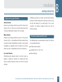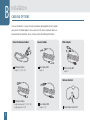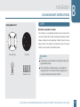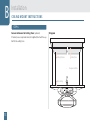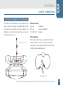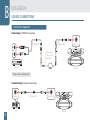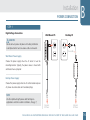
1
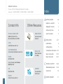
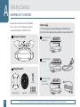
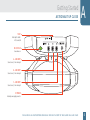
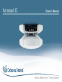
Astronaut CL
Owner's Manual
Technical Audio for the 21st Century Classroom
OWNER'S MANUAL
For use with the following Astronaut CL systems.
Index
System No.: ASTRO-CLW001 | ASTRO-CLD001 | ASTRO-CLR001
A GETTING STARTED
Contact Info
Online Resources
CETACEA SOUND CORP
NEWS CENTER
2003 East Center Circle
Plymouth, Minnesota 55441
Announcements
& Events
SALES
[email protected]
CUSTOMER SERVICE
[email protected]
PHONE
@
2–5
Important — Read First
2
Shipping Kit Contents
3
Astronaut Up Close
4
Safety Precautions
5
B INSTALLATION
6–17
Installer Notes
6
Cabling Options
7
EMAIL / RSS
Ceiling Mount Instructions 8–13
News Delivered
Your Way
Source Connections
14–15
Power Connection
16–17
C TECHNICAL SUPPORT
18–20
(763) 559-1019
U.S.A., Canada, and Caribbean
(800) 556-1922
SUPPORT
(763) 559-1585
Documentation
& Resources
ONLINE
1
Troubleshooting Guide
FAX
www.cetaceasound.com
Contact Info
D LIMITED WARRANTY
18–19
20
21
Getting Started
IMPORTANT— READ FIRST
The Astronaut is an amplified speaker
Astronaut branded speaker systems are amplified and designed
to plug into either mono or stereo sources of sound. Please check
the model number of your speaker for input specifications.
Common Sources
Computer
Projector
Microphone
DVD / VHS
A
Turn OFF special effects
When using an electronic source, turn off all equalizer or
compression algorithm effects, commonly called “bass boost”,
“surround sound”, “jazz”, etc. If connecting to a computer,
make sure that the sound card software is properly set up
for uncompressed and un-boosted stereo output. Use only
the stereo output from DVD’s and personal computers. The
Astronaut is not designed to plug into third party amplifiers,
pre-amps, or subwoofer output jacks. Most line and variable
headphone jacks are suitable sources.
Interactive Whiteboard
CD / iPod® / iPad®
The Astronaut has a built-in amplifier. Connect to fixed or
variable line level sources only.
iPod® and iPad® are registered trademarks of Apple Inc.
PLEASE READ ALL INSTRUCTIONS CAREFULLY AND KEEP A COPY OF THIS GUIDE IN A SAFE PLACE
2
A
Getting Started
SHIPPING KIT CONTENTS
Please check that you have all of the following
items. If any items are missing, please contact
Cetacea Sound directly at (800) 556-1922.
Astronaut CL Speaker
Power Supply
1 of the following 3 power supply (PS) packages is included with your
system. Refer to the original order documentation for system number (S/N).
S/N: ASTRO-CLW001
Wall Mount PS
S/N: ASTRO-CLD001
Desktop PS
Ceiling Mount Kit
S/N: ASTRO-CLR001
Eye Bolt
Mounting Bracket
3
Ceiling Plate
Wall Mount PS
w/ 30' Ext. Cable
Aluminum Bolts (4)
PLEASE SAVE THE BOXES IN CASE YOU NEED TO RETURN YOUR PRODUCT FOR ANY REASON
Getting Started
ASTRONAUT UP CLOSE
A
TWIST
Twist right to install /
left to uninstall
ON / OFF LED
Green when on
A – LINE INPUT
Stereo/mono, 3.5 mm mini-jack
B – LINE INPUT
Stereo/mono, 3.5 mm mini-jack
C – LINE INPUT
Stereo/mono, 3.5 mm mini-jack
DC POWER
External power supply connector
PLEASE READ ALL INSTRUCTIONS CAREFULLY AND KEEP A COPY OF THIS GUIDE IN A SAFE PLACE
4
A
Getting Started
SAFETY PRECAUTIONS
Follow these instructions & use precautions
Safeguard this equipment from high humidity conditions.
Read the instructions completely prior to attaching the
speaker overhead.
Take special care to not drop the equipment while
mounting to the ceiling.
Heed to all cautions and warnings posted within this guide
and on the speaker equipment.
When not using the equipment for long periods of time,
e.g. one month or longer, disconnect the power supply. The
Astronaut has over-voltage and diode protection built in;
however, it is best to err on the side of caution.
NOTE
All literature can be found on our website. Please download
an electronic copy of this guide for your records.
5
Never force anything into the openings or source inputs of
the speaker equipment.
Do not use this equipment if it shows obvious signs of
damage from shipping or dropping.
Do not use this equipment if ambient temperatures exceed
120 °F (48 °C).
Make sure equipment is properly mounted according to the
Ceiling Mount Instructions found in this guide. This is the
only approved method of installation; any other may cause
a loss in warranty.
Installation
INSTALLER NOTES
Input source specifications
Stereo Sources
Maximum input voltage should not exceed 300 mV per input
channel (A, B, or C). Do not use any multi-channel sources like
3-channel, Dolby Digital 5-channel, THX, or Q-Sound.
Mono Sources
Maximum input voltage should not exceed 150 mV per input
channel (A, B, or C). Use microphones that offer a mono or stereo
line output instead of microphone level output. Cetacea Sound
microphones are compatible with the Astronaut. Use of other
brands may result in unpredictable results and is not advised.
Line Level Sources
Although preamps, projector outputs, and music mixers are
popular, it is possible to “overdrive” the Astronaut with these
devices, leading to premature failure and a loss of warranty
coverage.
B
Additionally, equalizers, bass boost, surround sound, QSound,
spatializer, and other compression techniques are not necessary
and will add nothing to the sound quality. This can also
“overdrive” the Astronaut, leading to failure and a loss of
warranty coverage.
Recommended assembly tools
The following tools are recommended to mount the Astronaut
to a suspended ceiling tile.
Phillips head screwdriver
Hand drill with ¼" and ½" bits
Measuring tape
PLEASE READ ALL INSTRUCTIONS CAREFULLY AND KEEP A COPY OF THIS GUIDE IN A SAFE PLACE
6
B
Installation
CABLING OPTIONS
Cetacea Sound offers a variety of source and power cabling options to best support
your specific installation project. Please ensure that all source and power cables are
procured prior to installation. Please visit our website for ordering information.
Power Extension Cables
Source Cables
RCA Adapter
AC Extension Cables
Mono Cables, M-M
RCA to 3.5 mm, M-F
Lengths: 6' | 10' | 20' | 30'
Length: 6'
Length: 6'
Volume Control
DC Extension Cables
Lengths (non-plenum): 6' | 10' | 20' | 40'
Lengths (plenum): 20' | 40'
7
Stereo Cables, M-M
Lengths: 3' | 20'
In-line Volume Control, M-F
Installation
CEILING MOUNT INSTRUCTIONS
B
STEP 1
Ceiling Mount Kit
Determine Speaker Location
The Astronaut is very forgiving and does not need to be in the
center of the room for the best sound quality. Typically, installers
choose a location near the projector in order to share the same
power source in the ceiling. Try to maintain at least 4' of space
from the nearest wall or vertical obstruction.
Mounting Bracket
Ceiling Plate
CAUTION
Install speaker away from direct heat, high humidity, and
physical obstructions.
Eye Bolt
Aluminum Bolts (4)
Do not install the Astronaut speaker near a projector
exhaust port or fan. The hot air from the projector can
cause the Astronaut to overheat and fail.
PLEASE READ ALL INSTRUCTIONS CAREFULLY AND KEEP A COPY OF THIS GUIDE IN A SAFE PLACE
8
B
Installation
CEILING MOUNT INSTRUCTIONS
STEP 2
Tap Holes Into Ceiling Tile
Remove a ceiling tile and set it on a firm surface. Use the ceiling
plate as a guide to mark all 5 holes at locations A and B.
Diagrams
A
Drill or tap ¼" holes at location A for the provided 4 aluminum
bolts. Drill or tap a ½" hole at location B in the ceiling surface
for the security eye bolt.
Above Ceiling Cabling (optional)
If cables will be routed above the ceiling, cut a 1" hole into the
ceiling tile approximately 6" away from where the front of the
speaker will be.
9
6 in.
B
A
Installation
CEILING MOUNT INSTRUCTIONS
B
STEP 3
Mount Ceiling Plate and Bracket
Using the provided 4 aluminum bolts, fasten the ceiling plate C
to the top of the ceiling tile and ceiling bracket D to the bottom
of the ceiling tile. The bolts should be secured snugly; do not
over-tighten.
Diagrams
C
D
For Solid Ceiling Surfaces Only (optional)
The Astronaut also installs to hard surface ceilings. In this case,
Ceiling Plate C and the security eyebolt are not needed. Prior to
installing the Ceiling Bracket D, clip off the small teeth from the
ceiling side of the bracket using a pair of diagonal pliers. Fasten
Ceiling Bracket D using the appropriate screws for the ceiling
surface material, like wood or plaster screws.
Teeth
D
PLEASE READ ALL INSTRUCTIONS CAREFULLY AND KEEP A COPY OF THIS GUIDE IN A SAFE PLACE
10
B
Installation
CEILING MOUNT INSTRUCTIONS
STEP 4
Mount Astronaut Speaker
a. Mount the Astronaut speaker to the ceiling bracket. Use a
finger to locate the first peg E. Align this peg with one of
the four holes F on the speaker base. All other pegs will fall
into place accordingly.
Diagrams
E
NOTE
Make sure all 4 pegs are aligned and the speaker is flush to
the ceiling prior to the step below.
F
b. Twist the speaker slightly to the right until you hear it lock.
Once locked, the ceiling bracket pointer G will line up with
the line-guide on the speaker lens.
G
HINT
It only takes light pressure to lock the speaker — no more
than it would to click a pen.
11
Installation
CEILING MOUNT INSTRUCTIONS
B
STEP 5
Lock Astronaut Speaker with Security Eye Bolt
Once the speaker is attached to the ceiling bracket, screw the
eyebolt H through the top of the ceiling plate I and into the
Astronaut base.
NOTE
The eye bolt prevents the Astronaut from being removed
from below the false ceiling without first unscrewing it.
Diagram
H
I
PLEASE READ ALL INSTRUCTIONS CAREFULLY AND KEEP A COPY OF THIS GUIDE IN A SAFE PLACE
12
B
Installation
CEILING MOUNT INSTRUCTIONS
STEP 6
Secure Astronaut to Ceiling Truss (optional)
If desired, use a suspension wire (not supplied) to attach the eye
bolt to the ceiling truss.
Diagram
Ceiling Structure
Ceiling Truss
Suspension Wire
False Ceiling
13
Installation
SOURCE CONNECTIONS
B
Connect A/V equipment to the Astronaut
The Astronaut can be hooked up to a variety of different A / V
devices. Please use high quality stereo / mono cables (3.5 mm
mini jacks) when connecting your source equipment. The
Astronaut has a built-in 3-channel mixer that accepts up to 3
simultaneous devices (A, B, C).
Stereo/ Mono Cable
Common Sources
Projector
Microphone
DVD / VHS
Interactive Whiteboard
CD / iPod® / iPad® Computer
Volume Control
When using a variable output, e.g., projector audio output,
control the volume level at the source. When using a fixed
audio output, an in-line volume control or mixer must be used
to adjust the volume (sold separately).
In-line Volume Control
PLEASE READ ALL INSTRUCTIONS CAREFULLY AND KEEP A COPY OF THIS GUIDE IN A SAFE PLACE
14
B
Installation
SOURCE CONNECTIONS
Connection diagrams
Fixed Output | VCR/DVD Connections
RCA Adapter*
Stereo Cable*
Input A,B, or C
AUDIO
In-line Volume
Control or other
attenuators*
DVD / VCR
Astronaut
* Source cables sold separately.
Variable Output | Projector Connections
Audio-Out
Projector
15
Stereo Cable*
Input A, B or C
Astronaut
Installation
POWER CONNECTION
B
STEP 1
High Voltage Connection
Wall Mount PS
Desktop PS
CAUTION
Do not connect speaker to power until ceiling installation
is completed and at least one source cable is connected.
Removable
Wall Mount Power Supply
Choose this power supply when the AC outlet is near the
mounting location. Typically, the power source is shared with
and located near a projector.
Desktop Power Supply
Choose this power supply when the AC outlet location requires
AC power extension cables or international plugs.
NOTE
We offer optional length power cords for long-run
applications and other custom installations. (See pg. 7)
Astronaut
DC Power
Astronaut
DC Power
PLEASE READ ALL INSTRUCTIONS CAREFULLY AND KEEP A COPY OF THIS GUIDE IN A SAFE PLACE
16
B
Installation
POWER CONNECTION
STEP 2
Low Voltage Connection
The low power barrel connector J can now be plugged into
the speaker. Plugging / unplugging this connector will turn the
speaker on and off.
Diagram
Source Cable
(plug in 1st )
Power Supply
(plug in 2nd )
STEP 3
Power Up
When the power supply connector barrel is plugged into the
speaker the internal green light K will turn on, indicating the
speaker is on.
J
K
Turn on your sound source and adjust the volume.
CAUTION
Make sure all source cables are connected
before plugging in power barrel.
17
Technical Support
TROUBLESHOOTING GUIDE
C
STEP 2
This guide covers the most common issues encountered
with powered speakers. Perform this self-diagnostic
procedure prior to contacting us; it will help us further
diagnose any problem you are experiencing.
Most speaker difficulties result from:
Poor connections
Poor audio sources
Incorrect or unapproved power supplies
Source Diagnostics
a. Computers and Laptops
Please refer to your computer's documentation.
Make sure the volume set on your computer
is turned up at least 50%.
Make sure CD/DVD’s or MP3 files are playing
through your computer speakers before connecting
Cetacea Sound speakers.
STEP 1
b. Other Source Devices
Check Connections
Test multiple audio sources to isolate a device problem.
Make sure the power supply is fully plugged into the
power outlet and correct speaker terminal.
If you hear sound with one source device but not
another, then the sound source is faulty.
Make sure the audio source connections (CD, DVD,
PC, microphone, etc.) are fully plugged into the correct
speaker terminal.
For faulty computers: the headphone or line-out jack
is not set up correctly in the computer software. Refer
to your computer’s documentation.
Make sure all connections are tight otherwise noise
may occur.
PLEASE READ ALL INSTRUCTIONS CAREFULLY AND KEEP A COPY OF THIS GUIDE IN A SAFE PLACE
18
C
Technical Support
TROUBLESHOOTING GUIDE
STEP 3
Check Power
Verify that the green light L is on at the speaker input panel.
Verify the sound source is “ON” and playing.
L
TIP
In the case that your power supply fails, please recycle it
according to local laws. Older supplies can be returned to
us for a 25% discount on a new ENERGY STAR® model.
19
DOs & DON'Ts
Don’t use unapproved power supplies. They could permanently
damage the amplifier or other components in your speaker.
Do educate all users in the proper use and handling of electronic
equipment, especially wires and cables.
Technical Support
CONTACT INFO
C
Technical Support Team
Troubleshoot your product by visiting the Support section
of our website. Here you can troubleshoot your product
and find useful installation tips. If you are still experiencing
problems, please contact our Technical Support team.
Monday to Friday
8:00 a.m. – 5:00 p.m. CST
(763) 559-1019 or (800) 556-1922
[email protected]
PLEASE READ ALL INSTRUCTIONS CAREFULLY AND KEEP A COPY OF THIS GUIDE IN A SAFE PLACE
20
D
Limited Warranty
FULL 2-YEARS ON ALL COMPONENTS
Cetacea Sound Corp. warrants to the original purchaser that, if the product
purchased from an authorized Cetacea Sound Dealer fails in normal use
due to defect in materials or workmanship within two years of the date
of the original purchase, Cetacea Sound Corp. or a designated authorized
partner will, at its option, repair or replace the product without charge.
Products repaired or replaced are warranted for the remainder of the
original warranty period.
THIS LIMITED WARRANTY DOES NOT COVER defects caused by freight
damage; abuse; inappropriate use; exposure to extreme temperatures,
solvents or other liquids, or foreign particles or contaminates; modification;
alteration; accident or casualty; malfunction resulting from the malfunction
of other audio equipment; operation of the product in a manner contrary
to the instructions accompanying the product; repair or service by anyone
other than Cetacea Sound Corp. or a designated authorized partner;
or poor sound quality or noise due to poor cable quality, installation or
routing, power fluctuations, improper grounding, or failure to follow the
published installation guidelines of the International Communications
Industry Assoc. (ICIA).
ANY EXPRESS WARRANTY NOT PROVIDED IN THIS LIMITED WARRANTY
STATEMENT, AND ANY REMEDY FOR BREACH OF CONTRACT THAT, BUT
FOR THIS PROVISION, MIGHT ARISE BY IMPLICATION OR OPERATION OF
LAW, IS HEREBY EXCLUDED AND DISCLAIMED. IMPLIED WARRANTIES OF
21
MERCHANTABILITY AND OF FITNESS FOR ANY PARTICULAR PURPOSE
ARE HEREBY DISCLAIMED. SOME STATES OR COUNTRIES DO NOT ALLOW
LIMITATIONS ON HOW LONG AN IMPLIED WARRANTY LASTS, SO THIS
LIMITATION MAY NOT APPLY TO YOU.
UNDER NO CIRCUMSTANCES SHALL CETACEA SOUND CORP. BE
LIABLE TO PURCHASER OR ANY OTHER PERSON FOR ANY SPECIAL OR
CONSEQUENTIAL DAMAGES, WHETHER ARISING OUT OF BREACH OF
WARRANTY, BREACH OF CONTRACT OR OTHERWISE. SOME STATES
OR COUNTRIES DO NOT ALLOW THE EXCLUSION OR LIMITATION OF
INCIDENTAL OR CONSEQUENTIAL DAMAGES, SO THE ABOVE LIMITATION
OR EXCLUSION MAY NOT APPLY TO YOU.
To obtain Warranty Service, the customer must contact Cetacea Sound
if purchased in the USA or a designated authorized partner if purchased
outside the country. For customers within the USA, follow the instructions
shown on our website and return the product to us at the address
shown below with the Return Material Authorization number issued by
customer service. All removal, installation, and shipping expenses are the
responsibility of the purchaser.
This Warranty gives you specific legal rights, and you may also have other
rights which vary between states and countries outside the USA.
Notes
PLEASE READ ALL INSTRUCTIONS CAREFULLY AND KEEP A COPY OF THIS GUIDE IN A SAFE PLACE
22
© 2012 Cetacea Sound Corp. All rights reserved. Covered by multiple international patents.
All audio products are proudly made in the U.S.A.
9/12 200905-017