1
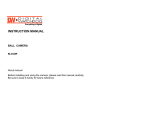
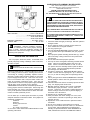
SCHEU PRODUCTS COMPANY, INCORPORATED
Mail: P.O. Box 5050, Upland, CA 91785-5050
Plant: 8855 Baker Ave., Rancho Cucamonga, CA 91730
TELEPHONE: 909 981-5343
ASSEMBLY AND OPERATING INSTRUCTIONS
UNIVERSAL MODELS 12-IR, 24-IR, 24-IRP, 36-IR, 48-IR
ALL PRO MODELS SPC-12, SPC-24, SPC-24P, SPC-36, SPC-48
INFRA-RED HEATERS
!
GENERAL HAZARD WARNING:
FAILURE TO COMPLY WITH THE PRECAUTIONS AND INSTRUCTIONS PROVIDED WITH THIS HEATER, CAN RESULT IN DEATH,
SERIOUS BODILY INJURY AND PROPERTY LOSS OR DAMAGE
FROM HAZARDS OF FIRE, EXPLOSION, BURN, ASPHYXIATION,
AND CARBON MONOXIDE POISONING.
TYPE OF GAS...........................For use with Propane Only
INPUT RATING....................................12-IR 11,000 BTU/hr
.............................24-IR/24-IRP 22,000 BTU/hr
........................................36-IR 33,000 BTU/hr
........................................48-IR 44,000 BTU/hr
MANIFOLD PRESSURE..........................28" Water Column
ORIFICE SIZE....................................................No. 69 Drill
!
WARNING: Improper installation, alteration,
service or maintenance can cause property damage,
injury, or death. Read the installation operating and
maintenance instrucitons thoroughly before installing or
servicing this equipment.
OPERATING INFORMATION
This is a propane, direct-fired, heater. It's intended use is
primarily temporary heating of buildings under construction,
alteration or repair.
!
WARNING:
NOT FOR HOME OR RECREATIONAL VEHICLE USE
Propane is heavier than air. If propane leaks from a connection or fitting, it sinks to the floor, collecting there with the
surrounding air, forming a potentially explosive mixture.
Obviously, propane leaks should be avoided, so set up the
propane supply with utmost care. Leak check new connections or reconnections with a soap and water solution and
follow all connection instructions herein. Also ask your
propane dealer for advice on the propane supply installation
and ask him to check it if there are any questions.
Direct-fired means that all of the combustion products from
burning propane enter the heated space. Even though this
heater operates very close to 100 percent combustion efficiency, it still produces small amounts of carbon monoxide.
Carbon monoxide (called CO) is toxic.
CO can build up in a heated space and failure to provide
adequate ventilation could result in death. The symptoms of
inadequate ventilation are:
headache
dizziness
burning eyes and nose
nausea
dry mouth or sore throat
So, be sure to follow advice about VENTILATION in these
operating instructions.
ONLY PERSONS WHO CAN UNDERSTAND AND FOLLOW THE
INSTRUCTIONS SHOULD USE OR SERVICE THIS HEATER.
IF YOU NEED ASSISTANCE OR HEATER INFORMATION SUCH AS
AN INSTRUCTIONS MANUAL, LABELS, ETC. CONTACT THE
MANUFACTURER.
SAFETY PRECAUTIONS
1. Check the heater thoroughly for damage. DO NOT operate a
damaged heater.
2. Do not modify the heater or operate a heater which has
been modified from its original condition.
3. Use only propane gas.
4. Use only VAPOR WITHDRAWAL propane cylinders. If there
is any question about vapor withdrawal, ask your propane
dealer.
5. Mount propane cylinders vertically (shutoff valve up). Secure
them from falling or being knocked over and protect them
from damage.
6. Do not direct heat toward propane cylinders.
7. Use only the hose and regulator assembly provided with the
heater. Inspect hose assembly before each use of the
heater. If there is excessive abrasion or wear, or hose is
cut, replace with hose assembly listed on parts list before
using heater. The hose and fittings shall be protected
from damage and deterioration.
8. For indoor or outdoor use. AREA MUST BE WELL VENTILATED. Provide minimum openings of 1 sq. ft. near the floor
and 1 sq. ft. near the ceiling (also see "Operating Information").
9. If at any time gas odor is detected, IMMEDIATELY DISCONTINUE operation until the source of gas has been located
and corrected.
10. Install the heater such that it is not directly exposed to water
spray, rain, dripping water and/or wind.
11. Maintain minimum clearance from normal combustible
materials (like paper) as follows: rear-2 ft.; sides-3 ft.;
front-6 ft. Locate 10 ft. from canvas or plastic tarpaulins or
similar coverings and secure them to prevent flapping or
movement due to wind action.
12. Operate only on a stable, level surface.
13. Since permanent skin tissue damage can occur, avoid
contact with the unit while it is operating or shortly after it
has been shut off.
14. Operate the unit in a draft-free area or protect the heater
from drafts.
15. Do not move, handle or service while hot or burning.
16. Use only in accordance with local codes or, in the absence
of local codes, with the Standard for the Storage and
Handling of Liquefied Petroleum Gases ANSI/NFPA 581998, and National Fuel Gas Code ANSI Z223.1/NFPA
!
WARNING; FIRE, BURN, INHALATION, AND EXPLOSION HAZARD. KEEP SOLID COMBUSTIBLES, SUCH AS BUILDING MATERIALS,
PAPER OR CARDBOARD, A SAFE DISTANCE AWAY FROM THE HEATER AS RECOMMENDED BY THE INSTRUCTIONS NEVER USE THE
HEATER IN SPACES WHICH DO OR MAY CONTAIN VOLATILE OR AIRBORNE COMBUSTIBLES, OR PRODUCTS SUCH AS GASOLINE,
SOLVENTS, PAINT THINNER, DUST PARTICLES OR UNKNOWN CHEMICALS.
OPERATING INSTRUCTIONS
PREPARING FOR OPERATION
1.
2.
3.
4.
5.
6.
7.
Inspect the heater for possible shipping damage. If any
is found, immediately notify the dealer.
Follow all of the “Safety Precautions” and “Operating
Information" on page 1, and “Propane Fuel Information” on page 4.
Refer to the exploded view on page 3 for general
assembly layout. Regulator: Heater is to be hooked up
to the regulator (set at 28” water column) supplied with
the heater.
HEATER ASSEMBLY:
a) Lay the heater reflector down down on a flat level
surface (the manifold mounting lug will be up).
b) Attach the manifold to the burner/reflector assembly as shown in the exploded view.
c) Be sure that the neck(s) of the manifold are
pushed all of the way into the one (1) inch tube(s)
of the burner assembly(s).
d) Position and tighten the adapter clamp(s).
e) The manifold mounting lug (the rectangular piece
of 1/8” thick steel that is welded to the manifold)
must face the direction shown in the exploded
view.
f) Attach the loose thermocouple end to the connection at the thermoelectric valve.
g) Tighten the connection finger tight, then tighten an
additional maximum ¼ turn using a 3/8” open end
wrench.
If you have the 24,000 BTU w/Piezo (all others go to
step7):
a) Place the piezo mounting bracket with the attach
ment surface on the left side of the manifold
mounting lug, the piezo bracket will cross over the
lug.
b) Lineup the mounting holes on the piezo bracket
and the lug, then securely attach the piezo bracket
to the lug with the two 10-24x3/8 machine screws
and hex nuts provided.
c) Insert the loose end of the electrode wire onto the
terminal on the piezo igniter.
HEATER MOUNTING (for Quad Heater go to step 7):
a) Assemble the flattened end of the heater support
to the manifold mounting lug with a lock bolt (3/816 x 1 ¼ bolt).
b) Place the 3/8-16 whiz nut onto the remaining 3/816 x 1 ¼ bolt, with the nut serrations away from the
bolt head.
c) Attach the lock bolt assembly into the remaining
base support weld nut, making sure that the nut
serrations face the base support.
d) Mount the heater onto a standard 20 or 40 #
propane cylinder by placing the slot in the heater
support over the propane cylinder flange. Tighten
the lock bolt assembly, then secure with the nut.
QUAD-HEAD HEATER MOUNTING
a) Mount the quad-head heater onto a 100# cylinder
Page 2
by placing the collar assembly over the threaded
neck (for cylinder valve cover) and tighten the wing
nut.
b) Place the slot in the heater support over the propane
cylinder flange.
c) Tighten the lock bolt assembly, then secure with the
nut.
8. Check the ‘O’ ring on the POL before each use (see page
4). Replace the ‘O’ ring if there is any sign of ware or
damage.
9. After the heater is securely attached to the propane
cylinder connect the POL fitting of the hose and regulator
assembly to the propane cylinder by rotating the POL nut
counterclockwise into the propane cylinder’s valve outlet. Securely tighten with a wrench.
10. Securely tighten all gas connections.
11. Open the cylinder’s gas valve and check all gas connections with a soap and water solution. DO NOT USE A
FLAME.
!
WARNING: DO NOT LOOK OVER TOP OF
HEATER (REFLECTOR) DURING IGNITION.
This heater may produce a small puff of flame
during ignition, which could result in serious
bodily injury.
START
1. Fully open the valve on the propane cylinder.
2. Depress the red button on the safety valve admitting gas
to the heater. Place a lighted match near the face of the
ceramic element using the hole located on the side of the
reflector. If the hose is filled with air, allow a few seconds
for gas to reach element. DO NOT LIGHT AT THE
ORIFICE.
3. 24-IRP: Depress the red button on the safety valve
admitting gas to the heater. Push and release the
piezo ignition button until the gas on the surface of the grid
ignites. this may take several strikes of the piezo.
Ignition may be observed using the holes located on the
sides of the reflector. DO NOT LOOK OVER TOP OF
REFLECTOR! If the hose is filled with air allow a few
seconds for the gas to reach the grids.
4. When the gas on the face of the ceramic element lights,
continue to hold the button depressed for 30 seconds,
then release. On multiple head units, check to see that
all elements are burning.
5. If the flame goes out, wait 5 minutes and repeat the
lighting procedure.
STOP
1. Securely close valve at propane cylinder.
2. Do not attempt to relight for 5 minutes.
RESTART AFTER SAFETY SHUTDOWN
1. Securely close valve at propane cylinder.
2. Wait 5 minutes.
3. Restart following "Start" procedure.
INSTRUCTIONS FOR ORDERING PARTS All parts orders must show Heater Model No., Item No., Part
No. and Description. Only parts supplied by the manufacturer
should be used on this unit. A locally purchased part may
appear to be identical, although in reality it might endanger the
heater or the persons operating the heater.
Item
No. Description
1
2
3
4
5
6
7
8
9
10
11
12
13
14
15
16
*
*
19
20
*
22
23
24
*
*
*
28
29
Burner Assembly w/ceramic grid
Hose Assembly
Support Tube Assembly
Reflector Assembly
Manifold Assembly
Bracket, Thermocouple
Orifice, LP #69 Drill
Keeper, Grid
Bracket, Electrode Ground
Bracket, Piezo Mounting
Bracket, Label
Nut, flange Lock 3/8-16
Clip, Thermocouple
Clamp, Loop 1" Dia.
Thermocouple, 12"
Regulator 28" W.C. 1/4 x 3/8 FPT
Manual, Operating Instructions
Label, Warning, Fuel
POL, Excess Flow 1/4 MPT
Piezo Igniter
Label, Hangtag
Nut, Piezo
Valve, Thermoelectric
Electrode
Label, Mode/Opr. Instructions
Label, Light Here
Label, Warning/Ignition Flash
Screw, Machine 3/8-16 x 1 1/4 Grd 5
Collar, Assembly, 48IR
The heater should be serviced only by a trained, experienced
service person.
Read the section on "Servicing" before ordering parts.
For parts order, call (909) 981-5343.
12IR
Qty.
24IR
Qty.
1010
1016
1017
1009
1014
3003
3008
3017
1
1
1
1
1
1
1
2
1010
1016
1017
1019
1021
3003
3008
3017
2
1
1
1
1
1
2
3
6042
6045
6069
6233
6257
6326
6369
6433
2
1
1
1
1
1
1
1
6042
6045
6069
6233
6257
6326
5369
6433
2
1
2
1
1
1
1
1
6712
1
6712
1
7285
1
7285
1
7608
7609
1
1
7608
7609
1
1
8190
2
8190
2
24IRP Qty.
1010
1016
1017
1019
1021
3003
3008
3017
3645
4291
4292
6042
6045
6069
6233
6257
6326
6369
6433
6473
6712
7161
7285
7395
7608
7609
8186
8190
2
1
1
1
1
1
2
2
1
1
1
2
1
2
1
1
1
1
1
1
1
1
1
1
1
1
1
2
36IR
Qty.
48IR
Qty.
1010
1016
1017
1022
1024
3003
3008
3017
3
1
1
1
1
1
3
4
1010
1016
1017
1025
1027
3003
3008
3017
4
1
1
1
1
1
4
5
6042
6045
6069
6233
6257
6326
6369
6433
2
1
2
1
1
1
1
1
6042
6045
6069
6233
6257
6326
6369
6433
2
1
2
1
1
1
1
1
6712
1
6712
1
7285
1
7285
1
7608
7609
1
1
7608
7609
1
1
8190
2
8190
1028
2
1
SERVICING
A hazardous condition may result if a heater is used that
has been modified or is not functioning properly. When the
heater is working properly:
The flame is contained near the surface of the
ceramic grid(s).
The flame is essentially blue.
There is no strong disagreeable odor, eye burning or
other physical discomfort.
There is no smoke or soot internal or external to the
heater.
There are no unplanned or unexplained shutdowns of
the heater.
The parts list shows the heater as it was constructed. Do
not use a heater which is different from that shown. In
this regard, use only the hose, regulator and cylinder
connection fitting (called a POL fitting) supplied with the
heater. Do not use alternates. For this heater, the
regulator must be set to supply 28" water column (W.C.)
outlet pressure (1.0 psig). If there is any uncertainty
about the regulator setting, have it checked.
WARNING
Local codes for installation of propane systems may vary
considerably. Therefore, ask your local propane supplier
for advice on propane system installation in your particular
area. In the absence of local codes, install in accordance
with American National Standards Institute (ANSI)/National Fire Protection Association (NFPA) publication 581998 Standard for the Storage and Handling of Liquefied
Petroleum Gases and ANSI Z223.1/NFPA 54 National Fuel
Gas Code. Your supplier, fire marshal or library should
have copies of these standards.
The propane supply system must be arranged for vapor
withdrawal. Propane cylinders must be secured in the
upright position to keep them from falling or being knocked
over.
MINIMUM RECOMMENDED PROPANE CYLINDER SIZE:
HEATER MODEL
CYLINDER SIZE
OPERATING TIMES
@60oF*
12IR/SPC-12IR
20# (5- Gallons)
30 - hours
24IR/SPC-24IR
20# (5 - Gallons)
15 - hours
A heater which is not working right must be repaired, but
only by a trained, experienced service person. Contact
the factory for the service center closest to you, phone
number (909) 981-5343.
24IR/SPC-24IRP
20# (5 - Gallons)
15 - hours
36-IR/SPC-36IR
40# (10 - Gallons)
20 - hours
48IR/SPC-48IR
100# (25 - Gallons)
35 - hours
You may also obtain in-warranty or out-of warranty service
by returning the product freight prepaid to:
* If ambient temperatures will be less than 60oF increase
propane supply accordingly.
Scheu Products Company
8855 Baker Avenue
Rancho Cucamonga, CA 91730
In-warranty products returned to the Service Department
will be repaired with no charge for either parts or labor and
will be returned to you freight prepaid. Please include a brief
statement indicating date, place of purchase, the nature of
the problem and proof of purchase.
Out of warranty products returned to the Service Department will be repaired with a charge for parts and labor and
will be returned to you freight collect.
PROPANE FUEL INFORMATION
During use, liquid propane in a container vaporizes. As it
vaporizes, the propane cools itself. This cooling process
is known as the refrigeration effect. If it continues long
enough and proceeds fast enough, the propane temperature and pressure will fall so low that heater operation may
be improper or even impossible even though plenty of
propane remains in the container. Often frost forms on the
outside of the propane container as a warning of excessive
refrigeration.
Recommendations to reduce the ill effects of refrigeration
effect are:
MAINTENANCE AND STORAGE
1. The heater should be inspected before each use, and at
least annually by a qualified person.
2. Before each use, check the soft "O" ring seat at the
bullnose of the POL fitting. If the "O" ring is cut, scuffed,
or otherwise damaged, replace it with part number 6681.
3. Turn off the gas at the LP-gas supply cylinder(s) when
the heater is not in use.
4. When the heater is to be stored indoors, the connection
between the LP-gas supply cylinder(s) and the heater
must be disconnected and the cylinder(s) removed from
the heater and stored outdoors and in accordance with
Chapter 5 of the Standard for Handling of Gases ANSI/
NFPA 58-1998.
Provide considerable more propane than you plan to
consume. As a rule of thumb, provide twice as much.
Fill containers frequently, especially in cold weather.
Never allow propane to fall below one-third of container capacity.
If possible, keep containers in a warm area (under
no circumstances should the heater exhaust be
directed toward the propane container).
SEPTEMBER 2000
6326P
Page 4