1
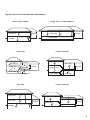
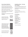
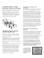
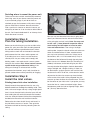
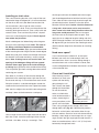
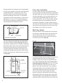
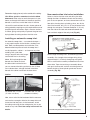
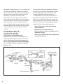
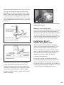
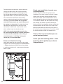
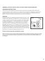
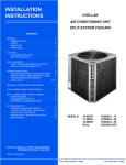
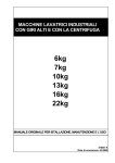
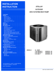
Index
Typical installations
2
Components of system
3
Seven Step Installation
Step #1: Choose your system
3
Step #2: Plan number of inlets
4
Step #3: Plan placement of inlets
4
Step #4: Plan tubing installation
5
Step #5: Install inlet valves
Existing home
5
New construction
8
Step #6: Install tubing
9
Step #7: Install power unit
Safety warnings
10
12
Typical Central Vacuum System Installations
Single story on slab/crawlspace
Ranch-style bungalow
MAIN FLOOR
1
BASEMENT
3 GARAGE
MAIN FLOOR
4-level split
Large 4-level split
UPPER LEVEL
MAIN FLOOR
1
UPPER LEVEL
1
LOWER LEVEL
GARAGE
3 3
2
CRAWLSPACE
3
2
1
MAIN FLOOR
3
3
GARAGE
LOWER
GARAGE
5
LEVEL
2
2
4
CRAWLSPACE
CRAWLSPACE
BASEMENT
Large 3-level split
Two-story
1
UPPER LEVEL
BASEMENT
1
UPPER LEVEL
1
MAIN FLOOR
MAIN FLOOR
2
4
GARAGE
3
LOWER LEVEL
2
BASEMENT
3
4
4
GARAGE
CRAWLSPACE
2
Seven Step Installation
Congratulations on the purchase of your new
central vacuum system. It will make cleaning your
home easier and improve indoor air quality. The
system typically can be installed in virtually any home
with no costly alterations and very little mess. This
guide will show how to install your central vacuum
system in your home in just seven steps.
Before you begin installation, read this guide. Also
review local building codes so your installation
complies with them.
Installation Step 1: Choose
your system.
You’ve already completed step number one...you’ve
purchased your powerful new system. Next, inventory
the component parts that arrived with your central
vacuum system kit and assemble the tools you will need.
(See front cover.)
Inventory all the parts.
Lay out the parts so you know you have them all
and what each is called. A three-inlet valve system
typically includes:
Components of a central vacuum system
installation.
80' low-voltage wire
3 mounting brackets
6 nail guards
The Power Unit/Dust Collection
Receptacle is usually mounted in
the garage, basement, utility or
storage room to remove dust and
3 plaster guards
allergens from living areas.
2 90 degree sweep tees
1-1/4 pint solvent sealer
6 45 degree elbows
9 90 degree sweep elbows
6 stop couplers
3 90 degree dual elbows
6 hanger clamps
6 wire nuts
Tubing & Fittings: Dust and dirt are
carried through tubing from “inlet
valves” to the power unit. Note:
ASTM tubing and fittings are
specifically designed for your
central vacuum system. Other
types of tubing, like plumbing pipe,
are different sizes and will not fit.
Inlet valves: Installed in the wall or
floor, each inlet valve connects the
powerhead and flexible cleaning
hose to the tubing in your home.
3
3 floor mounting adapters
*Inlet covers sold separately
Installation Step 2: Decide
how many inlets you will need.
To make sure your central vacuum system reaches
every room throughout the house, you must first
determine the number of inlets you will need and
where to place them. One inlet valve can serve
700-800 square feet (63-72 sq m). Use only interior
walls if possible, so you won’t have to deal with
insulation typically found in exterior walls.
Choosing the right spot for the
inlet valve.
Use a stud finder, or sound out the wall, to make sure
the site for the inlet valve is between the studs and
that the space is open behind the wall board. Also
check the other side of the wall to make sure it’s clear
of obstructions such as utilities and outlets. Caution:
Do not install an inlet behind a door or in a wall
that has a pocket door. Then have a helper hold the
end of the hose at the proposed site for the inlet valve
and take the other end and walk around the room(s).
If you have no helper, use a piece of cord or string
that is 30 feet (9.15m) long—the length of the hose.
You want to be able to reach everywhere from floor to
ceiling even with furniture in the way. You may have
to choose a different location or add another inlet to
cover the entire floor. Remember, one inlet usually lets
you cover about 700-800 square feet (63-72 sq m).
Repeat this on each floor of your home.
What about installing inlet valves
upstairs?
Installation Step 3: Decide
where to place inlets.
Good locations are centrally located in hallways or
closet walls and/or doorways. Do not place inlets
behind doors or furniture.
Existing home: The inlet valve must be within 6 feet
(1.83m) of an electrical outlet to provide power to the
powerhead. A switch on the handle sends a signal
through “low-voltage” (24 volt) wiring to turn the power
unit on and off.
New construction: If your home is under construction,
you should consider using “electrified” inlet valves.
Electrified valves have low-voltage and household
wiring connections built in, so there’s no need for
a nearby electrical outlet. Inlet valves should be
installed before drywall is hung. Installation must
be coordinated with an electrician to hook up the
electrical line after the tubing has been installed
(electrified valves sold separately).
Because there are finished walls above and below the
second-floor sole plate, installing inlet valves upstairs
can take a little more ingenuity. There are several
options: Place an inlet outside a closet wall and then
run the tubing through the wall and through the inside
of the closet and down (see Fig. 03, Page 07).
Another option is to run the tubing up into the attic
then across and down to the inlet. Yet another
solution is to install the upstairs inlet valve directly
into the floor. Note: Although plastic inlet valves
are acceptable as long as they’re installed next
to the wall where no one will step on them, metal
floor inlets provide added durability. Hint: Do not
install floor inlets where furniture will be.
To run tubing through a
closet, mount the inlet
outside the closet and
run tubing into the closet
and down through the
closet floor.
4
Deciding where to mount the power unit.
To be sure that dust and dirt are effectively removed
from living areas in your home, mount the power unit
in your attached garage. If you do not have an
attached garage, the basement, utility room, storage
room or mud room is the best alternative location.
Find a spot that is close to an electrical source, yet
with plenty of room for air to circulate on either side of
the unit. You’ll need a dedicated 15- or 20-amp circuit.
Check the owner’s manual.
Installation Step 4:
Plan the tubing installation.
Before you install tubing to carry dust and dirt to the
power unit, plan your route. Run the tubing beneath
the sub-floor whenever possible because it makes
tubing easier to work with and creates the shortest
path between the inlet valves and the power unit.
If the tubing has to run next to a water heater or
chimney flue—for your safety and to comply with
building codes—use metal central vacuum system
tubing for that section. Hint: A local central vacuum
system dealer may provide metal tubing. If the
tubing runs through an unheated attic or other
unprotected environment, wrap it with insulation to
prevent condensation and the possibility of clogging.
Installation Step 5:
Install the inlet valves.
Existing home inlet valve installation.
Directly beneath the proposed inlet site, use a flatbladed screwdriver to wedge the molding aside. Then,
take a wire coat hanger and snip a long straight piece
from it. Insert the wire into the chuck of your drill and
then holding the drill vertically beneath the intended
inlet site, slowly drill down into the floor alongside the
baseboard or where the wall and floor intersect.
Release the wire from the drill chuck and leave it in
the pilot hole to serve as a locator. Then go to the
basement and look for the wire protruding from the
ceiling.
5
Now you can see where the inlet valve is going to be
above you. Measure from the wire to find the center
of the sole plate and wall cavity. Note: You may want
to drill a 3/4" (1.9cm) diameter inspection hole to
avoid cutting into the bottom of a stud or other
inner-wall obstructions. Then using a flashlight
and/or probe, inspect the interior of the wall to be sure
there are no obstructions. If there are obstructions,
you may have to move the inlet site. If there are no
obstructions, drill a 2-1/4" diameter hole (5.7cm) in
the bottom of the hollow wall through the sole plate.
Make sure to cut in between the walls. The tubing is 2"
(5.08cm) in diameter, so the hole will give you room
to manipulate the tubing. Again, check for obstructions
using a flashlight and a length of tubing. If there are
no obstructions, go back upstairs and mark the inlet
location on the wall. To do that, at the electrical outlet
adjacent to the inlet site, measure up from the floor
to the center of the outlet. At the proposed inlet site
measure up from the floor the same distance. This will
be the center of your inlet valve. If you prefer, you may
locate the inlet at a more convenient height. Some
homeowners prefer the inlet at fingertip height, about
30" (76.2cm) above the floor.
Installing an inlet valve.
Take a wall mounting bracket, cut or snap off the new
construction flange and dispose of it. In new construction,
nail the tab to the stud. (See New Construction inlet
valve installation.) Use a level to make sure the
mounting bracket is level. Then trace the outline of the
mounting bracket onto the wall. Take a utility knife and
score the lines. Then use the utility knife or a drywall
saw to cut a hole though the drywall. Hint: A drywall
saw makes the job easier.
Attach a 90 degree dual elbow fitting to the flange on
the back of the mounting bracket. Note: The ends of
the fitting are different depths to accommodate
walls of different widths. Apply glue around the outside
of the mounting bracket flange and twist the 90 degree
elbow fitting into place. Make sure the open end faces
the direction it will meet the tubing—usually straight
down. Note: If tubing has to run from the attic, the
opening of the 90 degree fitting will face upward.
Caution: Never apply glue to the inside of fittings
or tubing. Apply glue only to the outside of the tubing.
This will prevent glue from creating obstructions which
could clog your system.
Run about 6" (15.24cm) of low-volt wire through the
guide hole in the mounting bracket. Split the wire into
two strands and strip 1" of insulation from each strand.
Wrap the strands in a clockwise direction around the
screws on the back of the inlet valve. Tighten the screws.
Now attach a weight to the end of the low-voltage wire
and drop it down to the basement or crawlspace.
Have a length of wire coat hanger ready with one end
bent into a hook. Insert the mounting bracket into the
wall hole...first down...then up...centering it. Take
the hanger and insert the hooked end of the hanger
into the 90 degree elbow to hold the bracket in place.
Then, slide the inlet valve along the wire hanger into
the mounting bracket. Screw the valve into place.
Remove the wire hook. Caution: Inlet kits come with
a long and a short screw, so be sure to use the
short screw in the hole facing the elbow since the
long screw could puncture it. Be sure to mount
the inlet valve so the lid pulls down to open. Then
apply glue to an adequate length of tubing and aim it
upward through the hole in the sole plate and into the
90 degree fitting on the back of the mounting bracket.
(See Installation Step #6 for information on installing
tubing.)
Need more space?
If you cannot locate a hollow wall, or the space
between your walls isn’t wide enough, there are
two alternatives: One is to run the tubing through a
concealed area such as the inside of a closet; then
run the tubing downward. Another alternative is to use
a floor mounted inlet.
Closet wall installation.
Often the only practical
Fig. 01
solution is to install your
system with the tubing
going through a wall
into a closet, then down
through the closet floor.
To use this method,
select a suitable inlet
valve location outside a
closet—exercising the
Closet Wall Installation In
same precautions as for
An Existing Structure
normal wall installation.
Then, using a length of coat hanger, drill a hole
through both walls (Fig. 01). Hold the wire perfectly
horizontal so the interior and exterior holes line up
with one another. Check for inner wall obstructions by
bending a short length of coat hanger wire at a right
angle and twirl the right angle piece inside the wall. If
there are no obstructions, drill a 2-1/4" (5.7cm) hole
horizontally through both walls.
6
Enlarge the hole in the exterior wall to accommodate
the inlet valve assembly (valve and mounting bracket).
(As described above in “Installing an inlet valve.”)
Inside the closet, drill a pilot hole through the floor
beneath the opening in the wall or at a convenient
spot nearby to check for obstructions. If there are no
obstructions, cut a 2-1/4" (5.7cm) hole through the
floor. Run low-voltage wire through the hole in floor,
and through the wall to exterior of closet.
Fig. 02
Floor valve installation.
To install a floor inlet valve, drill a pilot hole with a
wire coat hanger and check the location as previously
described. When you are sure that the proposed location
will not be blocked by a joist or other obstruction, cut
a hole in the carpet slightly larger than your 2-1/4"
(5.7cm) drill bit. Drill a 2-1/4" (5.7cm) hole in the floor.
Enlarge the opening to accommodate the low-volt
connections. Assemble an adapter reducer bushing
and attach the low-volt wire to the inlet valve. Drop the
low-volt wire to the basement. Screw the valve to the
floor. Repeat until all inlets are installed.
Multi-story homes.
Inner-Wall Closet Assembly
Pass low-voltage wire through the wire guide hole in
the inner wall closet assembly (Fig. 02) and tape or
cable tie low-voltage wire to this assembly immediately
behind the bracket. Attach wires to low-voltage terminals
on the back of the inlet valve. Place the inner wall
assembly lengthwise through the wall opening and
arrange the assembly so the bracket is flush with the
inside surface of the wall. Screw the inlet valve to the
wall (Fig. 03).
Fig. 03
Inner-Wall Closet Assembly – Installed
7
Multi-story homes usually require one or more inlets
on each level. Instead of trying to line up inlet valves
from one level to the next, run a separate line of
tubing from the upstairs inlet valve to a branch line
or to the main trunk line (Fig. 04).
Fig. 04
In a two-story home, upstairs beneath the site you’ve
selected for the inlet valve cut a hole just large
enough to allow you to reach the second-floor sole
plate. Hint: Cut the hole low in the wall for easier
drilling through the sole plate. Cut a 2-1/4" (5.7cm)
hole in the sole plate. Install the inlet valve just as
before. Then, from the basement, insert a length of
tubing long enough to reach through the hole in the
second floor sole plate to the site for the inlet valve.
You may have to join several lengths of tubing.
Measure and pre-cut these pieces and test-fit them
before gluing. When you do apply glue, work quickly
to prevent the glue at the top end of the tubing from
drying out before it reaches the fitting at the inlet valve.
Remember: Apply glue only to the outside of the tubing.
Hint: When upstairs, remember to aim the elbow
downward. Other ways to reach the upstairs in your
home are through the interiors of closets or pantries,
beneath a staircase, or with floor inlets. If the inlet
valve will be serviced from the attic, shorter pieces of
tubing joined by couplings may be required because of
overhead space restrictions. Again, measure and test
fit. When gluing, work quickly to prevent the glue from
drying before the tubing reaches the inlet valve.
New construction inlet valve installation.
Select a site for the inlet valve and drill a pilot hole
through the floor. Go below to check that the tubing
path is clear of present, or future, obstructions such as
floor joists, heating ducts, plumbing, wires, etc. At the
inlet valve location, drill a 2-1/4" (5.7cm) diameter hole
through the sole plate. The hole should be 2" (5.1cm)
from the side of the stud and centered between the
front and back edges of the sole plate (Fig. 05).
Fig. 05
Installing an automatic sweep inlet.
An automatic sweep inlet — an automatic dustpan —
a very popular option for the kitchen, mudroom and
bath. Here are some pointers for installation. First,
determine the best place to install the sweep inlet —
usually beneath a cabinet — and remove any shoe
molding. Drill a pilot hole
using a length of wire coat hanger
and find the wire in the ceiling
below. Drill up through the floor
beneath the cabinet to check
for obstructions and make sure
you can connect the tubing to the main line. If there
are no obstructions, enlarge the hole in the floor
beneath the cabinet and check the clearances.
VacPan
VacuSweep
Cut hole 6-3/4" x 1-3/4"
(17.15cm x 4.45cm)
Cut hole 6-5/8" x 2-3/8"
(16.83cm x 6.04cm )
Now, return to the kitchen/mudroom/bath to measure
and saw the rectangular hole for the sweep inlet and
fasten the inlet into place. In the basement, attach
the tubing and string the low-voltage wire just as you
would for any inlet. Hint: See sweep inlet manual for
details.
Glue a length of tubing into a stud-mounting bracket
assembly. Cut a length of low-voltage wiring, bring
approximately 6" (15.24cm) through top wire guide
hole in stud bracket assembly and double it back into
elbow hole. Tape wire to tubing at assembly elbow
and again close to end, and tuck remaining wire into
bottom of tubing. Screw plaster guard onto face of
assembly (Fig. 06).
Fig. 06
Stud-Mounting Bracket Assembly (New Construction)
8
Drop bottom of tubing through 2-1/4" (5.7cm) hole and
nail stud-mounting bracket assembly to stud. Make
sure the center of the inlet hole is at the correct height
above floor level and the tubing extends below the
sub-flooring. To prevent a nail or screw from
penetrating the vacuum tubing, install nail guards
on the sole or top plates adjacent to the tubing. See
“Installation Step Six: Install the tubing” and complete
tubing installation as much as possible. After the
walls are finished and painted, plaster guards can be
removed and inlet valves installed. The tubing system
may be completed at that time and the power unit
installed.
Installation Step 6:
Install the tubing.
(Existing Home or New Construction)
Beginning at the inlet farthest from the power unit,
temporarily fasten tubing for the main trunk line into
position. Hint: Loop string or low-voltage wire to
create a hanger strap from a nail or overhead pipe,
etc., to cradle the tubing — holding it in position
while you work.
9
Push a length of tubing up into bottom of the elbow
on the inlet valve assembly. Piece together sections
of tubing without glue at first to make sure things
fit properly. Mark the connections so you can
re-assemble them the same way. Remember, the
tubing enters the fitting approximately 3/4" (1.9cm).
Measure, cut, and de-burr tubing, and, using a 90
degree sweep elbow, slip-fit the vertical tubing line to
the main horizontal line. To avoid potential clogging
problems when installing tubing and fittings:
• Make straight cuts on tubing (pipe/tubing
cutter works well).
• Remove burrs from ends of tubing.
• Be sure tubing fits against the shoulder of the
fitting with no gaps.
• Glue only the outside edge of the tubing before
assembly into fittings.
Connect tubing from additional inlet valves to the main
trunk line using 90 degree sweep tee elbow fittings.
(Fig. 07) and use clamps to hold the sections in place.
Be sure to install the sweep tee fittings so the sweep
is toward the power unit (Fig. 08). Always run branch
lines from the sides or top of the main trunk line, never
out of the bottom because this will create a trap for dirt
to fall into.
Fig. 07
Hint: Create clamps from extra tubing to hold lowvoltage wire in place.
Masonry or concrete walls.
If you have to run tubing through masonry or concrete
walls, rent a hammer drill and/or masonry hole saw.
Run the tubing through and patch the hole once you’re
up and running. Before drilling, check local building
codes for special firewall penetration regulations. The
code also should tell you if steel tubing is required.
Typical Under-Floor Installation
Fig. 08
90 Degree Sweep Tee
String the low-voltage wire along as you assemble
the tubing. Join or splice low-volt wires with wire
connectors at each junction or branch in the tubing.
To make sure the polarity is right, always attach wires
of the same color to each other — typically copperto-copper and silver-to-silver. Proceed until the tubing
system is complete.
Installation Step 7:
Install the power unit.
Attach the power unit to the wall with the bottom
screws of the mounting bracket located 48" (1.2m)
above the floor to allow easy removal of the dirt
canister. For proper motor cooling, there must be at
least 12" (30.48cm) between the unit and the ceiling.
Do not install the power unit where the ambient
temperature regularly exceeds 120 degrees
Fahrenheit (48.9 degrees C).
If mounting on plaster, wall board or panel walls,
be sure mounting bolts enter studs. If mounting on a
block or concrete wall, drill the holes with a masonry
bit and insert plastic or lead anchors. As an alternative
to mounting on concrete walls, suspend 2" x 4" (5.1cm
x 10.16cm) studs or plywood from overhead.
10
To attach the low-voltage wires, strip the wire and
crimp the strands into the two “slip-on” terminals
provided. Attach the terminals and plug the power
unit into the dedicated electrical outlet. The sentry
light should come on. Flip the switch and the power
unit should come to life. Attach the remaining
section of tubing to the power unit with connector/s
and clamp/s provided. Caution: Do not glue the
connection because you may need to disconnect
the system at a future date. For added installation
convenience, some power units may have inlet
connections on either side. If your system came
with a muffler, clamp it to the exhaust port.
NOTE: Unit may be exhausted to exterior. Use
the same tubing and fittings. If vented, the exhaust
air should not be vented into a wall, ceiling or
concealed space of a building. Venting over
10 feet (3m) is not recommended.
Power unit electrical wiring.
Check local codes but use not less than #14-3 wire.
Plug power unit cord into appropriate 120/220/230/240V
— 50/60 cycle electrical outlet. Be sure line voltage
is sufficient to handle a 15- or 20-amp load. See your
owner’s guide.
11
Check your installation to make sure
it works properly.
All that’s left to do is check the quality of your
installation. First, check to see if you have a closed
system; with no hose or handle attached, and all
inlet valves closed, there should be little or no air
coming through the exhaust on the power unit when
it is turned on. Second, with the system still running,
walk through your home. If you hear whistling or
hissing, you may have forgotten to glue a connection.
Check basement and attic areas, too. Third, have a
helper plug the hose into each of the inlet valves to
be sure you can turn the power on. Turn off the switch
on the hose handle and the unit should turn off.
That’s it! You’ve just installed your own
central vacuum system.
You’ve just made cleaning easier... while
improving the air quality in your home.
Congratulations!
WARNING: ELECTRIC SHOCK COULD OCCUR IF USED ON WET SURFACES.
GROUNDING INSTRUCTIONS
This appliance must be grounded. If it should malfunction or break down, grounding provides a path of least
resistance for electric current to reduce the risk of electric shock. This appliance is equipped with a cord that has an
equipment-grounding conductor and grounding plug. The plug must be plugged into an appropriate outlet that is
properly installed and grounded in accordance with all local codes and ordinances.
WARNING
Improper connection of the equipment-grounding conductor can result in a risk
of electric shock. Check with a qualified electrician or service person if you are
in doubt as to whether the outlet is properly grounded. Do not modify the plug
provided with the appliance—if it will not fit the outlet, have a proper outlet
installed by a qualified electrician. This appliance is for use on a nominal
120-volt circuit and has a ground plug that looks like the plug illustrated in
(Fig. 09) for North American units. For 220/230/240 volt units, consult your local
building code/electrician. Make sure that the appliance is connected to an outlet
that has the same configuration as the plug. No adapter should be used with
this appliance. Check power unit On/Off switch and all inlet valves for operation.
This power unit is intended for household and commercial use.
Fig. 09
'2/5.$%$
/54,%4
"/8
'2/5.$%$
/54,%4
'2/5.$%$0).
Read all instructions before using this vacuum.
NOTE: Your central vacuum system is listed and approved by the appropriate agencies for dry pick-up only.
Please see your rating plate for details. To reduce the risk of electric shock, DO NOT USE outdoors or on
wet surfaces.
12
IMPORTANT SAFETY INSTRUCTIONS
When using electrical appliances, basic safety precautions should always be
followed, including the following:
DANGER: Always unplug power unit from the electrical outlet before servicing and
cleaning.
WARNING: To reduce the risk of burns, fire, electric shock or injury to persons:
1. Keep cord away from heated surfaces.
2. Do not allow to be used as a toy. Close supervision is necessary when this vacuum is used by or near children.
3. Use this vacuum only for its intended use as described in the operating and maintenance manual. (Use of
attachments not recommended by the manufacturer may cause fire, electric shock or injury.)
4. Never operate this vacuum if it has a damaged cord or plug, if it is not working properly or if it has been dropped
or damaged. Return to service center or have service person examine and repair.
5. Do not pull or carry this power unit by supply cord, use cord as a handle, close a door on cord or pull cord around
sharp edges or corners.
6. Never disconnect plug by pulling on cord. To disconnect from outlet, grasp the plug, not the cord.
7. Do not put any object into openings. Do not use with any opening blocked; keep free of dust, lint, hair and
anything that may reduce air flow.
8. Keep hair, face, fingers and loose clothing away from any openings.
9. Do not pick up cigarettes, live hot ashes, matches or similar materials.
10. Never operate vacuum without dust bag and/or filter in place.
11. To disconnect, turn all controls to the OFF position; then remove plug from outlet.
12. Never handle plug, cord or power unit with wet hands.
13. Electric shock could occur if used on wet surfaces.
14. Use extra care when cleaning on stairs.
15. Do not use to pick up flammable or combustible liquids such as gasoline or use in areas where they may be present.
16. For a grounded appliance: Connect to a properly grounded outlet only. See grounding instructions.
SAVE THESE INSTRUCTIONS
13