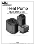
1
Pool and Spa
Heat Pump
Owner’s Manual
and
Installation Guide
PN: LTP0009
01/12/04
Models:
T65
T115
T135
(Also Applies to All C115 Models)
ATTENTION INSTALLER:
THIS DOCUMENT IS PURCHASER’S PROPERTY AND IS TO REMAIN WITH THE HEAT PUMP OWNER
1/7/041
1-800-786-7751
NOTES
___________________________________________________________________________________
__________________________________________________________________________________
___________________________________________________________________________________
_________________________________________________________________________________
_________________________________________________________________________________
_________________________________________________________________________________
___________________________________________________________________________________
__________________________________________________________________________________
___________________________________________________________________________________
_________________________________________________________________________________
__________________________________________________________________________________
________________________________________________________________________________________
___________________________________________________________________________________
____________________________________________________________________________________
_________________________________________________________________________________
__________________________________________________________________________________
_________________________________________________________________________________
__________________________________________________________________________________
2
__________________________________________________________________________________
TABLE OF CONTENTS
WELCOME TO THE TEAM ------------------------------------------------------------------ 4
IMPORTANT FEATURES OF YOUR NEW HEAT PUMP -------------------------------- 5
SAFETY INFORMATION --------------------------------------------------------------------- 6
QUICK START & STOP ----------------------------------------------------------------------- 8
PHYSICAL CHARACTERISTICS & PERFORMANCE ----------------------------------- 9
Dimensional Information - TropiCal Models T65 and T115 --------------------------- 9
Dimensional Information - TropiCal Model T135 -------------------------------------- 10
TropiCal: Table of Specifications--------------------------------------------------------- 11
Refrigerant Circuit Performance Charts ------------------------------------------------- 11
Guide: Troubleshooting Refrigerant Circuit Problems --------------------------------- 13
INSTALLATION -------------------------------------------------------------------------------- 14
Placement of Heater ------------------------------------------------------------------------- 14
Plumbing Requirements --------------------------------------------------------------------- 16
Electrical Requirements -------------------------------------------------------------------- 18
START-UP & OPERATION ------------------------------------------------------------------- 20
Overview of Controls------------------------------------------------------------------------ 21
Initial Start-up and Basic Operation ------------------------------------------------------- 21
Heating Tips ---------------------------------------------------------------------------------- 22
Calculating Initial Heating Time ----------------------------------------------------------- 23
MAINTENANCE ------------------------------------------------------------------------------- 24
Planned Maintenance ----------------------------------------------------------------------- 25
General Maintenance ----------------------------------------------------------------------- 25
Maintaining Proper Water Flow ----------------------------------------------------------- 26
Maintaining Proper Clearances Around Heater ------------------------------------------ 27
SEASONAL USE & SHUT DOWN ---------------------------------------------------------- 27
During the Swim Season -------------------------------------------------------------------- 27
Freeze protection / Extended Shut Downs ------------------------------------------------ 27
Winterizing (Hard Freeze Conditions) --------------------------------------------------- 27
TROUBLESHOOTING ------------------------------------------------------------------------ 29
Common Troubleshooting Issues ---------------------------------------------------------- 29
Troubleshooting Flow Charts --------------------------------------------------------------- 30
REPLACEMENT PARTS --------------------------------------------------------------------- 34
CONTACTING THE FACTORY -------------------------------------------------------------- 35
3
Welcome
to the
Team
Dear Owner:
C
ongratulations on your wise decision to make an AquaCal heat pump part of your home. Since
1981, AquaCal has maintained the worldwide lead in the manufacture of swimming pool & spa
heat pumps. Your new heat pump is not only a
great investment, but also the most cost effective method
available for heating pools and spas. For example, as a
means to heat pool or spa water, your heat pump is up to
400% more efficient than gas, and, when compared to
electric resistance heat, your heat pump is nearly 600%
more effective. You can rest assured that your new heat
pump is of the highest quality and efficiency, and is
designed and built to provide years of trouble-free
operation.
Moreover, should you decide you would like
AquaCal to provide regular inspection and maintenance
for your heat pump—which we do recommend—you
will find AquaCal has the largest and best-qualified
service staff in the pool & spa heat pump industry.
4
“You can rest assured
that your new heat
pump is of the highest
quality and efficiency,
and is designed and
built to provide years of
trouble-free
operation.”
IMPORTANT FEATURES OF
YOUR NEW HEAT PUMP
ThermoLink Heat
Exchanger:
a
a
a
ThermoLink
Heat Exchanger
Electronic
Controller:
The heart of your heat
State-of-the-art, solid-state
pump is the patented
electronic controller, mainThermoLink heat extains water temperature
changer. The primary
within 1ºF of set point. Concause of premature
troller also permits user to
heat pump demise is
predefine different Pool and
the failure of the heat
Spa water temperature set
exchanger. Ordinary
(135-Series)
points.
heat exchangers are
made from a cupronickel alloy. This cuCorrosion-Resistant
pronickel material is
Cabinet:
susceptible to attack
Hybrid design utilizes the best
from the sanitizers used in pools and spas, and from features of finished aluminum and resilient ABS plasother related water chemistry conditions. Once the heat tic. The base, being ABS material, will never rust or
exchanger fails, the heat pump is ruined. The corrode. The remainder of the cabinet is constructed
ThermoLink heat exchanger tube is made from tita- from sturdy, marine-grade, powder-coated aluminum.
nium, and is virtually impervious to water-chemistry
damage.
Electronic Controller
Corrosion-Resistant
Cabinet
PLEASE SPEND A FEW MINUTES READING FURTHER TO BECOME
FAMILIAR WITH ALL THE FEATURES, THE SAFE OPERATION, AND THE
CARE OF YOUR NEW HEAT PUMP.
5
SAFETY INFORMATION
Used and maintained properly, your heat pump will provide year-upon-year of safe and economical service.
However, as with any mechanical or electrical device, to get the most from your heat pump–while insuring
personal safety for you and others–certain operational and maintenance factors must be observed.
Likewise, excepting a few minor owner-capable maintenance items (explained later in this manual), repair and
service of your heat pump must be performed only by experienced service personnel. Should you, the owner,
suspect your heat pump is not performing properly, by referring to the section in this manual entitled:
"Troubleshooting", you will be able to determine if a call for service is required. Your installer can be one source
of service, or AquaCal Customer Support personnel stand ready to assist you at: (800) 786-7751. For questions
concerning installation, modifications, operation, service and upkeep, please contact your installer or AquaCal
Customer Support. Warranties may be voided if the heater has been used, maintained, or repaired improperly.
In addition to possible voiding of warranties: unapproved installation methods, nonstandard modifications, poor or
incorrect maintenance, service by unqualified personnel, or improper use of this unit, may result in personal injury
and/or property damage. For personal safety and to avoid damage to equipment, it is important that safety
instructions displayed on the heat pump, and within this manual, are read, understood, and followed.
Throughout this manual the following two safety signals are placed where particular care is required. Please note
"WARNING" relates to personal safety, while "CAUTION" signals promote avoiding damage to equipment.
WARNING !
Failure to heed the following may result in permanent injury or
death.
This “Warning” symbol appears in this manual where special attention is required for personal safety.
Specific instructions will appear in this box.
CAUTION !
Failure to heed the following may result in damage to equipment.
This “Caution” symbol appears in this manual where special care is required to avoid equipment damage.
Specific instructions will appear in this box.
Water Temperature Safety
WARNING !
Failure to heed the following may result in permanent injury or
death.
Prolonged immersion in water warmer than normal body temperature may cause a condition known as
HYPERTHERMIA. The symptoms of hyperthermia include: unawareness of impending hazard, failure
to perceive heat, failure to recognize the need to exit the spa and unconsciousness. The use of alcohol,
drugs, or medication can greatly increase the risk of fatal hyperthermia. In addition, persons having an
adverse medical history, or pregnant women should consult a physician before using a hot tub or spa.
Children and the extreme elderly should be supervised by a responsible adult.
6
Heater NOT Repairable by Owner
WARNING !
Failure to heed the following may result in permanent injury or
death.
Heat pumps contain no owner-repairable components. Repairs must not be attempted by untrained
and/or unqualified individuals. If service is deemed necessary, contact installing dealer or AquaCal
Customer Support at (800) 786-7751.
Refrigerant Circuit Service Only by
Qualified, EPA Certified Technician
WARNING !
Failure to heed the following may result in permanent injury or
death.
Heater contains refrigerant under high pressure. Repairs to the refrigerant circuit must not be
attempted by untrained and/or unqualified individuals. Service must be performed only by qualified
HVAC technicians. Recover refrigerant to relieve pressure before opening system.
Water Chemistry Safety
WARNING !
Failure to heed the following may result in permanent injury or
death.
Improper water chemistry can present a serious health hazard. To avoid possible hazards, maintain
Pool-Spa water per standards below.
CAUTION !
Failure to heed the following can result in damage to equipment.
While your heat pump’s titanium-based heat exchanger provides nearly impervious protection against
poor water chemistry, improper water chemistry may cause expensive damage to pump, filter, pool
shell, etc. To avoid equipment damage, maintain Pool-Spa water per standards below.
RECOMMENDED WATER CHEMISTRY STANDARDS
Chlorine . . . . . . . . . . . . . . .:
Bromine . . . . . . . . . . . . . . .:
pH . . . . . . . . . . . . . . . . . . .:
Total Alkalinity . . . . . . . . . .:
Calcium Hardness . . . . . . . .:
Total Dissolved Solids . . . . .:
1.0 – 3.0 ppm in pools, 1.5 – 3.0 ppm in spas
2.0 – 4.0 ppm in pools, 3.0 – 5.0 ppm in spas
7.4 – 7.6 ppm in pools, 7.2 – 7.8 ppm in spas
80 – 140 ppm in pools, 80 – 120 ppm in spas
200 – 400 ppm in pools and spas
1,000 – 2,000 ppm in pools,
1,500 ppm above start-up TDS in spas
7
T
QUICK START & STOP
his brief information is provided as an aide to installers, service personnel, and owners. The intent of this
section is to provide rapid access to (only) very basic operational information. Individuals who will be
routinely using, installing, maintaining and servicing this heat pump are strongly encouraged to read this
entire manual. If uncertain about any instructions given herein, AquaCal Customer Support (800-786-7751) should
be contacted for additional information.
1.
2.
3.
4.
Start Up
Set pump controls to allow for temporary, continuous operation.
With pump OFF, position water valves to heat the POOL or SPA.
Rotate both thermostats counterclockwise to lowest temperature setting.
Depending on valve settings (per #2, above), position the POOL/OFF/SPA toggle switch to point at
either the POOL or SPA thermostat knob.
5. Ensure power is supplied to the heater, then start the water pump; the POWER and FLOW lights
should now both be lit. Permit the water pump to operate for five (5) minutes before proceeding
How to Operate the Controls - Pool or Spa
1. Turn the selected pool or spa thermostat dial clockwise to its highest setting.
2. The heat pump will start and begin to heat the pool or spa.
NOTE: The heat pump has a time delay so if it shuts down for any reason, it will not
restart for approximately five (5) minutes.
3. The typical spa may take several hours to initially heat up, while a pool may take several days. Heating
time will depend on the volume of water, water temperature, and the climatic conditions at the time of
start-up. (Also see Calculating Initial Heating Time.)
4. When the pool or spa reaches the desired temperature, slowly rotate the thermostat knob
counterclockwise until the heat pump (just) stops. The thermostat is now set to automatically
maintain this temperature.
Time Clock Programming
Once the heat pump has brought the pool or spa up to temperature, it will be necessary to reset the pump
controls. Be sure to allow enough running time for the heat pump to replace lost heat. This time will vary
depending upon the time of year. Colder months require longer running times—usually eight to twelve hours.
Manual Switching From Pool to Spa
NOTE: It is best to stop the pump while repositioning valves.
1. Open spa valves and close pool valves.
2. With the spa filter pump running for at least five minutes, move the POOL/OFF/SPA toggle switch
from the Pool Setting to the Spa Setting.
3. Turn the Spa thermostat clockwise until it stops (104 F).
4. The typical spa may take several hours to initially heat up. Heating time all depends on the volume of
water, water temperature and the climatic conditions at the time of start-up.
5. When the spa reaches the desired temperature (104 F is maximum), slowly rotate the thermostat
knob counterclockwise until the heat pump (just) stops. The spa thermostat is now set to
automatically maintain this temperature any time the spa thermostat has been selected.
To Stop the Heat Pump
The unit can be stopped by switching off the electrical supply or by setting the desired temperature lower
than the actual water temperature.
8
PHYSICAL CHARACTERISTICS
& PERFORMANCE
Dimensional Information - TropiCal Models
T65 and T115
A
NOTES:
1. ALL DIMENSIONS IN INCHES
2. MIN. CLEARANCE 24" FROM
AIR COIL
B
DATA PLATE
INFORMATION
COMPRESSOR
ACCESS PANEL
CONTROL BOX
ACCESS PANEL
C
A
B
AIR COIL
REAR VIEW
F
D
E
G
POWER
OPTIONS
BONDING
LUG
J
K
H
9
Dimensional Information - TropiCal
Model T135
A
NOTES:
1. ALL DIMENSIONS IN INCHES
2. MIN. CLEARANCE 24" FROM
AIR COIL
B
DATA PLATE
INFORMATION
COMPRESSOR
ACCESS PANEL
CONTROL BOX
ACCESS PANEL
B
A
POWER
OPTIONS
BONDING LUG
J
D
10
E
H
K
TropiCal: Table of Specifications
MODELS:
T65”X”-A
T65”X”-B
T115 “X”-A
T115 “X”-B
T135 “X”-A
T135 “X”-B
Air ºF / Air ºF… 80/50
55000/37000
55000/37000
104,000/70,000
104,000/70,000
126,000/82000
126,000/82000
COP
4.8/3.7
4.8/3.7
4.3/3.2
4.3/3.2
5.7/4.0
5.7/4.0
Air ºF / Air ºF… 80/50
51000/34000
51000/34000
97,000/65,000
97,000/65,000
119000/77000
119000/77000
COP
4.5/3.6
4.5/3.6
4/3.1
4/3.1
5.4/3.8
5.4/3.8
Kilowatt Input (80% RH)
3.4
3.4
7.1
7.1
6.5
6.5
Voltage/Hz/Phase
208-230/60/1
208-230/60/1
208-230/60/3
208-230/60/1
208-230/60/3
BTU - 80%RH
BTU - 63% RH
Min. Circuit Ampacity
208-230/60/3
20.01
14.04
40.56
26.14
37.36
30.14
Recommended Fuse Size
20
15.00
40
30
40
35
Max. Fuse or Breaker Size
30
20.00
70
40
60
50
Min-Max Water Flow (gpm)
20-70
20-70
20-70
20-70
20-70
20-70
Shipping weight (lbs)
250
250
270
270
300
300
Shipping Size (l x w x h)
36" X 30" X 35"
36" X 30" X 35"
36" X 30" X 35"
36" X 30" X 35"
36"X30"X42
36"X30"X42
Uncrated Weight (lbs)
223
223
243
243
273
273
Refrigerant Circuit Performance Charts
Use of Charts- Information for the Technician:
The charts are intended for use by trained and qualified air-conditioning and refrigeration technicians only.
The charts are compiled specifically for evaluation and diagnostic purposes, and are NOT designed for use
as charging charts. To apply the chart data to actual conditions: gather the operating pressures, suction tube
superheat & liquid line subcooling values, water temperature change through the heater, and the total unit
amps. Locate a chart that most closely represents current actual conditions. Readings obtained that differ
from the charts in excess of 10% (+ or -), may indicate a problem within the mechanical refrigeration
system. Reference: Troubleshooting Refrigerant Circuit Problems, following the charts. Some interpolation
between charts will be necessary should actual conditions not align reasonably well with the charts. Should
refrigerant circuit readings appear normal, but not the Water DT value, the likely cause will be water flow
above or below 45 GPM. (TropiCal refrigerant circuits will perform acceptably with condenser water flow
between 20 to 70 GPM.)
Performance Charts Follow
11
Refrigerant Circuit Performance Charts
For use with Troubleshooting Refrigerant Circuit Problems guide, following charts.
!" # $
!
)"#
$# %
$#
(
)
'
"*
!"
&+"
(!
+
(
,*
!&
&+,
+"
"
)
&,
+
/ 01
"#
$#%
$#
&'(
.
!"#
$#%
$#
!" # $
!
'"
(
)
"*
&+
"#
$# %
$#
&&&
'(
&
&*
,,
&(
&)
+&
)
"
&(
'
)"#
$# %
$#
%&
/ 01
&**
.
!"#
$# %
$#
!" # $
!
"#
$# %
$#
&,
,+
&&
"!
)"#
$# %
$#
$ '( $)*
,&
"
"
!
&"
!,
&)
&"
!*
&"
&"
)
"
+
/ 01
+(
.
!"#
$# %
$#
" #$
!
)"#
$# %
$#
12
(*
(
"
""
&+
&&'
()
&
+
,'
&+
&+
+'
'
)
&+
'
/ 01
"#
$# %
$#
&*
.
!"#
$# %
$#
Guide: Troubleshooting Refrigerant Circuit Problems
Refrigerant Circuit Service Only by Qualified, EPA Certified Technician
WARNING !
Failure to heed the following may result in permanent injury or
death.
Heater contains refrigerant under high pressure. Repairs to the refrigerant circuit must not be
attempted by untrained and/or unqualified individuals. Service must be performed only by qualified
HVAC technicians. Recover Refrigerant to relieve pressure before opening system.
NOTE: These guidelines are for use only by experienced, EPA certified, HVAC technicians, and
were developed specifically for use with AquaCal heat pumps, and for use with Refrigerant Circuit
Performance Charts contained earlier in this manual.
Possible Conditions:
Unit Overcharged:
• Head pressure will be above normal;
• Suction pressure will be normal or slightly high (high, only if grossly overcharged);
• Unit amperage will be somewhat high;
• Liquid Sub-Cooling will be higher than normal;
• Superheat will be normal to low (low, only if grossly overcharged).
Explanation: Excess liquid refrigerant backs up in the condenser (into discharge line if grossly
overcharged). Elevated head pressure & high liquid sub-cooling, with near-normal suction pressure and
superheat, will be present. Unless grossly overcharged, the TXV will hold back the overcharge, maintaining
near normal suction pressure and superheat.
Unit Undercharged:
• Head pressure will be below normal;
• Suction pressure will be slightly low, to very low (depending on degree of undercharge);
• Amperage will be low;
• Liquid Sub-Cooling will be very low or nonexistent;
• Superheat will be higher than normal.
Explanation: A full column of liquid may not be consistently present at the TXV inlet. This condition results
in low suction pressure with higher than normal superheat. The liquid sub-cooling will be low, as will be the
head pressure.
TXV Stuck Closed:
• Head pressure will be excessive;
• Suction pressure will be lower than normal;
• Amperage will be high;
• Liquid Sub-Cooling will be higher than normal;
• Superheat will be higher than normal;
• Distributor lines may be frosted, iced, or very cold to touch.
Explanation: The flow of refrigerant is (mostly) stopped at the TXV. This results in a low suction reading
with high superheat. As liquid refrigerant “backs up” in the condenser, there is less room for high-pressure
vapor coming from the compressor. Therefore, head pressure increases above normal (TropiCal models do
not have sufficient space on the high-side to store the entire charge). With little refrigerant flowing, more
heat is being removed in the condenser than is being added at the evaporator- result: higher than normal
liquid sub-cooling.
13
TXV Stuck Open:
• Head pressure will be slightly to moderately low;
• Suction pressure will be slightly high to very high;
• Amperage (not a reliable indicator of this condition);
• Liquid Sub-Cooling will be lower than normal;
• Superheat will be minimal or nonexistent;
• Suction line, and possibly a large portion of compressor, will be very cold and possibly “sweating”.
Explanation: Refrigerant is flowing through the system too quickly; enough heat cannot be added in the
evaporator to boil off all the liquid refrigerant. The main effect is to flood the suction line and compressor
with liquid refrigerant. The primary indicator of this condition is little or no suction line superheat. Also, as
the TXV is not holding back the required amount of refrigerant, there may be flash gas (high-pressure
vapor) present in the liquid line; this is indicated by reduced liquid sub-cooling.
Insufficient Condenser Water Flow:
• Head pressure will moderately high to very high;
• Suction pressure my be normal to slightly high;
• Amperage will be higher than normal;
• Liquid Sub-Cooling will be absent; the liquid line will be very warm or even hot to touch. When combined
with high condenser water DT (see next bullet item), this condition is a prime indicator of insufficient
condenser water flow;
• Condenser entering-leaving water temperature difference (water DT) will be higher than normal… This
condition is a prime indicator of insufficient condenser water flow;
• Superheat will be high-normal to high.
Explanation: Heat is not being removed in the condenser in quantities sufficient to produce appreciable
amounts of liquid refrigerant. With no liquid seal occurring in the condenser, the liquid line–in essence–
becomes an extended discharge line. Keys to diagnosis: very warm to hot liquid line, and a high condenser
water Delta-T.
INSTALLATION
Placement of Heater
Indoor Installation
Every indoor installation is unique, therefore, there are no specific guidelines for this type of installation. For
assistance, please contact AquaCal’s Engineering or Technical department at (800) 786-7751; they will assist
you with your specific needs.
Outdoor Installation
Service and Operational Clearances:
u Refer to recommended clearance drawings following this section. Allow 24" clearance between the heat
collection surfaces and walls, fences, shrubs, or other objects. The heat pump requires large volumes of air
moving over the heat collector.
u Allow 5 feet of vertical clearance between the top of the heat pump and any roof overhang or
other obstruction. This clearance prevents cold discharge air from recirculating back into the evaporator
coils (recirculation would reduce the overall performance of the heat Pump).
u Provide at least 30” open area in front of the main access panel. The electrical panel will need to
be accessed during installation and service, so avoid any plumbing obstructions that will restrict
easy access.
14
Code Required Clearances:
u In addition to the previously stated clearance requirements, follow all applicable local, state, and national
requirements relative to spacing from other objects or equipment.
Typical Installation Clearances
Rain run-off
must be
directed away
from unit
24 - Inches
(Rear)
Overhang
with gutter
5 ft. minimum
clearance,
overhead
30” minimum
clearance, front
24 - Inches
(Side)
24 - Inches
(Side)
2 ft. minimum
clearance, rear
30 - Inches
(Front)
(No Scale)
Front, Rear, and Overhead
Front, Side and Rear
Irrigation, Rainwater Runoff, and Landscape Features
Place the heat pump away from rain runoff from the roof. A gutter or rain shield may be required on the roof
edge above the heat pump.
Relocate or adjust irrigation to avoid water spray directly onto the heat pump. Do not locate plant shrubs or
bushes directly adjacent to heat pumps. Doing so will prevent proper air circulation into the unit, and may inhibit
access to the heater when service is needed. Consult drawings above for proper clearances.
Equipment Pad Requirements
The equipment pad should be constructed to provide adequate drainage and support to the base of the heat
pump (see Table below). The pad should be essentially level with just enough pitch to drain condensate and
any other water away from the heater.
Model
Minimum Pad Size
T135
36” X 42”
T115
36” X 42”
T65
36” X 42”
Anchoring Heater to Pad
Follow all relevant local, state, or national requirements regarding wind load anchoring (use huricane anchoring
kit, part #STK0010). As necessary, contact AquaCal Technical Support, 800-786-7751, for assistance in
determining best method of compliance.
15
Plumbing Requirements
Overview:
When planning plumbing system layout, reference the plumbing schematics following this section as a guide to the
sequence of equipment, valves, fittings, etc. The plumbing configurations for typical installations are diagrammed.
In operation, it is imperative the heat pump receive water flow within the minimum-maximum ranges specified for
the particular heat pump. Should the system installation under consideration not closely match any of the schematics,
contact AquaCal Technical Support for advice and guidance: (800) 786-7751.
Parts and Materials:
Industry technology changes much too rapidly for AquaCal to specify, with exactness, any items outside and
beyond the heat pump. What is specified is that the heat pump must be installed in accordance with all applicable
local, state, or national codes & standards.
Connection to Heat Pump:
All TropiCal heat pumps come equipped with 2" PVC, plumbing unions. Connection to site plumbing is made via
PVC solvent cement to the female slip socket of the plumbing unions.
Ability to Winterize:
In regions where hard winters are typical, the unions mentioned above allow for easy disconnection/reconnecting
of the heater from the plumbing system. Caution: do not defeat the function of the unions–use no glue on the
threaded portion of the unions.
Maximum Operating Pressure: 50 PSI
Minimum/Maximum Water Flow Rates:
All TropiCal models are designed to operate successfully between flow rates of 20 to 70 gallons-per-minute
(GPM) . Design the plumbing system to maintain at least 20 GPM flow through the heater; the heat pump will not
operate correctly, nor reliably, with less than 20 GPM of water flow supplied. If water flow rates through the
heater will exceed 70 GPM, a spring-check bypass valve will be required; generally speaking, most residential
pools and spas will not require a bypass unless a pump of 2 HP or larger is used (for bypass valve details, see
information and plumbing schematic, following).
External Bypass Check Valve Requirement
For installations where flow rates exceed 70 gpm an additional spring bypass check valve must be installed.
NOTE:
Use of the wrong size check valve may compromise the heat pump’s efficiency, reliability, and may
void the factory warranty. For models T135, T115 & T65, a 5 lb. Spring check valve is required.
(AquaCal Part #2556.)
Bypass Check
16
Plumbing Schematics
17
Water IN & OUT Connections
For proper operation and maximum efficiency, piping coming from the pump and filter MUST be connected to the
"IN" port of the heater. Likewise, connect piping returning to the pool/spa to the "OUT" port of the heater. See
drawing below.
Electrical Requirements
WARNING!
Failure to heed the following may result in permanent injury
or death.
Installation made by unqualified persons can result in hazards to the installer and others. The information
contained in this Electrical Installation section is intended for use by qualified electrical installation technicians,
familiar with electrical service industry safety standards and methods. Electrical installation to be performed
by qualified individuals only.
General Information:
u When possible, locate the equipment disconnect means within arm's reach of the heater's
electrical enclosure or as close as possible to the heater. Always satisfy applicable codes and
standards.
u All AquaCal heat pumps are designed for copper conductors, only. In sizing power wiring, be
especially aware of up-sizing requirements required due to wiring distances. Always satisfy
applicable codes and standards.
u Multiple heaters installed at same site generally require special sequencing controls (AquaCal part
#ASC-(number of heaters)); if yours is a multi-heater installation, contact AquaCal Technical Support
for assistance (800-786-7751).
u Electrical installation should be by licensed electrician only.
u Connecting External Controllers: See document entitled “Connecting External Controllers to
AquaCal Heat Pumps”. These instructions are shipped inside heater accompanying the electrical
schematic.
18
Code Requirements:
u The electrical installation must conform to the most current version of the National
Electrical Code, NFPA No. 70, and all applicable local and state codes.
u National Electrical Code, article 680; Swimming Pools, Fountains, and Similar Installations, shall
apply.
u National Electrical Code, article 440, Air-Conditioning and Refrigeration Equipment, shall apply.
Reference Equipment Data Plate:
u All TropiCal heat pumps have their data plates located on the left, exterior, side panel.
Refer to equipment data plate for unit-specific electrical power and over-current protection
requirements. Based on data plate information; size wiring, devices, and over-current
protection per applicable codes and standards.
u See drawing below for data plate details specific to Electrical Installation Requirements. The
numbered areas represented below will contain the necessary information required in sizing
electrical service and over current protection devices.
MINIMUM CIRCUIT AMPACITY
#1
ELEC. SERVICE:
#3
Vac.~
HZ
#2
MADE IN THE USA
PHASE
#5
MAXIMUM TIME DELAY FUSE OR HVAC BREAKER
COMPRESSOR Vac
FAN MOTOR Vac
#6
R.L.A
H.P.
REFRIGERANT: Factory charged R-22 Only
L.R.A.
#7
F.L.A.
#8
oz/Kg
INDOOR/OUTDOOR USE
Tested to 500 psig High side/150 psig Low side
AQUA CAL, INC
MANUFACTURING CODE
A TEAM HORNER COMPANY
2737 24TH STREET NORTH
ST. PETERSBURG, FL 33713
BAR CODE
FACTORY SERVICE
1-800-786-7751
#4
SERIAL NO.
ETL LISTED
19
START-UP & OPERATION
Getting Familiar with Controls
T135/115/65 Control Panel Layout
1. POOL TEMPERATURE CONTROL - Set this knob for desired pool water temperature
2. POOL/OFF/SPA -Toggles between pool temperature/off/spa temperature
3. SPA TEMPERATURE CONTROL - Set this knob for desired spa water temperature
4. POWER LIGHT - Indicates electrical power is supplied to the heater
5. FLOW LIGHT - Indicates water pressure (Flow) is present at the heater
6. DEFROST LIGHT - Indicates heater is in the defrost mode
20
Overview of Controls
(Please refer to control panel diagram on previous page.)
POOL/OFF/SPA Toggle Switch:
With the toggle switch in the OFF (O) position, the heater will be prevented from operating (however, there may
be power to the unit; see "Power Light On", below). With the toggle switch positioned toward the SPA or POOL
thermostat knob, and with the following conditions met: 1) water pump in operation, 2) water flowing through
the heater, and, 3) electrical power to the heater, the heater will run anytime the water temperature drops below
the thermostat setting.
Note-Heater Can Start with Thermostats Set to Minimum:
With proper water flow and electrical power supplied to the heater, and either the POOL
or SPA thermostat selected and set to minimum, the heater will run any time the water
temperature falls below 60º F. To prevent the heater from operating at water temperatures
below 60º F, position the POOL/OFF/SPA toggle switch to the middle, OFF position.
Power Light On:
Indicates electrical power is supplied to the heater. The heat pump will start if the selected
(POOL or SPA) thermostat calls for heat, and there is proper water flow through the heater.
Power Light Off:
Indicates proper electrical power is not getting to the heater. If attempting to operate the heater,
ensure any disconnect switches, or circuit breakers, are switched to the ON position.
Flow Light On:
Indicates sufficient water flow to permit the heat pump to operate. The heat pump will start
upon a call for heat from the selected POOL or SPA thermostat.
Initial Start-Up and Basic Operation
(Please refer to "Overview of Controls", above, before continuing.)
1. Lower Thermostat Settings-Set P/O/S Toggle Switch to OFF:
u Turn both thermostat knobs counterclockwise to lowest settings.
u Position the POOL/OFF/SPA toggle switch to "OFF".
2. Establish Water Flow and Electrical Power to the Heat Pump:
u Position the water valves to heat either the pool or the spa.
u Ensure any heat pump-related disconnect switches, or circuit breakers, are switched to the ON
position.
u Start the pool or spa pump (depending of which body of water is to be heated), permitting the
pump to operate for a few minutes before going on to next step. This wait is necessary to clear
any air that may exist in the water piping.
u The heat pump will not start without water flowing through it. At this point, the power and flow lights
should be illuminated.
3. Select POOL or SPA-Raise Associated Thermostat:
u Position the POOL/OFF/SPA toggle towards the POOL or SPA thermostat knob (depending
on which body of water you are preparing to heat).
u Turn the selected pool or spa thermostat dial clockwise to its highest setting. As soon as the
thermostat setting is above the temperature of the water, the heat pump will begin to operate.
21
Note-Five (5) Minute Time Delay Function:
The heater controls contain a solid-state time delay module. This time delay feature prevents
damage to the compressor should electrical power be repeatedly interrupted, or if the heat
pump were to come under any other circumstances leading to an on-off-on-off cycling condition. If the heater has water flow and electrical power supplied, but the heater does not immediately start upon turning the thermostat to its highest setting, wait five (5) minutes; the time
delay module may be preventing the heater from operating. Likewise, once the heater is
running, if the thermostat is turned back below the present water temperature, the heat pump
will shut off. Subsequently, the heater cannot restart for approximately five (5) minutes, no
matter how far the thermostat is turned back up.
4. Ensure Uninterrupted Pump Operation During Initial Warm-Up:
u Permit your pool or spa circulation pump to run continuously until the desired water temperature is
reached. (with a pool, this may take several days.)
u Continuous pump operation will likely require temporarily resetting (or removing completely)
the trippers on the time clock, thus allowing nonstop operation. When an external electronic
controller operates pumps and valves, follow the controller manufacturer's instructions to
ensure temporary, uninterrupted pump operation.
u Throughout the warm-up period, keep the selected pool or spa thermostat dial set clockwise
to its highest setting.
5. Desired Water Temp. Reached-Set Thermostat to Maintain:
u Once the desired water temperature has been achieved, rotate the thermostat knob very slowly
counterclockwise until the unit (just) shuts off.
u The heater will automatically maintain your pool or spa at the selected temperature.
6. Return Pump Timer Controls to Normal Settings:
u Reset pump timer controls for normal daily hours of operation.
u During cooler or cold weather conditions, it may become necessary to extend the daily hours
of pump operation; doing so will help the heater to keep up with increased heat losses.
u Also see next topic: "Heating Tips”
Heating Tips
Pool/Spa Blankets
A solar blanket will significantly reduce your heating bills. You should check with the installing dealer to see if
your heat pump was sized to be used in conjunction with a solar blanket or without one. Blanketed pools will
typically lose only 3 - 4° of heat per night versus 8 - 10° overnight with an un-blanketed pool. Reductions of 40
- 60% on heating bills can be achieved by using solar blankets.
WARNING !
Failure to heed the following may result in permanent injury or
death.
Improperly used, Pool-Spa solar blankets can become a drowning risk to people and pets. Solar blankets
are not safety covers. They are not designed to support the weight of a person or pet. Never enter a
pool until the solar cover is completely removed (under no circumstances should anyone swim under the
blanket). Follow all safety recommendations of the blanket manufacturer.
22
Pool and Spa Combination Heating
Everything stated for heating a pool applies for heating a spa; only the volume of water being heated is different.
TropiCal model heat pumps come equipped with two thermostats. One thermostat is for the pool and the other is
for the spa. Simply position the pool and spa isolation valves as directed by your installer; select the appropriate
thermostat (pool or spa), whichever you are heating, and with electrical power and water flow supplied to the
heater, the water will be maintained at set point.
Your system can be automated with the addition of an optional AquaCal Universal Heater Control (AquaCal
part #0097TS). This will save you from having to change the thermostat switch each time you change from pool
to spa and back again. For details, contact your installing dealer.
Spa Heating
Air blowing into your spa while it is being heated will very often neutralize or partially counteract the heat being
put into the spa by the heater; this added heat loss equates to increased time to bring your spa to desired
temperature. When heating a spa, be sure to turn off the air blower. Air induced through the spa jets should also
be eliminated, during warm-up, whenever possible.
If your heater is being used to only heat a spa, the POOL thermostat can bet used as a set-back control: simply
set the pool control at a point 10-15º F below desired spa heat temperature, and select the pool thermostat. This
method allows the spa–when not in use– to be held at a heated temperature, but somewhat lower than normal
spa-use temperature. One would want to blanket the spa if using this set-back method. This method will result in
reduced warm up periods over full-cold start ups.
Heating in Cooler Weather (Defrost Cycle)
When air temperatures drop below 50º F, your heat pump may go into a defrost cycle. The defrost cycle is
initiated by a sensor on the evaporator (air coil). When the evaporator temperatures fall to a point where ice
begins to form on the fins, the heat pump will shut down. The heat pump will remain in the defrost mode until the
evaporator coil temperature rises. In the event the air temperatures are below 40º F, the heat pump will remain
in the defrost mode until temperatures rise above the 40º mark. The length of time the heat pump is in the defrost
mode is dependent upon the air temperature: the warmer the air temperature, the shorter the defrost cycle; the
colder the air temperature, the longer the defrost cycle.
The need to defrost, is a very good reason why you should operate your heat pump only during the warmest part
of the day. Late night and early morning is usually the coolest time of the day, and least efficient for heat pump
operation.
Calculating Initial Heating Time
The initial time it takes to get your pool warm depends on several factors. First you will need to determine how
many gallons of water are in your pool. If you know this, you can compute the pounds of water in the pool and
the BTU's necessary to heat the pool to the desired temperature. Secondly, you need to know the approximate
BTU output of your heat pump at the ambient air temperature. Finally, you will need to determine the temperature at which you plan to maintain your pool or spa.
Sounds complicated, but it's not! You can use the following worksheet to calculate approximately how long it will
take your heater to bring your pool up to temperature. Keep in mind that the time will vary somewhat due to
weather conditions during the period that the heater is in use.
23
Volume of Pool (Length X Width X Average Depth) = _________ Pool Cubic Feet
X Gallons per cubic ft.(7.5) = _________ Pool Gallonage
X Pounds per Gallon (8.3) =
_________ Pounds of Water
How many degrees do you want to raise the temperature of the pool?
# of Degrees _________ X Pounds of Water (per above) = __________ BTU’s Required
BTU’s Required (per above) ___________4 BTU Output of Heater = ______ Hrs. of Operation
Optional Cold Weather Adjustment Factor:
Hrs. of Operation (per above) ______ X 1.25 (60º F outside air (O.A.) Temperature Factor) = ______
Hrs. of Operation at 60º F O.A.
When you start up your new AquaCal Heat Pump for the first time to heat your pool, you must allow the unit to
run continuously until the desired temperature is reached. This may take from several hours to several days
depending upon the time of the year and the outside conditions. If you utilize a time clock or similar device to
control the operating time of your pool system, you should temporarily override the device and allow it to run the
pool or spa pump until the water reaches the desired temperature.
Your heat pump is a maintainer of heat and is sized to overcome the heat loss during the coldest period in which
you are trying to heat. Once your pool is up to temperature, the time clock can be reset. The time your system
has to run may need to be extended during the colder months when heat loss is at its greatest.
Since air is generally at its warmest during the day time, it is best to operate your heat pump during the daytime
when there is more heat to transfer. So keep this in mind when you are trying to heat your pool.
NOTE: An optional Call Flex time clock manager (AquaCal part #0030S) can free you from having to
change the settings on your time clock as the heat loss increases or decreases. Contact your installing
dealer for details.
MAINTENANCE
The information in this section is written for the Home Owner, but also may
apply to a servicing dealer. The section contains information on planned maintenance, proper water flow, maintaining proper clearances as well as other
vital information. Please read this section now, and before calling AquaCal
Customer Service at (800) 786-7751.
24
Planned Maintenance Program
Just as you would have yearly service performed on your air conditioning system, regular inspection &
maintenance of your AquaCal heat pump will insure highest operating efficiencies while also protecting your
investment, potentially extending the useful life of your heat pump far beyond the warranty period. Our
expertly trained factory service technicians offer comprehensive maintenance procedures that will insure your
heat pump operates efficiently and reliably when you need it to.
The 20-Point Planned Maintenance Service Includes the Following :
>
>
>
>
>
>
>
>
>
>
>
>
>
>
>
>
>
>
>
>
Check Water Flow
Clean Evaporator Coil
Check Relay Contacts
Check Capacitor Values
Check Refrigerant Levels
Clean Heat Pump Cabinet
Check Fan Blade Clearances
Check Flow/Pressure Switch
Check Electrical Connections
Check Proper Voltage To Unit
Oil Fan Motor (As Applicable)
Check Fan Motor Amperage Draw
Check Pool & Spa Water Chemistry
Check and Clean Condensate Drains
Check Compressor Amperage Draw
Check Water Pump Amperage Draw
Acid Wash Source Coil (As Applicable)
Check Operating Controls and Temperature Sensors
Check Air Temperature Change Through Evaporator
Check Water Temperature Change Through Condenser
We recommend that all AquaCal heat pump owners take advantage of this annual service starting one year
after the installation of the unit. You will be surprised at the minimal cost of this service. The service is very
reasonably priced for what is included. Please contact AquaCal Customer Support, at 1-800-786-7751, for
further information or to schedule Planned Maintenance service.
General Maintenance
u You should have your heat pump inspected and maintained on an annual basis by a qualified pool
heat pump specialist. Additionally, if your heat pump is located on the beach, or at a sea wall where
salt spray and sand can affect the unit, more frequent service may be necessary. For Service Plan
information, please see: Planned Maintenance Program, above, and then contact AquaCal Customer
Support at: 800-786-7751.
u While annual maintenance is recommended to maintain your warranty, if you choose not to
participate in the Planned Maintenance Program, rinsing the air coil regularly, and keeping the base
of the unit clear of leaves and debris is a must.
25
WARNING !
Failure to heed the following may result in permanent injury or
death.
POSSIBLE ELECTRIC SHOCK HAZARD . . . Should you decide to wash the unit via water hose,
disconnect all power to the pool equipment pad- including, but not limited to: The heat pump, water pump,
and any and all other electrical equipment. Do NOT sprag water directly into electrical components. Do
NOT restore electrical power until such time as all water has dried completely.
CAUTION !
Failure to heed the following may result in damage to equipment.
Do not use a pressure cleaner to wash heat pump . . . . Damage to evaporator fins, as well as other
components, will result.
u Control Irrigation: In regions were wells are used for irrigation, water quality is sometimes less than
poor, and water spray can damage heater components. Regardless of water quality, it is
recommended that sprinklers be directed away from the heat pump.
u Prevent rain water run-off, from roofs, from pouring directly into the heater. The heater is designed
to withstand normal rainfall, but solid streams of water from roof drip-lines may eventually damage
heat pump components. If the heat pump resides beneath a roof edge, to promote heat pump
longevity, a rain leader (gutter) or rain shield will be necessary.
u Drainage: Your heat pump may produce abundant condensation under certain conditions; this is
considered normal operation. Accordingly, keep the drain holes at the base of the heat pump free
of grass, weeds, dirt, or other obstructions, allowing for free and complete drainage around the
heater.
u If the heat pump is located under trees, where leaves fall and accumulate in the bottom of the heat
pump, a qualified technician should periodically remove accumulated leaves.
Maintaining Proper Water Flow
u It is important to operate and maintain the filter according to the manufacturer's specifications. As a
filter gets dirty, the water flow to the heat pump is reduced. The higher the pressure on the filter gauge,
the lower the flow rate.
u Similar to a dirty filter, large amounts of debris in the pump basket can reduce water flow. Keep
basket free of debris.
u Check for improper valve settings. A partially closed valve after the filter, or a full-open bypass around
the heater, will cause insufficient water flow through the heater.
u If the conditions listed above remain unresolved, the water flow through the heater may be reduced to a
point where internal safety devices shut the heater off. Before calling for service, always check the filter,
the pump basket, and water valve positions. If the problem persists, call AquaCal Customer Support
at: (800) 786-7751.
NOTE: During pool refinishing or acid washing, the water flow through the pool heater must be shut off
until the process is completed, and the pool chemistry is once again in balance.
26
Maintaining Proper Clearances Around Heater
u For maximum efficiency, proper air flow clearances around heater must be maintained.
u It is important to keep the area around your heat pump clear of items such as shrubs and bushes, lawn
furniture, chemicals containers, etc. These items can prevent air from circulating properly through the
heater, and will result in inefficient operation or damage to components inside the heat pump. Do not
place objects on top of the heat pump; doing so will block the air from exiting the heater, and will result
in damage to the compressor and fan motor.
u Proper clearances are also necessary in order to access the working parts of your heater. A heater that
is easy to "get to", will be a heater that is easy to maintain; service and maintenance personnel will thank
you for keeping the area around your heater unobstructed.
u Please see: Installation, Service, and Operational Clearances, for specific spacing requirements.
SEASONAL USE & SHUT DOWN
During the Swim Season
u During the swim season, even if the pool or spa is not in use, allow water to flow through the heater.
u This eliminates the need to reposition valves when you do wish to heat your pool or spa.
Freeze protection / Extended shut downs
u In areas where freezing conditions are a rare occurrence, allow the filtration system to run continuously
through the freeze period. Typically, during light freeze conditions, circulating water
will not freeze.
u In areas where freezing conditions are prevalent, please refer to winterizing instructions following this
section.
Winterizing (Hard Freeze Conditions)
CAUTION !
Failure to heed the following may result in damage to equipment
and/or property.
Failure to properly winterize unit may result in freeze damage to the heat pump. Freeze damage is not
covered under the unit warranty.
CAUTION !
Failure to heed the following can result in damage to equipment
and/or property.
While the plumbing connections are in the winterized condition (not fully tightened), it is imperative pool-spa
water not be circulated through the heat pump. Loss of water through loose plumbing connections may
result in damage to circulating pump, pool-spa structure, and/or other equipment.
27
Winterizing Procedure:
1. Disconnect all electrical power to the heater; turn OFF circulating pump.
2. At the two (2) water connection unions, disconnect the plumbing to the heater (removal is
counterclockwise).
3. Locate the drain plug at lower, right-hand, front corner of heater. (See Figures 1 & 2, below.)
4. Using a 5/8", box-end wrench, remove the drain plug (removal is counterclockwise).
5. Permit all of the water to drain out of the condenser, and then replace the plug: thread the plug
in clockwise until just snug, then apply an additional 1/8 turn.
6. To prevent insects and vermin from entering the plumbing during the winterized period, partially
reconnect the two (2) plumbing connection unions: couple each union one or two threads; this
will permit condensation to drain, but will prevent most insects and animals from entering the
plumbing circuit.
7. Next Season: to ready the heat pump for use, simply retighten plumbing connection unions.
Hand-tight is generally sufficient.
Location of Winterizing Drain
FIGURE 1
FIGURE 2
28
TROUBLESHOOTING
Common Troubleshooting Issues
Heat Pump Not Running
Is the power light lit?
If not, ensure the main breaker (located at the power supply panel) and the disconnect switch
(located near the heat pump) are both turned ON.
Is the flow light lit?
If not , check to be sure that the circulating pump is operating and the filter is clean. There may
also be a valve positioned incorrectly allowing water to bypass the heat pump. Be sure water is
flowing through the heater.
Is the Pool or Spa thermostat selected, and have you tried turning the selected thermostat to a higher
temperature setting?
If not, the actual water temperature may be above that of the selected thermostat. Raise the
desired water temperature above the actual water temperature; the unit should start after an
approximate 5-minute delay. If the heat pump still fails to start, and the unit is not in defrost (defrost
light lit), contact AquaCal Customer Support: 800-786-7751.
Heat Pump Running but Not Heating
Is the air blowing out of the top of the unit noticeably cooler than the surrounding air?
(A 9°F to 12°F difference is typical.) If not, call AquaCal for service at 800-786-7751.
Be sure all air coil surfaces are free from obstructions; low roof overhangs, landscaping, walls,
fences, etc., can restrict air flow. The heat pump needs good airflow to operate at peak efficiency.
How long are you running your circulating pump each day?
Cooler weather conditions, or heating to a higher temperature, may necessitate running the heat
pump for a longer period of time. A pool blanket can be useful in permitting shorter run times,
in turn leading to substantial energy cost savings.
What is the air temperature?
Your heat pump may be in the defrost mode if air temperatures are below 50°F. The defrost
light will be lit if the unit is defrosting. If air temperatures are not cold, but the defrost light is
still illuminated, contact AquaCal Customer Support at 800-786-7751.
Water Coming from the Heat Pump
Is it a leak or just condensation from normal operation? Here's how to find out.
Shut off your heat pump, leaving the pool pump running. In a couple of hours there should be a
marked reduction in the amount of water around the bottom of the heat pump. If the water appears
to be drying up, the water is probably harmless condensate.
Or, as an alternate method to check for a water leak, you can test the water draining out the
base for the presence of the sanitizer you are using in your pool or spa. Use your water test kit,
or a test strip, to check a sample of the water for chlorine or bromine. If the sample tests positive
for sanitizer, call AquaCal for service at: 800-786-7751. If the test is negative, the water is probably
harmless condensate.
NOTE: If you are using an ionizer or ozone generator to produce sanitizer, this test method will not be
effective.
Please see Troubleshooting Flowcharts, following, for more detailed information.
29
Troubleshooting Flow Charts
Heater Fails to Operate
Analog Controls - 12/22/03
START
START
Is the thermostat
turned UP,
thetoggle
thermostat
turned
UP,
andIsthe
or rocker
switch
andselecting
the toggle
or rocker
either
the switch
selecting
either the
SPA
or POOL
SPA or POOL
thermostat
?
thermostat ?
Yes
No
Check to be sure the
Check
the
power
lightto
is be
on.sure
If the
power
light
is on.
If the
power
light
is off,
check
power
light iscircuit
off, check
for
a tripped
for a tripped
breaker.
Reset circuit
the
breaker.
Reset
circuit
breaker
if the
circuit breaker if
necessary.
necessary.
Position controls to
Position
select
POOLcontrols
or SPA;to
select
or SPA;
rotatePOOL
selected
rotate selected
thermostat
to the
thermostat
to the
maximum
setting.
maximum setting.
Yes
Is the heater
Is the
heater
operating
correctly?
operating correctly?
No
Check to see that the
that the
poolCheck
pumptois see
operating
pool
is operating
and
thepump
flow light
is on.
and the
flow
Make
sure
all light
wateris on.
Make
sure
water
valves
are in
theall
correct
valves are
thefilter
correct
position
andinthe
and theare
filter
andposition
pump basket
and pump
clean.basket are
clean.
Yes
Is the heater
Is the
heater
operating
correctly?
operating correctly?
No
The heater is equipped
heater
is equipped
withThe
a five
minute
delay.
with
a at
fiveleast
minute
Wait
five delay.
Waittoatallow
leastthe
five
minutes
minutes
allow the
timer to to
reset.
timer to reset.
Problem
Problem
Solved.
(Re-setSolved.
thermastats
(Re-set
thermastats
to desired
to desired
temperature)
temperature)
Yes
Is the unit operating
Is correctly?
the unit operating
correctly?
No
Contact
Contact
AquaCal
for
AquaCal
for
Assistance at:
Assistance
800-786-7751at:
800-786-7751
30
Heater Running but Not Heating
Analog or Digital Controls - 12/22/03
START
START
Is the air being
discharged
thetop
airof
being
discharged
out ofIsthe
the heater
9-12
out
of the top
of the
heater
degrees
cooler
than
the 9-12
degrees
cooler
outside
air? than the
outside air?
No
Is the defrost light on, or
Is the
defrost
light: "FS"
on, or?
does the
display
read
does the display read : "FS" ?
Yes
Yes
The defrost light or "FS"
The defrost
light orair"FS"
displayed
indicates
displayed
indicates
air
temperature
may
be too low
temperature
may
be too low
to support the
heater's
to supportHeater
the heater's
operation.
will
operation.
Heater
will
remain
in defrost
until air
remain
in defrost
until air
temperature
rises.
temperature rises.
Is the pool pump timer
the
poolextended
pump timer
setIsto
allow
set to of
allow
operation
the extended
heater?
operation of the heater?
No
No
Is the air Temp. above
Is the
air Temp.
above
40ºF
(analog
control)
40ºF (analog
control)
or
38ºF (digitalorcontrol)
38ºF (digital
control)
?
?
Extend the pool pump's
Extend
the pool pump's
hours
of operation
to
hours of operation
to
accommodate
additional
accommodate
additional
heater
run time required
heater
time required
in
coolerrun
conditions.
in cooler conditions.
Yes
Ambient
Ambient
conditions
too cold
too cold
to conditions
operate heater.
to operate heater.
No
Problem
Problem
Solved.
Solved.
Yes
No
Is the heater
Is the heater
performing
performing
adequately?
adequately?
Yes
Call AquaCal for
Call
AquaCal for
Assistance:
Assistance:
800-786-7751.
800-786-7751.
Problem
Problem
Solved.
Solved.
31
Determining Water Leaks vs. Condensation
All Analog/Digital Air Source Heat Pumps - 12/22/03
START
Is the START
flow light on
Is
thethe
flow
light on
and
unit
and the unit
heating?
heating?
Yes
When the heater is operating,
thetoheater
is operating,
it isWhen
normal
produce
up to 8
it is normal
to produce
up to 8
gallons
of condensation
(water)
gallons
(water)
per
hour.of Ifcondensation
water drainage
per excessive,
hour. If water
drainage
seems
proceed
to
seemsTESTING.
excessive, proceed to
TESTING.
Chlorine Test
Did the test results
Did the
results
indicate
the test
presence
indicate
the presence
of chlorine?
of chlorine?
No
If heater has not run recently,
If and
heater
hasisnot
run recently,
water
coming
and
water heater
is coming
from the
heater,
may
from
theaheater,
heater may
have
water leak.
have a water leak.
TESTING:
TESTING:
If using chlorine as a pool/spa
sanitizer, use a chlorine
If using
chlorine
pool/spa whether
sanitizer,the
usewater
a chlorine
test
strip or
test kitas
to adetermine
is
testfrom
strip the
or test
whether the water is
poolkitortoisdetermine
normal condensation.
from the pool orOR
is normal condensation.
OR
An alternative method of determining
a pool water leak in
Anheater
alternative
method
of determining
a pool
water
leak in
the
is to turn
the heater
off for a few
hours,
leave
thepump
heater
is to turn
thesee
heater
off for
a few hours,
leave
the
running,
and
if water
continues
to drain
the pump running,
and
if water continues to drain
from
thesee
heater.
from the heater.
No
This would indicate
This
would
indicate
the
water
present
water
present
isthe
from
normal
is from normal
condensation.
condensation.
No
Turn- Off Test
Does water continue
Does
water
to drain
from
thecontinue
heater
tothe
drain
fromhas
the been
heater
after
heater
after
heater
has been
off
forthe
several
hours?
off for several hours?
Problem
Problem
Solved.
Solved.
Yes
32
Call AquaCal for
Call
AquaCal for
Assistance:
Assistance:
800-786-7751
800-786-7751
Yes
Heater Short Cycling
Analog Controls - 12/22/03
START
*Any operation described in this
If the heaterSTART
is turning on and
If the
turning on and
off heater
every 5isminutes:
off
every
5 minutes:
Make sure all water
valves are
Make
sure position,
all water allowing
valves are
in the
correct
in
the correct
allowing
water
to flow position,
through the
waterBe
to sure
flow filters
through
the
heater.
and
heater.
Be sure
filtersare
and
pump
skimmer
baskets
pump
skimmer
clean.
Check
to bebaskets
sure theare
clean.
Check
be is
sure
water
level
in theto
pool
notthe
water
the pool is not
belowlevel
the in
skimmer.
below the skimmer.
flow chart, requiring the heater
access panel be removed,
MUST be performed only by
authorized service personnel.
Is the flow light on
Isand
theheater
flow light on
andcorrectly?
heater
operating
operating correctly?
Yes
No
Is the flow light on
Is the
light on
and
theflow
heater
and the
heater
operating
correctly?
operating correctly?
Yes
No
Inspect water pressure switch for
Inspect
pressure
switch for
normalwater
operation;
adjust
normal operation; adjust
sensitivity if necessary .
if necessary .
* Seesensitivity
DANGER statement.
* See DANGER statement.
Re-confirm that water is flowing
Re-confirm
that water is flowing
through
the heater...Check
for
through
the heater...Check
flow at Pool/Spa
returns. for
flow at Pool/Spa returns.
Heater
operatingHeater
correctly?
operating correctly?
Yes
No
Is the fan operating?
Is the fan operating?
Inspect the fan motor/capacitor
Inspect as
theneeded.
fan motor/capacitor
as needed.
*See DANGER
Statement
*See DANGER Statement
Problem Solved.
Problem Solved.
Yes
Yes
Be sure the evaporator is clean
Be
is clean
andsure
freethe
of evaporator
air restricting
andobstructions.
free of air restricting
obstructions.
No
Heater
operatingHeater
correctly?
operating correctly?
No
Call AquaCal for Assistance:
Call AquaCal
for Assistance:
800-786-7751
800-786-7751
33
REPLACEMENT PARTS
CONTROL BOX COMPONENTS
VOLTAGE : 1/60/208-230
VOLTAGE : 3/60/208-230
T65”X”-A T115”X”-A T135”X”-A
T65”X”-B 115”X”-B
PART DESCRIPTION
THERMOSTAT,HONEYWELL POTTED
PART NUMBER
6270
6270
6270
135”X”-B
PART NUMBER
6270
6270
6270
THERMOSTAT, AMBIENT AIR (RANCO)
7048
7048
7048
7048
7048
7048
TIME DELAY, 5 MINUTE ON BREAK
6102A
6102A
6102A
6102A
6102A
6102A
TERMINAL BLOCK, 10 LUG WECO
6318
6318
6318
6318
6318
6318
TRANSFORMER, 208/240 - 24 50 VA.
6209
6209
6209
6209
6209
6209
CONTACTOR
6061
6061
61001
6147
6147
6147
CAPACITOR FAN
6051
6051
6051
6051
6051
6051
SWITCH, WATER PRESSURE SPDT
6248
6248
6248
6248
6248
6248
GROMMET, 7/8" BLACK PLASTIC
6022
6022
6022
6022
6022
6022
GROUND LUG, ADR-2
6020
6020
6020
6020
6020
6020
CONNECTOR,SOCK. HOUSING 20 PIN
6276
6276
6276
6276
6276
6276
CAPACITOR, RUN
6056
6057
60500
N/A
N/A
N/A
CONN. 1/2 ST. THRU LIQ. TIGH. HEYCO#3200
6701
6701
6701
6701
6701
6701
LOCKNUT, 1/2 BLK NYLON #NLN12B
9164
9164
9164
9164
9164
9164
TERMINAL BLOCK, 9 POLE WECO
6316
6316
6316
6316
6316
6316
PHASE ROTATION MONITOR
N/A
N/A
N/A
6035
6035
6035
MAJOR COMPONETS
VOLTAGE : 1/60/208-230
VOLTAGE : 3/60/208-230
T65”X”-A T115”X”-A T135”X”-A
T65”X”-B 115”X”-B
PART NUMBER
FAN GRILLE
7109
7109
FAN MOTOR
3114
FAN BLADE
3104
135”X”-B
PART NUMBER
7109
7109
7109
7109
3114
3114
3114
3114
3114
3104
3104
3104
3104
3104
EVAPORATOR COIL
ACP0001
ACP0001
ACP0006
ACP0001
ACP0001
ACP0006
CONTOL BOX PANEL ASSEMBLY
HPA0015
HPA0015
HPA0015
HPA0015
HPA0015
HPA0015
TITANIUM COIL / HEADER FIELD KIT
CDK0008
CDK0009
CDK0010
CDK0009
COMPRESSOR
4323
4623
4729
TSTAT SENSOR / WELL
6105D
6105D
6105D
CDK0008
CR33KQTF5-240
6105D
6105D
CDK0010
ZR81KCTF5-235
6105D
TXV
REP0007
REP0004
REP0005
REP0007
REP0004
REP0005
BASE-PLASTIC
PCP0018
PCP0018
PCP0019
PCP0018
PCP0018
PCP0019
CONTROL PANEL
HPA0007
HPA0007
HPA0007
HPA0007
HPA0007
HPA0007
4623-TF5
FILTER DRIER
2036
2036
2036
2036
2036
2036
PLASTIC, 120 DEGREE COVER, BLACK
PCP0005
PCP0005
N/A
PCP0005
PCP0005
N/A
PLASTIC, 150 DEGREE COVER, BLACK
PCP0004
PCP0004
N/A
PCP0004
PCP0004
N/A
PLASTIC, 90 DEGREE COVER, BLACK
70100
70100
70100
70100
70100
70100
Effective 09/01/2003
To order replacement parts, contact AquaCal Customer Support: (800) 786-7751
34
CONTACTING THE FACTORY
What We Need to Know When You Call Us
If you should need to call AquaCal for service, please have the following information ready:
Model: ________________________________
Serial Number: __________________________
Installation Date: ________________________
Having the above information ready will speed up the service process and allow us to respond more quickly.
A brief description of what the unit is, or is not doing, will also help us to help you.
Please contact us at (800) 786-7751. We are here to serve you from 8 a.m. to 5 p.m. EST, Monday through
Friday. If calling after hours, our voice mail service will handle your call. Be sure to leave your name,
complete address, and phone number.
If you prefer, you may FAX the information to: (727) 821-7471.
Thank You !
35
2737 24th St. North
St. Petersburg, FL 33713
1-800-786-7751
36