1
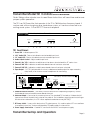
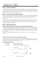
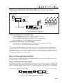
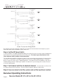
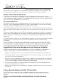
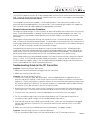
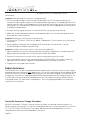
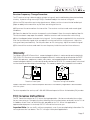
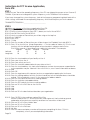
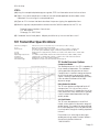
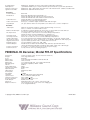
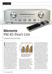
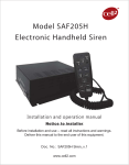
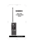
FM Transmitter System
Installation and User Manual
Transmitter Model PPA T21
PPA Receiver Models, R7, R7-4, R7-6, R16, R700
MAN 056
PERSONAL PA BROADCASTING SYSTEM
Installation and User Manual
Contents:
Page:
Transmitter Controls and Features
3
Transmitter Set-Up and Operation
4
Antenna Connection
Power Connection
Audio Connection
Using a Microphone
Connecting to a Sound System
Input Selector Switch
High Pass Filter Switch
RF Power Switch
4
4
4
4
5
6
6
6
Receiver Instructions
7
Battery Information
8
Receiver Management
8
Using a Remote Antenna
9
Troubleshooting
9
Radio Interference Problems
10
Warranty
11
License Instructions
12
Audio Processor Options
13
Specifications
14
Transmitter Model T21 Controls and Features:
Note: Taking a few minutes now to read these instructions will save time and ensure
proper system operation.
The T21 is an FM Transmitter that operates in the 72 to 76MHz business frequency band. It
can be used with a microphone as a stand-alone system, or it can be connected to an
existing sound system. A Part 90 FCC license is required.
FM Auditory AssistanceTransmitter
Power
Audio Level
Ok
1
2
Hi
Transmit Status
+
Adjust
3
Williams Sound
On
4
5
WB
Tape Out/Phones
NB
6
7
8
T21 Front Panel:
1. Power LED - Indicates power ON.
2. “OK” Audio LED - Flashes to indicate nominal audio input level.
3. “HI” Audio LED - Flashes to indicate excessive audio input level.
4. Audio Adjust Control - Adjusts audio input level.
5. Transmit “On” LED - Indicates a valid channel has been selected and the RF carrier is on.
6. Transmit “WB” LED - Indicates a valid wide-band channel has been selected.
7. Transmit “NB” LED - Indicates a valid narrow-band channel has been selected.
8. Tape Output - 1/4” TRS jack provides line-level, unbalanced audio output for tape recorders,
relay feeds, or a stereo or mono headphone for monitoring.
T21 Rear Panel:
Balanced Audio Input
IN 2
IN 3
COM IN 1
Auditory AssistanceTransmitter
1. Audio
Input Jack - Concentric
XLR/
phone plug jack forFM
balanced
and unbalanced
Mic/Line/70V audio inputs. Provides simplex
power for condenser mics.
Unbalanced
Audio Inputs
Antenna
2. Audio Inputs - Screw terminals accept 3 unbalanced, line-level inputs. All inputs are actively
Channel
mixed.
Hi-Pass Filter
RF Power
Select
0
1
Mic
70V 20 Hz
725 Hz
-12dB
Max
Power: 24 VAC, 60 Hz, 10VA
3. Input Level Selector - 3-way
switch
jack
only.
175 Hzselects Mic/Line/70V input level
-6dBfor concentric
Line
Use with TFP 016 Power
Supply
1st
2nd
75 Ohm
Made in USA
Digit
Digit
Williams Sound Corp.
4. High-Pass Filter - 3-way switch provides low-frequency roll-off to reduce system noise and equalize
frequency 1
response
2 for hard
3 of hearing
4 listeners. 5
6
7
8
5. Channel Selector Switches - Two rotary switches determine the operating frequency. Selects
8 wide-band channels and 68 narrow-band channels.
6. Antenna Output - Connector for remote antenna. The standard T21 includes a “rubber duckie”
type antenna that threads into the top of the cabinet. For installations requiring rack mounting or
remote antenna locations, the T21 has an optional coaxial antenna (ANT 005).
7. RF Power Switch - 3-way switch determines RF output power. It is used to reduce RF hum and buzz
in amplifiers/mixers/etc. that are disturbed by RF produced by the transmitter.
8. Power Supply Connection - Coaxial DC connector for 24VAC remote power supply.
Transmitter Set-Up and Operation:
Page 3
Step 1. Install the Antenna
The "rubber duckie" whip antenna fits into the hole on top of the transmitter and threads onto a
mounting stud inside. Guide the antenna onto the stud and turn it clockwise to tighten. Do not use
excessive force to tighten the antenna. It only needs to be finger-tight. See page 9 for instructions
on using the Transmitter with a remote antenna.
Step 2. Connect the Transmitter to Power
The T21 is supplied with a wall transformer power supply (TFP 016). Connect the power cord plug to
the "Power" connector on the rear panel of the T21. Then plug the transformer into a 120 Volt, 60 Hz
wall outlet. The indicator light on the front panel of the T21 should glow when the power is
connected.
There is no on/off switch. Due to low energy consumption, the T21 is designed to run continuously.
The wall transformer can be plugged into a switched outlet that turns on when the other sound
equipment is turned on. If turning the T21 on creates a hum or buzz in the sound system, see the
Troubleshooting section on page 9.
Step 3. Audio Connections
If you will be using the T21 with a microphone as a stand-alone system:
Any professional low-impedance microphone may be used with the T21. Plug the microphone into
the concentric jack (“Balanced Audio Input”) on the rear panel of the T21. The T21 supplies positive
DC voltage to power condenser microphones per DIN45596. Make sure the input selector switch is
in the MIC position. Talking into the microphone should cause the audio indicator light to flash on
the front panel.
If you use both the Microphone input and the Audio Input on the T21, the signals will be mixed
together.
If you will be using the T21 with an existing sound system:
Refer to the Overall System Diagram, above. The T21 has been designed to accept virtually any
type of audio input, with up to four different input signals actively mixed together. Following are the
best sources for an audio signal from the sound system:
Desirable Signal Sources:
1st Choice:
2nd Choice:
3rd Choice:
Page 4
TAPE OUT or LINE OUT Jack
BOOSTER or BRIDGING Jack
Speaker Terminal, or Speaker transformer tap
Microphone Wiring Detail
Following are the input connection options for the T21 Transmitter:
Microphones
Sound System Amplifier
Loudspeakers
Balanced Audio Input
COM
IN 1
IN 2
IN 3
FM Auditory AssistanceTransmitter
Unbalanced
Audio Inputs
Antenna
Channel
Line-Level Output
Select
Hi-Pass Filter
70V 20 Hz
Mic
Line
0
RF Power
1
725 Hz
175 Hz
Made in USA
Max
-12dB
1st
Digit
FM Pocket Receivers
with Earphones
2nd
Digit
75 Ohm
-6dB
Power: 24 VAC, 60 Hz, 10VA
Use with TFP 016 Power Supply
Williams Sound Corp.
T21 Transmitter
Overall System Diagram
“Balanced Audio Input” Concentric Jack:
Accepts balanced XLR or TRS 1/4” Mic-Level or Line-Level Inputs
Accepts unbalanced Mic-Level or Line-Level Inputs
Accepts unbalanced Speaker-Level Inputs (25V, 70V speaker line)
See the diagram on the next page for connection details.
“Unbalanced Audio Input” Screw Terminals:
Accepts one to three unbalanced line-level signals, which are actively mixed.
The three inputs share a common ground connection.
Use the audio cable and adapter supplied to connect the T21 "Audio In" jack to an appropriate
audio output jack on the sound system mixer or amplifier. If your amplifier or mixer does not have
RCA-type connectors, you can obtain adapters from your Williams Sound Authorized Dealer or a
local radio parts store. If the TAPE OUT jack is already in use, a Y-Cord can be used to connect the
T21 and a second device to the same jack.
Step 4. Set the Input Selector Switch
If you are using the combination XLR/phone plug input jack, make sure the selector switch is set in
the proper position as shown above.
Step 5. Set the Hi-Pass Filter Switch
The High-Pass Filter switch is used to reduce low frequencies. It is normally used in the middle (175Hz)
position to provide high frequency emphasis that improves speech understanding. If the program
content is primarily musical, it can be used in the left (20Hz) position. The right position (725Hz) may
From Sound System Line Output
RCA to RCA Cable
To T21 Concentric Jack
RCA to 1/4" Adapter
Using the Audio Cable Supplied with the System
Page 5
Audio Connection Wiring Detail
be used for further low frequency reduction, or it may be used to reduce low frequency system
noise due to pick up of ventilation system noise, etc.
Step 6. Set the RF Power Switch
In some situations, the radio signal produced by the transmitter can enter other types of equipment
and create a hum or buzzing sound in the sound system. This is due to poor RF protection in the
other equipment, NOT a problem with the transmitter.
The normal switch position is MAX power (right). If you encounter a hum or buzz in the sound system
when the T21 Transmitter is turned on, move the switch to the -6dB (middle position). If the buzz
persists, move the switch to the -12dB (left) position. If this does not solve the problem, refer to the
Troubleshooting Section. Reducing the power will reduce the system range, but usually still covers
the entire seating area.
Step 7. Set channel switches to desired channel.
The transmitter must be set to
the same channel as the receivers. See the channel chart on top of the transmitter.
Step 8. Use a receiver to test the system and set the input level control.
Receiver Operating Instructions:
Receiver Models R7, R7-4, R7-6, R16, R19, R19-4:
Page 6
Step 1. Battery Installation:
Open the battery compartment by using a coin in the coin slot in the bottom of the receiver. Press
the battery into place, observing proper battery polarity.
Step 2. Plug the earphone or headphone into the earphone jack.
Step 3. Turn the receiver on by rotating the volume control in the direction of the arrow on top of
the case. Turning the knob in the direction of the arrow will increase the volume. Turning the knob
against the arrow will decrease the volume. To avoid draining the battery, make sure the receiver is
turned off when not in use.
Step 4. If you are using the T21 with an existing sound system, make sure the sound system is turned
on. Have someone speak into a microphone while you listen with the receiver and earphone. You
should be able to hear their voice through the receiver.
If you are using the T21 with a microphone, have someone speak into the microphone while you
listen with the receiver and earphone. You should be able to hear their voice through the receiver.
Step 5. The T21 Transmitter has a screwdriver-adjust input level control located on the front panel to
compensate for different input signal levels. Adjust the control so the “OK” audio light flashes with
the signal. It is alright if the “HI” light comes on occasionally. Reduce the signal level by turning the
control counter-clockwise if the “HI” light is on all the time.
If the “OK” light does not come on at all, turn the T21 input level control clockwise to increase the
signal. If the input level control is fully clockwise and the “OK” light still does not come on, you will
need to increase the signal level at its source (mixer or P.A. amplifier). The phone jack monitors the
sound exactly as it is transmitted.
Additional Instructions for Receiver Model PPA R7-4, PPA R7-6:
The R7-4 and R7-6 receivers feature a channel selector knob on top of the receiver. Turn the
selector knob until you hear the desired program.
Additional Instructions for Receiver Model R16:
The R16 Receiver features a microphone input and dual volume controls. The taller knob turns the
receiver on and off and controls the FM signal level. The shorter knob controls the microphone
signal level. By adjusting the two volume controls, you can hear a mixture of the FM signal and
nearby sounds picked up by the microphone. For more information, see the instructions included
with the R16.
Instructions for Monitor Receiver Model R700:
Step 1. Plug the R700 power cord into a 120 VAC, 60 Hz electrical outlet.
Step 2. Attach the antenna to the connector on the rear panel of the R700.
Step 3. Turn power switch on and adjust volume control until you hear the signal from transmitter.
Using An External Antenna with the R700:
The optional ANT 005 Coaxial Antenna may be used with the R700 to extend the reception range.
Using An External Speaker with the R700:
An external loudspeaker may be used with the R700. Connect the + (plus) loudspeaker wire to the
tip connection of a 1/4" mono phone plug. Connect the - (minus) loudspeaker wire to the sleeve
connection of the 1/4" mono phone plug. Insert the plug into the external speaker jack on
Page 7
the rear panel of the R700. This will cut out the built-in speaker and deliver up to 1 Watt of audio
power into an 8 Ohm speaker. The R700 speaker output jack may also be connected to the high
level input of a PA amplifier. See the instructions included with the R700 for more details.
Battery Information for Receivers:
In normal use, a heavy-duty 9 Volt battery such as the Eveready 216 will last about 10 hours.
Alkaline batteries such as the Eveready 522 will provide about 17 hours of use. If the sound becomes
weak or distorted, replace the battery. The indicator light may still be on, even with a battery that is
weak. Do not leave dead batteries in the receivers.
Rechargeable Batteries:
The receivers can also use a rechargeable battery. We recommend only the 7-cell, 8.4 Volt types
(BAT 003). A fully-charged battery (Williams BAT 003) will provide about 5 hours of use per charge.
The battery may be recharged without removing it from the receiver.
The BAT 005 Single Charger has a cord that plugs into the receiver "EAR" jack to charge the battery.
The CHG 1269A Multiple Charger can charge 12 receivers simultaneously through the receiver "EAR"
jacks.
The receiver should always be turned OFF while charging. It takes about 14 hours to fully charge the
battery. To ensure long battery life, the battery should be completely drained before recharging.
Using the battery for short periods of time (less than 1 hour) followed by charging will result in short
battery life.
If the BAT 005 Single Charger or CHG 1269A Multiple Charger is used, receivers can be left charging
continuously when not in use. See the instructions included with the CHG 1269A for more
information.
DO NOT ATTEMPT TO RECHARGE DISPOSABLE BATTERIES! AVOID SHORTING THE PLUS AND MINUS
BATTERY TERMINALS TOGETHER WITH METAL OBJECTS. BATTERY DAMAGE AND BURNS CAN RESULT!
DO NOT MIX RECHARGEABLE BATTERIES AND CHARGERS FROM DIFFERENT MANUFACTURERS.
Suggestions for Receiver Management and Earphone Sanitation:
Different types of facilities use different approaches for receiver management and earphone
sanitation. Following are some alternatives that other customers have used successfully:
1. Regular users purchase their own receiver and take care of their own batteries and earphone.
2. Some facilities label the receiver and earphone with the names of regular users so each person
uses their own receiver and earphone.
3. Ushers issue receivers to people who request them. Earphones are sanitized after use. Foam ear
cushions can be replaced or washed with a mild detergent, rinsed thoroughly and air-dried. The
EAR 022 Surround Earphone can be sanitized with an alcohol pad.
4. The receivers are stored in a multiple compartment storage case with a credit card or driver's
license left as collateral for the receiver.
5. Regular users purchase their own earphone or headphone and bring them to use with receivers
at the facility
Using a Remote Antenna with the T21 Transmitter:
The ANT 005 remote Coaxial Antenna is available for applications requiring rack-mounted
transmitters, or for use in facilities where a remote antenna is needed for maximum operating
distance.
DO NOT CUT OR ALTER THE ANTENNA CABLE BEFORE READING THE INSTRUCTIONS BELOW!
Page 8
The ANT 005 Coaxial Antenna is a 15 foot coaxial cable with an 80-inch antenna built onto the other
end. The last 80 inches of the antenna is the active element, which is covered by nylon braid. The
active element should never be altered.
The remainder of the antenna cable is RG-59 coax feedline. If you have excess cable, cut the
excess off and install appropriate in-line connectors. If you need a longer feedline, the cable can
be cut and an extension cable added with appropriate connectors.
Remote Antenna Location Guidelines:
For maximum signal strength, it is best to select an antenna location somewhere within the listening
area. The preferred location is towards the front of the listening area and above the seats. The
active element (nylon braid covered portion) must be kept straight, not coiled, in a vertical
orientation.
Radio signals will generally pass through non-metal structures. The antenna can be mounted on a
wall, in a corner, or behind a wooden beam. It may also be hung vertically from the ceiling, with a
small weight attached to the end to make it hang freely. If you need to run the feedline through a
wall, a 1/2" hole is necessary to pass any connectors through.
Avoid placing the antenna on steel beams or near structural steel elements. Metal plaster lath,
metal studs, ductwork, and foil-backed insulation can absorb radio energy, greatly reducing the
range of the system. DO NOT put the antenna element inside a metal conduit. The feedline may
be routed through metal conduit, but NOT with microphone cables or AC power wiring.
Nylon clamps and screws are provided to attach the Coax Antenna to a wall. Locate the clamps
every 3 - 4 feet. DO NOT bend the cable sharply at any point. Allow at least a 3" radius for turns.
DO NOT staple the cable in place. Use the cable clamps provided or hang the antenna from the
excess nylon braid at the end of the antenna element.
Troubleshooting Guide for the T21 Transmitter:
Symptom: Transmitter "Power" light not on.
1. Make sure the wall transformer is plugged into the transmitter.
2. Make sure the electrical outlet is on.
Symptom: No sound through receivers.
1. If some of the receivers work, but others don't, check for bad batteries or earphones on the
receivers that aren't working. Check to see that the receiver frequency matches the transmitter
frequency. Check the frequency selector switches on the transmitter and read the frequency on
the chart on top of the Transmitter. The receiver frequency is indicated inside the back cover of
the receiver. If they do not match, see the Tuning Instructions.
2. If none of the receivers work, check to see if the power is connected to the transmitter and the
"Power" light is on. Check to see if the transmitter and receivers are set on the same frequency.
3. Check to see if the transmitter is connected properly to the sound system. See page 5.
4. Turn the screwdriver-adjust input level control located on the T21 front panel clockwise to
increase the input signal strength until the audio indicator light flashes.
5. If you are not using an input signal from a sound system, make sure the microphone is plugged
into the "Mic" jack on the rear of the T21 transmitter and the input selector switch is in the MIC
(left) position.
6. Make sure the antenna is installed and connected properly. See pages 4 and 9.
Symptom: Sound through receivers is loud, but distorted.
1. Turn the screwdriver-adjust input level control located on the T21 front panel counter-
Page 9
clockwise to decrease the input signal strength. Make sure the “HI” audio light is not on
continuously.
Symptom: Sound through the receivers is weak and noisy.
1. Turn the screwdriver-adjust input level control located on the T21 front panel clockwise to
increase the input signal strength until the audio indicator light flashes. The audio fed into the T21
may be noisy or weak. Use a headphone in the Phones jack on the front of the T21 to listen to the
input signal. If it is weak and noisy from the phones jack, turn up the appropriate mixer control or
try a different audio source.
2. Increase the input signal level from the sound system by turning up a mixer control.
3. Make sure a valid wide-band channel is selected and make sure the transmitter and receivers
are tuned to the same channel.
Symptom: Buzzing or humming noise in sound system.
1. Try moving the “RF Power” switch to the -6dB or -12dB position. This will reduce the system range
somewhat.
2. Some amplifiers and mixers are susceptible to RF pick-up from the transmitter. Call your
Authorized Dealer or Williams Sound for help.
Symptom: Scratchy noise when receiver volume control is adjusted.
1. Open the back of the receiver case by opening the battery compartment. Keep lifting on the
battery door and the back of the receiver case will open like a book.
2. Remove the screw from the center of the volume control and remove the knob.
3. Lift the clear plastic cover on the control and spray GC SPRA-KLEEN, LPS Contact Cleaner, or
equivalent into the control. Replace the knob and rotate the control several time.
4. Replace the screw and close the case.
Radio Interference:
The PERSONAL PA is usually not disturbed by other radio services, however there is no such thing as
a clear or exclusive channel for ANY radio service. One of the unique features of the Williams Sound
PERSONAL PA System is that the operating frequency can easily be changed in the field to avoid
interference. There are 10 wide-band and 50 narrow-band frequencies for hearing assistance use.
The PERSONAL PA can be quickly changed to any of these frequencies by your Williams Sound
Authorized Dealer. The Transmitter is changed first. Then the signal produced by the Transmitter is
used to tune the receivers.
Transmitter Frequency Change Procedure:
(1) Set the two rotary “Channel” selector switches to match the desired channel listed on the
chart on top of the transmitter. One of the 8 wide-band channels must be selected for use with the
R7, R7-4, R7-6, R700,or R16 Receivers. The narrow-band channels are available for use with a
narrowband receiver that will be available in the future.
Page 10
Receiver Frequency Change Procedure:
The R7 receiver tuning is determined by a single tuning coil, and is stabilized by phase-locked-loop
circuitry. A plastic tuning wrench (PLT 005) is needed to adjust the receiver tuning coil.
(1) Use the PPA transmitter as a tuning signal source. Make sure there is some kind of audio input
(tape or radio) to the transmitter so you have something to listen to.
(2) Disconnect the antenna from the transmitter. The receiver must be tuned under weak signal
conditions.
(3) Open the back of the receiver to expose the circuit board. Open the receiver battery flap first.
The receiver back snaps open like a book. Hold the receiver near the transmitter while tuning.
(4) Use the diagram below to locate the tuning coil. Use the earphone supplied with the receiver to
listen for the transmitter signal while you adjust the tuning coil with the tuning wrench. Adjust the
tuning coil slowly and carefully. Do not press down on the tuning slug. Adjust for maximum signal.
(5) Re-tune all the receivers and mark the new frequency inside the case for future reference.
Warranty
The Williams Sound PPA Transmitter is warranted against defects in workmanship and materials for
FIVE YEARS. PPA Receivers are warranted against defects in workmanship and materials for THREE
YEARS. Microphones, earphones, cables, carry cases, rechargeable batteries and chargers are
warranted against defects in workmanship and materials for 90 DAYS. This warranty does not extend
to intentional or accidental physical damage. This warranty applies only to products returned to
Tuning Coil
Receiver Case Open
Receiver Tuning Coil Location
Williams Sound for service. Please complete and return the Warranty Registration Card included
with the system.
To return a product for service, call 1-800-843-3544 and request a Return Authorization (RA) number.
FCC License Instructions:
The T21 Transmitter requires an FCC license for legal operation. We have enclosed a license form
for your convenience. Complete the form, following the instructions below, and mail it to the FCC at
the address listed. There is a $80.00 filing fee, payable to the FCC. When the application is
approved and payment is received, the FCC will mail the license to you.
Important Note: Be sure to fill in all items completely, even if you are duplicating information. Do
not use phrases like "see above." The FCC will reject incomplete applications.
Page 11
Instructions for FCC License Application,
Form 574:
STEP 1:
Determine your Transmitter operating frequency. Your T21 was shipped to you pre-set on Channel E,
72.9MHz. If you have not changed the system frequency, write 72.9MHz on the line below.
If you have changed the system frequency, look at the frequency-programming label. Look at the
switch settings and read the corresponding frequency. Write that frequency on the line below.
TRANSMITTER FREQUENCY:______________________________
STEP 2:
(A) Make a photocopy of the license application Form 574.
(B) Using a pencil, fill in the photocopied form as follows:
BOX 1: Enter the system frequency from STEP 1, above, on the first line of BOX 1.
BOX 2: Enter "MO" on the first line of BOX 2.
BOX 3: Enter the number of Transmitters you will be using on the top line.
BOX 4: Enter "16K0F3E".
BOX 5: Enter ".018".
BOX 6 - 11: Skip
BOX 12: Enter the number of Transmitters you will be using on the "Portable" line inside BOX 12.
BOX 13: Enter ".2" on the first line. (Area of operation ... is .2 miles radius of station A.) Fill in the next
two lines with the latitude and longitude of your location in degrees and minutes.
Fill in 00" for seconds. A local library can supply this information. For example:
Degrees
Minutes
Seconds
Direction
Latitude
42
27
00
N
Longitude
98
15
00
W
BOX 14: Enter the street address of your facility on line A.
BOX 15: Enter your city on line A.
BOX 16: Enter your county on line A.
BOX 17: Enter the two-letter abbreviation for your state on line A.
BOX 18: Enter the street address, city, state, and telephone number where a person responsible for
system operation may be reached. You must fill this in, even if same information as above.
BOX 19: Skip
BOX 20: Enter "IB".
BOX 21: Enter the legal name of the person, business, or organization applying for the license.
BOX 22: Enter the mailing address to which the license and any further correspondence should be
mailed. Fill it incompletely, even if it is the same as the address above.
BOX 23: Enter the city name for the license mailing address.
BOX 24: Enter the two-letter state abbreviation.
BOX 25: Enter the ZIP Code for the license mailing address.
BOX 26: Enter an "X" in the "NO" Box on the first line.
BOX 27: Skip.
BOX 28: Skip.
BOX 29: Skip.
BOX 30: Enter an "X" in the box that best describes your organization.
BOX 31: Enter "90.75A" in the small box marked "Give Rule
Section" inside of BOX 31. Also enter a short, clear statement that includes a general
explanation of your business or activity and how the Transmitter will be used.
BOX 32: Enter an "X" in the "New Station" box.
BOX 33: Enter an "X" in the "Yes" box.
BOX 34: Enter an "X" in the "No" box.
BOX 35, 36: Skip.
BOX 37: Enter the name and phone number of the person completing this form. Fill this in
completely, even if you are duplicating information.
Page 12
BOX 38: Skip.
STEP 3:
(A) Using the completed photocopy as a guide, TYPE the information onto the license form.
(B) Type in the name and phone number of the authorized applicant and the date where
indicated. Be sure to sign the completed form.
(C) Type an "X" in the box that best describes the person signing the application form.
(D) Mail the signed, completed form and a check for $80.00 made out to the FCC to:
Federal Communications Commission
P.O. Box 358220
Pittsburgh, PA 15251-5220
(E) Celebrate! You're finally done. Maybe you'd like to try the new tax forms next?
T21 Transmitter Specifications:
Dimensions, Weight:
Color:
Rack Mount:
Power:
FCC ID:
Operating Frequencies:
Deviation:
Pre-Emphasis:
RF Field Strength:
8.45" (21.5cm) W x 8.18" (20.8cm) D x 1.72" (4.4cm) H, 3lbs. (1.5kg)
Black epoxy paint with white legends
One IEC rack space high, one or two units can be mounted in a single rack
space with optional RPK 005 (single) or RPK 006 (double) Rack Mount Kits
External power supply(TFP 016), 24VAC, 50 or 60Hz, 19VA, 450mA max. current drain
CNMT21
72 - 76MHz, 8 wide-band and 68 narrow-band channels, ±.005% stability, 0-50˚C
± 25kHz max. for wide-band channels, ± 5kHz max for narrow-band channels
Wide-band: 75µsec, narrow-band: 300µsec
20,000µV/m at 30m max. with ANT 005, 120mW typical
T21 Audio Processor Options
Compressor Mode:
The audio processer in the T21 is capable of
three modes of operation. The standard
setting provides compression as shown.
Compression is used for hearing assistance
to limit the dynamic range of the audio
signals. Hearing impaired people generally
have a reduced tolerance for wide
dynamic range.
Noise Reduction Mode:
The T21 can also be configured for for 2:1
compression. This is for use only with a
receiver that has a 2:1 expansion circuit for
noise reduction. Noise reduction is typically
used in narrow-band operation for high
quality audio.
Soft-Limit Mode:
The T21 can also operate in a soft-limit
mode, which allows full dynamic range of
audio signals. This mode may be preferred
for musical programs, but may provide too
much dynamic range for hearing impaired
listeners.
For assistance in selecting an alternate
audio processing mode, contact Williams
Sound technical assistance at
1-800-328-6190.
Page 13
Nominal Range:
AGC Options:
Frequency Response:
Signal to Noise Ratio:
Front Panel:
Power Indicator:
RF Indicators:
Audio Indicators:
Audio Level Control:
Tape Output:
Rear Panel:
Audio Inputs:
Balanced Audio Input:
Mic Input Levels:
Line Input Levels:
70 Volt Input Levels:
Unbal. Audio Inputs:
Input Selector Switch:
High-Pass Filter Switch:
RF Output Switch:
Antenna Outputs:
Power Connections:
Channel Selector:
Wide-band: 300-500ft. (91-152m), Narrow-band: 800-1200 ft. (244-366m)
(1)standard variable slope compressor/limiter (2)Noise Reduction (3)Soft Limit (4)Hard Limit
Wide-band: 30Hz - 15kHz ±3dB, .25% Max. THD Narrow-band: 30 Hz - 5,000 Hz, .25% Max. THD
Wide-band: 60dB with PPA R7 Receiver
Green LED
Green LED "On" indicates transmitter RF is on
Amber LED "WB" indicates wide-band channel selected
Amber LED "NB" indicates narrow-band channel selected
Amber LED "Ok" for nominal input signal level
Red LED "Hi" for excessive input signal level
Rotary pot, screwdriver adjust, used with audio indicator lights
1/4” jack, 600mV, 100Ω source impedance, also drives mono or stereo headphone
All inputs are actively mixed into a single signal, allowing use of mono,
stereo, 3 channel or 4 channel audio sources
Combination 3-pin female XLR/1/4” stereo jack, accepts balanced or unbalanced
microphone and line level inputs, 25V or 70V audio input
Lo-Z, 100µV min. to 50mV max. 1mV nominal, 3kΩ input impedance
Supplies simplex power 20V (DIN45596) for condenser mics
21mV min. to 10V max., 212mV nominal, 100KΩ input impedance
216mV min. to 100V max., 2.16V nominal, 100KΩ input impedance
Four screw terminals, three unbalanced line-level inputs, one ground, actively mixed
3-position slide-type , selects: mic/line/70V on combination XLR/Phone audio input jack
3-position slide-type, 20Hz, 175Hz, or 725Hz, 6dB/octave roll-off
3-position slide-type, Full power, -6dB, -12dB
Thread Mount for "rubber duckie" flexible whip antenna, optional hard-wired
75Ω Coaxial Antenna (ANT 005) uses RG-59 cable, 400ft. (140m) max. cable length
2-conductor, concentric jack, 2.1mm for TFP 016 power supply,
2 rotary switches set the operating frequency
PERSONAL PA Receiver, Model PPA R7 Specifications
Dimensions:
Weight:
Color:
Battery Type:
Battery Drain:
Battery Life:
Operating Freq:
FCC ID:
Intermediate Freq:
Signal-to-Noise Ratio:
Input Overload:
FM Deviation:
De-Emphasis:
AFC Range:
Sensitivity:
Squelch Level:
Frequency Response:
Receiver Antenna:
Audio Output:
Earphone:
Output Connector:
3-5/8"L x 2-3/8"W x 7/8" H (92.1mm x 60.3mm x 22.2mm)
3.2oz (90g) with battery
Burgundy
9 Volt, Eveready 522 Alkaline or BAT 003 Ni-Cad
14mA, nominal
17 hrs with Eveready 522, 3hrs/charge with BAT 003
Pre-Tuned, Adjustable, 72MHz - 76MHz
CNM R7
70kHz
60dB at 10uV
20mV
Wide-band, 75KHz
75uS
+ 300kHz
2uV at 12dB Sinad (squelch defeated)
10uV for minimum 60 dB S/N ratio
100 to 10KHz, + 3 dB
Integral with earphone cord
250mW, max. at 16Ω
Earbud-type with foam cushion, 3.5mm plug, 16Ω
3.5mm mini phone jack, also serves as a charging jack
for rechargeable battery
Copyright 1995, Williams Sound Corp.
MAN 056A