1
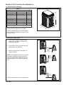
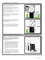
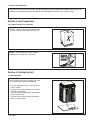
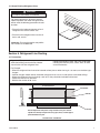
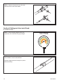
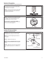
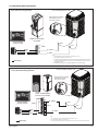
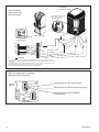
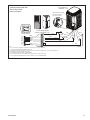
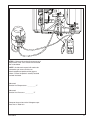
18-BC53D2-6 Installer’s Guide Air Conditioner/Heat Pumps 4TTZ0/4TWZ0 with ComfortLinkTM II and Charge AssistTM ALL phases of this installation must comply with NATIONAL, STATE AND LOCAL CODES IMPORTANT — This Document is customer property and is to remain with this unit. Please return to service information pack upon completion of work. These instructions do not cover all variations in systems or provide for every possible contingency to be met in connection with the installation. Should further information be desired or should particular problems arise which are not covered sufficiently for the purchaser’s purposes, the matter should be referred to your installing dealer or local distributor. NOTE: The manufacturer recommends installing only approved matched indoor and outdoor systems. All of the manufacture’s split systems are A.H.R.I. rated only with TXV/EEV indoor systems. Some of the benefits of installing approved matched indoor and outdoor split systems are maximum efficiency, optimum performance and the best overall system reliability. Table of Contents Section 1. Safety...................................................................................... 2 Section 2. Unit Location Considerations.............................................. 3 Section 3. Unit Preparation..................................................................... 5 Section 4. Setting the Unit...................................................................... 5 Section 5. Refrigerant Line Considerations.......................................... 6 Section 6. Refrigerant Line Routing...................................................... 7 Section 7. Refrigerant Line Brazing....................................................... 8 Section 8. Refrigerant Line Leak Check.............................................. 10 Section 9. Evacuation............................................................................ 11 Section 10. Service Valves.................................................................... 11 Section 11. Electrical - Low Voltage..................................................... 12 Section 12. Electrical - High Voltage.................................................... 17 Section 13. Start Up............................................................................... 18 Section 14. System Charge Adjustment.............................................. 19 Section 15. Checkout Procedures and Troubleshooting.................... 30 Section 1. Safety ▲! WARNING This information is intended for use by individuals possessing adequate backgrounds of electrical and mechanical experience. Any attempt to repair a central air conditioning product may result in personal injury and/or property damage. The manufacture or seller cannot be responsible for the interpretation of this information, nor can it assume any liability in connection with its use. ▲! WARNING These units use R-410A refrigerant which operates at 50 to 70% higher pressures than R-22. Use only R-410A approved service equipment. Refrigerant cylinders are painted a “Rose” color to indicate the type of refrigerant and may contain a “dip” tube to allow for charging of liquid refrigerant into the system. All R-410A systems use a POE oil that readily absorbs moisture from the atmosphere. To limit this “hygroscopic” action, the system should remain sealed whenever possible. If a system has been open to the atmosphere for more than 4 hours, the compressor oil must be replaced. Never break a vacuum with air and always change the driers when opening the system for component replacement. For specific handling concerns with R-410A and POE oil, reference Retrofit Bulletin SS-APG006-EN and APP-APG011-EN or APP-APG012-EN. ▲! WARNING LIVE ELECTRICAL COMPONENTS! During installation, testing, servicing, and troubleshooting of this product, it may be necessary to work with live electrical components. Failure to follow all electrical safety precautions when exposed to live electrical components could result in death or serious injury. ▲! CAUTION If using existing refrigerant lines make certain that all joints are brazed, not soldered. ! CAUTION ▲ Scroll compressor dome temperatures may be hot. Do not touch the top of compressor; it may cause minor to severe burning. NOTE: It is recommended to install manufacturer approved matched indoor and outdoor systems. NOTE: All approved split systems are AHRI rated with only TXV indoor systems. NOTE: The benefits of installing approved indoor and outdoor split systems are maximum efficiency, optimum performance and the best overall system reliability. ▲! WARNING UNIT CONTAINS R-410A REFRIGERANT! R-410A operating pressures exceed the limit of R-22. Proper service equipment is required. Failure to use proper service tools may result in equipment damage or personal injury. SERVICE USE ONLY R-410A REFRIGERANT AND APPROVED POE COMPRESSOR OIL. ▲! WARNING Extreme caution should be exercised when opening the Liquid Line Service Valve. Turn counterclockwise until the valve stem just touches the rolled edge. No torque is required. Failure to follow this warning will result in abrupt release of system charge and may result in personal injury and /or property damage. 218-BC53D2-6 Section 2. Unit Location Considerations 2.1 Unit Dimensions and Weight Table 2.1 Unit Dimensions and Weight Models H x D x W (in) Weight* (lb) 4TTZ0024A 54 x 34 x 37 335 4TTZ0036B 54 x 34 x 37 335 4TTZ0048A/B 54 x 34 x 37 420 4TTZ0060A 54 x 34 x 37 420 4TWZ0024A 54 x 34 x 37 340 4TWZ0036B 54 x 34 x 37 345 4TWZ0048A/B 54 x 34 x 37 430 4TWZ0060A 54 x 34 x 37 430 * Weight values are estimated (uncrated). When mounting the outdoor unit on a roof, be sure the roof will support the unit’s weight. H W D Properly selected isolation is recommended to alleviate sound or vibration transmission to the building structure. 2.2 Refrigerant Piping Limits 1. The maximum length of refrigerant lines from outdoor to indoor unit should NOT exceed sixty (60) feet. 2. The maximum vertical change should not exceed twenty five (25) feet*. 3. Service valve connection diameters are shown in Table 5.1. NOTE: For line lengths greater than sixty (60) feet, Refer to Refrigerant Piping Application Guide, SS-APG006-EN or Refrigerant Piping Software Program, 32-3312-03 (or latest revision). Standard Line Set 60’ Max Line Length * 35’ Max Line Length 25’ Max Line Lift * 25’ Max Line Lift 35’ Max Line Length * Restricted to maximum vertical change of 25 ft. 18-BC53D2-6 3 2.3 Suggested Locations for Best Reliability Ensure the top discharge area is unrestricted for at least five (5) feet above the unit. Avoid Install Near Bedrooms Three (3) feet clearance must be provided in front of the control box (access panels) and any other side requiring service. Do not locate close to bedrooms as operational sounds may be objectionable. Min 5’ Unrestricted Min. 12” to Shrubbery Avoid locations such as near windows where condensation and freezing defrost vapor can annoy a customer. Min 3’ Unrestricted Access Panel Position the outdoor unit a minimum of 12” from any wall or surrounding shrubbery to ensure adequate airflow. Outdoor unit location must be far enough away from any structure to prevent excess roof runoff water or icicles from falling directly on the unit. Min. 12” to Shrubbery Min. 12” to Wall 2.4 Cold Climate Considerations (Heat Pump only) NOTE: It is recommended that these precautions be taken for units being installed in areas where snow accumulation and prolonged below freezing temperatures occur. • Units should be elevated 3-12 inches above the pad or rooftop, depending on local weather. This additional height will allow drainage of snow and ice melted during defrost cycle prior to its refreezing. Ensure that drain holes in unit base pan are not obstructed preventing draining of defrost water. • If possible, avoid locations that are likely to accumulate snow drifts. If not possible, a snow drift barrier should be installed around the unit to prevent a build-up of snow on the sides of the unit. Min. 12” Snow Barrier Snow Legs 3-12” Elevation Pad 418-BC53D2-6 2.5 Coastal Considerations If installed within one mile of salt water, including seacoasts and inland waterways, models without factory supplied Seacoast Salt Shields require the addition of BAYSEAC001 (Seacoast Kit) at installation time. Section 3. Unit Preparation 3.1 Prepare The Unit For Installation STEP 1 - Check for damage and report promptly to the carrier any damage found to the unit. STEP 2 - To remove the unit from the pallet, remove tabs by cutting with a sharp tool. Section 4. Setting the Unit 4.1 Pad Installation When installing the unit on a support pad, such as a concrete slab, consider the following: • The pad should be at least 1” larger than the unit on all sides. • The pad must be separate from any structure. • The pad must be level. • The pad should be high enough above grade to allow for drainage. • The pad location must comply with National, State, and Local codes. 18-BC53D2-6 5 Section 5. Refrigerant Line Considerations 5.1 Refrigerant Line and Service Valve Connection Sizes Table 5.1 Line Sizes Service Valve Connection Sizes Model Vapor Line Liquid Line Vapor Line Connection Liquid Line Connection 4TTZ0024A 3/4 3/8 5/8 3/8 4TTZ0036B 3/4 3/8 3/4 3/8 4TTZ0048A/B 7/8 3/8 3/4 3/8 4TTZ0060A 7/8 3/8 3/4 3/8 4TWZ0024A 5/8 3/8 5/8 3/8 4TWZ0036B 3/4 3/8 3/4 3/8 4TWZ0048A/B 3/4 3/8 3/4 3/8 4TWZ0060A 3/4 3/8 3/4 3/8 5.2 Factory Charge Trane outdoor condensing units are factory charged with the system charge required for the outdoor condensing unit, fifteen (15) feet of tested connecting line, and the smallest indoor evaporative coil match. See unit nameplate. If connecting line length exceeds fifteen (15) feet and/or a larger indoor evaporative coil is installed, then final refrigerant charge adjustment is necessary. Use Charge Assist™ or the Manual Charging procedure found in the outdoor unit Service Facts. Charge level can always be verified with the Refrigerant Charging Chart found in the Service Facts. 5.3 Required Refrigerant Line Length Determine required line length and lift. You will need this later in STEP 2 of Section 14. Total Line Length = __________ Ft. Line Length Total Vertical Change (lift) = __________ Ft. 5.4 Refrigerant Line Insulation Important: The Vapor Line must always be insulated. DO NOT allow the Liquid Line and Vapor Line to come in direct (metal to metal) contact. Liquid Line Vapor Line Insulation 618-BC53D2-6 5.5 Reuse Existing Refrigerant Lines ! CAUTION ▲ If using existing refrigerant lines make certain that all joints are brazed, not soldered. For retrofit applications, where the existing indoor evaporator coil and/or refrigerant lines will be used, the following precautions should be taken: • Ensure that the indoor evaporator coil and refrigerant lines are the correct size. • Ensure that the refrigerant lines are free of leaks, acid, and oil. Important: For more information see publication number SS-APG006-EN. Section 6. Refrigerant Line Routing 6.1 Precautions Important: Take precautions to prevent noise within the building structure due to vibration transmission from the refrigerant lines. Comply with National, State, and Local Codes when isolating line sets from joists, rafters, walls, or other structural elements. For Example: • When the refrigerant lines have to be fastened to floor joists or other framing in a structure, use isolation type hangers. • Isolation hangers should also be used when refrigerant lines are run in stud spaces or enclosed ceilings. • Where the refrigerant lines run through a wall or sill, they should be insulated and isolated. • Isolate the lines from all ductwork. •Minimize the number of 90º turns. 8 Feet Maximum Joist/Rafter Isolator Side View 8 Feet Maximum Line Set Secure Vapor line from joists using isolators every 8 ft. Secure Liquid Line directly to Vapor line using tape, wire, or other appropriate method every 8 ft. Isolation From Joist/Rafter 18-BC53D2-6 7 8 Feet Maximum Wall Isolator 8 Feet Maximum Side View Line Set Secure Vapor Line using isolators every 8 ft. Secure Liquid Line directly to Vapor Line using tape, wire, or other appropriate method every 8 ft. Isolation In Wall Spaces Wall Sealant Ductwork Insulation Vapor Line Isolator Line Set Isolation Through Wall DO NOT hang line sets from ductwork Section 7. Refrigerant Line Brazing 7.1 Braze The Refrigerant Lines STEP 1 - Remove caps or plugs. Use a deburring tool to debur the pipe ends. Clean both internal and external surfaces of the tubing using an emery cloth. 818-BC53D2-6 STEP 2 - Remove the pressure tap cap and valve cores from both service valves. STEP 3 - Purge the refrigerant lines and indoor coil with dry nitrogen. STEP 4 - Wrap a wet rag around the valve body to avoid heat damage and continue the dry nitrogen purge. Braze the refrigerant lines to the service valves. Continue the dry nitrogen purge. Do not remove the wet rag until all brazing is completed. Important: Remove the wet rag before stopping the dry nitrogen purge. NOTE: Precautions should be taken to avoid heat damage to basepan during brazing. It is recommended to keep the flame directly off of the basepan. 18-BC53D2-6 9 STEP 5 - Replace the pressure tap valve cores after the service valves have cooled. Section 8. Refrigerant Line Leak Check 8.1 Check For Leaks STEP 1 - Pressurize the refrigerant lines and evaporator coil to 150 PSIG using dry nitrogen. 150 PSIG STEP 2 - Check for leaks by using a soapy solution or bubbles at each brazed location. Remove nitrogen pressure and repair any leaks before continuing. 1018-BC53D2-6 Section 9. Evacuation 9.1 Evacuate the Refrigerant Lines and Indoor Coil Important: Do not open the service valves until the refrigerant lines and indoor coil leak check and evacuation are complete. 0350 Microns STEP 1 - Evacuate until the micron gauge reads no higher than 350 microns, then close off the valve to the vacuum pump. ON OFF STEP 2 - Observe the micron gauge. Evacuation is complete if the micron gauge does not rise above 500 microns in one (1) minute. 1 MIN. Once evacuation is complete blank off the vacuum pump and micron gauge, and close the valves on the manifold gauge set. Section 10. Service Valves 10.1 Open the Gas Service Valve Important: Leak check and evacuation must be completed before opening the service valves. CAP NOTE: Do not vent refrigerant gases into the atmosphere VALVE STEM STEP 1 - Remove valve stem cap. STEP 2 - Using an adjustable wrench, turn valve stem 1/4 turn counterclockwise to the fully open position. STEP 3 - Replace the valve stem cap to prevent leaks. Tighten finger tight plus an additional 1/6 turn. 1/4 TURN ONLY COUNTERCLOCKWISE FOR FULL OPEN POSITION UNIT SIDE OF VALVE PRESSURE TAP PORT GAS LINE CONNECTION 18-BC53D2-6 11 10.1 Open the Liquid Service Valve ▲! WARNING Extreme caution should be exercised when opening the Liquid Line Service Valve. Turn counterclockwise until the valve stem just touches the rolled edge. No torque is required. Failure to follow this warning will result in abrupt release of system charge and may result in personal injury and /or property damage. Cap Unit Side of Service Valve 3/16” Hex Wrench Rolled Edge to Captivate Stem Important: Leak check and evacuation must be completed before opening the service valves. Hex Headed Valve System STEP 1 - Remove service valve cap. STEP 2 - Fully insert 3/16” hex wrench into the stem and back out counterclockwise until valve stem just touches the rolled edge (approximately five (5) turns.) Service Port STEP 3 - Replace the valve cap to prevent leaks. Tighten finger tight plus an additional 1/6 turn. Section 11. Electrical - Low Voltage 11.1 Low Voltage Maximum Wire Length Table 11.1 defines the maximum total length of low voltage wiring from the outdoor unit, to the indoor unit, and to the thermostat. NOTE: The use of color coded low voltage wire is recommended to simplify connections between the outdoor unit, the control, and the indoor unit. NOTE: The maximum total cable length for the entire comfort control communicating system is 500 ft. 18 AWG. Table 11.1 ComfortLinkTM II Control Wiring WIRE SIZE MAX. WIRE LENGTH 18 AWG 250 Ft. 24 VOLTS WIRE SIZE MAX. WIRE LENGTH 18 AWG 150 Ft. 16 AWG 225 Ft. 14 AWG 300 Ft. 1218-BC53D2-6 11.2 Low Voltage Hook-up Diagrams Communicating Outdoor Unit Fully Communicating System Neatly bundle all low voltage wires behind the service valve cover as shown. TAM8 Communicating Air Handler Communicating Comfort Control Brown Y2 Y1 Note 1 O D - Note 2 D R B B - Blue Brown Red Blue Blue Notes: 1. In communicating mode, unused terminals are non-functional. Do not use. 2. “D” is the data line. Installer to select a wire color. 3. If a 3rd party condensate overflow switch is installed, it should be wired in series with R to the thermostat or connected to the External Switch terminals on the AFC. See External Switch wiring section in the air handler Installer’s Guide. 4. For 24 VAC Outdoor equipment, accessory BAYCC24VK01A must be ordered separately. Field wiring Communicating Outdoor Unit Fully Communicating System Neatly bundle all low voltage wires behind the service valve cover as shown. Comm. Variable Speed Furnace or Air Handler Communicating Comfort Control Note 3 Brown Red Blue Field wiring R BK D - Note 2 D Y1 Y2 G Note 1 W1 W2 W3 B - Blue B O Brown Blue Notes: 1. In communicating mode, unused terminals are non-functional. Do not use. 2. “D” is the data line. Installer to select a wire color. 3. To connect optional devices (such as a float switch), wire in series from indoor unit “R” to Comfort Control “R”. 18-BC53D2-6 13 Air Conditioner or Heat Pump - Note 4 TAM7 Air Handler with 24 Volt Control Hook-up Diagram Neatly bundle all low voltage wires behind the service valve cover as shown. Note 5 Black TAM7 Air Handler 24 Volt (X2) Yellow Comfort Control X2 W G Y1 O R B Y2 Yellow/Red W3 * W2 W1 BK G Y2 YI (In) O R B YO (Out) White Green Yellow Orange Red Blue Brown Field wiring W1 - White Orange Red Blue Y2 - Brown O - Orange R - Red B - Blue Y1 - Yellow Note: 1. * For multiple stages of electric heat, jumper W1, W2, and W3 together if comfort control has only one stage of heat. 2. YI and YO connections must be made as shown for freeze protection and internally mounted condensate overflow circuits to work properly. 3. If a 3rd party condensate overflow switch is installed, it should be wired in series between YO and Y to the outdoor unit. 4. Air conditioner models do not use the Black (X2) or Orange wires from the outdoor unit. 5. For non-communicating applications, use 24 volt harness accessory BAYACHP024A. TAM7 Air Handler with 24 Volt Control Hook-up Diagram (Continued) OUTDOOR on HP 1 1 R4 1 2 3 4 5 Control Board AC (System) 2 (Compressor) INDOOR R NET 1 } Cool Off Delay } R6 CFM/Ton U1 C22 Torque D9 L1 C10 C21 C19 C18 C15 C12 R13 R14 Must configure to “ON” for 20 SEER (2 compressors) on R NET 2 R22 1 2 3 4 5 R1 Must configure to “ON” for 20 SEER (2 stages) 2 (Stages) S1 1 Must configure to “OFF” for heat pump. } Capacity (Tons) CFM S2 +12V 1418-BC53D2-6 Air Conditioner or Heat Pump - Note 6 Communicating Indoor Unit with 24 Volt Control Hook-up Diagram Neatly bundle all low voltage wires behind the service valve cover as shown. Comfort Control R Y1 Y2 G W1 X2 B O Red Yellow Brown Green White Blue Orange Comm. Variable Speed Furnace or Air Handler - Note 1 R BK D Yellow Y1 Y2 G W1 W2 W3 B O Note 7 Yellow Black Yellow/Red Brown Notes: 1. See User Interface setup menu for 24 VAC control mode and cooling CFM options. 2. First stage CFM for 4TTZ0 and 4TWZ0 equals 50%. 3. For furnace+heat pump applications, comfort control must be dual fuel capable or use accessory TAYPLUS103A. 4. W3 terminal may not be present on indoor unit. 5. Comfort Control may not have W2 or W3 terminals. 6. Air conditioner models do not use Black (X2) or Orange wires from the outdoor unit. 7. For non-communicating applications, use 24 volt harness accessory BAYACHP024A. 18-BC53D2-6 Orange Red Red Blue (X2) Black Blue Orange 15 FAULT IDENTIFICATION A fault condition is indicated by the fault LED on the control board inside the heat pump control box. In normal operation, the status LED will flash once each second. If the light is flashing more than once per second or not at all, refer to the Service Facts for that unit. FRC_DFT OUTDOOR CONTROL BOARD – PIN IDENTIFICATION TST The demand defrost control measures heat pump outdoor ambient temperature with a sensor located outside the outdoor coil. A second sensor located on the outdoor coil is used to measure the coil temperature. The difference between the ambient and the colder coil temperature is the difference or delta-T measurement. This delta-T measurement is representative of the operating state and relative capacity of the heat pump system. By measuring the change in delta-T, we can determine the need for defrost. The coil sensor also serves to sense outdoor coil temperature for termination of the defrost cycle. TEST_COMMON 11.3 Defrost Control (Heat Pump only) DEFROST CONTROL CHECKOUT Normal operation requires: a. Status LED on board flashing 1 time/second. b. 12 VDC between D & B in communicating mode. PIN IDENTIFICATION c. 24 VAC between R & B in 24V mode. 1. TEST_COMMON (Shorting any of the other pins to this pin causes the function of the other pin to be executed. Leaving this pin open results in the normal mode of operation.) d. Defrost initiation when FRC_DFT pin is shorted to TEST_COMMON pin. If a defrost control problem is suspected, refer to the service information in control box. 2. TST = Test (Shorting TEST_COMMON to this pin speeds up all defrost board timings.) 3. FRC_DFT = Forced Defrost (Short TEST_COMMON to this pin for two [2] seconds to initiate a forced defrost. Remove the short after defrost initiates.) 1618-BC53D2-6 Section 12. Electrical - High Voltage 12.1 High Voltage Power Supply ▲! WARNING LIVE ELECTRICAL COMPONENTS! During installation, testing, servicing, and troubleshooting of this product, it may be necessary to work with live electrical components. Failure to follow all electrical safety precautions when exposed to live electrical components could result in death or serious injury. The high voltage power supply must agree with the equipment nameplate. Power wiring must comply with national, state, and local codes. Follow instructions on unit wiring diagram located on the inside of the control box cover and in the Service Facts document included with the unit. 12.2 High Voltage Disconnect Switch Install a separate disconnect switch at the outdoor unit. For high voltage connections, flexible electrical conduit is recommended whenever vibration transmission may create a noise problem within the structure. 12.3 High Voltage Ground Ground the outdoor unit per national, state, and local code requirements. 18-BC53D2-6 17 Section 13. Start Up 13.1 System Start Up STEP 1 - Ensure Sections 7 through 12 have been completed. STEP 2 - Set System Thermostat to OFF. OFF DONE CANCEL STEP 3 - Turn on disconnect(s) to apply power to the indoor and outdoor units. ON OFF STEP 4 - Wait one (1) hour before starting the unit if compressor crankcase heater accessory is used and the Outdoor Ambient is below 70ºF. 60 MIN. STEP 5 - Set system thermostat to ON. ON DONE CANCEL 1818-BC53D2-6 Section 14. System Charge Adjustment 14.1 Temperature Measurements STEP 1 - Check the outdoor temperatures. Subcooling (in cooling mode) is the only recommended method of charging above 55º F ambient outdoor temperature. See Section 14.2. 120º F See Section 14.2 for Outdoor Temperatures Above 55º F 55º F Outdoor Temp 1 For outdoor temperatures below 55º F, follow the Superheat charging instructions (in heating mode). See Section 14.6. NOTE: It is important to return in the spring or summer to accurately charge the system in the cooling mode with outdoor ambient temperature below 55ºF. See Section 14.6 for Outdoor Temperatures Below 55º F 55º F Outdoor Temp 2 For best results the indoor temperature should be kept between 70º F to 80º F. 80º F 70º F Indoor Temp 14.2 Subcooling Charging in Cooling (Above 55º F Outdoor Temp.) STEP 1 - Use the refrigerant line total length and lift measurements from Section 5.3. Total Line Length = __________ Ft. Vertical Change (Lift) = __________ Ft. LIFT 18-BC53D2-6 19 STEP 2 - Using the total Line Length and Lift measured in STEP 1 and the subcool charging table corrections below, determine the Dip Switch position for your model. SUBCOOL CHARGING TABLE CORRECTIONS FOR LINE LENGTH AND RISE TABLE B REFRIGERANT LINE LIFT (FEET) REFRIGERANT LINE LIFT (FEET) TABLE A All other approved, matched systems. Max Lift 25 20 15 Dip Switch 2-ON 10 0 Dip Switch 1-ON 4TEE3_03 Air Handler Downflow & Horizontal Left Only These matches ONLY 4TXCB003 Coil Downflow & Horizontal Right Only 4TXCC006 Coil Downflow & Horizontal Right Only Max Lift 25 20 15 Dip Switch 3-ON 10 0 10 20 25 30 40 60 80 TOTAL REFRIGERANT LINE LENGTH (FEET) 10 20 25 30 40 60 80 TOTAL REFRIGERANT LINE LENGTH (FEET) SUBCOOL CHARGING TABLE CORRECTIONS FOR LINE LENGTH AND RISE TABLE B REFRIGERANT LINE LIFT (FEET) REFRIGERANT LINE LIFT (FEET) TABLE A All other approved, matched systems. Max Lift 25 20 15 Dip Switch 3-ON 10 0 Dip Switch 2-ON 4TEE3_06 Air Handler 4TXCC008 Coil 4TXCD010 Coil These matches ONLY Max Lift 25 20 15 Dip Switch 1-ON 10 0 10 20 25 30 40 60 80 TOTAL REFRIGERANT LINE LENGTH (FEET) 10 20 25 30 40 60 80 TOTAL REFRIGERANT LINE LENGTH (FEET) All other approved, matched systems. Max Lift 25 20 15 MIDDLE Dip Switch 2-ON 10 0 UPPER Dip Switch 3-ON LOWER Dip Switch 1-ON REFRIGERANT LINE LIFT (FEET) SUBCOOL CHARGING TABLE CORRECTIONS FOR LINE LENGTH AND RISE REFRIGERANT LINE LIFT (FEET) 5-TON HP MODELS ONLY 4-TON HP MODEL ONLY 2-TON HP MODEL ONLY SUBCOOL CHARGING TABLE CORRECTIONS 4TEE3_10 Downflow & Horizontal Left Only Max Lift 25 20 15 Dip Switch 3-ON 10 0 10 20 25 30 40 60 80 TOTAL REFRIGERANT LINE LENGTH (FEET) 10 20 25 30 40 60 80 TOTAL REFRIGERANT LINE LENGTH (FEET) REFRIGERANT LINE LIFT (FEET) 3-TON HP MODELS AND ALL AC MODELS SUBCOOL CHARGING TABLE CORRECTIONS FOR LINE LENGTH AND RISE All approved, matched systems. 25 20 15 10 0 Max Lift UPPER LOWER Dip Switch 2-ON Dip Switch 1-ON 10 Dip Switch 3-ON MIDDLE 20 25 30 40 60 80 TOTAL REFRIGERANT LINE LENGTH (FEET) Dip Switch setting from Subcool Charging Table Corrections = __________ Set Dip Switch on the Charge AssistTM control board. 2018-BC53D2-6 14.3 Determine the charge adjustment procedure Final refrigerant charge adjustment is necessary. Choose the appropriate method below. • • Charge AssistTM procedure in Section 14.4 Manual charging procedure in Section 14.5 14.4 Charge AssistTM Procedure NOTE: Outdoor Temperature (ODT) must be between 55°F and 120°F. See Section 14.1 OUTDOOR CONTROL BOARD – CHARGE ASSIST™ IMPORTANT: Be sure to set Dip Switches on the Outdoor Control Board for Line Length and Lift before entering Charge Assist™ Mode. See Section 14.2 STEP 1 - To enter Charge Assist™ Mode, press the MODE button for at least one (1) second. The on-board LEDs will indicate if the system is capable of continuing. For a detailed description of on-board LEDs and their function, see the Service Facts. The system will take approximately 12-20 minutes to stabilize before the charge can be checked by Charge Assist™. Once the system is stabilized, watch to see which LED turns on next. If the system charge is correct, the “CHARGED” LED will turn on and remain on for one (1) hour. Once charged, the system will exit Charge Assist™ and control will return to the Comfort Control. STEP 2 - If the system charge is low, the “ADD” LED will turn on and stay on up to one (1) hour or until enough refrigerant is added to reach the required system charge level and turn on the “CHARGED” LED. When the “ADD” LED is on, the charging solenoid output will be active. This feature works to automatically control refrigerant flow with BAYCAKT001. CHARGE ASSIST™ PORT STEP 3 - If the system charge is high, the “REC” LED will turn on and the unit will exit Charge Assist™. You must recover refrigerant from the system before re-entering Charge Assist™. For instructions on the Charge Assist™ tool BAYCAKT001, see the Installer’s Guide 18-HH15D1-* (the position of the * denotes the latest revision number). NOTE: Charge Assist™ port is designed for liquid refrigerant charging. 18-BC53D2-6 21 14.5 Manual Charging Procedure in Cooling between 55°F and 120°F OD Ambient NOTE: Outdoor Temperature (ODT) must be between 55°F and 120°F. See Section 14.1 IMPORTANT: Be sure to set Dip Switches on the Outdoor Control Board for Line Length and Lift. Use the corresponding charge chart and dip switch column in Section 14.2 to determine desired liquid pressure when using the manual charging procedure. STEP 1 - Stabilize the system by operating for a minimum of 20 minutes. At startup, or whenever charge is removed or added, the system must be operated for a minimum of 20 minutes to stabilize before accurate measurements can be made. 20 MIN. STEP 2 - Measure the liquid line temperature and pressure at the outdoor unit’s service valve. Measured Liquid Line Temp = __________ º F Liquid Gage Pressure = __________ PSIG 107 °F Dip Switch setting from 14.2 Step 2 __________ 2218-BC53D2-6 Use the liquid line temperature and liquid line gage pressure from Step 2, along with the Dip Switch setting column, to determine the proper Liquid Gage Pressure. STEP 3 - Find the appropriate refrigerant charging chart on the following page for your system type and tonnage. STEP 4 - Locate your liquid line temperature in the left column of the table and the intersecting liquid line gage pressure under the DIPSWITCH selection column. Example: • A 3 ton AC is installed with line length of 30 feet and a line lift of 15 feet. • The Dip Switch setting is 2-ON. • The measured liquid line temperature is 85°F and the Liquid Gage Pressure is 299 PSIG. 3 TON AC R410A REFRIGERANT CHARGING CHART LIQUID GAGE PRESSURE (PSIG) ONLY DIPSWITCH ONLY DIPSWITCH ONLY DIPSWITCH 1 ON 2 ON 3 ON Liquid Temp (°F) 55 60 65 70 75 80 85 90 95 100 105 110 115 120 125 LOWER * MIDDLE UPPER 186 186 190 202 202 206 219 219 222 237 237 240 256 256 260 277 277 280 299 299 302 322 322 325 346 346 350 371 371 375 397 397 402 425 425 430 454 454 460 484 484 491 515 515 523 * Data is based on 10.5° of subcooling at a 95° ambient PRINTED FROM D155861P02 REV 2 Example 299 PSIG is shown as the intersection of the Dip Switch ON column and the 85°F Liquid Temperature row. 18-BC53D2-6 23 2 TON HP R410A REFRIGERANT CHARGING CHART 2 TON AC R410A REFRIGERANT CHARGING CHART LIQUID GAGE PRESSURE (PSIG) ONLY DIPSWITCH ONLY DIPSWITCH ONLY DIPSWITCH 1 ON 2 ON 3 ON LIQUID GAGE PRESSURE (PSIG) 2 Ton AC ONLY DIPSWITCH ONLY DIPSWITCH ONLY DIPSWITCH 1 ON 2 ON 3 ON Liquid Temp (°F) 55 60 65 70 75 80 85 90 95 100 105 110 115 120 125 LOWER * MIDDLE UPPER 2 Ton HP 191 196 197 205 210 212 221 226 227 237 243 244 255 261 263 274 281 283 295 302 305 316 325 328 339 349 352 364 374 378 390 401 406 417 430 435 445 460 465 475 491 497 505 524 530 * Data is based on 10.1° of subcooling at a 95° ambient PRINTED FROM D155861P01 REV 2 3 Ton AC Liquid Temp (°F) 55 60 65 70 75 80 85 90 95 100 105 110 115 120 125 LOWER * MIDDLE UPPER 3 Ton HP Liquid Temp (°F) 55 60 65 70 75 80 85 90 95 100 105 110 115 120 125 LOWER * MIDDLE 4 Ton HP UPPER 5 TON AC R410A REFRIGERANT CHARGING CHART 5 Ton AC Liquid Temp (°F) 55 60 65 70 75 80 85 90 95 100 105 110 115 120 125 LOWER * MIDDLE UPPER 191 197 201 207 213 218 224 231 236 242 249 255 261 268 275 281 289 296 302 310 318 324 333 342 347 356 366 372 381 392 397 407 418 423 434 446 451 462 474 479 491 504 509 521 535 * Data is based on 11.2° of subcooling at a 95° ambient PRINTED FROM D155861P04 REV 2 LIQUID GAGE PRESSURE (PSIG) ONLY DIPSWITCH ONLY DIPSWITCH ONLY DIPSWITCH 1 ON ** 2 ON 3 ON Liquid Temp (°F) 55 60 65 70 75 80 85 90 95 100 105 110 115 120 125 LOWER * MIDDLE UPPER LIQUID GAGE PRESSURE (PSIG) ONLY DIPSWITCH ONLY DIPSWITCH ONLY DIPSWITCH 1 ON 2 ON 3 ON Liquid Temp (°F) 55 60 65 70 75 80 85 90 95 100 105 110 115 120 125 SEE TABLE B ** SEE TABLE A * SEE TABLE A 202 204 206 217 220 223 234 238 240 251 256 259 270 277 280 290 298 301 312 321 325 334 345 349 358 370 375 383 397 403 409 425 432 436 454 462 465 485 494 494 516 527 525 550 562 * Data is based on 15.9° of subcooling at a 95° ambient ** Data is based on 13.5° of subcooling at a 95° ambient ** With AM7 or AM8: Dip switch 1 = 13° of subcooling at 95° ambient PRINTED FROM D155859P03 REV 4 200 203 208 217 221 225 235 239 243 254 258 263 274 279 284 295 301 306 318 323 329 341 347 354 366 372 379 392 398 406 418 426 434 446 454 464 475 483 495 506 514 526 537 545 560 * Data is based on 15.0° of subcooling at a 95° ambient ** With AM7 or AM8: Dip Switch 1 = 13° subcooling at a 95° ambient PRINTED FROM D155861P03 REV 2 LIQUID GAGE PRESSURE (PSIG) ONLY DIPSWITCH ONLY DIPSWITCH ONLY DIPSWITCH 1 ON 2 ON 3 ON SEE TABLE B 4 TON HP R410A REFRIGERANT CHARGING CHART 4 TON AC R410A REFRIGERANT CHARGING CHART 4 Ton AC SEE TABLE A 192 199 210 206 213 227 221 229 245 238 246 264 256 264 284 275 284 306 295 305 329 316 327 354 339 350 380 363 374 407 388 400 435 415 427 465 443 456 497 471 485 529 502 516 563 * Data is based on 9.5° of subcooling at a 95° ambient ** Data is based on 18.0° of subcooling at a 95° ambient PRINTED FROM D155859P01 REV 4 194 195 199 208 210 215 224 227 232 242 246 250 260 265 270 280 286 291 301 308 313 324 331 337 348 356 362 373 382 388 399 409 416 427 438 445 456 467 475 486 498 507 517 531 540 * Data is based on 11.5° of subcooling at a 95° ambient ** With AM7 or AM8: Dip switch 1 = 10° of subcooling at 95° ambient PRINTED FROM D155859P02 REV 4 186 186 190 202 202 206 219 219 222 237 237 240 256 256 260 277 277 280 299 299 302 322 322 325 346 346 350 371 371 375 397 397 402 425 425 430 454 454 460 484 484 491 515 515 523 * Data is based on 10.5° of subcooling at a 95° ambient ** With AM7 or AM8: Dip switch 1 = 11° of subcooling at 95° ambient PRINTED FROM D155861P02 REV 2 LIQUID GAGE PRESSURE (PSIG) ONLY DIPSWITCH ONLY DIPSWITCH ONLY DIPSWITCH 1 ON ** 2 ON 3 ON SEE TABLE A * 3 TON HP R410A REFRIGERANT CHARGING CHART 3 TON AC R410A REFRIGERANT CHARGING CHART LIQUID GAGE PRESSURE (PSIG) ONLY DIPSWITCH ONLY DIPSWITCH ONLY DIPSWITCH 1 ON ** 2 ON 3 ON Liquid Temp (°F) 55 60 65 70 75 80 85 90 95 100 105 110 115 120 125 5 TON HP R410A REFRIGERANT CHARGING CHART 5 Ton HP LIQUID GAGE PRESSURE (PSIG) ONLY DIPSWITCH ONLY DIPSWITCH ONLY DIPSWITCH 1 ON 2 ON 3 ON UPPER & 4TEE3_10 LOWER * MIDDLE DOWNFLOW & HORIZ. Liquid LEFT ** Temp (°F) 55 208 208 210 60 225 225 227 65 242 242 245 70 260 260 264 75 280 280 284 80 300 300 305 85 322 322 327 90 345 345 350 95 369 369 374 100 394 394 400 105 420 420 426 110 447 447 454 115 476 476 483 120 505 505 513 125 536 536 544 * Data is based on 14.8° of subcooling at a 95° ambient ** Data is based on 16.7° of subcooling at a 95° ambient PRINTED FROM D155859P04 REV 4 Note: See page 20 for subcool charging correction tables A and B 24 STEP 5 - Adjust refrigerant level to attain proper gage pressure. Add refrigerant if the Liquid Gage Pressure is lower than the chart value. 1. Connect gages to refrigerant bottle and unit as illustrated. 2. Purge all hoses. 3. Open bottle. 4. Stop adding refrigerant when liquid line temperature and Liquid Gage Pressure matches the charging chart. Recover refrigerant if the Liquid Gage Pressure is higher than the chart value. STEP 6 - Stabilize the system. 1. Wait 20 minutes for the system condition to stabilize between adjustments. 20 MIN. NOTE: When the Liquid Line Temperature and Gage Pressure approximately match the chart, the system is properly charged. 2. Remove gages. 3. Replace service port caps to prevent leaks. Tighten finger tight plus an additional 1/6 turn. STEP 7 - Verify typical performance. (Example only - see Service Facts) PRESSURE CURVES FOR 4TWX5049E1000B 4TEE3F49C1 4TEE3F49C1 Cooling @ 1450 SCFM Refer to System Pressure Curves in the Service Facts to verify typical performance. DISCHARGE PRESSURE (PSIG) 550 Heating @ 1350 SCFM 500 INDOOR ENTERING WET BULB CURVES TOP TO BOTTOM 71, 67, 63 AND 59 DEG F. 500 (2) 450 INDOOR ENTERING DRY BULB CURVES TOP TO BOTTOM 80, 70, AND 60 DEG F. 450 400 400 350 350 (4) (3) 300 300 250 250 (1) 200 40 60 80 200 100 -5 120 5 15 25 35 45 55 25 35 45 55 65 OUTDOOR TEMPERATURE (Degree F) 170 SUCTION PRESSURE (PSIG) 165 160 140 INDOOR ENTERING WET BULB CURVES TOP TO BOTTOM 71, 67, 63 AND 59 DEG F. 150 145 120 110 100 (5) 140 INDOOR ENTERING DRY BULB CURVES TOP TO BOTTOM 80, 70, AND 60 DEG F. 130 (2) 155 (3) 90 135 80 130 70 60 125 50 120 115 40 (1) 110 40 60 80 30 100 120 -5 5 15 65 OUTDOOR TEMPERATURE (Degree F) COOLING PERFORMANCE CAN BE CHECKED WHEN THE OUTDOOR TEMP IS ABOVE 65 DEG F. TO CHECK COOLING PERFORMANCE, SELECT THE PROPER INDOOR CFM, ALLOW PRESSURES TO STABILIZE. MEASURE INDOOR WET BULB TEMPERATURE, OUTDOOR TEMPERATURE, DISCHARGE AND SUCTION PRESSURES. ON THE PLOTS LOCATE OUTDOOR TEMPERATURE (1); LOCATE INDOOR WET BULB (2); FIND INTERSECTION OF OD TEMP. & ID W.B. (3); READ DISCHARGE OR SUCTION PRESSURE IN LEFT COLUMN (4). EXAMPLE: (1) OUTDOOR TEMP. 82 F. (2) INDOOR WET BULB 67 F. (3) AT INTERSECTION (4) DISCHARGE PRESSURE @ 1450 CFM IS 323 PSIG (5) SUCTION PRESSURE @ 1450 CFM IS 140 PSIG ACTUAL: DISCHARGE PRESSURE SHOULD BE +/- 10 PSI OF CHART SUCTION PRESSURE SHOULD BE +/- 3 PSIG OF CHART INTERCONNECTING LINES GAS - 7/8" O.D. LIQUID - 3/8" O.D. DWG.NO. 4TWX5049E1 18-BC53D2-6 25 STEP 8 - Record System Information for reference. Record system pressures and temperatures after charging is complete. Outdoor model number = _________________ Measured Suction Line Temp = __________ º F Measured Outdoor Ambient = __________ º F Liquid Gage Pressure = __________ PSIG Measured Indoor Ambient = __________ º F Suction Gage Pressure = __________ PSIG Measured Liquid Line Temp = __________ º F Dip Switch Selection = _____________ 14.6 Subcooling Charging Below 55º F Outdoor Temp. (In Heating Only) STEP 1 - Check the outdoor temperature. If the ODT is less than 55º F, follow these charging instructions for the heating mode of operation. For temperatures above 55º F, see Section 14.1. NOTE: It is important to return in the spring or summer to accurately charge the system in the cooling mode with outdoor ambient above 55ºF. 80º F 70º F 55º F Outdoor Temp Indoor Temp For best results the indoor temperature should be kept between 70º F and 80º F. See the Indoor Temp illustration. Add system heat if needed. STEP 2 - Stabilize the system by operating in the heating mode for a minimum of 20 minutes. Important: Whenever charge is added or removed, the system must run for a minimum of 20 minutes before accurate measurements can be made. 20 MIN. 2618-BC53D2-6 36 °F STEP 3 - Measure the suction line pressure and temperature at the “true” suction line and record the values below. NOTE: the side service panel will need to be removed to gain access to this area. Attach temperature probe and the gage as shown. Ensure the probe is securely attached and well insulated. Measured Suction Line Temperature = __________º F Measured Suction Line Pressure = __________º F Compare these values to the 15 degree superheat chart in Table 13.2. 18-BC53D2-6 27 STEP 4 - Use the measured values from Step 3 to determine a target superheat of 15 degrees. Example: Assume a suction pressure of 81 PSIG and a suction temperature of 36º F. When the suction temperature is in line with the suction gage pressure, the target superheat value will be 15 degrees. (Example values highlighted in Table 13.2) Table 13.2 15 degree Superheat Chart Suction Line Temp Suction Gage Pressure 10 12 14 16 18 20 22 24 26 28 30 32 34 36 38 40 42 44 46 48 50 52 54 56 58 60 62 64 70 42 44 47 50 52 55 58 61 64 67 70 74 77 81 84 88 92 96 100 104 108 112 117 121 126 131 136 141 157 STEP 5 - Adjust refrigerant level to attain 15 degrees of superheat. Add refrigerant if the suction line temperature is above the value that is in line with the measured suction gage pressure. 1. 2. 3. 4. Connect gages as shown in Step 3. Purge all hoses. Open bottle. Stop adding refrigerant when the suction line temperature is in line with the measured suction line pressure in Table 13.2. Recover refrigerant if the suction line temperature is lower than the temperature that is in line with the system’s suction pressure. 2818-BC53D2-6 STEP 6 - Stabilization and completion. 1. Wait 20 minutes for the system condition to stabilize between adjustments. 20 MIN. NOTE: When the suction temperature is in line with the suction gage pressure, the target superheat value will be 15 degrees. 2. Remove gages. 3. Replace service port caps to prevent leaks. Tighten finger tight plus an additional 1/6 turn. STEP 7 - Target 10–15 degrees of subcooling using Section 14.1 as a guide. NOTE: It is important to return in the spring or summer to accurately charge the system in the cooling mode with outdoor ambient above 55ºF. STEP 8 - Verify typical performance. (Example only - see Service Facts) PRESSURE CURVES FOR 4TWX5049E1000B 550 DISCHARGE PRESSURE (PSIG) Refer to System Pressure Curves in the Service Facts to verify typical performance. 4TEE3F49C1 4TEE3F49C1 Cooling @ 1450 SCFM Heating @ 1350 SCFM 500 INDOOR ENTERING WET BULB CURVES TOP TO BOTTOM 71, 67, 63 AND 59 DEG F. 500 (2) 450 INDOOR ENTERING DRY BULB CURVES TOP TO BOTTOM 80, 70, AND 60 DEG F. 450 400 400 350 350 (4) (3) 300 300 250 250 (1) 200 40 60 80 200 100 -5 120 5 15 25 35 45 55 25 35 45 55 65 OUTDOOR TEMPERATURE (Degree F) 170 SUCTION PRESSURE (PSIG) 165 160 140 INDOOR ENTERING WET BULB CURVES TOP TO BOTTOM 71, 67, 63 AND 59 DEG F. (2) 155 150 145 120 110 100 (5) 140 INDOOR ENTERING DRY BULB CURVES TOP TO BOTTOM 80, 70, AND 60 DEG F. 130 (3) 90 135 80 130 70 60 125 50 120 115 40 (1) 110 40 60 80 30 100 120 -5 5 15 65 OUTDOOR TEMPERATURE (Degree F) COOLING PERFORMANCE CAN BE CHECKED WHEN THE OUTDOOR TEMP IS ABOVE 65 DEG F. TO CHECK COOLING PERFORMANCE, SELECT THE PROPER INDOOR CFM, ALLOW PRESSURES TO STABILIZE. MEASURE INDOOR WET BULB TEMPERATURE, OUTDOOR TEMPERATURE, DISCHARGE AND SUCTION PRESSURES. ON THE PLOTS LOCATE OUTDOOR TEMPERATURE (1); LOCATE INDOOR WET BULB (2); FIND INTERSECTION OF OD TEMP. & ID W.B. (3); READ DISCHARGE OR SUCTION PRESSURE IN LEFT COLUMN (4). EXAMPLE: (1) OUTDOOR TEMP. 82 F. (2) INDOOR WET BULB 67 F. (3) AT INTERSECTION (4) DISCHARGE PRESSURE @ 1450 CFM IS 323 PSIG (5) SUCTION PRESSURE @ 1450 CFM IS 140 PSIG ACTUAL: DISCHARGE PRESSURE SHOULD BE +/- 10 PSI OF CHART SUCTION PRESSURE SHOULD BE +/- 3 PSIG OF CHART INTERCONNECTING LINES GAS - 7/8" O.D. LIQUID - 3/8" O.D. DWG.NO. 4TWX5049E1 18-BC53D2-6 29 Section 15. Checkout Procedures and Troubleshooting 15.1 Operational And Checkout Procedures Final phases of this installation are the unit Operational and Checkout Procedures. To obtain proper performance, all units must be operated and charge adjustments made. Important: Perform a final unit inspection to be sure that factory tubing has not shifted during shipment. Adjust tubing if necessary so tubes do not rub against each other when the unit runs. Also be sure that wiring connections are tight and properly secured. Electric heaters, if used, are to be installed in the air handling device according to the instructions accompanying the air handler and the heaters. IMPORTANT: See Limited Warranty information in Use and Care Manual. CHECKOUT PROCEDURE After installation has been completed, it is recommended that the entire system be checked against the following list: 1. Leak check refrigerant lines. ......................................... [ ] 2. Properly insulate suction lines and fittings..................... [ ] 3. Properly secure and isolate all refrigerant lines............. [ ] 4. Seal passages through masonry. If mortar is used, prevent mortar from coming into direct contact with copper tubing............................ [ ] 5. Verify that all electrical connections are tight................. [ ] 6. Observe outdoor fan during on cycle for clearance and smooth operation.................................................... [ ] 7. Be sure that indoor coil drain line drains freely. Pour water into drain pan................................................................. [ ] 8. Be sure that supply registers and return grilles are open and unobstructed........................................................... [ ] 9. Be sure that a return air filter is installed....................... [ ] 10. Be sure that the correct airflow setting is used. (Indoor blower motor).................................................... [ ] 11. Operate complete system in each mode to ensure safe operation.................................................... [ ] 3018-BC53D2-6 15.2 Troubleshooting . DEF OL NTR DEF. CO Y ST RELA ING RO K T D E F F RO S LEA E DE VALVE ECTIV CK DEF NG CHE COIL LEAKI S SOV SOV CTION T R I OW RES AIRFL IR. EAT .C I.D. R E F R E S. U P E R H N S PE KO TUC ION V S CULAT /EE W R TXV RECI IRFLO R D. A BLES . . AI O.D RES. O ENSA D D N L OA NCO AP. NO E EV ARGE H IV ESS ERC GE EXC EF. OV CHAR . R P R NDE COM T .U REF FICIEN SSOR F RE E INE S MP CO E FU CK AG C O I L STU VOLT R O LOW TACT STAT O N RM CO R THE ORME NSF ING TRA WIR OL G E AC T S NTR LTA CO W VO CONT AY EL LO TOR C TR NTA STAR CITOR CO A CAP ITOR C RT STA CAPA IOL RUN SSOR G RE IRIN MP CO AGE W PLY OLT SUP E H V ER H I G P OW K M O D C CHE TO AT * WH SYSTEM FAULTS REFRIGERANT CIRCUIT Head Pressure Too High Head Pressure Too Low Suction Pressure Too High Suction Pressure Too Low Liquid Refrig. Floodback (TXV/EEV) Liquid Refrig. Floodback (Cap. Tube) I.D. Coil Frosting Compressor Runs Inadequate or No Cooling/Htg ELECTRICAL Compressor & O.D. Fan Won’t Start Compressor Will Not Start But O.D. Fan Runs O.D. Fan Won’t Start Compressor Hums But Won’t Start Compressor Cycles on IOL I.D. Blower Won’t Start P P C H C H C H C H C H C H C H C H C H C H C H C H C H C H S S S S P P S S P S P P P S S P P P P S S S S S S S S P S S S S S S P P S S S S P P P P S S S P P P P P P P P P P P P P P P S S S S S S P P P P P P P P S S S S S S S S S S S S P P S S P P S S P P S S P P S S S S S S P P P P P S S P S S P P S S P S S S S S S S S P P P P S S S S S S S S P P P P S S P P S S P P S S S S S S S S S DEFROST Unit Won’t Initiate Defrost Defrost Terminates on Time Unit Icing Up C - Cooling H - Heating C H C H C H P - Primary Causes P P P S - Secondary Causes 18-BC53D2-6 P P P * S S S P P - 3 Phase Only 31 6200 Troup Highway Tyler, TX 75707 www.trane.com The manufacturer has a policy of continuous product and product data improvement and it reserves the right to change design and specifications without notice. Representative-only illustrations included in this document. © 2011 Trane 09/11 3218-BC53D2-6