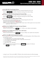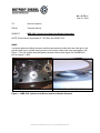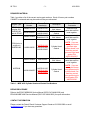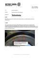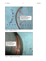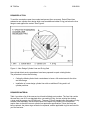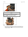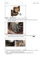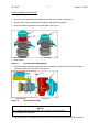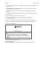
1
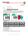
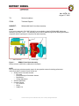
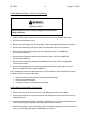
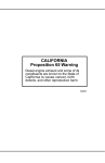
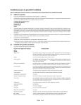
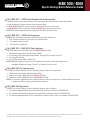
MBE 900 / 4000
Eparts Catalog Quick Reference Guide
(ALL) MBE 900 / 4000 Serial Number Break Information
Footnotes under certain parts contain important usage and serial number break information.
Certain footnotes in eParts contain German terminology.
For BIS MOTOR 833529, use Part number TO engine serial number break.
For AB MOTOR 833530, use Part number FROM engine serial number break.
NOTE: BIS/AB denotes the last six (6) digits of the serial number break.
(ALL) MBE 900 / 4000 Kit Information
NEW: eParts can denote kits with a prefix before the part description
1. “RS” stands for Repair Kit (Common for overhaul kits.)
2. “TS” stands for Service Kit
3. “DS” stand for Gasket Kit
(ALL) MBE 900 / MBE 4000 Fuel Injectors
MBE Fuel Injectors are located in the CYLINDER HEAD section.
1. Obtain and verify Engine Serial Number (ESN)
2. If not using ESN, select appropriate model. If using ESN, proceed to step 3.
3. Go to Engine Housing
4. Go Cylinder Head, Valves, Gasket Kit
NOTE: Multiple images are shown in the Cylinder Head, Valves, and Gasket Kit section.
Navigate through the image “Figures” to locate the correct part.
(ALL) MBE 900 Air Compressors
DO NOT use eParts Catalog. Use the following steps to order Air Compressor
1. Obtain and verify Engine Serial Number (ESN)
2. Order part number RA9061301415 TO ESN 455948.
3. Order part number RA9061304315 FROM ESN 455949.
NOTE: On occasion, applications are equipped with a unique air compressor. Confirm against current air
compressor before beginning the repair procedure.
(ALL) MBE 900 Flywheels
DO NOT use eParts Catalog. Use the following steps to order Flywheel.
1. For vehicles equipped with manual transmission, order part number A9060305905
2. For vehicles equipped with automatic transmission, order part number A9060300859
3. For vehicles equipped with a Euro specifications SACHS clutch, order part number A9060303405
Specifications are subject to change without notice. Detroit Diesel and the Spinning Arrows design are registered trademarks of the Detroit Diesel Corporation.
Copyright © 2009, Detroit Diesel Corporation. All rights reserved. Detroit Diesel Corporation is a Daimler company.
MBE 900 / 4000
Eparts Catalog Quick Reference Guide
(ALL) MBE 4000 Front Sump Oil Pans
Serial number break at 460933U0833530. Oil pan capacity changed from 40L to 36L.
Reference 06 TS–03Rev (January 30th, 2006) before ordering parts in eParts Catalog.
(EPA 04, 07) MBE 4000 Front Sump Die Casting Oil Pan
Part A4600100913 shown as an option in eParts is not serviceable. Do not order.
Reference 06 TS–03Rev (January 30th, 2006) before ordering parts in eParts Catalog.
(EPA 04, 07) MBE 4000 Rear Sump Oil Pans
Serial number break at 460933U0833530. Oil pan capacity changed from 40L to 36L.
Order part number A4760101013 TO ESN 833529.
Order part number A4600100813 FROM ESN 833530.
NOTE: On occasion, applications are equipped with a unique oil pan. Confirm against current oil pan before
beginning the repair procedure.
(EPA 98, 04, 07) MBE 4000 Cylinder Head and Gaskets
DO NOT use eParts Catalog.
Reference Technical Service Letter 09 TS-11 (April 21, 2009) to order cylinder head and gaskets.
(EPA 98, 04, 07) MBE 4000 Cylinder Liners and Pistons
DO NOT use eParts Catalog.
Reference Technical Service Letter 08 TS-8Rev (February 29, 2008) to order cylinder liners and pistons.
(EPA 98, 04) MBE 4000 Turbobrake Assembly
Turbocharger NOT serviceable for turbobrake assembly. Use the following steps in eParts Catalog to order
the turbobrake assembly.
1. Go to MBE catalog or enter Engine Serial Number (ESN)
2. If not using ESN, select appropriate model. If using ESN, proceed to step 3.
3. Go to Fuel Filter and Turbocharger
4. Go to turbocharger
5. Select Call out “20” Turbobrake
NOTE: Only engine brake is serviceable. Reference AP2006-036 (September 25, 2006) and
06 TS-22 (August 17, 2006)
Looking for more? Check out the MBE / DD Platform Parts tutorial located on the eParts homepage.
Specifications are subject to change without notice. Detroit Diesel and the Spinning Arrows design are registered trademarks of the Detroit Diesel Corporation.
Copyright © 2009, Detroit Diesel Corporation. All rights reserved. Detroit Diesel Corporation is a Daimler company.
No.: 09 TS-11
April 21, 2009
TO:
Service Locations
FROM:
Technical Service
SUBJECT:
MBE 4000 Cylinder Head And Head Gasket Information
NOTE: This document supersedes 07 TS-04Rev and AP2007-014.
ISSUE
A recessed grommet sealing area was machined around each coolant inlet and outlet port in the
cylinder head to give a better mating surface for the thicker rubber seal in the head gasket. See
Figure 1. The new cylinder head and gasket became effective with engine S/N: 0460866443
built on August 1, 2006.
Current Cylinder Head With Recess
Current Head Gasket With Raised Grommet
Figure 1 – MBE 4000 Cylinder Head Recess and Head Gasket Grommet
Detroit Diesel 13400 Outer Drive, West / Detroit, Michigan 48239-4001
09 TS-11
-2-
4/21/2009
Further improvements to the cylinder head is a change to a cast iron cup plug instead of a steel
cup plug to prevent head cracking. See Figure 2. The new cylinder head became effective with
engine S/N: 0460884866 built on April 25th, 2007.
Former Steel Cup Plug
Current Cast Iron Cup Plug
Figure 2 – MBE 4000 Cylinder Head Cup Plug
Another improvement to the head gasket includes the removal of the vent gap around the
perimeter of the gasket. This will prevent water intrusion under the gasket which can cause
rusting and pitting of the fire deck surfaces of the cylinder block and head, but ultimately does
not affect the sealing surfaces. See Figure 3. The new cylinder head gasket became effective
with engine S/N: 0460896913 built on September 3rd, 2007.
Former Gasket With Open Vent Gap
Current Gasket With Closed Vent Gap
Figure 3 – MBE 4000 Cylinder Head Gasket Vent Gap
REQUIRED ACTION
Note these items when servicing the cylinder heads and gaskets.
• Grommet style cylinder heads and gaskets MUST be used together on the same
cylinder. Do NOT mix grommet and non-grommet style cylinder heads and gaskets on
the same cylinder.
• Grommet and non-grommet style cylinder heads and gaskets can be used in the same
engine provided they are matched as noted above. Do NOT replace all six cylinder
heads and gaskets simply to have all the same new parts on the engine.
• Reference Technical Service letter 09 TS-9 for more information.
09 TS-11
-3-
4/21/2009
REQUIRED MATERIAL
Table 1 provides a list of the current service part numbers. Stock of former part numbers
CANNOT be returned and may be used until they are exhausted.
Engine Type
EPA04 after
engine S/N:
0460866443
and all EPA07
Current Part
Number
Former Part
Number(s)
RA4600101720
R4600101120
A460016042027
RA4600102020
EPA04 prior to
engine s/n
0460866443
A4570161220
A4600160420
R4600101120
RA4600101720
Description
Cylinder Head
with Valves
Cylinder Head
Gasket
Cylinder Head
with Valves
A4600160520
A4570161120
A4570161220
A4600160420
Cylinder Head
Gasket
RA4570108620
4600100620
Cylinder Head
with Valves
All EPA98
A460016042027
A4570161120
A4570161220
A4600160420
Cylinder Head
Gasket
Current Part
Comments
Grommet style
parts that must be
used together.
Non-grommet style
parts that must be
used together.
NOTE: If you are
reusing the former
grommet style
cylinder heads, use
matching current
grommet style head
gasket P/N:
A460016042027.
Grommet style
parts that must be
used together.
NOTE: If you are
reusing the former
non-grommet style
cylinder head, use
matching current
non-grommet style
head gasket P/N:
A4600160520.
Table 1 – MBE 4000 Cylinder Head and Gasket Part Numbers
REPAIR PROCEDURE
Refer to the EPA07 MBE4000 Service Manual (DDC-SVC-MAN-0026) and
EPA04/98 MBE 4000 Service Manual (DDC-SVC-MAN-0023) for repair information.
CONTACT INFORMATION
Please contact the Detroit Diesel Customer Support Center at 313-592-5800 or email
[email protected] if you have any questions.
No.: 08 TS-8Rev
February 29, 2008
TO:
Service Locations
FROM:
Technical Support Development
SUBJECT:
MBE 4000 Coolant Leaks
ISSUE
MBE 4000 engines may exhibit a high mileage concern of coolant leakage around the
cylinder liner.
CAUSE
The current stainless steel shim installed between the cylinder liner and cylinder block
counterbore area cannot adequately seal out coolant in this area. The coolant acts as a
lubricant, causing movement between the cylinder liner and cylinder block and subsequent wear
in the counterbore area. Coolant will then leak past the counterbore area. See below for pictures
showing the affected areas.
Figure 1 – Leakage in the Counterbore Area
Detroit Diesel 13400 Outer Drive, West / Detroit, Michigan 48239-4001
08 TS-8Rev
Figure 2 – Leakage on the Shim
Figure 3 – Leakage on the Liner Flange
-2-
2/29/2008
08 TS-8Rev
-3-
2/29/2008
REQUIRED ACTION
To seal the counterbore area from coolant and prevent liner movement, Detroit Diesel has
released a new cylinder liner design which uses an additional rubber D-ring just below the liner
flange to seal against the coolant. See Figure 4.
Figure 4 – New Design Cylinder Liner and D-ring Seal
New cylinder block service procedures have been prepared to repair existing blocks.
The procedure involves the following:
•
Cutting the failed cylinder block counterbores to leave a full contact area for the shim
and liner flange.
•
Installation of a new design cylinder liner with an additional D-ring seal in all
cylinder positions.
REQUIRED MATERIAL
Table 1 provides a list of the new service kit and individual part numbers. The liner kits contain
the new liner, new 0.15 mm standard shim, new sealing D-ring, the two existing liner bottom
o-rings, and the scraper ring (EPA04 only). The new 0.15 mm standard shim and sealing D-ring
are also listed separately, as are thicker shims if the depth of the freshly cut counterbores
require them to reach the correct cylinder liner protrusion specifications. Since the liners are
being replaced, the piston rings must also be replaced, and the applicable ring kits are listed for
your convenience.
08 TS-8Rev
-4-
A4600102050
A4600101950
Former Part
Number
A4600110610
A4600110210
A4609970045
NA
A4600110159
A4570110259
A4600110359
A4600110459
NA, use former ⇒
NA, use former ⇒
NA, use former ⇒
A4570110459
A4570110559
A4600300424
A4600300324
A4600300124
New Part Number
2/29/2008
Description
EPA04 and EPA07 EGR Cylinder Liner Kit
EPA98 Non-EGR Cylinder Liner Kit
Cylinder Liner D-Ring –
Contained In New Liner Kits
Cylinder Liner Shim (0.15 mm) –
Contained In New Liner Kits
Cylinder Liner Shim (0.3 mm) – As Needed
Cylinder Liner Shim (0.5 mm) – As Needed
EPA07 EGR Piston Ring Kit
EPA04 EGR Piston Ring Kit
EPA98 non-EGR Piston Ring Kit
Table 1 – MBE 4000 Cylinder Block Counterbore Repair Parts
REPAIR PROCEDURE
•
Reference SIB 08 MBE 4000-1Rev (EPA07) and SIB 08 MBE 4000-1Rev (EPA04) for
information on cutting the cylinder block counterbores using the existing Kent-Moore
PT-2250-B Porta-Tool.
•
Only the FAILED cylinders should have their counterbores cut. This decision is based on
the condition of the cylinder block counterbore sealing area. See Figures 1-3 on pages
1 and 2 for examples of failed counterbores.
•
The machining of the counterbores MUST be done correctly to accept the cylinder liner
shim and arrive at the correct liner protrusion specifications as listed in the EPA07 MBE
4000 Workshop Manual, DDC-SVC-MAN-0026 (6SE420) and MBE 4000 Workshop
Manual, DDC-SVC-MAN-0023 (6SE412).
•
ALL liners must be replaced with the new version and D-ring, even if that particular
cylinder is not having its counterbore cut. Installation of the new liner and D-ring seal
should prevent future failures.
•
Ensure that the new liner diameter tolerance code corresponds to the one marked on the
piston. The new liners should have a tolerance code B which requires a piston of either
code BA or BC. Reference to sections 1.4.3 and 1.19.1.1 in the EPA07 MBE 4000
Workshop Manual, DDC-SVC-MAN-0026 (6SE420) and sections 1.3.2 and 1.18.1.1 in
the MBE 4000 Workshop Manual, DDC-SVC-MAN-0023 (6SE412).
•
Start the repair by measuring the liner protrusion. Install the new liner with the new
standard 0.15mm shim and measure the liner protrusion as noted by
SIB 08 MBE 4000-1Rev (EPA07) and SIB 08 MBE 4000-1Rev (EPA04). Do NOT install
the D-ring & O-ring at this point. Mark the liners for cylinder position.
•
If the liner protrusion values are not within specifications, then you will need to cut the
counterbore. Reference section 1.4.1.3 in the EPA07 MBE 4000 Workshop Manual,
DDC-SVC-MAN-0026 (6SE420) and section 1.3.1.2 in the MBE 4000 Workshop Manual,
DDC-SVC-MAN-0023 (6SE412) for cylinder liner protrusion specifications.
08 TS-8Rev
-5-
2/29/2008
•
Install the new D-ring to the cylinder liner. Make sure the D-ring is installed dry with the
flat surface against the vertical face of the liner. See Figure 4 above, and
SIB 08 MBE 4000-1Rev (EPA07) and SIB 08 MBE 4000-1Rev (EPA04). Be careful not
to over-stretch the D-ring when it is installed over the liner flange.
•
The shim MUST be installed into the cylinder block, not on the liner.
•
Before installing the cylinder liner with D-ring into the cylinder block, apply a light coating
of clean engine oil to the D-ring.
•
Ensure the D-ring doesn’t roll or twist when installing the liner into the block.
•
Measure liner protrusion again. Follow the directions in 08 MBE 4000-1Rev (EPA07) and
SIB 08 MBE 4000-1Rev (EPA04). The values should be the same as measured above.
If not, remove the liner and check the installation.
•
If re-using the pistons, be sure to install new piston rings.
•
If installing new pistons, be sure to select the correct piston and piston cooling nozzle.
Reference Technical Service letter 05 TS-55Rev2. Please note that the current piston
kits (which contain the piston and liner) do NOT contain the new liner. Order only the
individual piston and cooling nozzle.
•
Before installing the cylinder heads, ensure they are not worn or defective which may
contribute to coolant leaks. For example, look for cracks around the cup plug on the rear
face of the heads.
CONTACT INFORMATION
Please contact the Detroit Diesel Customer Support Center at 313-592-5800 or email
[email protected] if you have any questions.
No.: AP2006-036
September 25, 2006
TO:
Service Locations
FROM:
Part Sales and Marketing
SUBJECT :
MBE 4000 Turbo Brake Assembly Service Parts
PRODUCT GENERAL INFORMATION
A new service assembly (P/N: R4571401206) is now available to install a REMAN MBE 4000 brake
assembly, see Figure 1. This assembly can be used to address engines with braking performance issues
without replacing the complete turbocharger assembly, see Figure 2. This new service assembly is
compatible with 4601400171, 4601400271 and 4571400071—parts no longer serviced.
Figure 1 Brake Assembly
Figure 2 Turbo Brake Assembly=1-Brake Assembly and 2-Turbocharger
PART NUMBER
Non-serviced
Part Numbers
New Part
Numbers
N/A
4601400171
4601400271
4571400071
N/A
E 4601400171
E 4601400271
E 4571400071
reliabilt® Part
Numbers
R 4571401206
R 4601400171
R 4601400271
R 4571400071
Description
Brake assembly
turbo brake assembly
turbo brake assembly
turbo brake assembly
APPLICABLE ENGINE LINES
All MBE 4000 engines equipped with the turbo brake assembly, EGR and Pre-EGR.
ADDITIONAL INFORMATION
Please see 18SP635 for installation instructions.
CONTACT INFORMATION
Please make sure all affected areas of your organization receive a copy of this letter.
Contact your service location’s parts field sales representative for more information.
Detroit Diesel Corporation 13400 Outer Drive, West / Detroit, Michigan 48239-4001
DA 1
No.: 06 TS - 22
August 17, 2006
TO:
Service Locations
FROM:
Technical Support
SUBJECT:
REMAN MBE 4000 Turbo Brake Assembly
ISSUE
A new service assembly (P/N: R4571401206) is now available to install a REMAN MBE 4000 brake
assembly, see Figure 1, No.1. This assembly can be used to address engines with braking performance
complaints without replacing the complete turbo brake assembly.
1.
Brake Assembly
Figure 1
2.
Turbocharger
REMAN Turbo Brake Assembly
Please reference 18SP635 for additional kit information.
NOTE:
Prior to performing a brake assembly repair, all other possible causes for braking performance
concerns should be reviewed. Some causes are:
• Sliding Sleeve Pneumatic Actuator
o Air Supply
o Internal Damage to Pneumatic Actuator
o Bent Bracket
o Linkage Adjustment
• Software Calibration
• Constant Throttle
o CTV Solenoid
o Wiring
o Supply Line
Detroit Diesel Corporation 13400 Outer Drive, West / Detroit, Michigan 48239-4001
DA 1
06 TS-22
-2-
August 17, 2006
TURBO BRAKE ASSEMBLY REMOVAL PROCEDURE
Remove the turbocharger from the engine as follows:
PERSONAL INJURY
To avoid injury before starting and running the engine, ensure the
vehicle is parked on a level surface, parking brake is set, and the
wheels are blocked.
1. Apply the parking brake, chock the wheels, and perform any other applicable safety steps.
2. Disconnect vehicle battery power.
3. Remove the exhaust pipe from the turbocharger. Refer to the applicable vehicle service manual.
4. Remove the turbocharger inlet air pipe. Refer to the applicable vehicle service manual.
5. Remove the oil feed and return pipes from the turbocharger. Refer to the MBE 4000
Service Manual (6SE412).
6. Disconnect the turbocharger speed sensor harness connector. Refer to the MBE 4000
Service Manual (6SE412).
7. Disconnect the turbocharger wastegate and sliding sleeve air lines. Refer to the applicable
vehicle service manual.
8. Remove the turbocharger from the exhaust manifold and place the turbocharger on a bench.
Refer to the MBE 4000 Service Manual (6SE412).
Prior to disassembly of the turbo brake assembly, a routine inspection of the turbocharger should be
completed. Areas of concern could include:
•
•
•
•
Evidence of foreign objects entering and exiting the turbocharger
Evidence of restricted air flow
Evidence of lack of lubrication
Evidence of turbine or compressor wheel damage
TURBO BRAKE DISASSEMBLY PROCEDURE
Disassemble the turbo brake as follows:
1. Remove the clevis pin from the ball socket on the sliding sleeve actuator and discard.
2. Using a large screw driver or pry bar, disconnect the sliding sleeve actuator ball socket from the
sliding sleeve lever.
3. Inspect the sliding sleeve actuator for damage or binding and try to move the sliding sleeve lever.
This is used as a general inspection and may pinpoint the area of concern.
4. Remove the two bolts (1) and v-band clamp (3) from the exhaust bypass pipe (2). Discard the two
bolts (1), but save pipe and clamp for reinstallation. See Figure 2.
06 TS-22
-3-
August 17, 2006
5. Remove the four (4) nuts holding the brake assembly to the housing and discard. See Figure 2.
1.
2.
Bolt (2 qty.)
Exhaust Bypass Pipe
Figure 2
3.
4.
V-Band Clamp
Nut (4 qty.)
Exhaust Bypass Pipe and Brake Assembly Nuts
6. Separate the assembly from the turbocharger housing. Set the turbocharger horizontally on a
sturdy table. Protect the speed sensor and wiring from damage.
a) Using a brass hammer, tap the turbocharger housing equally on two sides until a small gap is
generated around the mating surface of the brake assembly and turbocharger housing. Do
NOT hit the exhaust pipe connecting flange. See Figure 3.
b) Once a gap is generated, use a large screwdriver or pry bar to apply even leverage 180° apart
to separate the brake from the turbocharger housing. See bold arrows in Figure 3. Try to keep
the brake assembly as straight as possible when removing.
1.
Exhaust Pipe Connecting Flange
Figure 3
Leverage Points
NOTE:
During most disassemblies the matrix usually stays in the turbocharger housing due to tight tolerance,
and a slight build up of rust. See Figure 4.
06 TS-22
1.
-4-
August 17, 2006
Matrix
Figure 4
Matrix Still Inside Housing
7. To remove the Matrix from the turbocharger housing do the following:
a) Use an emery cloth to clean the edge of the turbocharger housing just above the Matrix lip.
Do NOT use a die grinder or a powered sander. See Figure 5.
1.
Housing
Figure 5
2.
Matrix Lip
Matrix Lip and Housing
b) Apply a small amount of penetrating oil just above the Matrix lip around the entire radius and
allow it to set for a few minutes. The penetrating oil will seep down along the walls allowing the
Matrix to be removed without damage. See Figure 6.
06 TS-22
Figure 6
-5-
August 17, 2006
Applying Penetrating Oil to Matrix Lip
NOTICE:
If the Matrix will not turn by hand after penetrating oil has been applied,
use a non marring strap wrench near the base to provide extra
leverage. Do NOT hit the side of the Matrix. A rocking motion can cause
damage to the Matrix or the turbine blades. See Figure 7.
Figure 7
Broken Matrix (separated)
c) Grab the Matrix with two hands and rotate it back and forth while pulling straight up. If the
Matrix binds up, lightly tap the TOP with a rubber mallet to re-seat it in the bore. Re-inspect
the housing bore for a lip and remove if necessary. Continue the process until the Matrix
is removed. See Figure 8.
06 TS-22
-6-
August 17, 2006
Figure 8
Matrix Removal
8. Do the following to inspect the turbine blades and housing for wear:
a) Inspect the turbine blades for wear, cracks, chips, or evidence of foreign material entering the
turbocharger. See Figure 9.
Figure 9
Checking Turbine Blades for wear
b) Inspect the inside of the housing for single or multiple cracks. The housing can ONLY be
reused if the cracks do not intersect. See Figure 10.
1.
Single Crack (No intersecting cracks – reuseable)
Figure 10
2. Multiple Cracks (Intersecting cracks – non- reusable)
Intersecting vs. Non-Intersecting Cracks
9. Use an emery cloth and clean all mating surfaces between the housing and the new
brake assembly.
06 TS-22
-7-
August 17, 2006
BRAKE ASSEMBLY PROCEDURE
Assemble the brake as follows:
1. Place the brake assembly and turbocharger housing on their sides, see Figure 12.
2. Remove the tie wrap holding the Matrix together with the brake assembly.
3. Ensure the Matrix is seated over the guide baffle. See Figure 11.
1.
2.
Non-seated Matrix
Seated Matrix
Figure 11
3.
Guide Baffle
Non-Seated and Seated Matrix
4. Ensure the brake assembly is parallel to the turbocharger housing and slide the two assemblies
together until they are fully seated. See Figure 12.
1.
Brake Assembly
Figure 12
2.
Turbocharger
Turbo Brake Assembly
NOTICE:
Due to the tight tolerance of the Matrix to the housing, care must be taken
not to damage either assembly.
5. Install and torque in a diagonal sequence the four turbo brake assembly nuts to 40 N·m (29 lb-ft).
06 TS-22
-8-
August 17, 2006
6. Install the exhaust bypass tube flange to the brake assembly using two M8 X 16 bolts and torque to
30 N·m (22 lb-ft).
7. Install the opposite end of the exhaust bypass tube to the turbocharger housing and torque the
v-band clamp bolt to 5-7 N·m (4-5 lb-ft).
8. Connect the turbocharger to the exhaust manifold. Refer to the MBE 4000 Service Manual
(6SE412).
9. Connect the turbocharger wastegate and sliding sleeve air lines. Refer to the applicable vehicle
service manual.
10. Connect the turbocharger speed sensor harness connector.
11. Connect the oil feed and return pipes to the turbocharger. Refer to the MBE 4000
Service Manual (6SE412).
12. Connect the turbocharger inlet air pipe. Refer to the MBE 4000 Service Manual (6SE412).
13. Connect the exhaust pipe to the turbocharger. Refer to the applicable vehicle service manual.
14. Connect vehicle battery power.
PERSONAL INJURY
Diesel engine exhaust and some of its constituents are known to the
State of California to cause cancer, birth defects, and other reproductive
harm.
• Always start and operate an engine in a well ventilated area.
• If operating an engine in an enclosed area, vent the exhaust to the
outside.
• Do not modify or tamper with the exhaust system or emission control
system.
15. Start engine and check for air or oil leaks.
CONTACT INFORMATION
Please contact the DDC Customer Support Center at 313-592-5800 if you have any questions.
No.: 06 TS – 03Rev
January 30, 2006
TO:
DDC Distributors, FLLC Dealers
FROM:
Technical Service
SUBJECT:
New Oil Pan For MBE4000 Engines
ISSUE
New 36L capacity front sump oil pan for certain MBE4000 engines.
ADDITIONAL INFORMATION
MBE has installed a new front sump oil pan (P/N: 4600100713) that contains 36L (38 qt.) of oil
instead of the former 40L (42.3 qt.) oil pan (P/N: 4760100913) effective with engine serial
number 0460833530.
• Do not overfill the crankcase when filling the engine with oil. Refer to the MBE4000
Operators Guide (6SE411) for information on correctly filling the engine with oil and
checking the level on the dipstick.
• The new oil pan is used on the following engines:
o All EGR engines with front sump
o Non-EGR engines with front sump for Right Hand Drive export applications
(Australia, New Zealand, etc.)
• The new oil pan is NOT used on the following engines:
o Non-EGR engines with front sump for Left Hand Drive applications (Mexico, etc.)
o Any rear sump application
o These engines will convert to the new 36L pan in late 2006
• Other new parts associated with this change are:
o Oil pickup tube
o Dipstick and dipstick tube
o Oil fill tube
o Bracket for dipstick tube and oil fill tube
o Oil centrifuge cover
• Do NOT install the new 36L oil pan on an engine that was built with a 40L oil pan without
fully investigating all of the changes between the two particular engines
• Engines with the new oil pan are identified with a “36L” sticker on the engine oil fill cap
(See Figure 1 below)
Detroit Diesel Corporation 13400 Outer Drive, West / Detroit, Michigan 48239-4001
DA 1
06 TS-03Rev
-2-
January 30, 2006
Figure 1 – Identifying Label on Engine Oil Fill Cap
CONTACT INFORMATION
Please contact the DDC Customer Support Center at 313-592-5800 if you have any questions.