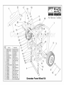
1
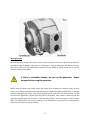
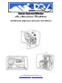
Denver Concrete Vibrator
An American Tradition
4E-180 Series High-Cycle Generator User Manual
1463 W. Alameda Ave., Denver, CO 80223 USA
Phone 303-778-8832 / 800-392-6703 Toll Free / FAX 303-778-8682
www.denverconcretevibrator.com / [email protected]
Table of Contents
Table of Contents ……………………………………………………………………………………………….
pg 2
Important Safety Instructions ………………………………………………………..
pg 3
Introduction ………………………………………………………………………………….
pg 4
Grounding …………………………………………………………………………………….
pg 5
Getting Started …………………………………………………………………………….
pg 6
Using the Tool ………………………………………………………………………………
pg 7
Use of Extension Cords …………………………………………………………………
pg 7
Maintenance ………………………………………………………………………………..
pg 7
Storage …………………………………………………………………………………………
pg 8
Technical Information …………………………………………………………………..
pg 8
Outlet Box Wiring …………………………………………………………………………
pg 9
Drive Unit Specifications ………………………………………………………………
pg 10
Parts Breakdown, generator …………………………………………………………
pg 11
Parts Breakdown, wheel kit ………………………………………………………….
pg 12
Warranty Statement ……………………………………………………………………
pg 13
OSHA Fact Sheet
“Grounding Requirements for Portable Generators” ………………….
pgs 14-15
2
IMPORTANT SAFETY INSTRUCTIONS
Rules for safe 4E-180 series generator operation:
Failure to follow these instructions may lead to serious injury or even death.
This equipment is to be operated by trained and qualified personnel only.
Do Not operate this equipment before reading this information.
•
•
•
•
•
•
•
•
•
•
•
•
•
•
•
•
Do not work alone.
Know how to stop the engine quickly and understand how to operate all of the controls.
Check engine oil level prior to each use and add as necessary before starting engine.
Always wear personal protective clothing, safety glasses and other personal protection devices according
to the rules of the work area.
Read, understand and follow any and all brand specific information provided by the particular engine or
motor manufacturer.
Generators are a source of potentially lethal high voltage and should be operated by qualified personnel
only.
Do not operate electrical equipment standing in water, with wet hands or in the rain. Electrical shock
could occur causing bodily harm or even death.
Use adequately sized connecting cable for extension cords.
Maintain electrical cords in good condition and have damage repaired by qualified personnel prior to use.
Damaged, frayed or exposed wiring can result in electrical shock causing severe bodily harm or even
death.
To reduce fire hazards and provide adequate ventilation keep internal combustion engines at least 3ft
(1m) away from buildings, combustible materials and other equipment during operation. Operate the
equipment on level or very nearly level surfaces. Do not put the engine powered generator indoors while
the engine is still hot.
Always use extreme caution when handling flammable liquids. Fumes are combustible. Always refuel only
in a well ventilated area away from sparks and open flame. Never refuel a hot or running engine. Fire or
explosion could result from fuel vapors or fuel spilled on a hot engine. Stop the engine and allow engine
to cool before re-fueling. Do not smoke around the machine while refueling. Promptly clean up any
spilled fuel. Failure to follow these recommendations could result in bodily harm or death.
This generator is equipped with a ground terminal and the generator must be grounded to an external
grounding source. Ground the generator from the lug provided by the manufacturer according to Federal,
State and local codes for site conditions. Failure to properly ground this equipment can result in serious
bodily harm or death.
Operate internal combustion engine-driven generators only in well-ventilated areas to avoid deadly
carbon monoxide build-up and / or excessive heat due to lack of air flow. This can result in serious bodily
harm or even death.
Never operate generator in an explosive atmosphere. This can result in serious bodily harm or death.
Check all tools powered by the generator for proper ground or circuit protection.
Always wear rubber boots and gloves as added protection when operating a concrete vibrator or similar
device immersed in a water based solution.
Emergency Preparedness:
• Know the location of the nearest fire extinguisher and first aid kit.
• Know how to contact the nearest ambulance and/or Fire Department
3
Denver Vibrator 4E-180 series High-Cycle Generator
This portion of the manual covers the Generator Section (driven power
producing section) only. Manuals for the drive section using a Honda Gasoline Engine, Yanmar
Diesel Engine, Baldor Electric Motor or other power source is provided by the specific manufacturer of
the drive unit and was included with the generator as a separate manual. Based upon the power source
of your high-cycle generator, please refer to the specific manufacturer’s manual for information on the
drive unit.
Please read this manual, all safety information and the drive unit manual in their entirety before
operating the generator.
WARNING! When operating, the High-Cycle Generator produces an
electrical current and can cause injury or even death if used
improperly.
The Denver High-Cycle Generator is designed to produce 3-Phase, 180 Hertz (High Cycle) electricity and
can be wired for either 115 volt or 230 volt (230 volt is the factory setting) and is intended to be used to
provide the power to a high-cycle concrete vibrator that has been designed to operate on the supplied
power. The Denver High-Cycle Generator cannot be used to provide power to single-phase equipment
or 3-Phase equipment that requires a power supply that is something other than 180 Hertz (i.e. 60
Hertz)
WARNING! Making modifications to the Generator Section will
void the warranty and may result in injury or even death.
The electricity produced by the Generator Section is supplied to two (2) 7410 receptacles located on the
front of the Generator Section (see Fig. 1). The receptacles are designed for a 4-pronged, 3-phase, 7411
twist-lock plug. To insert the plug, make sure that the prongs of the plug line up to the appropriate slots
in the receptacle and push all the way in. Once the plug has been fully inserted, twist it to the right
(clockwise) to lock the plug into the receptacle. To remove the plug from the receptacle, twist the plug
to the left (counterclockwise) to unlock and then pull the plug straight out to remove.
4
Grounding
WARNING! Before using the generator make sure that it is properly
grounded according to National, State and local codes per site
conditions. Consult with a competent, qualified electrician. Failure
to properly ground the generator is a potential shock hazard and
may result in injury or death.
Before starting the generator or connecting power tools to the receptacles, make sure that the
generator is properly grounded according to National, State and local codes per site conditions. Ground
the generator using the grounding lug located on the cover plate of the Generator Section (see Fig. 1) to
a grounding electrode such as a ground rod with minimum #8 gauge wire. Resistance to ground should
measure 500 ohms or less. Note: As normally configured, the engine/generator assembly is isolated
from the frame using rubber mounts.
Simply placing the frame on the ground will not provide a proper grounding connection.
Per OSHA Fact Sheet, “Grounding Requirements for Portable Generators”
Bonding Versus Grounding…
“Bonding and grounding are separate requirements for generators and other electrical distribution
systems. Grounding means the connection, or the establishment of a connection, of an electric circuit or
equipment to reference ground, which includes the generator’s frame. Bonding is the intentional
connection between the grounded circuit conductor (neutral) and the grounding means for the
generator, which includes the generator’s frame. Thus, effective bonding of the neutral conductor to the
generator’s frame is also a concern for the safe use of the equipment. As with grounding terminal
connections, proper bonding of the neutral terminal of a power receptacle may be confirmed via testing
by a competent electrician with the correct equipment, and the ohmic resistance should measure near
zero and must not be intermittent, which indicates a loose connection.”
As a source of additional information, please see the complete OSHA Fact Sheet “Grounding
Requirements for Portable Generators” regarding proper grounding of portable generators included as
a separate flyer in the literature sent with the generator.
Grounding by placing the frame on the ground may be achieved if the engine/generator assembly is
bonded to the frame. If the generator has a wheel kit or is positioned in such a manner that the frame is
elevated and/or isolated from the earth then grounding must be accomplished by using the grounding
lug and a grounding electrode such as a ground rod per National, State and local codes per site
conditions; otherwise, proper grounding will not be achieved.
Consult a competent and qualified electrician when determining how to properly ground or modify
this generator assembly per National, State and Local codes per site conditions.
5
Getting Started
Before using the generator, always do a visual pre-start inspection of the entire generator assembly for
any obvious signs of damage, leaks, loose or missing parts. Check all fluid levels and add as necessary.
Also, refer to the drive unit manufacturer’s (Honda, Yanmar, Baldor or other) manual for any specific
pre-start inspection procedure.
If there is noticeable damage, do not use the generator. Repair
damage before using the generator.
Before using any power tool always inspect the power cord, including any extension cords, for bare
wires, cuts or bulges and that both the cord and plug are in good and useable condition with no damage,
including missing ground prongs. After proper grounding of the generator has been achieved, connect
the tool to the generator by inserting the plug into the receptacle. Next, check to make sure that the
Start/Stop (on/off) switch for the tool is in the Stop (off) position. Start the engine or motor (HCMG180-1 and HCMG-180-3 units only) according to the manufactures instructions (see manufacturer’s
manual for the proper start-up procedure).
6
Inspect the running engine and generator section for any loose parts, odd noises, leaks or unusual odors.
If any problems are noticed, correct the problem or contact our factory at (800) 395-6703 for further
instructions or assistance. If everything appears to be operating normally, proceed to the next step.
Using the Power Tool
Once the generator has been determined to be properly grounded and in good working condition, you
may proceed with using the tool. Turn the power tool on and check for proper rotation. Use according
to the tool manufacturer’s instructions and intent for how the tool is to be used. Once finished, turn off
the tool first and then shut down the engine or motor (see manufacturer’s manual for proper shut-off
procedure).
Use of Extension Cords:
Extension cords are to be sized based on distance and amperage so that the voltage drop between the
generator and the load (tool) is kept to a minimum.
For use with High Cycle concrete vibrators,
•
50’-100’ extension cords, 14 gauge wire is adequate.
If using longer extension cords or combining extension cords, consult a competent, qualified
electrician.
Repairs to extension cords should be performed by a competent, qualified electrician.
Maintenance
The Generator Section of the generator is maintenance-free and does not require regular servicing.
Keeping the generator section (including the vent holes on the side) clean and free of dirt, concrete and
other debris is all that is needed to keep the Generator Section in proper working order and ensuring
maximum life. Do not subject the generator to a direct stream from a water hose or pressure washer.
There are no user service parts inside the generator housing. For service or maintenance of the drive
section (Honda, Yanmar, Baldor or other), please refer to the manufacturer’s manual.
7
Storage
If the generator is not going to be used for an extended period of time then it is recommended that the
unit be stored indoors. If indoor storage is not possible, keep the unit covered and in a non-moist
environment. See the drive unit manufacturer’s (Honda, Yanmar, Baldor or other) manual for the
proper long term storage procedure (draining oil, fuel, etc…).
Technical Information
Generator Output Specifications:
Hertz*: 180 at 3600 RPM
Max Power Output: 4KW
Phase Output: 3-Phase only
Number of Receptacles: 2
Receptacle Number: 7410 / Plug Number: 7411
Voltage**: 230/115 Volt (Factory Setting is 240 volt)
Amp: 10/20
*Normal operating range of the engine is 3300 to 3650 rpm. The Hertz output will vary directly with
engine (drive unit) speed on a 1 to 1 ratio. A Hertz reading of the generator output will indicate the
speed of the engine. The Hertz range will be as follows: 3300 rpm – 165 Hertz, 3400 rpm – 170 Hertz,
3500 rpm – 175 Hertz, 3600 rpm – 180 Hertz, 3650 rpm – 182.5 Hertz. The engine should not operate
below 3300 rpm. Operating the engine below 3300 rpm may result in damage to the vibrator or
inconsistent performance of the vibrator. Equipment damaged due to an improperly tuned generator
will not be covered under warranty.
**The generator voltage output will vary with temperature and load. When testing, a generator’s
output will be 260 to 290 volts unloaded (no vibrators turned-on), 240 to 260 volts loaded with 1
vibrator running and 220 to 240 volts loaded with 2 vibrators running. The voltage output of the
generator when wired for 115 volts will be 130 to 145 volts, 120 to 130 volts and 110-120 volts,
respectively.
8
Outlet Box Wiring
For proper clockwise rotation the outlet box is wired as follows:
Standard 230V (High voltage) output:
•
•
•
•
•
•
•
Leads numbered 4 & 7 together
Leads numbered 5 & 8 together
Leads numbered 6 & 9 together
Lead numbered 1 to the X terminal on the outlet
Lead numbered 2 to the Y terminal on the outlet
Lead numbered 3 to the Z terminal on the outlet
Terminal W on the outlet is wired to the outlet frame and serves as the ground
Optional 115V (Low voltage) output:
•
•
•
•
•
Leads numbered 4, 5, & 6 together
Leads numbered 1 & 7 are combined to terminal X on the outlet
Leads numbered 2 & 8 are combined to terminal Y on the outlet
Leads numbered 3 & 9 are combined to terminal Z on the outlet
Terminal W on the outlet is wired to the outlet frame and serves as the ground
Caution: Reconnection for low voltage (115V) requires heavier 10 gauge stranded jumper wires from
the primary outlet terminals to the corresponding outlets on the secondary outlet.
Reconnection wiring or outlet replacement should be performed by a competent qualified electrician.
9
Optional Drive Unit Specifications:
Honda Gasoline Powered High-Cycle Generator
Model: HC4E-180H
Engine: 9hp Honda
Tank Capacity: 1.4 gallons
Run Time at ½ Load: 4 hours approximate
Dry Weight:
150 lbs
Yanmar Diesel Powered High-Cycle Generator
Models: HC4E-180Y (manual start) *
HC4E-180YE (electric start) **
Engine: 6 hp Yanmar
Tank Capacity: 0.87 gallons
Run Time at ½ Load: 3.5 hours approximate
Dry Weight:
176 lbs *
184 lbs. **
Baldor Electric Motor Driven High-Cycle Generator
Models: HCMG-180-1 (single phase input)
HCMG-180-3 (3 phase input)
Motor: 5 hp Baldor
Input Phase: Single Phase or 3-Phase
Input Voltage: 230V (Single Phase) 230/460V (3-Phase)
Input Hertz: 60 Hz
Gross Weight: 156 lbs
10
11
12
FactSheet
Grounding Requirements
for Portable Generators
Portable generators are internal combustion engines used to generate electricity.
They are useful when temporary or remote power is needed, and are commonly
used during cleanup and recovery efforts following disasters.
Major Causes of Injuries and Fatalities
• Shocks and electrocution to users from
improper use.
• Shocks and electrocution to utility workers
from improper connection to structures, such
as residences, offices, shops and trailers.
Safe Work Practices
• Maintain and operate portable generators
in accordance with the manufacturer’s use
and safety instructions.
• Never attach a portable generator directly
to the electrical system of a structure
(home, office or trailer) unless the generator has a properly installed open-transition
transfer switch.
• Always plug electrical appliances and tools
directly into the generator, using the appliance manufacturer’s supplied cords. Use
heavy-duty extension cords that contain a
grounding conductor (3-wire flexible cord
and 3-pronged cord connectors).
• Proper grounding and bonding are a means
to prevent shocks and electrocutions.
• Use ground-fault circuit interrupters (GFCIs)
as per the manufacturer’s instructions.
• Do not connect a generator to a structure
unless the generator has a properly
installed transfer switch.
• Visually inspect the equipment before use;
remove defective equipment from service;
mark or tag it as unsafe for use.
Grounding Requirements for Portable
and Vehicle-mounted Generators
Under the following conditions, OSHA
directs (29 CFR 1926.404(f)(3)(i)) that the
13
frame of a portable generator need not be
grounded (connected to earth) and that the
frame may serve as the ground (in place of
the earth):
• The generator supplies only equipment
mounted on the generator and/or cordand plug-connected equipment through
receptacles mounted on the generator,
§ 1926.404(f)(3)(i)(A), and
• The noncurrent-carrying metal parts of
equipment (such as the fuel tank, the internal combustion engine, and the generator’s
housing) are bonded to the generator
frame, and the equipment grounding conductor terminals (of the power receptacles
that are a part of [mounted on] the generator) are bonded to the generator frame,
§ 1926.404(f)(3)(i)(B).
Thus, rather than connect to a grounding
electrode system, such as a driven ground
rod, the generator’s frame replaces the
grounding electrode.
If these conditions do not exist, then a
grounding electrode, such as a ground rod,
is required.
If the portable generator is providing electric
power to a structure by connection via a
transfer switch to a structure (home, office,
shop, trailer, or similar) it must be connected
to a grounding electrode system, such as a
driven ground rod. The transfer switch must
be approved for the use and installed in
accordance with the manufacturer’s installation instructions by a qualified electrician.
Grounding requirements for generators connected via transfer switches are covered by
Article 250 of the National Electrical Code
(NEC).
Safe Work Practices for Portable Tools
include:
• Do not use underrated cords—replace
them with appropriately rated cords that
use heavier gauge wires.
• Never use electrical tools or appliances
with frayed cords, missing grounding
prongs, or damaged or cracked housings.
• Use double-insulated tools and equipment
distinctively marked as such, where possible.
• Use battery-operated tools, where possible.
Verification by Testing
The integrity of the connection between the
generator’s frame and the equipment
grounding terminals of power receptacles is
important to the safe use of the equipment.
The connection may be confirmed via testing
by a competent electrician with the correct
equipment. The ohmic resistance should
measure near zero and must not be intermittent, which indicates a loose connection.
Bonding Versus Grounding
Bonding and grounding are separate requirements for generators and other electrical distribution systems. Grounding means the connection, or the establishment of a connection, of an electric circuit or equipment to reference ground, which includes the generator’s frame. Bonding is the intentional connection between the grounded circuit conductor (neutral) and the grounding means for
the generator, which includes the generator’s
frame. Thus, effective bonding of the neutral
conductor to the generator’s frame is also a
concern for the safe use of the equipment. As
with grounding terminal connections, proper
bonding of the neutral terminal of a power
receptacle may be confirmed via testing by a
competent electrician with the correct equipment, and the ohmic resistance should measure near zero and must not be intermittent,
which indicates a loose connection.
This is one in a series of informational fact sheets highlighting OSHA programs, policies or
standards. It does not impose any new compliance requirements. For a comprehensive list of
compliance requirements of OSHA standards or regulations, refer to Title 29 of the Code of Federal
Regulations. This information will be made available to sensory impaired individuals upon request.
The voice phone is (202) 693-1999; teletypewriter (TTY) number: (877) 889-5627.
For more complete information:
U.S. Department of Labor
www.osha.gov
(800) 321-OSHA
DSTM 10/2005
14