1
,...
,P
U
A MlTSUBlSHl
I
,
ADVANCED AND EVER ADVANCING
VARIABLE FREQUENCY DRIVES
HIGHPOWER
HIGHPERFORMANCE
FULLY
DIGITAL
AC INVERTERS
PANEL ENCLOSURE BUILDING GUIDELINES
TABLE OF CONTENTS
1. INTRODUCTION ....................................................................................................
0
1
2. CONSTRUCTION OF VARIABLE-SPEED DRIVE SYSTEMS USING INVERTER......1
3. TYPES AND CONFIGURATIONS OF INVERTER PANEL ENCLOSURE ............3
4. PRECAUTIONS ON DESIGNING INVERTER PANELS
......................................
23
.....................................................
26
6. NOTES ON INSTALLATION OF THE INVERTER IN THE PANEL
.....................
35
5. SELECTING PERIPHERALSAND OPTIONS
7.TESTING .............................................................................................................. 39
0
8. PRECAUTIONS ON INVERTER INSTALLATION AND OPERATION
.................40
9. PRECAUTIONS ON OPERATIONAND MAINTENANCE OF INVERTERS ........41
i
0
rc..
/
1. INTRODUCTION
Your purchase of a Mitsubishi Transistor Inverter
MELTRAC-A series is greatly appreciated. To
use this inverter effectively and safely
it should be installed in a stand-alone control panel.In
addition,theinvertershouldbeelectricallyandmechanicallyprotected.Operationdevices,
monitor instruments, lamps and other components should beto laid
facilitate
out easy operation.
Sequential logic needsto be programmedto perform the desired operations.
This manual describesthe precautions and notesin preparing an inverter panel. Before using
MELTRAC-A series
this manual, thoroughly read the operation manuals and catalogs for the
equipment.
2. CONSTRUCTION OF VARIABLE-SPEED DRIVE SYSTEMS USING INVERTER
/-
2.1 ADVANTAGES OF INVERTER DRIVE SYSTEM
The inverter can easily control the speeds
of a squirrel-cage motor which alone would otherwise
operate at a fixed speed. Presently, the inverter is widely used as a most popular variable-s
drive system.
Some of the major advantagesof the inverter are as follows.
(1)The inverter is simple in construction and capable of controlling squirrel-cage
motors that are most generally used.
(2)The inverter steplessly controls motor speeds from low
to high.
(3)The inverter circuit and control panel are simple. They are compatible withFA
systems.
(4)The efficiency and power factor are high over the entire speed range.
(5)The inverter canbe hooked upto existing motors.
(6)Given the inverter, a backup system (fixed speed) can be configured easily on
commercial power source.
(7)The start-up current is small.
The following points should also be noted with the inverter from the hardware and system view
points.
(1)The inverter is a high-tech electronic device consisting
of a microcomputer and
power semiconductors. General precautions for electronic devices should be
exercised, such as installation in a proper environment and protection against
electrical noise from the power circuit.
(2)The PWM output voltage is obtained by switching at a high speed the direct cu
power which is produced by rectifying the commercial power.
(3)Squirrel-cage motors are designed basically
to be operated on the commercial
power source.
(4)Some squirrel-cage motors
of 45 kW or higher are made to special specifications
and therefore the characteristics are different from one motor to another.
(5)The loss of power increases along with the capacity. Adequate heat radiation
is
an important considerations.
(6)Large-capacitymotorsareusuallyresponsibleforimportantoperationsand
installations. The system reliabilityis therefore an important consideration.
(7)Slip is smaller (approximately 1O/.) with a largecapacity motor than with a small
one.
(8)The start-up torque tends
to be slow to buildwith the operation through the inverter
compared with the operation on the commercial power line.
1
2.2 PRECAUTIONS ON SYSTEM DESIGN
In order to design and build an optimal system that makes full use of the inverter drive, the
following shouldbe considered in advance.
(1)Only the parameter unit may be necessary for a single operation. However,
operation devices and monitor instruments should be installed to provide the
operator with better operation. When the operator panel is remote from the
inverter panel, an effective anti-noise measure should
be provided.
(2)For a simple interlocking
or interacting operation or a simple applied control, the
series operation panel or setting box
functions built-in the inverter may beA used.
may be installed as necessary.
(3)When using the inverter
as part of the entire system, use
the interface featuring
the I/O device of the MELSEC Programmable Logiccontroller i. e.
MELSECNET/MINI-S3 (optical fiber cables). (T-OPT22
is necessary.)
(4)When building a complex operation system, a manual backup system should be
installed.
(5)In an operation that does not tolerate even a momentarily power failure, install a
back-up system operating on the commercial power
in preparation
line
for inverter
trip. In this case, measures should be taken for maintenance and repairing the
inverter. Provide a sequence program that allows to reset to the inverter control.
started up on the commercial power. When operating
Check if the motor can be
loads having large Gp2, consider the voltage drop during starting up on the
commercial powerin evaluating the power source capacity.
(6)When operating the most critical system, design a redundant (dual) system with
a stand-by inverter and machine.
(7)Considertheconsequenceandresumption
of operationintheevent
of a
momentarily power failure or voltage drop that causes the inverter to run freely.
(8)lf the power source is small, consider the effect of the harmonics generated by the
inverter operating on the power system.
(9) Before selecting the inverter and motor capacities, properly evaluate the speedtorque characteristicsof the machines to be operated, start-up torque, acceleratiorddeceleration profile, instantaneous peak torque and ther relevant operating
characteristics.
(10) Check that the temperature stays within the allowable range when operating the
motor at low speeds. This is especially critical in a so-called constant-torque
operation which requires a large torque at low speeds.
(1 1) The inverter offers a variable speed operation. Check that the mechanical
resonance point does not exist within the speed range of the inverter operation.
(12) Before hooking the inverter
to an existing motor, check the motor for deterioration of insulation.
(13)Themotorproducesmorenoisethanthatproducedinoperationsonthe
commercial power source. Check if special noise prevention measures are
necessary.
(14) When applying the inverter
toa load that requires regenerative torque, check the
magnitude of regenerative energy and the frequency of regeneration.
GD2such as fans, check the practically
(15 ) When controlling loads having a large
optimal acceleration and deceleration times.
2
t
i
3. TYPES AND CONFIGURATIONS OF INVERTER PANEL ENCLOSURE
n
3.1 TYPES OF INVERTER PANELS
Theinverterpanel is of acubicleconstructionthatshouldbecompatiblewiththeenvironment
in which it isused. The inverter panel should also be designed
to be capableof radiating heat
generated by the inverter, associated direct current reactor (DCL) and other components and
devices. The inverter has
built-infans that forces out the heat generated within the inverter. The
inverter panel mustbe provided with a ventilator and fresh air intake
to remove heat generated
within the inverter panel.
Consider the following notes in designing the inverter panel.
/4
(1)lnstall the inverter vertically with bolts.
(2)Be sure to connect the associated direct current reactor across
P and P1.Since the current
flowing through the direct current reactor
is fairly large, install it near the inverter while
considering the suitable wire size and bending radius.
(3)The inverter has
built-inforced ventilationfans. Lay out the inverter and other devices so that
the air flow resistance into and out
of the inverter is small.
(4) Installing a large capacity inverter requires large electrical
to be
cables
connectedto the input
and output terminalsof the inverter. Consider the cable routing, bending radiustheofcable,
location of the external terminals, size, direction and position
of the external cables, and other
installations in advance
so that excessive forces will not be exerted on the inverter main circ
terminals. Do not install the inverter panel in a high temperature, high humidity environment.
The ambient temperature must 40°C
be or below and the humidity
90 %or below around the
inverter panel.
(6)Do not use the inverter where corrosive gases,oil mist, vibration or salt exist.
(7)lf used in a dusty condition, use an air filter at the air intake on the panel. When installing the
air filter, thoroughly consider the
airflow pressure drop, clogging and other factors
in selecting
a coolingfan to ensure adequate cooling.
(8)When water is around the inverter panel, design the inverter panel
so that it does not allow
water or water mist
to enter. If used outdoor, design the inverter panel to allow correct forced
ventilation while shutting out moisture. However, outdoor operation
is not recommended.
(9) Design the inverter panel
to avoid condensation especially
in an humid environment.
A space
heater may be necessary that operates while
the inverter is not operating.
(10) When a control circuit other than for the inverter
is installed within the same inverter panel,
check the mutual induction and electrical noise interference.
3.2 DEVICES INSTALLED IN INVERTER PANEL ENCLOSURE
In addition to the inverter itself and direct current thefollowingdevicesshould
reactor,
be provided
for the inverter panel.
(1)Power circuit breaker
Install a circuit breaker that immediately isolates the inverter the power source to
protect the circuit on the inverter power
in theline
eventof a critical inverter accident.
(2)Control circuit breaker
To install the control circuit
cables, branch them out from the primary terminals
of the
circuit breaker orof the magnetic contactor for the inverter power.
(3)Operation devices
(a)lnverter ON and OFF switches
These are not necessaryif operated with the parameter unit only.
*
(b) Frequency setting device (potentiometer)
* These are not necessaryif operated with the parameter unit only.
Provide the following switches as necessary.
(a)Operation mode select switch (automatic-manual)
(b)Local Remote Control select switch(Local remote-panel)
(4)Monitor instruments
(a)Operation status lamps ("operation", "stop", "failure", etc.)
The inverter control output terminals ofSUI IPF, OL and FU are allocated for
"frequency reached", "momentarily power failure", "overload warning" and
"frequency detection", respectively. However, these terminals may be used to
send out alarm codes.
*
(b) Monitor instruments ("output current", "output frequency", "output voltage",
etc.)
The inverter provides one analog and one pulse monitor output terminals
(which, however, cannot be used simultaneously) that can be set through
parameter setting. By selecting a desired parameter, any of the (a) output
frequency, (b) output current, (c) output voltage, (d) frequency set value, or (e)
operation speed can be analog or digital indicated.
*
(5)Sequence logic
Sequential control programs are necessary to operate the inverter safely while
interlocking or interacting with the process. There may be several
to prepare
methods
sequentialcontrolprograms.Usecontrolrelays,programablelogiccontroller
MELSEC-FX or MELSEC-A or other devices commensurate with the sequence
logic. When selecting control relays, check the minimum contact current
in addition
to the rated contact current.
4
(6) Forced Ventilation required
Install an air intake with a filter at the bottom
of the inverter panel door. Install an
exhaust fan on the ceiling of the inverter panel for cooling panel inside. The fan
5.2 “LIST OF PEcapacity depends on the inverter capacity. Refer to Section
RIPHERALS”. The air intake opening should500
bemm x 500 mm or larger. Design
the air intake that avoid dust entrance
as much as possible.
(7)Data Link
By addition of PLC Link or Computer Link (both are optional), the inverter panel
controls and monitors the system operations as a terminal
of the computer. Refer to
the operation manuals for the corresponding options for detail.
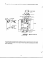
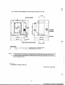
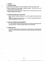
The figure below shows an example stand-alone inverter its
panel
componentldevice
and
layout.
--SIDE PANEL
Surround the direct current reactor with ventilation duct fixed on the panel as shown in the figure
to optimal coolingof the direct current reactor. The front face
of the surrounding cover may
be
used to install a relay.
6
,/-
3.3 ENCLOSURE TYPES
NEMA TYPE 1 GENERAL-PURPOSE INDOOR enclosures are intended for use indoors,
primarily to prevent accidental contact of personnel with the enclosed equipment, in areas where
unusual service conditions do not exist.
-
-
-
-
NEMA TYPE 2 DRIPPROOF INDOOR enclosures are intended for use indoors to protect
the enclosed equipment against
falling noncorrosive liquids and falling dirt.
-
-
NEMA TYPE3 DUSlTlGHT, RAINTIGHT AND SLEET-RESISTANT (ICE-RESISTANT)
OUTDOOR enclosures are intended for use outdoors
to protect the enclosed equipment against
wind-blown dust and water.
NEMATYPE3R- RAINPROOF ANDSLEET-RESISTANT(1CE-RESISTANT)-OUTDOOR
enclosures are intended for use outdoors to protect the enclosed equipment against rain and
of sleet (ice)will not damage the enclosure and
its
constructed so the accumulation and melting
external mechanisms.
-
NEMA TYPE4 -WATERTIGHT AND DUSmlGHT INDOOR AND OUTDOORenclosures
are intended for use indoors or outdoors to protect the enclosed equipment against splashing
water, seepage of water, falling or hose-directed water, and severe external condensation.
NEMATYPE4X- WATERTIGHT, DUSlTlGHTAND CORROSION-RESISTANT- INDOOR
4 enclosures and,in addition,
AND OUT-DOOR enclosures have the same provisions as Type
are corrosion-resistant.
,/--
-
-
-
NEMA TYPE 12 INDUSTRIAL USE DUSTTIGHT AND DRIPTIGHT INDOOR enclosures are intended for use indoors to protect the enclosed equipment against fibers, flyings, li
dust and dirt, and light splashing, seepage, dripping and external condensation
of noncorrosive
liquids.
-
-
NEMA TYPE 13 OILTIGHT AND DUSTTIGHT INDOOR enclosures are intended for use
indoors primarily to house pilot devices such as limit switches, foot switches, pushbuttons,
selector switches, pilot lights, etc., and to protect these devices against lint and dust, seepage,
external condensation, and sprayingof water, oil or coolant.
Conversion of NEMA Type Numberto IEC Classification Designations
NEMA Enclosure Type Number
I
I
I
and
~
~~
~
1 P10
2
1P11
3
1P54
3R
1 P14
3s
1P54
~
~
~
~
~~
~
1
1P56
4X
4
~~~
IECEnclosureClassificationDesignation
1
5
1P52
6 and 6P
I
I
I
1 P67
~~
1P52
12K12 and
13
NOTE:
1 P54
@ This comparison is based on tests specifiedin IEC Publication 529.
a Can not be used to convert IEC classification designations to NEMA Type
numbers.
,n
Y
8
'
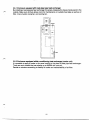
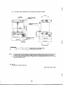
3.4 SELECTION OF THE CORRECT SEE NEMA 1 (EQUIVALENT TO IP-10)
ENCLOSURE FOR THE CORRESPONDING INVERTER CHASSIS UNIT
Question : How can I calculate enclosure size, if I want to mount an open MELTRAC-A
Series inverter chassis unit in my own NEMA
1 enclosure?
Answer
: It is----
a) For selecting the correct size forced ventilationfan on the topof enclosure,
in the controller.
calculate watts loss and required ventilation air volume
KW x 3413
1.085 (LAT-EAT)
=
Required Ventilation Air Volume (CFM)
OR
KW x 860
17.28 (t2- t,)
Required Ventilation Air Volume (m3/min.)
=
LAT : Leading Air Temperature ( O F ) or t, ("C)
EAT : Entrance Air Temperature (OF) or t, ("C)
KW : Heat losses (KW) of all equipment installed inside enclosure
b) DC filter choke prefers
to be placed above inverter unit location where is the
forced ventilation air path.
A wind velocity of 5 meterskec (0.003 miledsec) should be designed to
pass through DC filter choke.
In this case, there should be the space of 8 inches between the DCfilter
choke and the top of the inverter chassis unit.
c) TO.W
. N
E
M
Acode,the inverter panel must have
1. Fuse Disconnect (or circuit breaker)
2. StarVStop pushbutton
Therefore in selecting proper enclosure, assume the customer use circuit
breaker (or fuse + disconnect), starVstop pushbutton, contactor and etc.
~
,,,A*-'
>/
;
I
D0h)T
--- .
I)
-
TRlhJIk
_-
-.
. .. .
0U.L
l.0 r r 2 F i
2) L B k g
Rr,q'o
-.
..--..
.
l,qu
5i-nn+70r3-
2
[5
T-I4(-5
5 P
70
3
Wl
F U % E Q
c/d
a/:
/flus->-
7
~--
pwvw/<
(215
p(5-c
(5
vc/z d E LSIT-Mfh'
30
I'
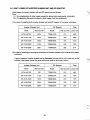
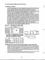
3.5 DUST-PROTECTED ENCLOSURE DESIGN GUIDELINES
When the inverter chassis unit and DC Reactor of MELTRAC
.A is stored in the closed, dustpreventivetypepanel,theheat-radiatingareaandapproximatenaturalradiatingsurface
dimensions required are shownin Table 1.
Table 1 Heat-radiating areaof closed, dust-preventive type control panel
I
I
Closed, dust-preventive
type
(IP5X)
Area required
Model of
Loss radiated
for heat
Approx. natural radiating
Inverter Chassis Unit/DCL in me pawl
radiation
surface dimensions(mm)
(W)
(m2)
. .
I
I
I MT-A140- 75K
I
1
1
MT-A140-220K
I MT-A140-280K
I l75MH175A
675
I
I
6750
8590
210
11.3
1
I
I
112.5
143.2
3.6
I 1200W X lWOD X2300H
I
19300W X 1000D
2300H
X
I 850W X 850D X 850H
T50MH270A
245
4.1
9OOW X 900D X 900H
a:
T36MH350A
270
4.5
95OW X 950DX 950H
T25MH530A
530
8.8
135OW X 1350DX 1350H
T16MH672A
580
9.6
1390W X 1390D X 1390H
8
Q,
8
NOTE
I
.=.&VI FIU I 1 I
lthe panel
I 24800W X 1000D X 2300H I
$
c
1
I
I
DC
Reactor
wholly
stored in
the panel
1. IP5X--- IEC Publication 52G
2. The brake unit is not included.
3. The values in the table are different depending on the operational conditions and
ambient temperature.
(Heat generation at any other place except the inverter
is not taken into consideration.)
4. The values in the table show
the areas which are effective for heat radiation.
5. When the heat radiation fins are outside the panel, theloss shows the heat which is
generated to inside the panel of the inverter unit.
6 . Since the panel dimensions are the values gained when the surrounding
of the whole
if any
(including the ceiling area) is free,
it is necessaryto separately investigate them
side is blocked by the row panel, etc.
7.In addition to the size of the panel which stores DC Reactor is finally necessary to
determine the panel dimensions with the heat radiating area taken into consideration.
10
,n
W
/4
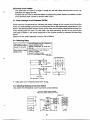
3.5.1 Enclosure equipped with heatpipe type heat exchanger
By installing a heat pipe type heat exchanger for panels, dissipate the losses toinside
the panel
outside.Makesurestructureallowsroomformaintenanceonoutsideheatpipe
as wellasair
filter, inner-inverter cooling fan, and cooling fan.
lTi
I
1
I
Intake
I
I
I
L
3.5.2 Enclosure equipped with air conditioning heat exchanger (cooler unit)
It is possible to apply a cooler unit for panel cooling in the place
of heat pipe heat exchanger.
There are such models that can exhaust up
to with one unit.
2000W
Decide on structure according to reliability of cooler and maintainability
of air filter.
11
3.6 HEAT LOSSES OF INVERTER CHASSIS UNIT AND DC REACTOR
Watt losses of inverter chassis unit and
DC reactor areas follows:
Note:
(1) No consideration of other losses except for above both equipmentsis included.
(2) On designing the panel enclosure, other losses must be considered.
DC reactor in the panel enclosure.
(1)ln case of installing both inverter chassis unit and
I
I
I
I
Inverter Chassis Unit
Reactor
DC
Model
Watt loss (lN)
Model
MT-A140-75K
2250
T75MH175A
210
2460
MT-A140-11OK
3375
T50MH270A
245
3620
MT-A140-150K
MT-A140-220K
MT-A140-280K
I
I
I
I
I
4500
6750
I
8591
T36MH350A
T25MH530A
T16MH672A
Total
Watt loss (W) Losses (W)
I
I
270
530
I
580
I
1
I
4770
7279
9171
I
I
I
(2)In case of installing the cooling
fin of heat sink of inverter chassis unit at outside of the panel
enclosure.
A part of losses of inverter chassis unitis dissipated through the
fin of it's heat sink to the
outside. Heat losses inside the panel enclosure shall be as shown below:
DC Reactor
Inverter Chassis Unit
Total
Watt loss (W) Losses (W)
Model
Watt loss (W)
Model
MT-A140-75K
750
T75MH175A
210
960
MT-A140-11OK
1125
T50MH270A
245
1370
MT-A140-150K
1500
T36MH350A
270
1n
o
MT-A140-220K
2250
T25MH530A
530
2780
MT-A140-280K
2860
T16MH672A
580
3157
12
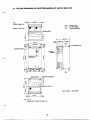
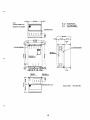
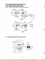
3.7 OUTLINE DRAWINGS OF INVERTER CHASSIS UNIT AND DC REACTOR
Fig. 1
inverter Chassis Unit
R, S, T : Power Source
Pl, P
P, N
Model MT-Ala-75K
: DC FilterReactor
: Dynamic Breaking
(14.17)
172 (6.77)
M(14.17)
368 (14.01)
P1
P
R
S
T
I 1
u
v
I I
w
on a::n
on a::n
on a:z:n
Approxweight
12
(0.471)"
-
12
a(1323)
)"
-(om
Unit : mm, kg
where Number in bracket is inches, Us.
40kg (88LBs)
Fig. 2 DC Reactor
Model l75MHl75A for Inverter chassis unit Model MT-Al40-75K
0
+
(10.2)
NOTE 1)
2)
I
260
Air outlet
Q
Terminals of
Temprature
sensor (M4)
\
\
A
-8.
275 (IO.@\
lO(0.4)
The accMnpanying DC Filter (Reactor) is manufacturedwith the conditionthat it mustbe aircooled (air volume of
4 - 5dsec. blown) from forced ventilath. Please consider the aircooUng structure based on this condition.
DC Filter is equipped with temperalure
s e n s o r . Please connect itto the auxiliarysignal input terminal with normally
open (NO) contact W A , 125V.
Unit :mm.kg
where Number in bracket is Inches,LBs.
I
I
Approxweight22kg
14
(49LBs)
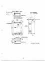
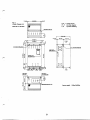
Fig. 3 Inverter Chassis
Unit
R, S, T : Power Source
P1, P : DC Filter Reactor
P, N : Dynamic Breaking
Model MT-Ala-110K
r-
Sa, (14.17)
(5.47)
1m
(7.72)
.
'
r-
.
I
r
c
t
E
I
u
jj
v
//
:!
w
/j
i!
Approx weight 67kg (148LBs)
15
Fig. 4 DC Reactor Model T50MH270A for InverterChassis Unit Model MT-Al40-110K
4 holes for Fixing Bolts
k
260 (10.24)
NOTE 1)
2)
\
0
0
10 (0.39)
/I-
The accompanyingDC Filter (Reactor)is manufacturedwith the condition thatit must beaircooled (air volumeof
4 5dsec. blown) fromforced ventilation. Please consider the aircooling structure based on this condition.
DC Filter is equipped with temperature sensor. Please connect
R to the auxiliary signal input terminal with normally
open (NO) contact OBA, 125V.
-
Unit : mm. kg
where Number in bracket is Inches, LBs.
Approx weight 30kg
16
(66LBs)
,
I
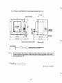
Fig. 5 Inverter Chassis
Unit
R, S, T : Power Source
P1, P : DC Filter Reactor
P, N : Dynamic Breaking
Model MT-A140-150K
lrsbl
I L
bl
bl I44
J
r
Approx weight 67kg
I:
h
17
(1 48LBs)
Fig. 6 DC Reactor Model T36MH350A for Inverter Chassis UnitModel MT-Al40-150K
0
4 holes for Rdng B
o
b
k
280 (11.02)
NOTE 1)
2)
\
\
10 (0.39)
4 -
Cable Connection terminals (M12 Bolts)
0
Forced ventilation
The accompanying DC Filter (Reactor)is manufactured with thecondition that it must beaircooled (air volume of
4 - 5m/sec. blown) from forced ventilation. Please consider
the air-cooling structure based on this condition.
DC Filter is equipped with temperature sensor. Please connectit to the auxiliary signal input terminal with normally
open (NO) contact 0.6A, 125V.
Unit : mm. kg
where Number in bracket is Inches, LBs.
Approxweight36kg
18
(79LBs)
I
.,
(0.47) 12
..
474 (l8.W)
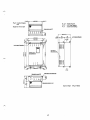
Fig. 7
R, S, T : Power Source
P1, P : DC Filter Reactor
P, N : Dynamic Breaking
Model MT-Al40-220K
Approx weight
19
115kg (254LBs)
Fig. 8 DC Reactor M o d e l T25MH530A for Inverter Chassis Unit Model MT-Al40-220K
4 holea for Fixing W t s
(M12 Bob)
c)
Air outlet
Terminals of
Temperature
sensor (M4)
230 (9.06)
20 (0.79)
m m
SO(12.60)
0Forced Ventilatingc )
NOTE 1)
2)
The accompanyingDC Filter (Reactor) is manufactured with the condition that
it must beaircooled (air volume of
4 5m/sec.blown) from forced ventilation.
Please consider thea i r d i n g structure based on this condition.
DC Filter is equipped with temperature sensor.
Please connect it to the auxiliary signal input terminal with normally
open (NO)contact 0.6A, 125V.
-
Unit : mm. kg
where Number in bracket is Inches, U s .
Approx weight 42kg
(93LBs)
Y
20
t
Fig. 9
Inverter chas~isUnit
R, S, T : Power Source
P i , P : DC FilterReactor
P, N : DynamicBreaking
Model MT-Ai40-280K
u
v
w
Approx weight
21
i s k g (342LBs)
Rg. 10 DC Reactor Model T16MH672A for Inverter Chassis Unit Model MT-Al40-280K
4 holes for Fixing Bolts
(M12 Bolts)
I
2)
Air outlet
0
375 (14.77)
\Rating plate
NOTE 1)
0
0Forced Ventilationcr
The accompanying DC Filter (Reactor)is manufactured withthe condiion that it must be aircooled (air volumeof
4 Bdsec. blown) fromforced ventilation. please considerthe a i r d i n g structure basad on this condition.
DC Filter is equipped with temperature sensor.Please connect it to the auxiliary signal input terminal with normally
open (NO) contact 0.6A, 125V.
-
Unit : mm. kg
where Number in bracket is Inches, LBs.
Approx weight 50kg (11OLBs)
22
r
4. PRECAUTIONS ON DESIGNING INVERTER PANELS
4.1 PRECAUTIONS ON DESIGNING CIRCUITS
(1)The circuit breaker installed on the input side of the inverter should be provided with a shunt
trip device (SHT).To ensure safety, turnoff this circuit breakerif the inverter stops operation
to protect the devices.
If a magnetic contactor
is provided on the input side
of the inverter, also turn
off the magnetic
contactor for the same situation and reason as for the circuit breaker.
(2)A magnetic contactoris not necessarily provided on the input side
of the inverter. However,
if providing oneso as not to apply power to the main circuit for safety reasons during inverter
stop, the operating sequence with respect to the inverter should be as follows.
(a)Time t l from picking up
of input contactor(88) to starting inverter operation
is the time for
checking that the DC voltage (the capacitor charge voltage) has reached the specified
level. (tl = approximately 1 second)
(b)Make sure that the input magnetic contactor
off inturns
0.5 second after the inverter stops.
off before
It is not preferable that the input magnetic contactor has
turned the inverter stops.
(3)Contactors 88L1, 8812 and 88H are necessary to install a backup circuit operating on the
commercial power line.
(a)Be sure to mechanically and electrically interlock commercial line contactor (88H) and
inverter output contactor (88L2) so that these two contactors will not turn on simultaneously. If the commercial line power
is applied to the input terminals
of the inverter from
88H through 8 8 1 2 , the inverter will be damaged.
(b)When switching from the operation on the commercial power
to the
lineoperation on the
88L1 to apply power to the inverter input terminals.
inverter power line, first turn on
When theDC voltage is established (takes approximately one second),offturn
88H. Then
(8812). This sequenceis to avoid a rush charge current
turn on inverter output contactor
from flowing into the inverter.
23
(c) When changing from the operation on the inverter power line to the operation on the
commercial power line, the inverter then 88L2 are to be turned off. Then, wait until the
residual motor voltage disappear (approximately three seconds) before turning
on
88H.
At this stage, voltage drop in the power source due to the start-up current
and false
be checked.
operation of the thermal relays (fans) should
(4)lf a protective functionis activated, do not reset the system from the remote panel.
Otherwise, the cause of thefailure will not be known. If the accident is critical but the cause
is not known,it may worsen.
(5)When stopping the motor then restarting
it while the motoris still running freely, the restart
function on the commercial power line of the inverter is activated to subsidize the free run first.
The inverter then accelerates the motor.
(6)The input and output signals
in the inverter control circuit are designed
to operate under direct
current 24 volts. Refer page12 for the specificationsof the control devices. Check thecoil
current and the minimum contact current
of the relaysto be used for selection.
(7)lnstall the exhaust fan circuit. Refer to "LIST
OF PERIPHERALS"for the leading particulars
of the exhaust fan.
(8)It is recommended that the control power should remain on even when the main circuit power
is off. Otherwise, when a protective function
is activated the control circuit power
is turned off
turned off. This makes investigation on the cause
at the same time as the main ircuit ispower
of failure difficult.Or, it is difficult to check the control circuit operation without turning on the
main circuit.
(9)The frequency setting signal circuit uses micro current. Install micro signal contacts
in this
circuit to ensure sound contact.
(IO)Install a ground fault relay,
if used, on the inverter power line. The ground fault relay should
be capableof handling high harmonics and surge created by the inverter.
I
Q ,'
L'
;
(1 1) If thyristors are installed
in the same power line iforthe line voltage fluctuates
3 % or more,
install anAC reactor (optional).
(12) If afluorescence lampis installedin the inverter panel, install a SparkSuppressor
(CR50500,
made by Okaya) at the terminals of the fluorescence lamp.
24
!
'
f
"
4.2 PRECAUTIONS ON DESIGNING CONSTRUCTION
(1)lnstall the inverterat the lower sectionof the inverter panel. Install the direct current reactor
abovetheinverter,This is to ensurethatfreshaircoming in throughthebottom of theinverter
panel cools the inverter first.
(2)Forced-cool the direct current reactor
at an air velocity of approximately
5 m/sec.
(3)Do not install the inverter panel
in a dusty environment. Otherwise, dust causes poor contact,
short circuit, deterioration
in insulationwhen dust contains moisture and reduction
in cooling
air flow and subsequent insufficient cooling by clogged filter.
(4)lf the inverter panel should be installed in a dusty environment, install the inverter heat
radiation fins and direct current reactor outside the panel. Make the panel fully-closed.
Use
a heat pipe cooling device
to remove heat. Make sure that the inverter heat radiation fins are
accessible and removable to facilitate maintenance and repair.
(5)If the inverter panel
is installed in an environment where corrosive gases or salt exist, provide
the same precautions described in (4) above. Otherwise, the printed circuit boards and
components are corroded and relays, switches and connectors produce poor electrical
contact.
(6)Lay out the parts and external terminalsso that the main circuit and the control circuit are
completely isolated from the other.
(7) Use shielded cables for the analog, pulse and PLGsosignals
that theywill not be affected by
induction from other signals.
P
(8) When installing the parameter unit on the door of the inverter panel, use the exclusive ca
so that excessive forces will not exerted on the cables to avoid
(optional). Install the cables
them from being disconnected from the parameter unit.
(9)Grounding is one
of the most important
wiringsfor the inverter panel. Provide
a grounding bus
line that can be connected
to grounding cableof 38mm2.
(10) Thecableforthemaincircuit
will befairlylarge in diameter.Determinethedevice
considering the cable routing between the devices and between the devices and external
terminals.
25
____
-.
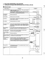
5. SELECTING PERIPHERALS AND OPTIONS
5.1 GUIDELINE FOR SELECTING PERIPHERALS AND OPTIONAL DEVICES
Selection Guide
Name (model)
Installation
Description
Power source capacity Capacity must exceed kVA described In "Power supply Capacitf
standanl specifications(p. 26).
Line-side main
circuit cable
Circuit Breaker
Cooling Fan
AC contactor
AC reactor for power
coordination
Install to prevent inverter malfunction
ifsurge voltageis generated on
or vacuum contactoron the same
power line from a thyristor converter
power system. Also install when the supply voltage imbalance
is
greater than3%.
Radio noise filter
(FR-BIF)
DC reactor forpower
factor improvement
Reactor connecting
xble
Select proper cable size.
Brake unit (MT-BU)anc This brake unit improves inverter braking capability. Use the brake unit
discharge resistor (MT- in combination with a discharge resistor.
BR)
Power regenerative
:onver&er
(available soon)
Use when continuousor high braking capacityis required andwhen
(GW)frequently.
operating and stopping high inerb'al loads
This unit is ahigh-performancebrake unit thatsavesenergyby
to the power source. Unit advantages include
regenerating power back
no need for discharge resistors and significantly cooler operation.
Sine-wave filter
This filter reduces motor noise. The next largest inverter for the motor
rating should be selected.
Load-side main circuit Select proper cable size.
cable
26
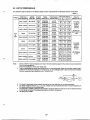
5.2 LIST OF PERIPHERALS
f-
This selection table is based on the standard design motors manufactured by Mitsubishi Electric Corporation
(Note 1).
ldtage
T75MH
175A
75kW
(100HP)
MT-Al40-75K
90kW
(125HP)
MT-Al40-110K
T50MH
(NF400300A)
270A
llOkW (150HP)MT-A14&110K
4OOV
to
460v
132kW
MT-Al40-150K
200kW
W-Al40-m)K
220kW (300HP) MT-A140-mK
250kW(350HP)
W-Al40-280K
NF225225A
(NFZSPSA)
S-K100
(S-K150)
NF225Z?5A
50/60Hz
(192A)
(174A)
(157A)
60
(S-K180)
(130A)(140A)(160A)
60
60
60
60
80
80
Suction
port,
100
T50MH
270A
(NFm WA)
(s-mo)
T36MH
W
AI
NF400400A
(NF400W A )
S-Kl80
(230A)(235A)(282A)
100
100
(S-K220) 100
T?,$f
NF400 400A
(NF600600A)
S-K400
(348A)
(375A)
(426A)
(S-K400)
2x100 2x100 2x100
NF600 5ooA
(NFBOO600A)
S-K400
(S-KWO)
NF225225A
T16MH
NF-600 600A
(NF600600A)
672A
S-K180
(190A)
(205A)
(233A)
80
PF-25ASD
lolwllov
12&/min
3mmAg
500 X 500mm or
20d/min
4mmAg
(383A) (410A) (470A) Suction Port,
2x100 2x100 2x100 500X 500mm
or more
(533A)
S-K600
(435A)
(460A)
(S-K600)
2x100
2x100
2x125
Notes 1. Motors of 75kW or more are basically custom-made. Their characteristics depend on the of
number
poles, the protection
form, and the manufacturer.
Check the specifications of the motor actually used.
2. Types in parentheses are applied when devices are run on commercial power. Select
an interruption capacity thatis
suitable for the short-circuit capacity
of the power source.To use a leakage breaker, select one that accommodates
harmonic surgesand has a sensitivity currentof 100 to 500 mA.
3. The model in parentheses is the contactor to be usedon the motor side when run on commercial power.
be selected than listed in this table depending on
4. For cables outside the panel(R, S , T, U, V, and W), a larger size may
the cabling conditions
and the cabling distance.
5. An exhaust fan is needed to discharge heat generated
in the panel. Select a fan that
can provide an adequate exhaust
air flow taking into account the pressure
loss caused by the fitter at the inlet port.
6. HP rating is only at 48OV.
5.3 No-Fuse Breakers (NFBs) and input Circuit Fuses
r7
(1)Protective coordination
The NFBis used to protect the wiring from damage caused by overload and short-circuit
any accidental current passing the inverter input circuit,
currents. Install the NFB tooffshut
such as overload and short-circuit, and minimize the influence
of the accident.
Select the NFB of which interrupting capacity
is appropriate for the estimated short-circuit
current in the circuit according to the overall impedance of the power supply. (For full
information, refer to the Mitsubishi no-fuse breaker technical information.)
The master NFB and inverter NFB must
be fully coordinated for protection. Should a lowif the transistors in the inverter circuitof the
impedance short circuit occur, for example,
inverter are damaged or the diodes
in the converter circuit are broken, the master NFB may
be tripped. Hence,it is necessary to make precheck using the operational characteristic
curve. Use of a fast acting fuse for semiconductor element protection allows the coordination rangeto be expanded by a current limiting effect. (For more information on the fuse,
see Table5.3.1.) When the overall impedance of the power supply line is small, the peak
value of the inverter input power supply increases. Therefore, the current peak value must
be reducedby the current limiting actionof the power-factor correcting reactor.
Therefore, the MT-A series is designed to attach a power factor improving direct current
reactor to the direct current circuit as standardized attachment.
Table. 5.3.1 Fast Acting Fuse Selection Table
Fuse Rating
Inverter Model
Rated current n-I
MT-A140-75K FLG-500
200
MT-A140-110K
300
MT-A140-150K
MT-A140-220K
MT-A140-280K
I
I
400
500
600
capecity
Fuse type
X
1OOkA
200
FLG-500 X 500
FLGdOO X 600
* fordetailsoncharacteristicsoffastacting
fuse,referto“MitsubishiSemi-Conductor
Protection Fast Acting Fuse” catalog
(2)Setting the rated current and the interrupting capacity of inverter primary NFB
The NFBin the inverter primary circuit
is used to protect the inverter primary wiring form
overload and short circuit. A large in rush current will not occur on inverter operation.
so that commercial operation for back up is possible, an
However, on a system designed
NFB with large enough rated current must be selected
so that it will not trip at activation
current on commercial operation. Especially when load
GD is large (asin a fan), be sure
to select an NFB with large rated current.
Interrupting capacity should be determined by calculating short-circuit current from system
impedance and capacity of NFB should be larger than the calculated value.
.
I
28
1
5.4 Magnetic Contactor
r"
-
(1)lnverter
primary
magnetic
contactor
(MC)
Theinverterprimarycircuitcanbedirectlyconnectedwiththe
NFB, in somecases,the MC
may be provided for any
of the following purposes.
(a) To prevent an accident caused by automatic restart when the power
is restored after
the inverter has been stopped by a power failure. (When an instantaneous power
failure of 15msecorlongeroccurs,instantaneouspowerfailureprotection
is
activated to prevent the inverter from automatically restarting when the power is
restored. When a power failure
is longer than about50 to lOOmsec, the inverteris
automatically reset when the power
is restored andis therefore restarted automatically if the run signalis on.)
(b)Todisconnecttheinverterfromthepowersupplywhentheinverterprotective
function is activated or when a fault occursin the drive unit (e.g. emergency stop
operation).
(c) To keep the inverter stopped for a long time
The inverter control power supply and cooling fan are always running, consuming a
little power. When the inverter
is kept stopped for a long time, power can be
economized slightly by switching the inverter power supply
off,
(d) To separate the inverter from the power supply
to ensure safety during maintenance
and inspection. Since the inverter primary
MC is used for the above purposes, the
number ofodoff times is extremely small. Select the MC which conforms to Standard
Code JEM1038-AC Class 3in relation to the inverter input current.
Note:The inverter may be run and stopped by switching the MC on and off. However,
frequent start and stop using theMC must be avoided because an inrush current
repeated at power-on reduces the life
of the converter circuit (switching life
is about
200,000 times). Run and stop the inverter by switching on off
and
the inverter start
control terminal (STF, STR).
(2)lnverter secondary magnetic contactor
When a magnetic contactor
is provided between the inverter and motor, do not switch on the
MC during operationin principle. When the MC
is provided for either
of the following purposes,
switch on the MC when both the inverter and motor are at a stop.
(a) To run the motor by switching between the commercial power supply and inverter
In this case, the commercial power supply MC and inverter output circuit MC must
be magnetic contactors with electrical and mechanical interlocks andtwo
theMCs
if the
must be designed not
to turn on at the same time. The transistors are damaaed
commercial power is applied
to the invertero u w t terminals. Select theMC which
has a sufficient capacity for the inverter output current. (JEM1038-AC Class3 or
higher) Take special care
so that the inverteris not connected with the commercial
power supply by an arc generated when the current is shut
off.
(b) To use one inverter with several motors by switching the inverter-driven motors from
one to another. The MC must be switched on when both the inverter and motor are
at a stop. The MC may
be switched off during operation. SelectMC
the
which meets
JEM-1038-AC Class 3 or higher
in consideration of the switching life.
29
5.5 Thermal Relay
A thermal relayis generally used to protect a general-purpose motor. The current flowing
in the
general-purpose motor driven from the inverter
is about 10% larger than that flowing
in the motor
driven with the commercial power supply.
For this reason, set the thermal relay
to 1.1 times greater than the current value for use with the
rise ofthemotormayexceedthe
commercialpowersupply.Notethatthetemperature
permissible value even at the load current ofratedvalue
within the
when the motor
is continuously
so that
the load torque
run at the rated torque at low speed. Therefore, select the motor
capacity
is less than the permissible motor torque. The MT-A inverters are incorporated with an electronic
thermal relayto protect the motor from overload
in the low speed range.
When several motors are operated by one inverter or when a special motor is operated, the
operational characteristic
of the electronic thermal relay cannot
be coordinated with the overload
thermal characteristic of the motor. Therefore, provide a thermal relay
in this case.
5.6 Cable Size and Wiring Distance
(1)Main circuit cables
Like that of a general power cable, determine the size ofcircuit
the main
cable after examining
its current capacrty, shortcircuit protection and cable voltage drop. The effectiveof value
the
inverter primary current must be noted because a current larger than the motor overload
current may flow depending on the inverter input power factor.If the wiring distance of the
cable between the inverter and motor is long, a voltage drop increases, causing the motor
torque to be insufficient and the current to increase.
In an extreme case, the motor may be
overheated. Note that especially when the output frequency
is low, the output voltage
of the
inverter is low accordingly and the rate of voltage drop increases.
Select the cable size so that the voltage drop between the inverter3%and
motor
is
of the
rated
voltage.
The line voltage drop can be calculated by the following expression:
Line voltage drop M
6 x cable resistance[ W m ] x wiring distance [m] x current [A]
=
1,000
Use a larger cable diameter when the wiring distance is long or it is desired to decrease the
voltage drop in the low speed range (torque reduction).
When it is desired
largeruse
ato
diametercablebut it cannotbeconnected directly with the motor and
inverter terminals, provide relay terminal boxes as shown below:
Intermediateterminal b o x
I
power
Standard cable
Large cable
Standard cable
!
Wiring length to the motor
When the wiring distance between the inverter and motor
is long, overcurrent protection may
I
be activated by the influence
of the charging current (leakage current)
to the
duestray capacity
of the wiringin additionto the aforementioned voltage drop. Hence, the wiring length should
be 500m maximum. (When several motors are connected, the overall length should be within
1000m)
When primary magnetic flux control has been selected, the cable length should be within 30m.
A longer cable length may cause instable rotation at low inspeed,
addition to reduced torque.
30
i
/4
-
(2)Control circuit cables
The cable size of 0.75mm2 or largeris enough for use with other than the main circuit, e.g.
operation
signal
circuits.
and
Abrakewire of 0.75m isrecommendedforin-panelwiringwhendirectlyconnected
to brake
circuit terminal base. (screw for terminal baseM3.)
is
5.7 Earth-Leakage Circuit Breakers (ELCBs)
Since harmonic components are included in the output voltage
of the inverter which drives the
motor, an earth leakage current occurs continuously due
to the electrostatic capacitanceto the
earth in the electrical path from the inverter
to the motor and the stray capacitance between the
motor winding and iron core. For this reason, the rated sensitivity current of the ground fault
interrupter installed in the power supply side of the inverter should be selected as described
below:
Select unit with rated response current 100
at to 500mA.
5.8 Selecting Relay
Use small signaltype (twin contacts)to
prevent defective contact.
Tateishi: model G2A, Fuji: model473,
Relay used for input
STF and STR, b r a e
circuits
2, and 5.
A74 ntc
I
US0 Small relayOf under 1OOmA Of
DC12V or DC24V.
Be sure to attach bv diode.
Omrom: G2A-432Ab, G2R-l-SD, etc.
I
Type G2A-432A-D
28.5 or less
1.8
42.5 01 less
5.4
Take care not to mistake polarity when wiring.
5.9 Selecting Braking Circuit Input Switch
Use switch for infinitesimal current
to prevent contact defects.
Example of switch (Nippon Kaiheiki)
Paddle Locker Switch (M-2012J-G-W1 W)
12.2
-1
31
5.10 Selecting the Frequency Setting Potentiometer
(1)Type: WMWYA2SEBKl WZ (Japan Resistor)
Wound variable resistor 2W1
kB&2 characteristic
(2)Type: RVJ4MAT1 WKLB specially made(Tokyo Kosumosu)
413.6hole
410 hole
(Unit : mm)
U
25.4 or more
RVJ4NAT
5.1 1 Frequency Setting Device Name Plate and Dial
Nameplate
Control
1-
*I
8
e l 0 hole
-
I
I t -
'
"
1
,n
\
32
T-
5.12 Selecting the Frequency Meter and Calibration Resistor
The manual controller with frequency meter (such as the FR-AX) is available. When only a
frequencymeter is installedseparately,usetheinstrumentofthefollowingspecifications:
Moving-coil DC ammeter
Full scale 1mA (internal resistance30022 ma.)
Graduations: 60, 120, 240Hz in full scale.
Alternatively, graduatein rpm accordingto the number of poles of the motor used.
Frequencymeter
[Example] (1)Connecting between FM and SD
Type: YM206G, 1mA, BKO-C1529H74
Graduations: 0 to 65, 130Hz, double graduations
2 W . 5 acrew (torf
ibng)
[Example] (2)Connecting between AM and 5
Type: YM-8
8
I
0 Graduations C-75HZ
0 0.5mAcoil
0 Frame color N1.5
0 Fined up the resistance fully adjustablefrom
DCBV to 12v
Panel holes
33
Scale calibration resistor
Frequency scale terminal FM of inverter generates maximum approximatelySVDC. Thus,
calibrate scale by using the below specified variable resistor. This is not necessary when
calibration is conducted by applying parameter unit.
Scale calibration resistor over 1/3W
1O k n
(Example)
Type: RV24YN, 20SB1Om-K (Tokyo Kosumosu)
Carbon film type variable resistor,
1/3W 1OWZB characteristic
3
2.5
Panel holes
I
5.13 Selection of Twist wire and Shield wire
(Example) Twist wire
Type: KV-2C x 0.35Q (Daiichi Denko)
Number of
Conductor poles, size
(mm')
I
2x0.3
1
Finished
exterior
perimeter
(mm)
2x0.3
Characteristicsof one electric wire
1
1aO.18
I
Under64.4
1
300
1
60
I
ReWhite
(Example) Multicore shield wire
Type: VCT-S3C x 0.55Q (Jyoban Densen)
Number of
poles, size
(mm')
Characteristics of one electric wire
Finished
exterior
Structure
Rated
perimeter
(poledmm)
voltage
(V)
(mm)
8.3 3x0.3 2010.18
600
-
34
f
-
Color
Grey
w..
,
,.,.. . ,..--.-..-._
.
.-. . ..
.
.
..*. _.. .. -
,.. ., .
.
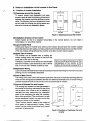
6. Notes on Installationof the Inverter in the Panel
7-
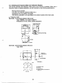
6.1 Position of Inverter Installation
(1)Clearances around the inverter
To ensure proper heat dissipation and easy
access, leave at least the following dimensions
between the inverter and other devices or panel
walls. The following minimum dimensions must
be left under the inverter
as wining space and
above the inverteras dissipation space.
(sideview)
(Front view)
Fig.6.1.1 Clearances around the Inverter
(2)lnstallation directionof the inverter
Install inverter so that it is situated horizontally in the normal fashion.
horizontally orin any other manner.
Do not install it
(3)Layout Inside Panel
Inside panel layout of inverter and direct current reactor should have the inverter situated
below the direct current reactor,
so that sucked in air from bottom of panel can cool the inver
(This also makes wiring between the inverter and direct current reactor easier.)
(4)Upper Part of Inverter
Theinverterunit is installed with a cooling fan
inside, making heatin the inverter to rise from the
lower partof the unit to the top.
Set surrounding temperature
so that
Therefore, if another unit or device is to be situated
temperatureatfansuctionatthe
above the inverter, such should be a unit or device
bottom of the inverteris below 50°C.
that is immune from defects caused by heat.
~~~
~
(5)Separation Wiring
Layout of parts and external terminals should besoplanned
that wiring for the main circuit and
braking circuitis completely separated.
(6)Lead of Main Circuit
will become quite thick. Be sure to check the bending of
radius
The wiringof the main circuit
wires and the wiring layout between devices and external terminals prior to actual wiring to
prevent excessive force to buld on the main circuit terminal
of inverter.
(7)hyout of Exhaust Fan and Inverter
The cooling fan causes the heat generatedin
the inverter to flow from the bottom oftothetop
unit as warm wind. When a fan is installed to
' \,
ventilatetheheat,determinetheinstallation
place of the ventilating fan after full considerInverter
Inverter
ation of the wind flow. (The wind flows in a path
that
where resistance is small. Lay parts so
out
cooling air blows on the inverter.)
*Direct current reactor needs to be cooled at
2
windspeed of approximately5m/sec.Direct
current can be cooled by exhaust fan
if placed
wind duct of exhaust fan.
Fig.6.1.2 Positions of Ventilation Fan and
Inverter
tt
1.
35
I
r
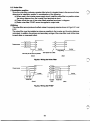
6.2 Noise filter
(1)lnstallation position
Since the noise filter produces a greater effect
it is located
when closer to the source
of noise,
determine its installation positionin consideration of the following:
(a) When used
in the inverter power supply circuit, install the noise
in a filter
position where
the wiring distance from the inverter input terminals
is short.
(b)There shouldbe over 4 line-noise filters serializedas shown in diagram.
(c) Radio noise filterFR-BIF cannot beapplied to output side.
(2)Wiring
The noise filter cannot produce
its effect unlessit is properly wired as shown in 6.2.1
Fig.sand
6.2.2.
The noise filter must
be installed as close as
possible to the inverter andits wiring distance
minimized. In addition, the primary and secondary wirings
of the noise filter must not be close
to each other or
cross each other.
Eachphesehasafilter.
Fig.6.2.1 Wiring the Noise F i b
R
Power swrce
S
T
R
R
S
S
T
T
+ Inverter
Inverter
FR-BIF
. '
Y
Fig.6.2.2 Wiringthe FR-BIF
i
36
1
1
i
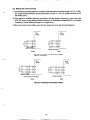
6.3 Wiring the control circuit
,/--
(1) Use twistedor shielded cables for connection with the control circuit terminals
(10,2,5,4, AM).
Do not ground the shield but connect
it as shownin Fig.6.3.1 or 6.3.2. (Keep the otherend of
the shieldopen.)
(2)Use twistedor shielded cables for connection with the display (frequency) meter terminals
(FM, SD) over a wiring distanceof 200m maximum.If the distance exceeds 200m, the display
(frequency) meter reading may result
in a larger error.
(3)Run the control circuit cables
away from the power line over the shortest distance.
MT-A
inverter
MT-A
inverter
Wrong connection
( W
Fig.6.3.1 Connecting the Shielded Cables
MT-A
inverter
\
Fit the terminal for shielding.
(Good)
Fig.6.3.2 Connecting the ShieldedCables
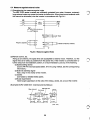
6.4 Measures against external noise
(1)Strengthening the measures against noise
The MELTMC series inverters are sufficiently protected from noise. However, extremely
large external noise may cause the inverter
to malfunction. When there
is such external noise
that cannot be eliminated, wirethe inverter in accordance with Fig.6.4.1.
, I
. _ _$1_5_ -
indicator)
(Frequency
4'
Indicator
Fig.6.4.1 Measures against Noise
(2)Remote control, etc.
Acting as an antenna, the signal lines are susceptible to external noise. Therefore, run the
If the inverter is controlled 30m or
signal linesas far away as possible from the power line.
further away fromits installation position,it is recommended to use any of the following:
(a) Speed setting device
Use the FR-FK motorized speed setter. (For the using method,
see the corresponding
information.)
(b) External starVstop signal
Add a relayin the vicinity of the inverter.
(c) Cables
Use twisted or twisted shield cables.
(d)Surge suppressors
Install surge suppressorsto the coilsof the relays, valves, etc. around the inverter.
L
i
[Example] DCR2-12003-5041 (manufactured by Matsuo)
Blue vinyl cord
I
Red vinyl cord
Vinyl cover
/
38
i
1
7. TESTING
/A
... -
7.1 CHECKING
WIRING
(1)Checkthewiringthoroughlyforincorrectconnections
in themainandcontrolcircuits.
(2)Check the connectors for poor contact or insufficient insertion. Check that the main and
control circuits do not touch each other.
(3)Check that the grounding has been done correctly.
Be sure to correctly ground the inverter
also before testing in the workshop.
7.2 DIELECTRIC WITHSTAND VOLTAGE TEST
Perform dielectric withstand voltage test on the circuits except for the inverter control
circuit.
Install jumper straps across terminals
R, S, T, U, V and W to comprehensively perform
dielectric strength test on the main circuit.
7.3 INSULATION RESISTANCE MEASUREMENT
First, make sure that the inverter has been grounded.
500 volt
Useinsulation
a
tester to test
the main circuit only.A 1000 Volt insulation tester is not recommended.
7.4 OPERATION TEST
First, perform a sequence test on the control circuit. Check that the inverter parameter
correct. Turn on the main circuit. Check the motor and other machines for safety. Start
operation.
/--
8. PRECAUTIONS ON INVERTER INSTALLATION AND OPERATION
8.1 INSTALLING INVERTER PANEL
(1) Make the cable between the inverter panel and the motor shortest possible minimize
the impedance between the inverter and the motor.
(2)ln principle, install the inverter
in the electric room.
(3)Check that the environmental conditionscomply with the requirementsdefined
in the
inverter specification.
(4)Be sure to ground the inverter securely.
8 2 EXTERNAL WRING
(1)Separate the main circuit wiring 30ormmore away from the control circuit wiring.
Minimize the distance over which the two circuitsinrun
parallel to each other.
(2)Ground the shield of the shielded cables carrying frequency signals at one point on
the inverter side. If grounded at two points for incoming and outgoing signals,
circulating currents flows
to generate noise. Install the shielded cables
in an independent duct from other control or power lines
in aorsteel conduit.
8.3 GROUNDING INVERTER PANEL
Ground the inverter panel directly to the grounding electrode or grounding bus line
without routing other panels or devices. (Special Class
3 or better). Use the
10 ohm
grounding wireof 38 mm2 or larger.
8.4 MEASURES AGAINST NOISE
Source the inverter operation power from the exclusive transformer.
To reduce
noise, provide a noise suppressor for the relays connected to the operation power
source.
of 22OV or less)...CR50500BI Made by Okaya
(Example of noise suppressor) (circuit
Denki)
If a thyristor control unit withoutis connected
ACL
to the same bus line, add the power
coordination AC reactor (optional).
i
40
r
f
i
c
8.5 CHECKING LINE VOLTAGE
Check that the line voltage
is within the allowable voltage for the inverter.
Also check
that the transient voltage drop immediately after starting other machine or a voltage
drop due to start-up current complies with the above requirement. For a 400 Volt
system, check that the grounding installation is of neutral grounding or isolated
neutral system. Note that one-line grounding
is prohibited by the Electrical Installation Standard.
9. PRECAUTIONS ON OPERATION AND MAINTENANCEOF INVERTERS
(1)Due to electrical chargein the capacitor, the system cannot be started up within one second
after turning on the main power.
(2) Perform dielectric strength test only on the main circuit.
not perform
Do
dielectric strength test
on the control circuit.
(3)Do not perform dielectric
test on the inverter.
Be sureto disconnect the cables from
the inverter
before performing dielectric strength test on the cables.
(4)Use a testerto test the control circuit for continuity. Do not use the dielectric strength tester
or buzzer instead.
(5)FOr some time after turning off the inverter power, the capacitor has been chargedto high
off indicating that
potential. Before accessing the main circuit, check that the chargeislamp
the capacitor has been discharged, and also check that the voltage
across
P and N
in the main
30 V.
circuit is no greater than DC
(6)Set the acceleration and deceleration times to be longer than commercial acceleration or
natural deceleration times, respectively.
(7)Even in handling a small load,
do not connect the motor the rated capacity of which exceeds
that of the inverter.
(8)When using a radio communications equipment, close the inverter cover or the door on the
panel.
(9)Do not connect a phase advancing capacitor in the load circuit
of the inverter.
(10) Check that the connectors, screws and nuts are securely fastened.
41
0'
I
:
AMlTSUBlSHl ELECTRIC C0RPORATK)N
HEAD OFFICE : MlTSUBlSHl DENKI BLffi., MARUNOUCHI, TOKYO 1 0 0 . TELEX-: J24532 CABLE : MELCO TOKYO
TELEX : 7523-97 MELCO J
NAGASAKI WORKS : 6 1 4 MARUO-MACHI, NAGASAKI,JAPAN TEL (OSSS). 64.2580