1
EMG2926-Q10A
Dual-Band Wireless AC/N Gigabit Ethernet Gateway
Version 1.00
Edition 1, 03/2014
Quick Start Guide
User’s Guide
Default Login Details
LAN IP Address
http://192.168.0.1
(Router Mode)
www.zyxel.com
User Name
admin
Password
(blank)
Copyright © 2014 ZyXEL Communications Corporation
IMPORTANT!
READ CAREFULLY BEFORE USE.
KEEP THIS GUIDE FOR FUTURE REFERENCE.
Screenshots and graphics in this book may differ slightly from your product due to differences in
your product firmware or your computer operating system. Every effort has been made to ensure
that the information in this manual is accurate.
Related Documentation
• Quick Start Guide
The Quick Start Guide shows how to connect the EMG2926-Q10A. It contains information on
setting up your network and configuring for Internet access.
EMG2926-Q10A User’s Guide
2
Contents Overview
Contents Overview
User’s Guide .......................................................................................................................................10
Introduction ............................................................................................................................................. 11
Introducing the Web Configurator ...........................................................................................................17
Connection Wizard ..................................................................................................................................20
Easy Mode ..............................................................................................................................................30
Router Mode ...........................................................................................................................................41
Tutorials ..................................................................................................................................................48
Technical Reference ..........................................................................................................................60
Monitor ....................................................................................................................................................61
WAN ........................................................................................................................................................66
Wireless LAN ..........................................................................................................................................74
LAN .........................................................................................................................................................92
DHCP Server ..........................................................................................................................................95
NAT .........................................................................................................................................................99
DDNS ....................................................................................................................................................106
Static Route ...........................................................................................................................................107
Firewall .................................................................................................................................................. 110
Content Filtering .................................................................................................................................... 114
Parental Controls .................................................................................................................................. 116
IPv6 Firewall ..........................................................................................................................................121
StreamBoost Management ...................................................................................................................124
Remote Management ............................................................................................................................129
Universal Plug-and-Play (UPnP) ...........................................................................................................134
USB Media Sharing ...............................................................................................................................136
Port Configuration .................................................................................................................................145
Maintenance ..........................................................................................................................................147
Troubleshooting ....................................................................................................................................156
EMG2926-Q10A User’s Guide
3
Table of Contents
Table of Contents
Contents Overview ..............................................................................................................................3
Table of Contents .................................................................................................................................4
Part I: User’s Guide ......................................................................................... 10
Chapter 1
Introduction......................................................................................................................................... 11
1.1 Overview ........................................................................................................................................... 11
1.1.1 Dual-Band ................................................................................................................................12
1.2 Applications .......................................................................................................................................12
1.3 Ways to Manage the EMG2926-Q10A ..............................................................................................12
1.4 Good Habits for Managing the EMG2926-Q10A ...............................................................................13
1.5 Resetting the EMG2926-Q10A .........................................................................................................13
1.5.1 How to Use the RESET Button ................................................................................................13
1.6 The WPS Button ...............................................................................................................................13
1.7 LEDs .................................................................................................................................................14
1.8 Wall Mounting ...................................................................................................................................16
Chapter 2
Introducing the Web Configurator ....................................................................................................17
2.1 Overview ...........................................................................................................................................17
2.2 Accessing the Web Configurator .......................................................................................................17
2.2.1 Login Screen ...........................................................................................................................17
2.2.2 Password Screen ....................................................................................................................18
Chapter 3
Connection Wizard .............................................................................................................................20
3.1 Overview ...........................................................................................................................................20
3.2 Accessing the Wizard ........................................................................................................................20
3.3 Connect to Internet ............................................................................................................................21
3.3.1 Connection Type: IPoE ............................................................................................................22
3.3.2 Connection Type: PPPoE ........................................................................................................24
3.4 Router Password ...............................................................................................................................25
3.5 Wireless Security ..............................................................................................................................26
3.5.1 Wireless Security: No Security ................................................................................................26
3.5.2 Wireless Security: WPA2-PSK .................................................................................................27
EMG2926-Q10A User’s Guide
4
Table of Contents
Chapter 4
Easy Mode ...........................................................................................................................................30
4.1 Overview ...........................................................................................................................................30
4.2 Navigation Panel ...............................................................................................................................31
4.3 Network Map .....................................................................................................................................32
4.4 Control Panel ....................................................................................................................................32
4.4.1 Power Saving ..........................................................................................................................33
4.4.2 Parental Controls .....................................................................................................................34
4.4.3 Firewall ....................................................................................................................................35
4.4.4 Internet Settings ......................................................................................................................35
4.4.5 Wireless Security .....................................................................................................................37
4.4.6 WPS ........................................................................................................................................38
4.5 Status Screen in Easy Mode .............................................................................................................39
Chapter 5
Router Mode........................................................................................................................................41
5.1 Overview ...........................................................................................................................................41
5.2 Router Mode Status Screen ..............................................................................................................41
5.2.1 Navigation Panel .....................................................................................................................44
Chapter 6
Tutorials ...............................................................................................................................................48
6.1 Overview ...........................................................................................................................................48
6.2 Set Up a Wireless Network with WPS ...............................................................................................48
6.2.1 Push Button Configuration (PBC) ............................................................................................48
6.2.2 PIN Configuration ....................................................................................................................49
6.3 Configure Wireless Security without WPS ........................................................................................50
6.3.1 Configure Your Notebook ........................................................................................................52
6.4 Using Multiple SSIDs on the EMG2926-Q10A ..................................................................................54
6.4.1 Configuring Security Settings of Multiple SSIDs ......................................................................55
Part II: Technical Reference............................................................................ 60
Chapter 7
Monitor.................................................................................................................................................61
7.1 Overview ...........................................................................................................................................61
7.2 The Log Screen .................................................................................................................................61
7.2.1 View Log ..................................................................................................................................61
7.2.2 Log Setting ..............................................................................................................................62
7.3 DHCP Table
...................................................................................................................................62
7.4 Packet Statistics
.............................................................................................................................63
EMG2926-Q10A User’s Guide
5
Table of Contents
7.5 WLAN Station Status
.....................................................................................................................64
Chapter 8
WAN .....................................................................................................................................................66
8.1 Overview ...........................................................................................................................................66
8.2 Internet Connection ...........................................................................................................................66
8.2.1 IPoE Encapsulation .................................................................................................................66
8.2.2 PPPoE Encapsulation .............................................................................................................69
8.3 Advanced WAN Screen ....................................................................................................................72
Chapter 9
Wireless LAN.......................................................................................................................................74
9.1 Overview ...........................................................................................................................................74
9.2 General Wireless LAN Screen .........................................................................................................74
9.3 Wireless Security ..............................................................................................................................77
9.3.1 No Security ..............................................................................................................................77
9.3.2 WEP Encryption ......................................................................................................................78
9.3.3 WPA-PSK/WPA2-PSK .............................................................................................................79
9.3.4 WPA/WPA2 ..............................................................................................................................80
9.4 More AP Screen ................................................................................................................................82
9.4.1 More AP Edit ...........................................................................................................................83
9.5 MAC Filter Screen ............................................................................................................................85
9.6 Wireless LAN Advanced Screen .......................................................................................................87
9.7 Quality of Service (QoS) Screen .......................................................................................................88
9.8 WPS Screen ......................................................................................................................................88
9.9 WPS Station Screen ..........................................................................................................................90
9.10 Scheduling Screen ..........................................................................................................................90
Chapter 10
LAN ......................................................................................................................................................92
10.1 Overview .........................................................................................................................................92
10.2 LAN IP Screen ................................................................................................................................92
10.3 IP Alias Screen ................................................................................................................................93
10.4 IPv6 LAN Screen .............................................................................................................................94
Chapter 11
DHCP Server .......................................................................................................................................95
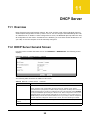
11.1 Overview .........................................................................................................................................95
11.2 DHCP Server General Screen ........................................................................................................95
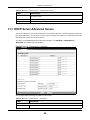
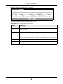
11.3 DHCP Server Advanced Screen
..................................................................................................96
11.4 DHCP Client List Screen .................................................................................................................97
Chapter 12
NAT.......................................................................................................................................................99
EMG2926-Q10A User’s Guide
6
Table of Contents
12.1 Overview
......................................................................................................................................99
12.2 NAT General Screen .....................................................................................................................100
12.3 Port Forwarding Screen ...............................................................................................................100
12.3.1 Port Forwarding Edit Screen ..............................................................................................102
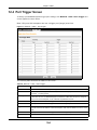
12.4 Port Trigger Screen .......................................................................................................................104
Chapter 13
DDNS..................................................................................................................................................106
13.1 Overview ......................................................................................................................................106
13.2 General
.......................................................................................................................................106
Chapter 14
Static Route .......................................................................................................................................107
14.1 Overview
....................................................................................................................................107
14.2 IP Static Route Screen .................................................................................................................107
14.2.1 Add/Edit Static Route ..........................................................................................................108
Chapter 15
Firewall .............................................................................................................................................. 110
15.1 Overview
..................................................................................................................................... 110
15.2 General Screen ............................................................................................................................ 110
15.3 Services Screen ............................................................................................................................ 111
Chapter 16
Content Filtering ............................................................................................................................... 114
16.1 Overview ....................................................................................................................................... 114
16.2 Content Filter Screen .................................................................................................................... 114
Chapter 17
Parental Controls .............................................................................................................................. 116
17.1 Overview ....................................................................................................................................... 116
17.2 Parental Control Screen ................................................................................................................ 116
17.2.1 Add/Edit a Parental Control Rule ......................................................................................... 117
17.2.2 Add/Edit a Service ............................................................................................................... 119
Chapter 18
IPv6 Firewall ......................................................................................................................................121
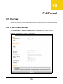
18.1 Overview .......................................................................................................................................121
18.2 IPv6 Firewall Screen ....................................................................................................................121
Chapter 19
StreamBoost Management...............................................................................................................124
19.1 Overview ......................................................................................................................................124
EMG2926-Q10A User’s Guide
7
Table of Contents
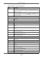
19.2 Network Screen ............................................................................................................................125
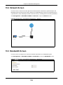
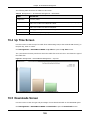
19.3 Bandwidth Screen .........................................................................................................................125
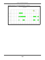
19.4 Up Time Screen ...........................................................................................................................126
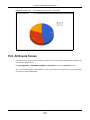
19.5 Downloads Screen .......................................................................................................................126
19.6 All Events Screen .........................................................................................................................127
Chapter 20
Remote Management........................................................................................................................129
20.1 Overview .......................................................................................................................................129
20.2 WWW Screen
.............................................................................................................................129
20.3 SNMP ............................................................................................................................................130
20.4 Wake On LAN Screen ...................................................................................................................132
Chapter 21
Universal Plug-and-Play (UPnP)......................................................................................................134
21.1 Overview ......................................................................................................................................134
21.2 UPnP Screen ...............................................................................................................................134
Chapter 22
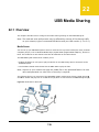
USB Media Sharing...........................................................................................................................136
22.1 Overview .......................................................................................................................................136
22.2 DLNA Screen ................................................................................................................................137
22.3 SAMBA Screen .............................................................................................................................138
22.4 FTP Screen ...................................................................................................................................140
22.5 Example of Accessing Your Shared Files From a Computer ........................................................141
22.5.1 Use Windows Explorer to Share Files .................................................................................141
22.5.2 Use FTP to Share Files .......................................................................................................143
Chapter 23
Port Configuration ............................................................................................................................145
23.1 Overview .......................................................................................................................................145
23.2 Port Configuration Screen .............................................................................................................145
Chapter 24
Maintenance ......................................................................................................................................147
24.1 Overview .......................................................................................................................................147
24.2 General Screen .............................................................................................................................147
24.3 Account Screen .............................................................................................................................147
24.3.1 Edit a User’s Account ..........................................................................................................148
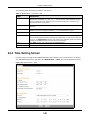
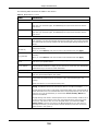
24.4 Time Setting Screen ......................................................................................................................149
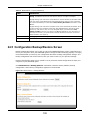
24.5 Configuration Backup/Restore Screen ..........................................................................................151
24.6 Restart Screen ..............................................................................................................................152
24.7 Language Screen ..........................................................................................................................152
EMG2926-Q10A User’s Guide
8
Table of Contents
24.8 System Operation Mode Overview ...............................................................................................153
24.9 Sys OP Mode Screen ....................................................................................................................154
Chapter 25
Troubleshooting................................................................................................................................156
25.1 Overview .......................................................................................................................................156
25.2 Power, Hardware Connections, and LEDs ....................................................................................156
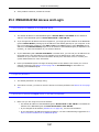
25.3 EMG2926-Q10A Access and Login ..............................................................................................157
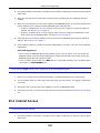
25.4 Internet Access .............................................................................................................................158
25.5 Resetting the EMG2926-Q10A to Its Factory Defaults .................................................................160
25.6 Wireless Connections ...................................................................................................................160
25.7 USB Device Problems ...................................................................................................................162
Appendix A Legal Information..........................................................................................................163
EMG2926-Q10A User’s Guide
9
P ART I
User’s Guide
10
C HAPT ER
1
Introduction
1.1 Overview
This chapter introduces the main features and applications of the EMG2926-Q10A.
The EMG2926-Q10A extends the range of your existing wired network without additional wiring,
providing easy network access to mobile users. You can set up a wireless network with other IEEE
802.11a/ac/b/g/n compatible devices.
A range of services such as a firewall and content filtering are also available for secure Internet
computing. The EMG2926-Q10A also supports the new StreamBoost technology, which is smart
Quality of Service (QoS), to redistribute traffic over the EMG2926-Q10A for the best possible
performance in a home network.
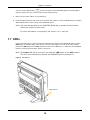
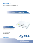
There are two USB 2.0 ports on the side panel of your EMG2926-Q10A. You can connect USB
(version 2.0 or lower) memory sticks, USB hard drives, or USB devices for file sharing. The
EMG2926-Q10A automatically detects the USB devices.
Two USB eject buttons are located above the USB ports. Push the eject button of the corresponding
USB port for 2 seconds. Make sure the USB LED is off before removing your USB device. This will
remove your USB device safely, preventing file or data loss if it is being transmitted through the
USB device.
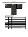
Figure 1 USB Ports and Eject Buttons
Eject buttons
USB ports
Note: For the USB function, it is strongly recommended to use version 2.0 or lower USB
storage devices (such as memory sticks, USB hard drives) and/or USB devices.
Other USB products are not guaranteed to function properly with the EMG2926Q10A.
EMG2926-Q10A User’s Guide
11
Chapter 1 Introduction
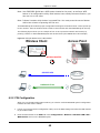
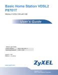
1.1.1 Dual-Band
The EMG2926-Q10A is a dual-band AP and able to function both 2.4G and 5G networks at the same
time. You could use the 2.4 GHz band for regular Internet surfing and downloading while using the
5 GHz band for time sensitive traffic like high-definition video, music, and gaming.
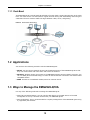
Figure 2 Dual-Band Application
1.2 Applications
You can have the following networks with the EMG2926-Q10A:
• Wired. You can connect network devices via the Ethernet ports of the EMG2926-Q10A so that
they can communicate with each other and access the Internet.
• Wireless. Wireless clients can connect to the EMG2926-Q10A to access network resources. You
can use WPS (Wi-Fi Protected Setup) to create an instant network connection with another WPScompatible device.
• WAN. Connect to a broadband modem/router for Internet access.
1.3 Ways to Manage the EMG2926-Q10A
Use any of the following methods to manage the EMG2926-Q10A.
• WPS (Wi-Fi Protected Setup). You can use the WPS button or the WPS section of the Web
Configurator to set up a wireless network with your EMG2926-Q10A.
• Web Configurator. This is recommended for everyday management of the EMG2926-Q10A using
a (supported) web browser.
EMG2926-Q10A User’s Guide
12
Chapter 1 Introduction
1.4 Good Habits for Managing the EMG2926-Q10A
Do the following things regularly to make the EMG2926-Q10A more secure and to manage the
EMG2926-Q10A more effectively.
• Change the password. Use a password that’s not easy to guess and that consists of different
types of characters, such as numbers and letters.
• Write down the password and put it in a safe place.
• Back up the configuration (and make sure you know how to restore it). Restoring an earlier
working configuration may be useful if the device becomes unstable or even crashes. If you
forget your password, you will have to reset the EMG2926-Q10A to its factory default settings. If
you backed up an earlier configuration file, you would not have to totally re-configure the
EMG2926-Q10A. You could simply restore your last configuration.
1.5 Resetting the EMG2926-Q10A
If you forget your password or IP address, or you cannot access the Web Configurator, you will need
to use the RESET button at the back of the EMG2926-Q10A to reload the factory-default
configuration file. This means that you will lose all configurations that you had previously saved, the
user name will be reset to “admin” and the IP address will be reset to “192.168.0.1”. The default
password is an empty string.
1.5.1 How to Use the RESET Button
1
Make sure the power LED is on.
2
Press the RESET button for one to four seconds to restart/reboot the EMG2926-Q10A.
3
Press the RESET button for longer than five seconds to set the EMG2926-Q10A back to its factorydefault configurations.
1.6 The WPS Button
Your EMG2926-Q10A supports Wi-Fi Protected Setup (WPS), which is an easy way to set up a
secure wireless network. WPS is an industry standard specification, defined by the Wi-Fi Alliance.
WPS allows you to quickly set up a wireless network with strong security, without having to
configure security settings manually. Each WPS connection works between two devices. Both
devices must support WPS (check each device’s documentation to make sure).
Depending on the devices you have, you can either press a button (on the device itself, or in its
configuration utility) or enter a PIN (a unique Personal Identification Number that allows one device
to authenticate the other) on each of the two devices. When WPS is activated on a device, it has
two minutes to find another device that also has WPS activated. Then, the two devices connect and
set up a secure network by themselves.
EMG2926-Q10A User’s Guide
13
Chapter 1 Introduction
You can use the WPS button (
) on the front panel of the EMG2926-Q10A to activate WPS in
order to quickly set up a wireless network with strong security.
1
Make sure the power LED is on (not blinking).
2
Press the WPS button for more than three seconds and release it. Press the WPS button on another
WPS-enabled device within range of the EMG2926-Q10A.
Note: You must activate WPS on the EMG2926-Q10A and on another wireless device
within two minutes of each other.
For more information on using WPS, see Section 6.2 on page 48.
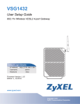
1.7 LEDs
Look at the LED lights on the front panel to determine the status of the EMG2926-Q10A. Use the
LED button at the side panel of the device to turn the LED lights on or off. If you have already
pushed the LED button to the ON position but none of the LEDS are on, make sure the EMG2926Q10A is receiving power and the power is turned on.
Note: The Power LED will be on even if you push the LED button to the OFF position.
This is for you to determine whether the EMG2926-Q10A is powered on.
Figure 3 LED Button
LED button
EMG2926-Q10A User’s Guide
14
Chapter 1 Introduction
Figure 4 Front Panel
Power
Internet
WLAN 2.4G
WLAN 5G
WAN
WPS
Button
USB 1-2
LAN 1-4
WPS
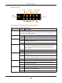
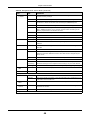
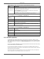
The following table describes the LEDs and the WPS button.
Table 1 Front panel LEDs and WPS button
LED
STATUS
WPS Button
Press this button for 1 second to set up a wireless connection via WiFi Protected Setup
with another WPS-enabled client. You must press the WPS button on the client side within
120 seconds for a successful connection. See Section 1.6 on page 13 and Section 6.2 on
page 48 for more information on WPS.
Power
WAN
Internet
DESCRIPTION
On
The EMG2926-Q10A is receiving power and functioning properly.
Off
The EMG2926-Q10A is not receiving power.
On
The EMG2926-Q10A’s WAN connection is ready.
Blinking
The EMG2926-Q10A is sending/receiving data through the WAN with a
1000Mbps transmission rate.
Off
The WAN connection is not ready, or has failed.
On
The EMG2926-Q10A has an IP connection but no traffic.
Your device has a WAN IP address (either static or assigned by a DHCP
server), PPP negotiation was successfully completed (if used) and the
connection is up.
WLAN 2.4/5G
Blinking
The EMG2926-Q10A is sending or receiving IP traffic.
Off
The EMG2926-Q10A does not have an IP connection.
On
The EMG2926-Q10A is ready, but is not sending/receiving data through the
5G wireless LAN.
Blinking
The EMG2926-Q10A is sending/receiving data through the 5G wireless LAN.
The EMG2926-Q10A is negotiating a WPS connection with a wireless client.
LAN 1-4
USB 1-2
Off
The wireless LAN is not ready or has failed.
On
The EMG2926-Q10A’s LAN connection is ready.
Blinking
The EMG2926-Q10A is sending/receiving data through the LAN with a
1000Mbps transmission rate.
Off
The LAN connection is not ready, or has failed.
On
The EMG2926-Q10A has a USB device installed.
Blinking
The EMG2926-Q10A is transmitting and/or receiving data from routers
through an installed USB device.
Off
There is no USB device connected to the EMG2926-Q10A.
EMG2926-Q10A User’s Guide
15
Chapter 1 Introduction
1.8 Wall Mounting
You may need screw anchors if mounting on a concrete or brick wall.
Table 2 Wall Mounting Information
Distance between holes
12.7 cm
M4 Screws
Two
Screw anchors (optional)
Two
1
Select a position free of obstructions on a wall strong enough to hold the weight of the device.
2
Mark two holes on the wall at the appropriate distance apart for the screws.
Be careful to avoid damaging pipes or cables located inside the wall
when drilling holes for the screws.
3
If using screw anchors, drill two holes for the screw anchors into the wall. Push the anchors into the
full depth of the holes, then insert the screws into the anchors. Do not insert the screws all the way
in - leave a small gap of about 0.5 cm.
If not using screw anchors, use a screwdriver to insert the screws into the wall. Do not insert the
screws all the way in - leave a gap of about 0.5 cm.
4
Make sure the screws are fastened well enough to hold the weight of the EMG2926-Q10A with the
connection cables.
5
Align the holes on the back of the EMG2926-Q10A with the screws on the wall. Hang the EMG2926Q10A on the screws.
Figure 5 Wall Mounting Example
EMG2926-Q10A User’s Guide
16
C HAPT ER
2
Introducing the Web Configurator
2.1 Overview
This chapter describes how to access the EMG2926-Q10A Web Configurator and provides an
overview of its screens.
The Web Configurator is an HTML-based management interface that allows easy setup and
management of the EMG2926-Q10A via Internet browser. Use Internet Explorer 9.0 and later
versions, Mozilla Firefox 21 and later versions, Safari 6.0 and later versions or Google Chrome 26.0
and later versions. The recommended screen resolution is 1024 by 768 pixels.
In order to use the Web Configurator you need to allow:
• Web browser pop-up windows on your device. Web pop-up blocking is enabled by default in
Windows XP SP (Service Pack) 2.
• JavaScript (enabled by default).
• Java permissions (enabled by default).
2.2 Accessing the Web Configurator
1
Make sure your EMG2926-Q10A hardware is properly connected and prepare your computer or
computer network to connect to the EMG2926-Q10A (refer to the Quick Start Guide).
2
Launch your web browser.
3
The EMG2926-Q10A is in router mode by default. Type "http://192.168.0.1" as the website
address.
If the EMG2926-Q10A is in access point mode, the IP address is 192.168.0.2.
Your computer must be in the same subnet in order to access this website address.
2.2.1 Login Screen
The Web Configurator initially displays the following login screen.
EMG2926-Q10A User’s Guide
17
Chapter 2 Introducing the Web Configurator
Figure 6 Login screen
The following table describes the labels in this screen.
Table 3 Login screen
LABEL
DESCRIPTION
Language
Select the language you want to use to configure the Web Configurator.
User
Type "admin" (default) as the user name. Click Login.
Password
Leave this field blank.
2.2.2 Password Screen
You should see a screen asking you to change your password (highly recommended) as shown
below.
Figure 7 Change Password Screen
EMG2926-Q10A User’s Guide
18
Chapter 2 Introducing the Web Configurator
The following table describes the labels on this screen.
Table 4 Change Password Screen
LABEL
DESCRIPTION
New Password
Type a new password.
Retype to Confirm
Retype the password for confirmation.
Apply
Click Apply to save your changes with the EMG2926-Q10A.
Ignore
Click Ignore if you do not want to change the password this time.
Note: The management session automatically times out when the time period set in the
Administrator Inactivity Timer field expires (default five minutes; go to Chapter
24 on page 147 to change this). Simply log back into the EMG2926-Q10A if this
happens.
EMG2926-Q10A User’s Guide
19
C HAPT ER
3
Connection Wizard
3.1 Overview
This chapter provides information on the wizard setup screens in the Web Configurator.
The Web Configurator’s wizard setup helps you configure your device to access the Internet. Refer
to your ISP for your Internet account information. Leave a field blank if you don’t have that
information.
3.2 Accessing the Wizard
Launch your web browser and type "http://192.168.0.1" as the website address. Type "admin"
(default) as the user name and leave the password field blank. Click Login.
Note: The Web Configurator is set to Easy Mode by default after login. If you are in
Expert Mode, you can click the Easy Mode icon on the upper right corner of any
Web Configurator screen to go to Easy Mode.
Click the eaZy123 icon on the network map screen in Easy Mode. The Wizard screen opens.
Choose your Language and click Connect to Internet.
Figure 8 Welcome
EMG2926-Q10A User’s Guide
20
Chapter 3 Connection Wizard
3.3 Connect to Internet
The EMG2926-Q10A offers two Internet connection types. They are IPoE or PPPoE. The wizard
attempts to detect which WAN connection type you are using.
Figure 9 Detecting your Internet Connection Type
If the wizard does not detect a connection type, you must select one from the drop-down list box.
Check with your ISP to make sure you use the correct type.
Note: If you get an error message, check your hardware connections. Make sure your
Internet connection is up and running.
The following screen depends on your Internet connection type. Enter the details provided by your
Internet Service Provider (ISP) in the fields (if any).
EMG2926-Q10A User’s Guide
21
Chapter 3 Connection Wizard
Figure 10 Internet Connection Type
Your EMG2926-Q10A detects the following Internet Connection types.
Table 5 Internet Connection Types
CONNECTION TYPE
DESCRIPTION
IPoE
Select the IPoE (IP over Ethernet) option when the WAN port is used as a regular
Ethernet.
PPPoE
Select the PPPoE (Point-to-Point Protocol over Ethernet) option for a dial-up
connection.
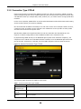
3.3.1 Connection Type: IPoE
Choose IPoE as the Internet Connection Type when the WAN port is used as a regular Ethernet.
Click Next.
EMG2926-Q10A User’s Guide
22
Chapter 3 Connection Wizard
Figure 11 Internet Connection Type: IPoE
The following table describes the labels on this screen.
Table 6 Internet Connection Type: IPoE
LABEL
DESCRIPTION
Internet Connection Type
Select the IPoE option.
Obtain an IP Address
Automatically
Select this radio button if your Internet Service Provider (ISP) did not assign you a
fixed IP address.
Static IP Address
Select this radio button if your ISP assigned an IP address for your Internet
connection.
IP Address
Enter the IP address provided by your ISP.
Subnet Mask
Enter the IP subnet mask in this field.
Gateway IP Address
Enter the gateway IP address in this field.
First DNS Server
Select Obtained From ISP if your ISP dynamically assigns DNS server
information (and the EMG2926-Q10A's WAN IP address). The field to the right
displays the (read-only) DNS server IP address that the ISP assigns.
Second DNS Server
Select User-Defined if you have the IP address of a DNS server. Enter the DNS
server's IP address in the field to the right.
Select None if you do not want to configure DNS servers. If you do not configure
a DNS server, you must know the IP address of a computer in order to access it.
Exit
Click this to close the wizard screen without saving.
Back
Click this to return to the previous screen.
Next
Click this to continue.
Note: If you get an error screen after clicking Next, you might have selected the wrong
Internet Connection type. Click Back, make sure your Internet connection is
working and select the right Connection Type. Contact your ISP if you are not sure
of your Internet Connection type.
EMG2926-Q10A User’s Guide
23
Chapter 3 Connection Wizard
3.3.2 Connection Type: PPPoE
Point-to-Point Protocol over Ethernet (PPPoE) functions as a dial-up connection. PPPoE is an IETF
(Internet Engineering Task Force) standard specifying how a host personal computer interacts with
a broadband modem (for example DSL, cable, wireless, etc.) to achieve access to high-speed data
networks.
For the service provider, PPPoE offers an access and authentication method that works with existing
access control systems (for instance, RADIUS).
One of the benefits of PPPoE is the ability to let end users access one of multiple network services,
a function known as dynamic service selection. This enables the service provider to easily create
and offer new IP services for specific users.
Operationally, PPPoE saves significant effort for both the subscriber and the ISP/carrier, as it
requires no specific configuration of the broadband modem at the subscriber's site.
By implementing PPPoE directly on the EMG2926-Q10A (rather than individual computers), the
computers on the LAN do not need PPPoE software installed, since the EMG2926-Q10A does that
part of the task. Furthermore, with NAT, all of the LAN's computers will have Internet access.
Figure 12 Internet Connection Type: PPPoE
The following table describes the labels on this screen.
Table 7 Internet Connection Type: PPPoE
LABEL
DESCRIPTION
Internet
Connection Type
Select the PPPoE option for a dial-up connection.
Get automatically
from ISP
Select this radio button if your ISP did not assign you a fixed IP address.
Use Fixed IP
Address
Select this radio button, provided by your ISP to give the EMG2926-Q10A a fixed,
unique IP address.
EMG2926-Q10A User’s Guide
24
Chapter 3 Connection Wizard
Table 7 Internet Connection Type: PPPoE (continued)
LABEL
DESCRIPTION
PPP Username
Type the user name given to you by your ISP.
PPP Password
Type the password associated with the user name above.
My WAN IP Address
Type the name of your service provider.
Exit
Click this to close the wizard screen without saving.
Back
Click this to return to the previous screen.
Next
Click this to continue.
The EMG2926-Q10A connects to the Internet.
Figure 13 Connecting to the Internet
Note: If the Wizard successfully connects to the Internet, it proceeds to the next step. If
you get an error message, go back to the previous screen and make sure you have
entered the correct information provided by your ISP.
3.4 Router Password
Change the login password in the following screen. Enter the new password and retype it to
confirm. Click Next to proceed with the Wireless Security screen.
EMG2926-Q10A User’s Guide
25
Chapter 3 Connection Wizard
Figure 14 Router Password
3.5 Wireless Security
Configure Wireless Settings. Configure the wireless network settings on your EMG2926-Q10A on
the following screen. The fields that show up depend on the kind of security you select.
3.5.1 Wireless Security: No Security
Choose No Security on the Wireless Security screen to let wireless devices within range access
your wireless network.
EMG2926-Q10A User’s Guide
26
Chapter 3 Connection Wizard
Figure 15 Wireless Security: No Security
The following table describes the labels on this screen.
Table 8 Wireless Security: No Security
LABEL
DESCRIPTION
Wireless
Network Name
(SSID)
Enter a descriptive name (up to 32 printable 7-bit ASCII characters) for the wireless LAN.
Security Mode
If you change this field on the EMG2926-Q10A, make sure all wireless stations use the same
SSID in order to access the network.
Select a security level from the drop-down list box.
Choose No Security to have no wireless LAN security configured. If you do not enable any
wireless security on your EMG2926-Q10A, your network is accessible to any wireless
networking device that is within range.
Exit
Click this to close the wizard screen without saving.
Back
Click this to return to the previous screen.
Next
Click this to continue.
3.5.2 Wireless Security: WPA2-PSK
Choose WPA2-PSK security in the Wireless Security screen to set up a password for your wireless
network.
EMG2926-Q10A User’s Guide
27
Chapter 3 Connection Wizard
Figure 16 Wireless Security: WPA2-PSK
The following table describes the labels on this screen.
Table 9 Wireless Security: WPA2-PSK
LABEL
DESCRIPTION
Wireless
Network Name
(SSID)
Enter a descriptive name (up to 32 printable 7-bit ASCII characters) for the wireless LAN.
Security Mode
If you change this field on the EMG2926-Q10A, make sure all wireless stations use the
same SSID in order to access the network.
Select a security level from the drop-down list box.
Choose WPA2-PSK security to configure a Pre-Shared Key. Choose this option only if your
wireless clients support WPA2-PSK.
Wireless
password
Type from 8 to 63 case-sensitive ASCII characters. You can set up the most secure wireless
connection by configuring WPA in the wireless LAN screens.
Verify Password
Retype the password to confirm.
Exit
Click this to close the wizard screen without saving.
Back
Click this to return to the previous screen.
Next
Click this to continue.
Congratulations! Open a web browser, such as Internet Explorer, to visit your favourite website.
Note: If you cannot access the Internet when your computer is connected to one of the
EMG2926-Q10A’s LAN ports, check your connections. Then turn the EMG2926Q10A off, wait for a few seconds then turn it back on. If that does not work, log in
to the web configurator again and check if you have typed all information correctly.
See the User’s Guide for more suggestions.
EMG2926-Q10A User’s Guide
28
Chapter 3 Connection Wizard
Figure 17 Congratulations
You can also click GO to open the Easy Mode Web Configurator of your EMG2926-Q10A.
You have successfully set up your EMG2926-Q10A to operate on your network and access the
Internet. You are now ready to connect wirelessly to your EMG2926-Q10A and access the Internet.
EMG2926-Q10A User’s Guide
29
C HAPT ER
4
Easy Mode
4.1 Overview
The Web Configurator is set to Easy Mode by default. You can configure several key features of the
EMG2926-Q10A in this mode. This mode is useful to users who are not fully familiar with some
features that are usually intended for network administrators.
When you log in to the Web Configurator, the following screen opens.
Figure 18 Easy Mode: Network Map
Navigation Panel
Network Map
Go to
Status
Screen
Control Panel
Click Status to open the following screen.
EMG2926-Q10A User’s Guide
30
Chapter 4 Easy Mode
Figure 19 Easy Mode: Status Screen
Navigation Panel
Status Screen
Go to
Network
Map
Screen
Control Panel
4.2 Navigation Panel
Use this navigation panel to opt out of the Easy Mode.
Figure 20 Control Panel
The following table describes the labels on this screen.
Table 10 Control Panel
ITEM
DESCRIPTION
Expert Mode
Click this to change to Expert Mode and customize features of the EMG2926Q10A.
eaZy123
Click this icon to open the setup wizard.
Logout
Click this to end the Web Configurator session and go to the Login page.
EMG2926-Q10A User’s Guide
31
Chapter 4 Easy Mode
4.3 Network Map
When you log into the Web Configurator, the Network Map is shown as follows.
Figure 21 Network Map
You can view the upstream and downstream transmission speeds between the EMG2926-Q10A and
the Internet and/or between the EMG2926-Q10A and the connected device(s) (represented by
icons indicating the kind of network device), including those connecting wirelessly. You can hover
your cursor over a device icon to view details about the device, such as the name, IP address, MAC
address and the device type.
4.4 Control Panel
The features configurable in Easy Mode are shown in the Control Panel.
Figure 22 Control Panel
Switch ON to enable the feature. Otherwise, switch OFF. If the feature is turned on, the green light
flashes. If it is turned off, the red light flashes.
Additionally, click the feature to open a screen where you can edit its settings.
EMG2926-Q10A User’s Guide
32
Chapter 4 Easy Mode
The following table describes the labels on this screen.
Table 11 Control Panel
ITEM
DESCRIPTION
Power Saving
Click this to schedule the wireless feature of the EMG2926-Q10A.
Disabling the wireless function helps lower the energy consumption of the
EMG2926-Q10A.
Switch ON to apply wireless scheduling. Otherwise, switch OFF.
Refer to Section 4.4.1 on page 33 to see this screen.
Parental Control
Click this to restrict access to certain websites, based on keywords contained in
URLs, that you do not want users in your network to open.
Switch ON to apply website filtering. Otherwise, switch OFF.
Refer to Section 4.4.2 on page 34 to see this screen.
Firewall
Switch ON to ensure that your network is protected from Denial of Service (DoS)
attacks. Otherwise, switch OFF.
Refer to Section 4.4.3 on page 35 to see this screen.
Internet Setting
Click this to configure the Internet connection settings.
Refer to Section 4.4.4 on page 35 to see this screen.
Wireless Security
Click this to configure the wireless security, such as SSID, security mode and WPS
key on your EMG2926-Q10A.
Refer to Section 4.4.5 on page 37 to see this screen.
4.4.1 Power Saving
Use this screen to set the day of the week and time of the day when your wireless LAN is turned on
and off. Wireless LAN scheduling is disabled by default. Click the Power Saving icon in the control
panel of the Easy Mode to open the screen shown next.
Disabling the wireless capability lowers the energy consumption of the of the EMG2926-Q10A.
Figure 23 Power Saving
EMG2926-Q10A User’s Guide
33
Chapter 4 Easy Mode
The following table describes the labels on this screen.
Table 12 Power Saving
LABEL
DESCRIPTION
Wireless Radio
Choose whether you want to apply the power saving schedule to 2.4G Hz or 5G Hz
wireless radio.
WLAN Status
Select On or Off to specify whether the Wireless LAN is turned on or off (depending on
what you selected in the WLAN Status field). This field works in conjunction with the
Day and For the following times fields.
Day
Select Everyday or the specific days to turn the Wireless LAN on or off.
If you select Everyday you can not select any specific days. This field works in
conjunction with the For the following times field.
For the following
times (24-Hour
Format)
Select a start time using the first set of hour and minute (min) drop down boxes and
select an end time using the second set of hour and minute (min) drop down boxes. If
you chose On earlier for the WLAN Status the Wireless LAN will turn on between the two
times you enter in these fields. If you chose Off earlier for the WLAN Status the Wireless
LAN will turn off between the two times you enter in these fields.
In this time format, midnight is 00:00 and progresses up to 24:00. For example, 6:00
PM is 18:00.
Apply
Click Apply to save your changes back to the EMG2926-Q10A.
Cancel
Click Cancel to close this screen without saving any changes.
4.4.2 Parental Controls
Use this screen to view the parental control rules configured on the EMG2926-Q10A. Click the
Parental Control icon in the control panel of the Easy Mode to open the screen shown next. See
Chapter 17 on page 116 for how to enable and configure parental control rules.
Figure 24 Parental Control
EMG2926-Q10A User’s Guide
34
Chapter 4 Easy Mode
The following table describes the labels on this screen.
Table 13 Parental Controls
LABEL
DESCRIPTION
Status
This indicates whether the rule is active or not.
A yellow bulb signifies that this rule is active. A gray bulb signifies that this rule is not
active.
Network User
(MAC)
This shows the MAC address of the LAN user’s computer to which this rule applies.
Internet Access
Schedule
This shows the day(s) and time when parental controls are enabled.
Network Service
This shows whether the network service is configured. If not, NONE will be shown.
Website Blocked
This shows whether the website block is configured. If not, NONE will be shown.
4.4.3 Firewall
Enable this feature to protect the network from Denial of Service (DoS) attacks. The EMG2926Q10A blocks repetitive pings from the WAN that can otherwise cause systems to slow down or
hang. Click the Firewall icon in the control panel of the Easy Mode to open the screen shown
next. See Chapter 15 on page 110 for how to enable and configure firewall rules.
Figure 25 Firewall
Click OK to close this screen.
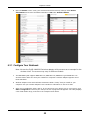
4.4.4 Internet Settings
Use this screen to configure your EMG2926-Q10A for Internet access. You should already have
Internet account information from your ISP. The screen varies depending on the Internet
connection type you selected. Click the Internet Setting icon in the control panel of the Easy
Mode to open the screen shown next.
EMG2926-Q10A User’s Guide
35
Chapter 4 Easy Mode
Figure 26 Internet Setting (IPoE)
Figure 27 Internet Setting (PPPoE)
The following table describes the labels on this screen.
Table 14 Internet Settings
LABEL
DESCRIPTION
Internet
Connection Type
Select the IPoE (IP over Ethernet) option when the WAN port is used as a regular
Ethernet.
Select the PPPoE (Point-to-Point Protocol over Ethernet) option for a dial-up connection.
The following fields are available if you select IPoE.
Obtain an IP
Address
Automatically
Select this radio button if your ISP did not assign you a fixed IP address.
Static IP Address Select this radio button if your ISP assigned an IP address for your Internet connection.
IP Address
Enter the IP address provided by your ISP.
EMG2926-Q10A User’s Guide
36
Chapter 4 Easy Mode
Table 14 Internet Settings (continued)
LABEL
DESCRIPTION
Subnet Mask
Enter the IP subnet mask in this field.
Gateway IP
Address
Enter the gateway IP address in this field.
The following fields are available if you select PPPoE.
Get
automatically
from ISP
Select this radio button if your ISP did not assign you a fixed IP address.
Use Fixed IP
Address
Select this radio button, provided by your ISP to give the EMG2926-Q10A a fixed, unique
IP address.
PPP Username
Type the user name given to you by your ISP.
PPP Password
Type the password associated with the user name above.
My WAN IP
Address
Type the name of your service provider.
Cancel
Click Cancel to close this screen.
Apply
Click Apply to save your changes back to the EMG2926-Q10A.
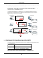
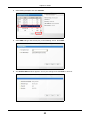
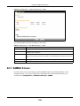
4.4.5 Wireless Security
Use this screen to configure security for your the wireless LAN. You can enter the SSID and select
the wireless security mode in the following screen. Click the Wireless Security icon in the control
panel of the Easy Mode to open the screen shown below.
Note: You can enable the wireless function of your EMG2926-Q10A by first turning on the
switch in the side panel.
Figure 28 Wireless Security
EMG2926-Q10A User’s Guide
37
Chapter 4 Easy Mode
The following table describes the labels on this screen.
Table 15 Wireless Security
LABEL
DESCRIPTION
Wireless Radio
Choose whether you want to apply the wireless security to 2.4G Hz or 5G Hz wireless
radio.
Wireless
Network Name
(SSID)
(Service Set IDentity) The SSID identifies the Service Set with which a wireless station is
associated. Wireless stations associating to the access point (AP) must have the same
SSID. Enter a descriptive name (up to 32 keyboard characters) for the wireless LAN.
Security mode
Select WPA2-PSK to add security on this wireless network. The wireless clients which
want to associate to this network must have same wireless security settings as this device.
After you select to use a security, additional options appear on this screen.
Select No Security to allow any client to connect to this network without authentication.
Wireless
password
This field appears when you choose wither WPA2-PSK as the security mode.
Verify password
Type the password again to confirm.
Apply
Click Apply to save your changes back to the EMG2926-Q10A.
Cancel
Click Cancel to close this screen.
WPS
Click this to configure the WPS screen.
Type a pre-shared key from 8 to 63 case-sensitive keyboard characters.
You can transfer the wireless settings configured here (Wireless Security screen) to
another wireless device that supports WPS.
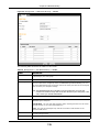
4.4.6 WPS
Use this screen to add a wireless station to the network using WPS. Click WPS in the Wireless
Security screen to open the following screen.
Figure 29 Wireless Security: WPS
EMG2926-Q10A User’s Guide
38
Chapter 4 Easy Mode
The following table describes the labels on this screen.
Table 16 Wireless Security: WPS
LABEL
DESCRIPTION
Wireless Security
Click this to go back to the Wireless Security screen.
WPS
Create a secure wireless network simply by pressing a button.
The EMG2926-Q10A scans for a WPS-enabled device within the range and performs
wireless security information synchronization.
Note: After you click the WPS button on this screen, you have to press a similar button in
the wireless station utility within 2 minutes. To add the second wireless station, you
have to press these buttons on both the EMG2926-Q10A and the wireless station
again after the first 2 minutes.
Register
Create a secure wireless network simply by entering a wireless client's PIN (Personal
Identification Number) in the EMG2926-Q10A’s interface and pushing this button.
Type the same PIN number generated in the wireless station’s utility. Then click Register
to associate the two and perform the wireless security information synchronization.
Exit
Click Exit to close this screen.
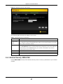
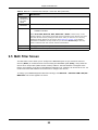
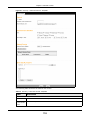
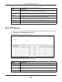
4.5 Status Screen in Easy Mode
In the Network Map screen, click Status to view read-only information about the EMG2926-Q10A.
Figure 30 Status Screen in Easy Mode
The following table describes the labels on this screen.
Table 17 Status Screen in Easy Mode
ITEM
DESCRIPTION
Name
This is the name of the EMG2926-Q10A on the network.
Time
This is the current system date and time.
The date is in YYYY:MM:DD (Year-Month-Day) format. The time is in HH:MM:SS
(Hour:Minutes:Seconds) format.
WAN IP
This is the IP address of the WAN port.
MAC Address
This is the MAC address of the EMG2926-Q10A.
EMG2926-Q10A User’s Guide
39
Chapter 4 Easy Mode
Table 17 Status Screen in Easy Mode (continued)
ITEM
DESCRIPTION
Firmware Version
This shows the firmware version of the EMG2926-Q10A.
The firmware version format shows the trunk version, model code and release
number.
Wireless 2.4G Network
Name (SSID)
This shows the SSID of the wireless network. You can configure this in the Wireless
Security screen (Section 4.4.5 on page 37; Section 9.2 on page 74).
Wireless 5G Network
Name (SSID)
Security
This shows the wireless security used by the EMG2926-Q10A.
EMG2926-Q10A User’s Guide
40
C HAPT ER
5
Router Mode
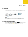
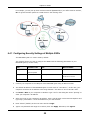
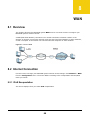
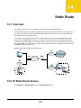
5.1 Overview
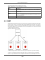
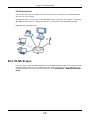
The EMG2926-Q10A is set to router mode by default. Routers are used to connect the local network
to another network (for example, the Internet). In the figure below, the EMG2926-Q10A connects
the local network (LAN1 ~ LAN4) to the Internet.
Figure 31 EMG2926-Q10A Network
Modem
Note: The Status screen is shown after changing to the Expert Mode of the Web
Configurator. It varies depending on the device mode of your EMG2926-Q10A.
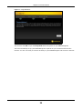
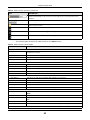
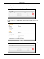
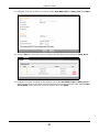
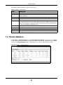
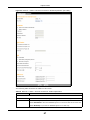
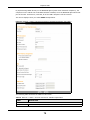
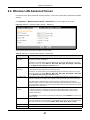
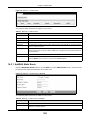
5.2 Router Mode Status Screen
When you are in Easy Mode, click the Expert Mode icon (
) in the upper right corner of
the screen to go to Expert Mode. Click
in Expert Mode to open the status screen.
EMG2926-Q10A User’s Guide
41
Chapter 5 Router Mode
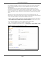
Figure 32 Status Screen: Router Mode
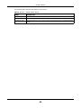
The following table describes the icons shown on the Status screen.
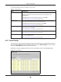
Table 18 Status Screen Icon Key
ICON
DESCRIPTION
Click this at any time to exit the Web Configurator.
Click this icon to view copyright and a link for related product information.
Click this icon to go to Easy Mode. See Chapter 4 on page 30.
EMG2926-Q10A User’s Guide
42
Chapter 5 Router Mode
Table 18 Status Screen Icon Key (continued)
ICON
DESCRIPTION
Select a number of seconds or None from the drop-down list box to refresh all screen
statistics automatically at the end of every time interval or to not refresh the screen
statistics.
Click this button to refresh the status screen statistics.
Click this icon to see the Status page. The information on this screen depends on the
device mode you select.
Click this icon to see the Monitor navigation menu.
Click this icon to see the Configuration navigation menu.
Click this icon to see the Maintenance navigation menu.
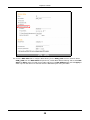
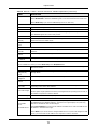
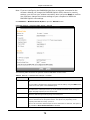
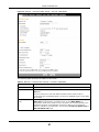
The following table describes the labels shown on the Status screen.
Table 19 Status Screen: Router Mode
LABEL
DESCRIPTION
Device Information
Host Name
This is the System Name you enter in the Maintenance > General screen. It is for
identification purposes.
Model Number
This is the model name of your device.
Firmware Version
This is the firmware version and the date created.
Sys OP Mode
This is the device mode to which the EMG2926-Q10A is set - Router Mode.
WAN Information
MAC Address
This shows the WAN Ethernet adapter MAC Address of your device.
IP Address
This shows the WAN port’s IP address.
IP Subnet Mask
This shows the WAN port’s subnet mask.
Default Gateway
This shows the WAN port’s gateway IP address.
IPv6 Address
This shows the IPv6 address of the EMG2926-Q10A on the WAN.
LAN Information
MAC Address
This shows the LAN Ethernet adapter MAC Address of your device.
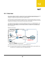
IP Address
This shows the LAN port’s IP address.
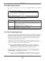
IP Subnet Mask
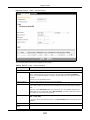
This shows the LAN port’s subnet mask.
DHCP
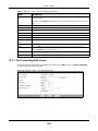
This shows the LAN port’s DHCP role - Server or Disable.
IPv6 Address
This shows the IPv6 address of the EMG2926-Q10A on the LAN.
WLAN 2.4G Information
WLAN OP Mode
This is the device mode to which the EMG2926-Q10A’s wireless LAN is set - Access Point
Mode.
MAC Address
This shows the 2.4GHz wireless adapter MAC Address of your device.
SSID
This shows a descriptive name used to identify the EMG2926-Q10A in the 2.4GHz wireless
LAN.
Channel
This shows the channel number which you select manually.
Security
This shows the level of wireless security the EMG2926-Q10A is using.
WLAN 5G Information
EMG2926-Q10A User’s Guide
43
Chapter 5 Router Mode
Table 19 Status Screen: Router Mode (continued)
LABEL
DESCRIPTION
MAC Address
This shows the 5GHz wireless adapter MAC Address of your device.
SSID
This shows a descriptive name used to identify the EMG2926-Q10A in the 5GHz wireless
LAN.
Channel
This shows the channel number which you select manually.
Security
This shows the level of wireless security the EMG2926-Q10A is using.
Firewall
This shows whether the firewall is enabled or not.
Summary
Packet Statistics
Click Details... to go to the Monitor > Packet Statistics screen (Section 7.4 on page 63).
Use this screen to view port status and packet specific statistics.
WLAN 2.4G Station
Status
Click Details... to go to the Monitor > WLAN 2.4G Station Status screen (Section 7.5 on
page 64). Use this screen to view the wireless stations that are currently associated to the
EMG2926-Q10A’s 2.4GHz wireless LAN.
WLAN 5G Station Status
Click Details... to go to the Monitor > WLAN 5G Station Status screen (Section 7.5 on
page 64). Use this screen to view the wireless stations that are currently associated to the
EMG2926-Q10A’s 5GHz wireless LAN.
System Status
Item
This column shows the type of data the EMG2926-Q10A is recording.
Data
This column shows the actual data recorded by the EMG2926-Q10A.
System Up Time
This is the total time the EMG2926-Q10A has been on.
Current Date/Time
This field displays your EMG2926-Q10A’s present date and time.
System Resource
- CPU Usage
This displays what percentage of the EMG2926-Q10A’s processing ability is currently being
used. When this percentage is close to 100%, the EMG2926-Q10A is running at full load,
and the throughput is not going to improve anymore. If you want some applications to have
more throughput, you should turn off other applications (for example, using bandwidth
management.)
- Memory Usage
This shows what percentage of the heap memory the EMG2926-Q10A is using.
Interface Status
Interface
This displays the EMG2926-Q10A port types. The port types are: WAN, LAN and WLAN.
Status
For the LAN and WAN ports, this field displays Down (line is down) or Up (line is up or
connected).
For the 2.4GHz/5GHz WLAN, it displays Up when the 2.4GHz/5GHz WLAN is enabled or
Down when the 2.4G/5G WLAN is disabled.
Rate
For the LAN ports, this displays the port speed and duplex setting or N/A when the line is
disconnected.
For the WAN port, it displays the port speed and duplex setting if you’re using Ethernet
encapsulation. This field displays N/A when the line is disconnected.
For the 2.4GHz/5GHz WLAN, it displays the maximum transmission rate when the 2.4GHz/
5GHz WLAN is enabled and N/A when the WLAN is disabled.
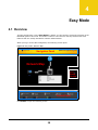
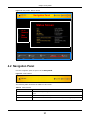
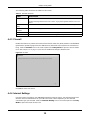
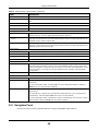
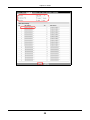
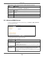
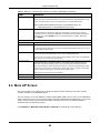
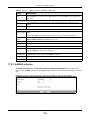
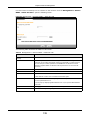
5.2.1 Navigation Panel
Use the sub-menus on the navigation panel to configure EMG2926-Q10A features.
EMG2926-Q10A User’s Guide
44
Chapter 5 Router Mode
Figure 33 Navigation Panel: Router Mode
The following table describes the sub-menus.
Table 20 Navigation Panel: Router Mode
LINK
TAB
Status
FUNCTION
This screen shows the EMG2926-Q10A’s general device, system and
interface status information. Use this screen to access summary statistics
tables.
MONITOR
Log
View Log
Use this screen to view the list of activities recorded by your EMG2926Q10A.
Log Setting
Use this screen to select the logs you wish to display.
DHCP Table
Use this screen to view current DHCP client information.
Packet Statistics
Use this screen to view port status and packet specific statistics.
WLAN 2.4G
Station Status
Association
List
Use this screen to view the wireless stations that are currently associated
to the EMG2926-Q10A’s 2.4GHz wireless LAN.
WLAN 5G
Station Status
Association
List
Use this screen to view the wireless stations that are currently associated
to the EMG2926-Q10A’s 5GHz wireless LAN.
CONFIGURATION
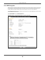
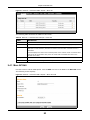
Network
WAN
Internet
Connection
This screen allows you to configure ISP parameters, WAN IP address
assignment, DNS servers and the WAN MAC address.
Advanced
Use this screen to configure other advanced properties.
EMG2926-Q10A User’s Guide
45
Chapter 5 Router Mode
Table 20 Navigation Panel: Router Mode (continued)
LINK
TAB
FUNCTION
General
Use this screen to enable the wireless LAN and configure wireless LAN and
wireless security settings.
More AP
Use this screen to configure multiple BSSs on the EMG2926-Q10A.
MAC Filter
Use the MAC filter screen to configure the EMG2926-Q10A to block access
to devices or block the devices from accessing the EMG2926-Q10A.
Advanced
This screen allows you to configure advanced wireless settings.
QoS
Use this screen to configure Wi-Fi Multimedia Quality of Service (WMM
QoS). WMM QoS allows you to prioritize wireless traffic according to the
delivery requirements of individual services.
WPS
Use this screen to configure WPS.
WPS Station
Use this screen to add a wireless station using WPS.
Scheduling
Use this screen to schedule the times the Wireless LAN is enabled.
IP
Use this screen to configure LAN IP address and subnet mask.
IP Alias
Use this screen to have the EMG2926-Q10A apply IP alias to create LAN
subnets.
IPv6 LAN
Use this screen to configure the IPv6 address for the EMG2926-Q10A on
the LAN.
General
Use this screen to enable the EMG2926-Q10A’s DHCP server.
Advanced
Use this screen to assign IP addresses to specific individual computers
based on their MAC addresses and to have DNS servers assigned by the
DHCP server.
Client List
Use this screen to view information related to your DHCP status.
General
Use this screen to enable NAT.
Port
Forwarding
Use this screen to configure servers behind the EMG2926-Q10A and
forward incoming service requests to the server(s) on your local network.
Port Trigger
Use this screen to change your EMG2926-Q10A’s port triggering settings.
Dynamic
DNS
Dynamic DNS
Use this screen to set up dynamic DNS.
Static Route
Static Route
Use this screen to configure IP static routes.
General
Use this screen to activate/deactivate the firewall.
Services
This screen shows a summary of the IPv4 firewall rules, and allows you to
edit/add an IPv4 firewall rule.
Content Filter
Use this screen to restrict web features and designate a trusted computer.
Wireless LAN
2.4G/5G
LAN
DHCP Server
NAT
Security
Firewall
Content
Filter
Parental
Control
IPv6 firewall
Use this screen to block certain web features and sites containing certain
keywords in the URL.
Services
Use this screen to configure IPv6 firewall rules.
Management
EMG2926-Q10A User’s Guide
46
Chapter 5 Router Mode
Table 20 Navigation Panel: Router Mode (continued)
LINK
TAB
FUNCTION
Network
Use this screen to view transmission data rates between the EMG2926Q10A and the Internet or connected devices.
Bandwidth
Use this screen to configure the maximum allowable bandwidth and enable
automatic updates.
Priorities
Use this screen to change the priority of the connected devices.
Up Time
Use this screen to view the top five traffic flows transmitting to/from the
selected LAN device(s).
Downloads
Use this screen to view the type and percentage of most download traffic.
All Events
Use this screen to view the time at which a traffic flow is given bandwidth
for optimal, good or best-effort performance.
WWW
Use this screen to configure through which interface(s) and from which IP
address(es) users can use HTTP to manage the EMG2926-Q10A.
SNMP
Use this screen to change your EMG2926-Q10A’s SNMP settings.
Wake On LAN
Use this screen to enable Wake on LAN to remotely turn on a device on the
local network.
UPnP
General
Use this screen to enable UPnP on the EMG2926-Q10A.
USB Media
Sharing
DLNA
Use this screen to have the EMG2926-Q10A function as a DLNA-compliant
media server, that lets DLNA-compliant media clients play video, audio, and
photo content files stored on the connected USB storage device.
SAMBA
Use this screen to enable file sharing through the EMG2926-Q10A.
FTP
Use this screen to have the EMG2926-Q10A act as a FTP server.
Streamboost
Management
Remote
Management
Port
Configuration
Use this screen to change the Ethernet port speed and duplex settings.
MAINTENANCE
General
General
Use this screen to view and change administrative settings such as system
and domain names.
Account
Account
Setup
Use this screen to change the password of your EMG2926-Q10A.
Time
Time Setting
Use this screen to change your EMG2926-Q10A’s time and date.
Backup/
Restore
Backup/
Restore
Use this screen to backup and restore the configuration or reset the factory
defaults to your EMG2926-Q10A.
Restart
System
Restart
This screen allows you to reboot the EMG2926-Q10A without turning the
power off.
Language
Language
This screen allows you to select the language you prefer.
Sys OP Mode
Sys OP Mode
This screen allows you to select whether your device acts as a router, or an
access point.
EMG2926-Q10A User’s Guide
47
C HAPT ER
6
Tutorials
6.1 Overview
This chapter provides tutorials for setting up your EMG2926-Q10A.
• Set Up a Wireless Network with WPS
• Configure Wireless Security without WPS
• Using Multiple SSIDs on the EMG2926-Q10A
6.2 Set Up a Wireless Network with WPS
This section gives you an example of how to set up a wireless network using WPS. This example
uses the EMG2926-Q10A as the AP and NWD210N as the wireless client which connects to a
notebook.
Note: The wireless client must be a WPS-aware device (for example, a WPS USB adapter
or PCI card).
There are two WPS methods for creating a secure connection. This tutorial shows you how to do
both.
• Push Button Configuration (PBC) - create a secure wireless network simply by pressing a
button. See Section 6.2.1 on page 48.This is the easier method.
• PIN Configuration - create a secure wireless network simply by entering a wireless client's PIN
(Personal Identification Number) in the EMG2926-Q10A’s interface. See Section 6.2.2 on page
49. This is the more secure method, since one device can authenticate the other.
6.2.1 Push Button Configuration (PBC)
1
Make sure that your EMG2926-Q10A is turned on. Make sure the WIFI button (at the side panel of
the EMG2926-Q10A) is pushed in, and that the device is placed within range of your notebook.
2
Make sure that you have installed the wireless client (this example uses the NWD210N) driver and
utility in your notebook.
3
In the wireless client’s utility, find the WPS settings. Enable WPS and press the WPS button (Start
or WPS button)
4
Log into EMG2926-Q10A’s Web Configurator and press the Push Button in the Configuration >
Network > Wireless LAN 2.4G > WPS Station screen.
EMG2926-Q10A User’s Guide
48
Chapter 6 Tutorials
Note: Your EMG2926-Q10A has a WPS button located on its panel, as well as a WPS
button in its configuration utility. Both buttons have exactly the same function; you
can use one or the other.
Note: It doesn’t matter which button is pressed first. You must press the second button
within two minutes of pressing the first one.
The EMG2926-Q10A sends the proper configuration settings to the wireless client. This may take up
to two minutes. Then the wireless client is able to communicate with the EMG2926-Q10A securely.
The following figure shows you an example of how to set up wireless network and security by
pressing a button on both EMG2926-Q10A and wireless client (the NWD210N in this example).
Figure 34 Example WPS Process: PBC Method
Access Point
Wireless Client
WITHIN 2 MINUTES
SECURITY INFO
COMMUNICATION
6.2.2 PIN Configuration
When you use the PIN configuration method, you need to use both EMG2926-Q10A’s configuration
interface and the client’s utilities.
1
Launch your wireless client’s configuration utility. Go to the WPS settings and select the PIN method
to get a PIN number.
2
Enter the PIN number to the PIN field in the Configuration > Network > Wireless LAN 2.4G >
WPS Station screen on the EMG2926-Q10A.
EMG2926-Q10A User’s Guide
49
Chapter 6 Tutorials
3
Click Start buttons (or button next to the PIN field) on both the wireless client utility screen and the
EMG2926-Q10A’s WPS Station screen within two minutes.
The EMG2926-Q10A authenticates the wireless client and sends the proper configuration settings to
the wireless client. This may take up to two minutes. Then the wireless client is able to
communicate with the EMG2926-Q10A securely.
The following figure shows you an example of how to set up wireless network and security on
EMG2926-Q10A and wireless client (ex. NWD210N in this example) by using the PIN method.
Figure 35 Example WPS Process: PIN Method
Wireless Client
Access Point
WITHIN 2 MINUTES
6.3 Configure Wireless Security without WPS
This example shows you how to configure wireless security settings with the following parameters
on your EMG2926-Q10A.
SSID
SSID_Example3
Channel
6
Security
WPA2-PSK
(Pre-Shared Key: ThisismyWPA-PSKpre-sharedkey)
Follow the steps below to configure the wireless settings on your EMG2926-Q10A.
EMG2926-Q10A User’s Guide
50
Chapter 6 Tutorials
The instructions require that your hardware be connected (see the Quick Start Guide) and that you
be logged into the Web Configurator through your LAN connection (see Section 2.2 on page 17).
1
Make sure the WIFI switch (at the side panel of the EMG2926-Q10A) is set to ON.
2
Open the Configuration > Network > Wireless LAN 2.4G > General screen in the AP’s Web
Configurator.
3
Confirm that the wireless LAN is enabled on the EMG2926-Q10A.
4
Enter SSID_Example3 as the SSID and select Channel-06 as the channel. Set security mode to
WPA2-PSK and enter ThisismyWPA-PSKpre-sharedkey in the Pre-Shared Key field. Click
Apply.
EMG2926-Q10A User’s Guide
51
Chapter 6 Tutorials
5
Open the Status screen. Verify your wireless and wireless security settings under Device
Information and check if the WLAN connection is UP under Interface Status.
6.3.1 Configure Your Notebook
Note: We use the ZyXEL NWD2205 wireless adapter utility screens as an example for the
wireless client. The screens may vary for different models.
1
The EMG2926-Q10A supports IEEE 802.11a, IEEE 802.11b, IEEE 802.11g and IEEE 802.11n
wireless clients. Make sure that your notebook or computer’s wireless adapter supports one of
these standards.
2
Wireless adapters come with software sometimes called a “utility” that you install on your
computer. See your wireless adapter’s User’s Guide for information on how to do that.
3
After you’ve installed the utility, open it. If you cannot see your utility’s icon on your screen, go to
Start > Programs and click on your utility in the list of programs that appears. The utility displays
a list of APs within range, as shown in the example screen below.
EMG2926-Q10A User’s Guide
52
Chapter 6 Tutorials
4
Select SSID_Example3 and click Connect.
5
Select AES and type the security key in the following screen. Click Next.
6
The Confirm Save window appears. Check your settings and click Save to continue.
EMG2926-Q10A User’s Guide
53
Chapter 6 Tutorials
7
Check the status of your wireless connection in the screen below. If your wireless connection is
weak or you have no connection, see the Troubleshooting section of this User’s Guide.
If your connection is successful, open your Internet browser and enter http://www.zyxel.com or the
URL of any other web site in the address bar. If you are able to access the web site, your wireless
connection is successfully configured.
6.4 Using Multiple SSIDs on the EMG2926-Q10A
You can configure more than one SSID on a EMG2926-Q10A. See Section 9.4 on page 82.
This allows you to configure multiple independent wireless networks on the EMG2926-Q10A as if
there were multiple APs (virtual APs). Each virtual AP has its own SSID, wireless security type and
MAC filtering settings. That is, each SSID on the EMG2926-Q10A represents a different access
point/wireless network to wireless clients in the network.
Clients can associate only with the SSIDs for which they have the correct security settings. Clients
using different SSIDs can access the Internet and the wired network behind the EMG2926-Q10A
(such as a printer).
EMG2926-Q10A User’s Guide
54
Chapter 6 Tutorials
For example, you may set up three wireless networks (A, B and C) in your office. A is for workers,
B is for guests and C is specific to a VoIP device in the meeting room.
A
SSID_Worker
C
SSID_VoIP
B
SSID_Guest
6.4.1 Configuring Security Settings of Multiple SSIDs
The EMG2926-Q10A is in router mode by default.
This example shows you how to configure the SSIDs with the following parameters on your
EMG2926-Q10A (in router mode).
SSID
SECURITY TYPE
KEY
MAC FILTERING
SSID_Worker
WPA2-PSK
DoNotStealMyWirelessNetwork
Disable
VoIPOnly12345678
Allow
WPA Compatible
SSID_VoIP
WPA-PSK
00:A0:C5:01:23:45
SSID_Guest
WPA-PSK
keyexample123
Disable
1
Connect your computer to the LAN port of the EMG2926-Q10A using an Ethernet cable.
2
The default IP address of the EMG2926-Q10A in router mode is “192.168.0.1”. In this case, your
computer must have an IP address in the range between “192.168.0.2” and “192.168.0.254”.
3
Click Start > Run on your computer in Windows. Type “cmd” in the dialog box. Enter “ipconfig” to
show your computer’s IP address.
4
After you’ve set up your computer’s IP address, open a web browser such as Internet Explorer and
type “http://192.168.0.1” as the web address in your web browser.
5
Enter “admin” (default) as the user name and click Login.
6
Type a new password and retype it to confirm, then click Apply. Otherwise, click Ignore.
EMG2926-Q10A User’s Guide
55
Chapter 6 Tutorials
7
The Easy Mode appears. Click Expert Mode in the navigation panel.
8
Go to Configuration > Network > Wireless LAN 2.4G > More AP. Click the Edit icon of the first
entry to configure wireless and security settings for SSID_Worker.
9
Configure the screen as follows. In this example, you enable Intra-BSS Traffic for SSID_Worker
to allow wireless clients on the same wireless network to communicate with each other. Click
Apply.
10 Click the Edit icon of the second entry to configure wireless and security settings for SSID_VoIP.
EMG2926-Q10A User’s Guide
56
Chapter 6 Tutorials
11 Configure the screen as follows. You do not enable Intra-BSS Traffic for SSID_VoIP. Click Apply.
12 Click the Edit icon of the third entry to configure wireless and security settings for SSID_Guest.
13 Configure the screen as follows. In this example, you enable Intra-BSS Traffic for SSID_Guest to
allow wireless clients on the same wireless network to communicate with each other. Select Enable
Guest WLAN to allow clients to access the Internet only. Click Apply.
EMG2926-Q10A User’s Guide
57
Chapter 6 Tutorials
14 Click the MAC Filter tab to configure MAC filtering for the SSID_VoIP wireless network. Select
SSID_VoIP from the SSID Select drop-down list, enable MAC address filtering and set the Filter
Action to Allow. Enter the VoIP device’s MAC address in the Mac Address field and click Apply to
allow only the VoIP device to associate with the EMG2926-Q10A using this SSID.
EMG2926-Q10A User’s Guide
58
Chapter 6 Tutorials
EMG2926-Q10A User’s Guide
59
P ART II
Technical Reference
60
C HAPT ER
7
Monitor
7.1 Overview
This chapter discusses read-only information related to the device state of the EMG2926-Q10A.
To access the Monitor screens, go to Expert Mode after login, then click
.
You can also click the links in the Summary table of the Status screen to view the packets sent/
received as well as the status of clients connected to the EMG2926-Q10A.
7.2 The Log Screen
The Web Configurator allows you to look at all of the EMG2926-Q10A’s logs in one location and
select the logs you wish to display.
7.2.1 View Log
Use the View Log screen to see the logged messages for the EMG2926-Q10A. The log wraps
around and deletes the old entries after it fills. Select what logs you want to see from the Display
drop list. The log choices depend on your settings in the Log Setting screen. Click Refresh to
renew the log screen. Click Clear Log to delete all the logs.
Figure 36 View Log
EMG2926-Q10A User’s Guide
61
Chapter 7 Monitor
7.2.2 Log Setting
You can configure which logs to display on the View Log screen. Go to the Log Setting screen and
select the logs you wish to display. Click Apply to save your settings. Click Cancel to start the
screen afresh.
Figure 37 Log Settings
7.3 DHCP Table
DHCP (Dynamic Host Configuration Protocol, RFC 2131 and RFC 2132) allows individual clients to
obtain TCP/IP configuration at start-up from a server. You can configure the EMG2926-Q10A’s LAN
as a DHCP server or disable it. When configured as a server, the EMG2926-Q10A provides the TCP/
IP configuration for the clients. If DHCP service is disabled, you must have another DHCP server on
that network, or else the computer must be manually configured.
Click Monitor > DHCP Table or Configuration > Network > DHCP Server > Client List. Readonly information here relates to your DHCP status. The DHCP table shows current DHCP client
information (including MAC Address, and IP Address) of all network clients using the EMG2926Q10A’s DHCP server.
Figure 38 Monitor > DHCP Table
EMG2926-Q10A User’s Guide
62
Chapter 7 Monitor
The following table describes the labels on this screen.
Table 21 Monitor > DHCP Table
LABEL
DESCRIPTION
#
This is the index number of the host computer.
Status
This field displays whether the connection to the host computer is up (a yellow bulb) or
down (a gray bulb).
Host Name
This field displays the computer’s host name.
IP Address
This field displays the IP address relative to the # field listed above.
MAC Address
This field shows the MAC address of the computer with the name in the Host Name field.
Every Ethernet device has a unique MAC (Media Access Control) address which identifies a
device. The MAC address is assigned at the factory and consists of six pairs of hexadecimal
characters, for example, 00:A0:C5:00:00:02.
Interface
This field shows the interface to which the host computer is connected.
Reserve
Select this if you want to reserve the IP address for this specific MAC address.
Apply
Click Apply to save your changes back to the EMG2926-Q10A.
Cancel
Click Cancel to reload the previous configuration for this screen.
7.4 Packet Statistics
Click Monitor > Packet Statistics or the Packet Statistics (Details...) hyperlink in the Status
screen. Read-only information here includes port status, packet specific statistics and the "system
up time". The Poll Interval(s) field is configurable and is used for refreshing the screen.
Figure 39 Monitor > Packet Statistics
EMG2926-Q10A User’s Guide
63
Chapter 7 Monitor
The following table describes the labels on this screen.
Table 22 Monitor > Packet Statistics
LABEL
DESCRIPTION
Port
This is the EMG2926-Q10A’s interface type.
Status
For the LAN ports, this displays the port speed and duplex setting or Down when the
line is disconnected.
For the WAN port, it displays the port speed and duplex setting if you’re using Ethernet
encapsulation and Idle (line (ppp) idle), Dial (starting to trigger a call) and Drop
(dropping a call) if you're using PPPoE encapsulation. This field displays Down when
the line is disconnected.
For the 2.4GHz or 5GHz WLAN, it displays the maximum transmission rate when the
WLAN is enabled and Down when the WLAN is disabled.
TxPkts
This is the number of transmitted packets on this port.
RxPkts
This is the number of received packets on this port.
Collisions
This is the number of collisions on this port.
Errors
This is the number of received errors on this port.
Tx B/s
This displays the transmission speed in bytes per second on this port.
Rx B/s
This displays the reception speed in bytes per second on this port.
Up Time
This is the total time the EMG2926-Q10A has been on for each session.
System Up Time
This is the total time the EMG2926-Q10A has been on.
Poll Interval(s)
Enter the time interval in seconds for refreshing statistics in this field.
Set Interval
Click this button to apply the new poll interval you entered in the Poll Interval(s)
field.
Stop
Click Stop to stop refreshing statistics.
7.5 WLAN Station Status
Click Monitor > WLAN 2.4G/5G Station Status or the WLAN 2.4G/5G Station Status
(Details...) hyperlink in the Status screen. View the wireless stations that are currently associated
to the EMG2926-Q10A’s 2.4GHz or 5GHz wireless network in the Association List. Association
means that a wireless client (for example, your network or computer with a wireless network card)
has connected successfully to the AP (or wireless router) using the same SSID, channel and
security settings.
Figure 40 Monitor > WLAN Station Status
EMG2926-Q10A User’s Guide
64
Chapter 7 Monitor
The following table describes the labels on this screen.
Table 23 Monitor > WLAN Station Status
LABEL
DESCRIPTION
#
This is the index number of an associated wireless station.
MAC Address
This field displays the MAC address of an associated wireless station.
Association Time
This field displays the time a wireless station first associated with the EMG2926-Q10A’s
WLAN.
EMG2926-Q10A User’s Guide
65
C HAPT ER
8
WAN
8.1 Overview
This chapter discusses the EMG2926-Q10A’s WAN screens. Use these screens to configure your
EMG2926-Q10A for Internet access.
A WAN (Wide Area Network) connection is an outside connection to another network or the
Internet. It connects your private networks such as a LAN (Local Area Network) to other networks,
so that a computer in one location can communicate with computers in other locations.
Figure 41 LAN and WAN
8.2 Internet Connection
Use this screen to change your EMG2926-Q10A’s Internet access settings. Click Network > WAN
from the Configuration menu. The screen differs according to the encapsulation and IPv4/IPv6
mode you choose.
8.2.1 IPoE Encapsulation
This screen displays when you select IPoE encapsulation.
EMG2926-Q10A User’s Guide
66
Chapter 8 WAN
Figure 42 Network > WAN > Internet Connection: IPoE Encapsulation (IPv4 Only)
The following table describes the labels on this screen.
Table 24 Network > WAN > Internet Connection: IPoE Encapsulation
LABEL
DESCRIPTION
ISP Parameters for Internet Access
Encapsulation
You must choose the IPoE option when the WAN port is used as a regular Ethernet.
IPv4 / IPv6
Select IPv4 Only if you want the EMG2926-Q10A to run IPv4 only.
Select Dual Stack to allow the EMG2926-Q10A to run IPv4 and IPv6 at the same time.
Select IPv6 Only if you want the EMG2926-Q10A to run IPv6 only.
EMG2926-Q10A User’s Guide
67
Chapter 8 WAN
Table 24 Network > WAN > Internet Connection: IPoE Encapsulation (continued)
LABEL
DESCRIPTION
IP Address
Obtain an IP
Address
Automatically
Select this option if your ISP did not assign you a fixed IP address. This is the default
selection.
Static IP Address
Select this option if the ISP assigned a fixed IP address.
IP Address
Enter your WAN IP address in this field if you selected Static IP Address.
Subnet Mask
Enter the Subnet Mask in this field.
Gateway IP
Address
Enter a Gateway IP Address (if your ISP gave you one) in this field.
MTU Size
Enter the MTU (Maximum Transmission Unit) size for each packet. If a larger packet
arrives, the EMG2926-Q10A divides it into smaller fragments.
DHCP Option
Enable DHCP Option
121
Select this to enable the classless route option 121.
Enable DHCP Option
125
Select this to add vendor specific information to DHCP requests that the EMG2926Q10A sends to a DHCP server when getting a WAN IP address.
Enable DHCP Option
60
Select this to identify the vendor and functionality of the EMG2926-Q10A in DHCP
requests that the EMG2926-Q10A sends to a DHCP server when getting a WAN IP
address.
Vendor ID
Enter the Vendor Class Identifier (Option 60), such as the type of hardware or
firmware.
6RD
Use IPv6 Rapid Deployment (6rd) when the local network uses IPv6 and the ISP has an IPv4 network. When
the EMG2926-Q10A has an IPv4 WAN address and you set IPv6/IPv4 mode to IPv4 Only, you can enable 6rd
to encapsulate IPv6 packets in IPv4 packets to cross the ISP’s IPv4 network.
The EMG2926-Q10A generates a global IPv6 prefix from its IPv4 WAN address and tunnels IPv6 traffic to the
ISP’s Border Relay router to connect to the native IPv6 Internet. The local network can also use IPv4 services.
The EMG2926-Q10A uses its configured IPv4 WAN IP to route IPv4 traffic to the IPv4 Internet.
This is available only when you select IPv4 Only in the IPv6/IPv4 field.
Enable 6RD
Enable IPv6 rapid deployment to tunnel IPv6 traffic from the local network through the
ISP’s IPv4 network.
Automatically
configured by DHCP
Select this to have the EMG2926-Q10A detect the relay server’s IP address
automatically through DHCP.
Manually Configured
Select this if you have the IPv4 address of the relay server.
Border Relay IPv4
Address
Specify the relay server’s IPv4 address.
Service Provider
IPv6 Prefix
Enter an IPv6 prefix for tunneling IPv6 traffic to the ISP’s Border Relay router and
connecting to the native IPv6 Internet.
Service Provider
IPv6 Prefix length
Enter the IPv6 prefix length.
IPv4 mask length
Enter the subnet mask number (1~32) for the IPv4 network.
An IPv6 prefix length specifies how many most significant bits (starting from the left) in
the address compose the network address.
DNS Server
EMG2926-Q10A User’s Guide
68
Chapter 8 WAN
Table 24 Network > WAN > Internet Connection: IPoE Encapsulation (continued)
LABEL
DESCRIPTION
First DNS Server
Select Obtained From ISP if your ISP dynamically assigns DNS server information
(and the EMG2926-Q10A's WAN IP address). The field to the right displays the (readonly) DNS server IP address that the ISP assigns.
Second DNS Server
Third DNS Server
Select User-Defined if you have the IP address of a DNS server. Enter the DNS
server's IP address in the field to the right.
Select None if you do not want to configure DNS servers. If you do not configure a DNS
server, you must know the IP address of a computer in order to access it.
IPv6 Address
This is not available when you select IPv4 Only in the IPv6/IPv4 field.
Obtain an IP
Address
Automatically
Select this if you want to obtain an IPv6 address from a DHCPv6 server.
Static IP Address
Select this if you have a fixed IPv6 address assigned by your ISP.
IPv6 Address
Enter the IPv6 address assigned by your ISP.
Prefix length
Enter the address prefix length to specify how many most significant bits in an IPv6
address compose the network address.
IPv6 Default
Gateway
Enter the IP address of the next-hop gateway. The gateway is a router or switch on the
same segment as your EMG2926-Q10A's interface(s). The gateway helps forward
packets to their destinations.
IPv6 DNS server
This is not available when you select IPv4 Only in the IPv6/IPv4 field.
Obtain IPv6 DNS
info Automatically
Select this to have the EMG2926-Q10A get the IPv6 DNS server addresses from the ISP
automatically.
Use the following
Static DNS IPv6
Address
Select this to have the EMG2926-Q10A use the IPv6 DNS server addresses you
configure manually.
IPv6 DNS Server
Enter the IPv6 DNS server address assigned by the ISP.
Apply
Click Apply to save your changes back to the EMG2926-Q10A.
Cancel
Click Cancel to begin configuring this screen afresh.
8.2.2 PPPoE Encapsulation
The EMG2926-Q10A supports PPPoE (Point-to-Point Protocol over Ethernet). PPPoE is an IETF
standard (RFC 2516) specifying how a personal computer (PC) interacts with a broadband modem
(DSL, cable, wireless, etc.) connection. The PPP over Ethernet option is for a dial-up connection
using PPPoE.
For the service provider, PPPoE offers an access and authentication method that works with existing
access control systems (for example Radius).
One of the benefits of PPPoE is the ability to let you access one of multiple network services, a
function known as dynamic service selection. This enables the service provider to easily create and
offer new IP services for individuals.
Operationally, PPPoE saves significant effort for both you and the ISP or carrier, as it requires no
specific configuration of the broadband modem at the customer site.
EMG2926-Q10A User’s Guide
69
Chapter 8 WAN
By implementing PPPoE directly on the EMG2926-Q10A (rather than individual computers), the
computers on the LAN do not need PPPoE software installed, since the EMG2926-Q10A does that
part of the task. Furthermore, with NAT, all of the LANs’ computers will have access.
This screen displays when you select PPPoE encapsulation.
Figure 43 Network > WAN > Internet Connection: PPPoE Encapsulation (IPv4 Only)
The following table describes the labels on this screen.
Table 25 Network > WAN > Internet Connection: PPPoE Encapsulation
LABEL
DESCRIPTION
ISP Parameters for Internet Access
Encapsulation
Select PPPoE if you connect to your Internet via dial-up.
EMG2926-Q10A User’s Guide
70
Chapter 8 WAN
Table 25 Network > WAN > Internet Connection: PPPoE Encapsulation (continued)
LABEL
DESCRIPTION
IPv4 / IPv6
Select IPv4 Only if you want the EMG2926-Q10A to run IPv4 only.
Select Dual Stack to allow the EMG2926-Q10A to run IPv4 and IPv6 at the same time.
Select IPv6 Only if you want the EMG2926-Q10A to run IPv6 only.
PPP Information
PPP Username
Type the username given to you by your ISP.
PPP Password
Type the password associated with the username above.
MTU Size
Enter the Maximum Transmission Unit (MTU) or the largest packet size per frame that
your EMG2926-Q10A can receive and process.
PPP Auto Connect
Select this option if you do not want the connection to time out.
Idle Timeout
(second)
This value specifies the time in minutes that elapses before the router automatically
disconnects from the PPPoE server.
PPPoE Service
Name
Enter the PPPoE service name specified in the ISP account.
WAN IP Address Assignment
Get automatically
from ISP
Select this option if your ISP did not assign you a fixed IP address. This is the default
selection.
Use Fixed IP
Address
Select this option if the ISP assigned a fixed IP address.
My WAN IP
Address
Enter your WAN IP address in this field if you selected Use Fixed IP Address.
6RD
This is available only when you select IPv4 Only in the IPv6/IPv4 field.
Enable 6RD
Enable IPv6 rapid deployment to tunnel IPv6 traffic from the local network through the
ISP’s IPv4 network.
Automatically
configured by
DHCP
Select this to have the EMG2926-Q10A detect the relay server IP address automatically
through DHCP.
Manually
Configured
Select this if you have the IPv4 address of the relay server.
Border Relay IPv4
Address
Specify the relay server IPv4 address.
Service Provider
IPv6 Prefix
Enter an IPv6 prefix for tunneling IPv6 traffic to the ISP’s Border Relay router and
connecting to the native IPv6 Internet.
Service Provider
IPv6 Prefix length
Enter the IPv6 prefix length.
IPv4 mask length
Enter the subnet mask number (1~32) for the IPv4 network.
An IPv6 prefix length specifies how many most significant bits (starting from the left) in
the address compose the network address.
DNS Server
First DNS Server
Second DNS
Server
Third DNS Server
Select Obtained From ISP if your ISP dynamically assigns DNS server information (and
the EMG2926-Q10A's WAN IP address). The field to the right displays the (read-only)
DNS server IP address that the ISP assigns.
Select User-Defined if you have the IP address of a DNS server. Enter the DNS server's
IP address in the field to the right.
Select None if you do not want to configure DNS servers. If you do not configure a DNS
server, you must know the IP address of a computer in order to access it.
EMG2926-Q10A User’s Guide
71
Chapter 8 WAN
Table 25 Network > WAN > Internet Connection: PPPoE Encapsulation (continued)
LABEL
DESCRIPTION
IPv6 DNS server
This is not available when you select IPv4 Only in the IPv6/IPv4 field.
Obtain IPv6 DNS
info Automatically
Select this to have the EMG2926-Q10A get the IPv6 DNS server addresses from the ISP
automatically.
Use the following
Static DNS IPv6
Address
Select this to have the EMG2926-Q10A use the IPv6 DNS server addresses you configure
manually.
IPv6 DNS Server
Enter the IPv6 DNS server address assigned by the ISP.
Apply
Click Apply to save your changes back to the EMG2926-Q10A.
Cancel
Click Cancel to begin configuring this screen afresh.
8.3 Advanced WAN Screen
To change your EMG2926-Q10A’s advanced WAN settings, click Network > WAN > Advanced.
The screen appears as shown.
Figure 44 Network > WAN > Advanced
The following table describes the labels on this screen.
Table 26 Network > WAN > Advanced
LABEL
DESCRIPTION
Multicast Setup
Multicast
Select IGMPv1/v2 to enable multicasting. This applies to traffic routed from the
WAN to the LAN.
Select None to disable this feature. This may cause incoming traffic to be dropped or
sent to all connected network devices.
Auto-Subnet Configuration
Enable Auto-IPChange mode
Select this option to have the EMG2926-Q10A change its LAN IP address to 10.0.0.1
or 192.168.0.1 accordingly when the EMG2926-Q10A gets a dynamic WAN IP
address in the same subnet as the LAN IP address 192.168.0.1 or 10.0.0.1.
The NAT, DHCP server and firewall functions on the EMG2926-Q10A are still available
in this mode.
EMG2926-Q10A User’s Guide
72
Chapter 8 WAN
Table 26 Network > WAN > Advanced (continued)
LABEL
DESCRIPTION
Apply
Click Apply to save your changes back to the EMG2926-Q10A.
Cancel
Click Cancel to begin configuring this screen afresh.
EMG2926-Q10A User’s Guide
73
C HAPT ER
9
Wireless LAN
9.1 Overview
This chapter discusses how to configure the wireless network settings in your EMG2926-Q10A. The
EMG2926-Q10A is able to function on both 2.4GHz and 5GHz networks at the same time. You can
have different wireless and wireless security settings for 2.4GHz and 5GHz wireless LANs. Click
Configuration > Network > Wireless LAN 2.4G or Wireless LAN 5G to do so.
See the appendices for more detailed information about wireless networks.
The following figure provides an example of a wireless network.
Figure 45 Example of a Wireless Network
The wireless network is the part in the blue circle. In this wireless network, devices A and B are
called wireless clients. The wireless clients use the access point (AP) to interact with other devices
(such as the printer) or with the Internet. Your EMG2926-Q10A is the AP.
9.2 General Wireless LAN Screen
Use this screen to configure the SSID and wireless security of the wireless LAN.
EMG2926-Q10A User’s Guide
74
Chapter 9 Wireless LAN
Note: If you are configuring the EMG2926-Q10A from a computer connected to the
wireless LAN and you change the EMG2926-Q10A’s SSID, channel or security
settings, you will lose your wireless connection when you press Apply to confirm.
You must then change the wireless settings of your computer to match the
EMG2926-Q10A’s new settings.
Click Network > Wireless LAN 2.4G/5G to open the General screen.
Figure 46 Network > Wireless LAN 2.4G/5G > General
The following table describes the general wireless LAN labels on this screen.
Table 27 Network > Wireless LAN 2.4G/5G > General
LABEL
DESCRIPTION
Wireless LAN
Select Enable to activate the 2.4GHz and/or 5GHz wireless LAN. Select Disable to turn it
off.
You can enable or disable both 2.4GHz and 5GHz wireless LANs by using the WIFI button
located on the side panel of the EMG2926-Q10A.
Name (SSID)
The SSID (Service Set IDentity) identifies the Service Set with which a wireless client is
associated. Enter a descriptive name (up to 32 printable characters found on a typical
English language keyboard) for the wireless LAN.
Hide SSID
Select this check box to hide the SSID in the outgoing beacon frame so a station cannot
obtain the SSID through scanning using a site survey tool.
Channel Selection
Set the operating frequency/channel depending on your particular region.
Select a channel from the drop-down list box. The options vary depending on the
frequency band and the country you are in.
Refer to the Connection Wizard chapter for more information on channels. This option is
only available if Auto Channel Selection is disabled.
EMG2926-Q10A User’s Guide
75
Chapter 9 Wireless LAN
Table 27 Network > Wireless LAN 2.4G/5G > General (continued)
LABEL
DESCRIPTION
Auto Channel
Selection
Select this check box for the EMG2926-Q10A to automatically choose the channel with
the least interference. Deselect this check box if you wish to manually select the channel
using the Channel Selection field.
Operating
Channel
This displays the channel the EMG2926-Q10A is currently using.
Channel Width
Select the wireless channel width used by EMG2926-Q10A.
A standard 20 MHz channel offers transfer speeds of up to 144Mbps (2.4GHz) or 217Mbps
(5GHZ) whereas a 40MHz channel uses two standard channels and offers speeds of up to
300Mbps (2.4GHz) or 450Mbps (5GHZ). An IEEE 802.11ac-specific 80MHz channel offers
speeds of up to 1.3Gbps.
Because not all devices support 40 MHz and/or 80 MHz channels, select Auto 20/40
MHz or Auto 20/40/80 MHz to allow the EMG2926-Q10A to adjust the channel
bandwidth automatically.
40 MHz (channel bonding or dual channel) bonds two adjacent radio channels to increase
throughput. A 80 MHz channel consists of two adjacent 40 MHz channels. The wireless
clients must also support 40 MHz or 80 MHz. It is often better to use the 20 MHz setting
in a location where the environment hinders the wireless signal.
Select 20 MHz if you want to lessen radio interference with other wireless devices in your
neighborhood or the wireless clients do not support channel bonding.
802.11 Mode
If you are in the Wireless LAN 2.4G > General screen, you can select from the
following:
•
•
•
•
•
•
802.11b: allows either IEEE 802.11b or IEEE 802.11g compliant WLAN devices to
associate with the EMG2926-Q10A. In this mode, all wireless devices can only
transmit at the data rates supported by IEEE 802.11b.
802.11g: allows IEEE 802.11g compliant WLAN devices to associate with the Device.
IEEE 802.11b compliant WLAN devices can associate with the EMG2926-Q10A only
when they use the short preamble type.
802.11bg: allows either IEEE 802.11b or IEEE 802.11g compliant WLAN devices to
associate with the EMG2926-Q10A. The EMG2926-Q10A adjusts the transmission rate
automatically according to the wireless standard supported by the wireless devices.
802.11n: allows IEEE 802.11n compliant WLAN devices to associate with the
EMG2926-Q10A. This can increase transmission rates, although IEEE 802.11b or IEEE
802.11g clients will not be able to connect to the EMG2926-Q10A. I
802.11gn: allows either IEEE 802.11g or IEEE 802.11n compliant WLAN devices to
associate with the EMG2926-Q10A. The transmission rate of your EMG2926-Q10A
might be reduced.
802.11 bgn: allows IEEE802.11b, IEEE802.11g and IEEE802.11n compliant WLAN
devices to associate with the EMG2926-Q10A. The transmission rate of your
EMG2926-Q10A might be reduced.
If you are in the Wireless LAN 5G > General screen, you can select from the following:
•
•
•
Security Mode
802.11a: allows only IEEE 802.11a compliant WLAN devices to associate with the
EMG2926-Q10A.
802.11an: allows both IEEE802.11n and IEEE802.11a compliant WLAN devices to
associate with the EMG2926-Q10A. The transmission rate of your EMG2926-Q10A
might be reduced.
802.11ac: allows only IEEE 802.11ac compliant WLAN devices to associate with the
EMG2926-Q10A.
Note: If the WPS function is enabled (default), only No Security and WPA2-PSK are
available in this field.
Select Static WEP, WPA-PSK, WPA, WPA2-PSK or WPA2 to add security on this
wireless network. The wireless clients which want to associate to this network must
have same wireless security settings as this device. After you select to use a security,
additional options appear on this screen. See Section 9.3 on page 77 for detailed
information on different security modes. Or you can select No Security to allow any
client to associate this network without authentication.
EMG2926-Q10A User’s Guide
76
Chapter 9 Wireless LAN
Table 27 Network > Wireless LAN 2.4G/5G > General (continued)
LABEL
DESCRIPTION
Apply
Click Apply to save your changes with the EMG2926-Q10A.
Cancel
Click Cancel to reload the previous configuration for this screen.
See the rest of this chapter for information on the other labels in this screen.
9.3 Wireless Security
The screen varies depending on what you select in the Security Mode field.
9.3.1 No Security
Select No Security to allow wireless clients to communicate with the access points without any
data encryption.
Note: If you do not enable any wireless security on your EMG2926-Q10A, your network is
accessible to any wireless networking device that is within range.
Figure 47 Network > Wireless LAN 2.4G/5G > General: No Security
The following table describes the labels on this screen.
Table 28 Network > Wireless LAN 2.4G/5G > General: No Security
LABEL
DESCRIPTION
Security Mode
Choose No Security from the drop-down list box.
Apply
Click Apply to save your changes with the EMG2926-Q10A.
Cancel
Click Cancel to reload the previous configuration for this screen.
EMG2926-Q10A User’s Guide
77
Chapter 9 Wireless LAN
9.3.2 WEP Encryption
WEP encryption scrambles the data transmitted between the wireless stations and the access points
to keep network communications private. It encrypts unicast and multicast communications on a
network. Both the wireless stations and the access points must use the same WEP key.
Your EMG2926-Q10A allows you to configure up to four 64-bit or 128-bit WEP keys but only one key
can be enabled at any one time.
Select Static WEP from the Security Mode list.
Figure 48 Network > Wireless LAN 2.4G/5G > General: Static WEP
EMG2926-Q10A User’s Guide
78
Chapter 9 Wireless LAN
The following table describes the wireless LAN security labels on this screen.
Table 29 Network > Wireless LAN 2.4G/5G > General: Static WEP
LABEL
DESCRIPTION
Security Mode
Select Static WEP to enable data encryption.
PassPhrase
Enter a Passphrase (up to 26 printable characters) and click Generate.
A passphrase functions like a password. In WEP security mode, it is further converted by
the EMG2926-Q10A into a complicated string that is referred to as the “key”. This key is
requested from all devices wishing to connect to a wireless network.
WEP Encryption
Select 64-bits or 128-bits.
Authentication
Method
Select Auto or Shared Key from the drop-down list box.
This dictates the length of the security key that the network is going to use.
This field specifies whether the wireless clients have to provide the WEP key to login to
the wireless client. Keep this setting at Auto unless you want to force a key verification
before communication between the wireless client and the EMG2926-Q10A occurs.
Select Shared Key to force the clients to provide the WEP key prior to communication.
ASCII
Select this option in order to enter ASCII characters as a WEP key.
Hex
Select this option in order to enter hexadecimal characters as a WEP key.
The preceding "0x", that identifies a hexadecimal key, is entered automatically.
Key 1 to Key 4
The WEP keys are used to encrypt data. Both the EMG2926-Q10A and the wireless
stations must use the same WEP key for data transmission.
If you chose 64-bits, then enter any 5 ASCII characters or 10 hexadecimal characters
("0-9", "A-F").
If you chose 128-bits, then enter 13 ASCII characters or 26 hexadecimal characters ("09", "A-F").
You must configure at least one key, only one key can be activated at any one time. The
default key is key 1.
Apply
Click Apply to save your changes with the EMG2926-Q10A.
Cancel
Click Cancel to reload the previous configuration for this screen.
9.3.3 WPA-PSK/WPA2-PSK
Select WPA-PSK or WPA2-PSK from the Security Mode list.
EMG2926-Q10A User’s Guide
79
Chapter 9 Wireless LAN
Figure 49 Network > Wireless LAN 2.4G/5G > General: WPA-PSK/WPA2-PSK
The following table describes the labels in this screen.
Table 30 Network > Wireless LAN 2.4G/5G > General: WPA-PSK/WPA2-PSK
LABEL
DESCRIPTION
Security Mode
Select WPA-PSK or WPA2-PSK to enable data encryption.
WPA-PSK
Compatible
This field appears when you choose WPA2-PSK as the Security Mode.
Pre-Shared Key
Check this field to allow wireless devices using WPA-PSK security mode to connect to
your EMG2926-Q10A.
WPA-PSK/WPA2-PSK uses a simple common password for authentication.
Type a pre-shared key from 8 to 63 case-sensitive keyboard characters.
Group Key Update
Timer
The Group Key Update Timer is the rate at which the AP sends a new group key out to
all clients.
The default is 3,600 seconds (60 minutes).
Apply
Click Apply to save your changes with the EMG2926-Q10A.
Cancel
Click Cancel to reload the previous configuration for this screen.
9.3.4 WPA/WPA2
Select WPA or WPA2 from the Security Mode list.
Note: WPA or WPA2 is not available if you enable WPS before you configure WPA or WPA2
in the Wireless LAN 2.4G/5G > General screen.
EMG2926-Q10A User’s Guide
80
Chapter 9 Wireless LAN
Figure 50 Network > Wireless LAN 2.4G/5G > General: WPA/WPA2
The following table describes the labels on this screen.
Table 31 Network > Wireless LAN 2.4G/5G > General: WPA/WPA2
LABEL
DESCRIPTION
Security Mode
Select WPA or WPA2 to enable data encryption.
WPA Compatible
This check box is available only when you select WPA2-PSK or WPA2 in the Security
Mode field.
Select the check box to have both WPA2 and WPA wireless clients be able to
communicate with the EMG2926-Q10A even when the EMG2926-Q10A is using WPA2PSK or WPA2.
Group Key Update
Timer
The Group Key Update Timer is the rate at which the AP (if using WPA-PSK/
WPA2-PSK key management) or RADIUS server (if using WPA/WPA2 key
management) sends a new group key out to all clients. The re-keying process is the
WPA/WPA2 equivalent of automatically changing the WEP key for an AP and all
stations in a WLAN on a periodic basis. You can set the Group Key Update Timer in
WPA-PSK/WPA2-PSK mode.
EMG2926-Q10A User’s Guide
81
Chapter 9 Wireless LAN
Table 31 Network > Wireless LAN 2.4G/5G > General: WPA/WPA2 (continued)
LABEL
DESCRIPTION
PMK Cache Period
This field is available only when you select WPA2.
Specify how often wireless clients have to resend usernames and passwords in order
to stay connected. Enter a time interval between 10 and 999,999 minutes.
Note: If wireless client authentication is done using a RADIUS server, the
reauthentication timer on the RADIUS server has priority.
Pre-Authentication
This field is available only when you select WPA2.
Pre-authentication enables fast roaming by allowing the wireless client (already
connecting to an AP) to perform IEEE 802.1x authentication with another AP before
connecting to it. Select Enable to turn on preauthentication in WAP2. Otherwise,
select Disable.
Authentication Server
IP Address
Enter the IP address of the external authentication server in dotted decimal notation.
Port Number
Enter the port number of the external authentication server.
You need not change this value unless your network administrator instructs you to do
so with additional information.
Shared Secret
Enter a password (up to 127 alphanumeric characters) as the key to be shared
between the external authentication server and the EMG2926-Q10A.
The key must be the same on the external authentication server and your EMG2926Q10A. The key is not sent over the network.
Session Timeout
The EMG2926-Q10A automatically disconnects a wireless client from the wireless and
wired networks after a period of inactivity. The wireless client needs to send the
username and password again before it can use the wireless and wired networks
again. Some wireless clients may prompt users for a username and password; other
clients may use saved login credentials. In either case, there is usually a short delay
while the wireless client logs in to the wireless network again.
Enter the time in seconds from 0 to 999,999.
Apply
Click Apply to save your changes with the EMG2926-Q10A.
Cancel
Click Cancel to reload the previous configuration for this screen.
9.4 More AP Screen
This screen allows you to enable and configure multiple wireless networks and guest wireless
network settings on the EMG2926-Q10A.
You can configure up to four SSIDs to enable multiple BSSs (Basic Service Sets) on the EMG2926Q10A. This allows you to use one access point to provide several BSSs simultaneously. You can then
assign varying security types to different SSIDs. Wireless clients can use different SSIDs to
associate with the same access point.
Click Network > Wireless LAN 2.4G/5G > More AP. The following screen displays:
EMG2926-Q10A User’s Guide
82
Chapter 9 Wireless LAN
Figure 51 Network > Wireless LAN 2.4G/5G > More AP
The following table describes the labels on this screen.
Table 32 Network > Wireless LAN 2.4G/5G > More AP
LABEL
DESCRIPTION
#
This is the index number of each SSID profile.
Status
This shows whether the SSID profile is active (a yellow bulb) or not (a gray bulb).
SSID
An SSID profile is the set of parameters relating to one of the EMG2926-Q10A’s BSSs. The
SSID (Service Set IDentifier) identifies the Service Set with which a wireless device is
associated.
This field displays the name of the wireless profile on the network. When a wireless client
scans for an AP to associate with, this is the name that is broadcast and seen in the
wireless client utility.
Security
This field indicates the security mode of the SSID profile.
Edit
Click the Edit icon to configure the SSID profile.
9.4.1 More AP Edit
Use this screen to edit an SSID profile. Click the Edit icon next to an SSID in the More AP screen.
The following screen displays.
Figure 52 Network > Wireless LAN 2.4G/5G > More AP: Edit
EMG2926-Q10A User’s Guide
83
Chapter 9 Wireless LAN
Figure 53 Network > Wireless LAN 2.4G/5G > More AP: Edit (the last SSID)
The following table describes the labels in this screen.
Table 33 Network > Wireless LAN 2.4G/5G > More AP: Edit
LABEL
DESCRIPTION
Active
Select this to activate the SSID profile.
Name (SSID)
The SSID (Service Set IDentity) identifies the Service Set with which a wireless client is
associated. Enter a descriptive name (up to 32 printable characters found on a typical
English language keyboard) for the wireless LAN.
Hide SSID
Select this check box to hide the SSID in the outgoing beacon frame so a station cannot
obtain the SSID through scanning using a site survey tool.
Intra-BSS Traffic
A Basic Service Set (BSS) exists when all communications between wireless clients or
between a wireless client and a wired network client go through one access point (AP).
Intra-BSS traffic is traffic between wireless clients in the BSS. When Intra-BSS is enabled,
wireless clients can access the wired network and communicate with each other. When
Intra-BSS is disabled, wireless clients can still access the wired network but cannot
communicate with each other.
WMM QoS
Check this to have the EMG2926-Q10A automatically give a service a priority level
according to the ToS value in the IP header of packets it sends.
WMM QoS (Wifi MultiMedia Quality of Service) gives high priority to voice and video, which
makes them run more smoothly.
Enable Guest
WLAN
Select the check box to activate guest wireless LAN. This is available only for the last SSID
on the EMG2926-Q10A.
IP Address
Type an IP address for the devices on the Guest WLAN using this as the gateway IP
address.
IP Subnet
Mask
Type the subnet mask for the guest wireless LAN.
EMG2926-Q10A User’s Guide
84
Chapter 9 Wireless LAN
Table 33 Network > Wireless LAN 2.4G/5G > More AP: Edit (continued)
LABEL
DESCRIPTION
Enable
Bandwidth
Management
for Guest
WLAN
Select this to turn on bandwidth management for the Guest WLAN network.
Maximum
Bandwidth
Enter a number to specify maximum bandwidth the Guest WLAN network can use.
Security Mode
Note: If the WPS function is enabled (default), only No Security and WPA2-PSK are
available in this field.
Select Static WEP, WPA-PSK, WPA, WPA2-PSK or WPA2 to add security on this
wireless network. The wireless clients that want to associate to this network must have
the same wireless security settings as this device. After you select to use a security,
additional options appears in this screen. See Section 9.3 on page 77 for detailed
information on different security modes. Or you can select No Security to allow any
client to associate with this network without authentication.
Apply
Click Apply to save your changes with the EMG2926-Q10A.
Cancel
Click Cancel to reload the previous configuration for this screen.
9.5 MAC Filter Screen
The MAC filter screen allows you to configure the EMG2926-Q10A to give exclusive access to
devices (Allow) or exclude devices from accessing the EMG2926-Q10A (Deny). Every Ethernet
device has a unique MAC (Media Access Control) address. The MAC address is assigned at the
factory and consists of six pairs of hexadecimal characters, for example, 00:A0:C5:00:00:02. You
need to know the MAC address of the devices to configure this screen.
To change your EMG2926-Q10A’s MAC filter settings, click Network > Wireless LAN 2.4G/5G >
MAC Filter. The screen appears as shown.
EMG2926-Q10A User’s Guide
85
Chapter 9 Wireless LAN
Figure 54 Network > Wireless LAN 2.4G/5G > MAC Filter
The following table describes the labels on this screen.
Table 34 Network > Wireless LAN 2.4G/5G > MAC Filter
LABEL
DESCRIPTION
SSID Select
Select the SSID for which you want to configure MAC filtering.
MAC Address
Filter
Select to turn on (Enable) or off (Disable) MAC address filtering.
Filter Action
Define the filter action for the list of MAC addresses in the MAC Filter Summary table.
Select Allow to permit access to the EMG2926-Q10A, MAC addresses not listed will be
denied access to the EMG2926-Q10A.
Select Deny to block access to the EMG2926-Q10A, MAC addresses not listed will be allowed
to access the EMG2926-Q10A.
MAC Filter Summary
Set
This is the index number of the MAC address.
MAC Address
Enter the MAC address of the wireless station that is allowed or denied access to the
EMG2926-Q10A.
Apply
Click Apply to save your changes back to the EMG2926-Q10A.
Cancel
Click Cancel to reload the previous configuration for this screen.
EMG2926-Q10A User’s Guide
86
Chapter 9 Wireless LAN
9.6 Wireless LAN Advanced Screen
Use this screen to allow advanced wireless features, such as the output power, RTS/CTS Threshold
settings.
Click Network > Wireless LAN 2.4G/5G > Advanced. The screen appears as shown.
Figure 55 Network > Wireless LAN 2.4G/5G > Advanced
The following table describes the labels on this screen.
Table 35 Network > Wireless LAN 2.4G/5G > Advanced
LABEL
DESCRIPTION
RTS/CTS
Threshold
Data with its frame size larger than this value will perform the RTS (Request To Send)/
CTS (Clear To Send) handshake.
This field is not configurable and the EMG2926-Q10A automatically changes to use the
maximum value if you select 802.11n, 802.11an, 802.11gn, 802.11bgn or 802.11ac
on the Wireless LAN 2.4G/5G > General screen.
Fragmentation
Threshold
The threshold (number of bytes) of the fragmentation boundary for directed messages. It
is the maximum data fragment size that can be sent.
This field is not configurable and the EMG2926-Q10A automatically changes to use the
maximum value if you select 802.11n, 802.11an, 802.11gn, 802.11bgn or 802.11ac
on the Wireless LAN 2.4G/5G > General screen.
Intra-BSS Traffic
A Basic Service Set (BSS) exists when all communications between wireless clients or
between a wireless client and a wired network client go through one access point (AP).
Intra-BSS traffic is traffic between wireless clients in the BSS. When Intra-BSS is
enabled, wireless clients can access the wired network and communicate with each other.
When Intra-BSS is disabled, wireless clients can still access the wired network but cannot
communicate with each other.
Short Guard
Interval
The guard interval is the gap introduced between data transmission from users in order
to reduce interference. Reducing the interval increases data transfer rates but also
increases interference. Increasing the interval reduces data transfer rates but also
reduces interference.
Select Enable to use the short guard interval. Otherwise, select Disable to use the long
guard interval.
Tx Power
Set the output power of the EMG2926-Q10A in this field. If there is a high density of APs
in an area, decrease the output power of the EMG2926-Q10A to reduce interference with
other APs. Select one of the following 100%, 90%, 75%, 50%, 25% or 10%.
Apply
Click Apply to save your changes with the EMG2926-Q10A.
Cancel
Click Cancel to reload the previous configuration for this screen.
EMG2926-Q10A User’s Guide
87
Chapter 9 Wireless LAN
9.7 Quality of Service (QoS) Screen
The QoS screen allows you to automatically give a service (such as VoIP and video) a priority level.
Click Network > Wireless LAN 2.4G/5G > QoS. The following screen appears:
Figure 56 Network > Wireless LAN 2.4G/5G > QoS
The following table describes the labels on this screen.
Table 36 Network > Wireless LAN 2.4G/5G > QoS
LABEL
DESCRIPTION
WMM QoS
Select Enable to have the EMG2926-Q10A automatically give a service a priority level
according to the ToS value in the IP header of packets it sends. WMM QoS (Wifi
MultiMedia Quality of Service) gives high priority to voice and video, which makes
them run more smoothly.
This field is not configurable and the EMG2926-Q10A automatically enables WMM QoS
if you select 802.11n, 802.11an, 802.11gn, 802.11bgn or 802.11ac in the
Wireless LAN 24G/5G > General screen.
Apply
Click Apply to save your changes with the EMG2926-Q10A.
Cancel
Click Cancel to reload the previous configuration for this screen.
9.8 WPS Screen
Use this screen to enable/disable WPS, view or generate a new PIN number and check current WPS
status. To open this screen, click Network > Wireless LAN 2.4G/5G > WPS.
Note: With WPS, wireless clients can only connect to the wireless network using the first
SSID on the EMG2926-Q10A.
EMG2926-Q10A User’s Guide
88
Chapter 9 Wireless LAN
Figure 57 Network > Wireless LAN 2.4G/5G > WPS
The following table describes the labels on this screen.
Table 37 Network > Wireless LAN 2.4G/5G > WPS
LABEL
DESCRIPTION
WPS Setup
WPS
Select Enable to turn on the WPS feature. Otherwise, select Disable.
PIN Code
Select Enable and click Apply to allow the PIN Configuration method. If you select
Disable, you cannot create a new PIN number.
PIN Number
This is the WPS PIN (Personal Identification Number) of the EMG2926-Q10A. Enter this
PIN in the configuration utility of the device you want to connect to the EMG2926-Q10A
using WPS.
The PIN is not necessary when you use WPS push-button method.
Click Generate to generate a new PIN number.
WPS Status
Status
This displays Configured when the EMG2926-Q10A has connected to a wireless
network using WPS or when WPS Enable is selected and wireless or wireless security
settings have been changed. The current wireless and wireless security settings also
appear in the screen.
This displays Unconfigured if WPS is disabled and there are no wireless or wireless
security changes on the EMG2926-Q10A or you click Release Configuration to remove
the configured wireless and wireless security settings.
Release
Configuration
This button is only available when the WPS status displays Configured.
802.11 Mode
This is the 802.11 mode used. Only compliant WLAN devices can associate with the
EMG2926-Q10A.
SSID
This is the name of the wireless network (the EMG2926-Q10A’s first SSID).
Security
This is the type of wireless security employed by the network.
Click this button to remove all configured wireless and wireless security settings for WPS
connections on the EMG2926-Q10A.
EMG2926-Q10A User’s Guide
89
Chapter 9 Wireless LAN
Table 37 Network > Wireless LAN 2.4G/5G > WPS (continued)
LABEL
DESCRIPTION
Apply
Click Apply to save your changes with the EMG2926-Q10A.
Cancel
Click Cancel to reload the previous configuration for this screen.
9.9 WPS Station Screen
Use this screen when you want to add a wireless station using WPS. To open this screen, click
Network > Wireless LAN 2.4G/5G > WPS Station tab.
Note: After you click Push Button on this screen, you have to press a similar button in
the wireless station utility within 2 minutes. To add the second wireless station, you
have to press these buttons on both the EMG2926-Q10A and the wireless station
again after the first 2 minutes.
Figure 58 Network > Wireless LAN 2.4G/5G > WPS Station
The following table describes the labels on this screen.
Table 38 Network > Wireless LAN 2.4G/5G > WPS Station
LABEL
DESCRIPTION
Push Button
Use this button when you use the PBC (Push Button Configuration) method to configure
wireless stations’s wireless settings.
Click this to start WPS-aware wireless station scanning and the wireless security
information synchronization.
Or input station’s
PIN number
Use this button when you use the PIN Configuration method to configure wireless
station’s wireless settings.
Type the same PIN number generated in the wireless station’s utility. Then click Start to
associate to each other and perform the wireless security information synchronization.
9.10 Scheduling Screen
Use this screen to set the times your wireless LAN is turned on and off. Wireless LAN scheduling is
disabled by default. The wireless LAN can be scheduled to turn on or off on certain days and at
certain times. To open this screen, click Network > Wireless LAN 2.4G/5G > Scheduling tab.
EMG2926-Q10A User’s Guide
90
Chapter 9 Wireless LAN
Figure 59 Network > Wireless LAN 2.4G/5G > Scheduling
The following table describes the labels on this screen.
Table 39 Network > Wireless LAN 2.4G/5G > Scheduling
LABEL
DESCRIPTION
Wireless LAN Scheduling
Wireless LAN
Scheduling
Select Enable to activate the wireless LAN scheduling feature. Select Disable to turn it
off.
Scheduling
WLAN Status
Select On or Off to specify whether the Wireless LAN is turned on or off. This field works
in conjunction with the Day and For the following times fields.
Day
Select Everyday or the specific days to turn the Wireless LAN on or off. If you select
Everyday you cannot select any specific days. This field works in conjunction with the
For the following times field.
For the following
times (24-Hour
Format)
Select a begin time using the first set of hour and minute (min) drop down boxes and
select an end time using the second set of hour and minute (min) drop down boxes. If
you chose On earlier for the WLAN Status the Wireless LAN will turn on between the two
times you enter in these fields. If you chose Off earlier for the WLAN Status the Wireless
LAN will turn off between the two times you enter in these fields.
Apply
Click Apply to save your changes with the EMG2926-Q10A.
Cancel
Click Cancel to reload the previous configuration for this screen.
EMG2926-Q10A User’s Guide
91
C HAPTER
10
LAN
10.1 Overview
This chapter describes how to configure LAN settings.
A Local Area Network (LAN) is a shared communication system to which many computers are
attached. A LAN is a computer network limited to the immediate area, usually the same building or
floor of a building.
Figure 60 LAN Example
The LAN screens can help you configure a management IP address, and partition your physical
network into logical networks.
10.2 LAN IP Screen
Use this screen to change the IPv4 address for your EMG2926-Q10A. Click Network > LAN > IP.
Figure 61 Network > LAN > IP
EMG2926-Q10A User’s Guide
92
Chapter 10 LAN
The following table describes the labels on this screen.
Table 40 Network > LAN > IP
LABEL
DESCRIPTION
IP Address
Type the IP address of your EMG2926-Q10A in dotted decimal notation.
IP Subnet Mask
The subnet mask specifies the network number portion of an IP address. Your
EMG2926-Q10A will automatically calculate the subnet mask based on the IP address
that you assign. Unless you are implementing subnetting, use the subnet mask
computed by the EMG2926-Q10A.
Apply
Click Apply to save your changes with the EMG2926-Q10A.
Cancel
Click Cancel to begin configuring this screen afresh.
10.3 IP Alias Screen
Use this screen to have the EMG2926-Q10A use IP aliasing to create LAN subnets. Click LAN > IP
Alias.
Figure 62 Network > LAN > IP Alias
The following table describes the labels on this screen.
Table 41 Network > LAN > IP Alias
LABEL
DESCRIPTION
IP Alias 1, 2
Check this to enable IP aliasing to configure another LAN network for the EMG2926Q10A.
IP Address
Type the IP alias address of your EMG2926-Q10A in dotted decimal notation.
IP Subnet Mask
The subnet mask specifies the network number portion of an IP address. Your
EMG2926-Q10A will automatically calculate the subnet mask based on the IP address
that you assign. Unless you are implementing subnetting, use the subnet mask
computed by the EMG2926-Q10A.
Apply
Click Apply to save your changes with the EMG2926-Q10A.
Cancel
Click Cancel to begin configuring this screen afresh.
EMG2926-Q10A User’s Guide
93
Chapter 10 LAN
10.4 IPv6 LAN Screen
Use this screen to configure the IPv6 address for your EMG2926-Q10A on the LAN. Click Network
> LAN > IPv6 LAN.
Figure 63 Network > LAN > IPv6 LAN
The following table describes the labels on this screen.
Table 42 Network > LAN > IPv6 LAN
LABEL
DESCRIPTION
Enable DHCPv6-PD
Select this option to use DHCPv6 prefix delegation. The EMG2926-Q10A will obtain an
IPv6 prefix from the ISP or a connected uplink router for the LAN.
Static IP Address
Select this option to manually enter an IPv6 address if you want to use a static IP
address.
LAN IPv6 Address
Enter the IPv6 address for the EMG2926-Q10A on the LAN.
Apply
Click Apply to save your changes with the EMG2926-Q10A.
Cancel
Click Cancel to begin configuring this screen afresh.
EMG2926-Q10A User’s Guide
94
C HAPTER
11
DHCP Server
11.1 Overview
DHCP (Dynamic Host Configuration Protocol, RFC 2131 and RFC 2132) allows individual clients to
obtain TCP/IP configuration at start-up from a server. You can configure the EMG2926-Q10A’s LAN
as a DHCP server or disable it. When configured as a server, the EMG2926-Q10A provides the TCP/
IP configuration for the clients. If DHCP service is disabled, you must have another DHCP server on
your LAN, or else the computer must be manually configured.
11.2 DHCP Server General Screen
Use this screen to enable the DHCP server. Click Network > DHCP Server. The following screen
displays:
Figure 64 Network > DHCP Server > General
The following table describes the labels on this screen.
Table 43 Network > DHCP Server > General
LABEL
DESCRIPTION
DHCP Server
Select Enable to activate DHCP for LAN.
DHCP (Dynamic Host Configuration Protocol, RFC 2131 and RFC 2132) allows
individual clients (computers) to obtain TCP/IP configuration at startup from a server.
Enable the DHCP server unless your ISP instructs you to do otherwise. Select Disable
to stop the EMG2926-Q10A acting as a DHCP server. When configured as a server, the
EMG2926-Q10A provides TCP/IP configuration for the clients. If not, DHCP service is
disabled and you must have another DHCP server on your LAN, or else the computers
must be manually configured. When set as a server, fill in the following four fields.
IP Pool Starting
Address
This field specifies the first of the contiguous addresses in the IP address pool for LAN.
Pool Size
This field specifies the size, or count of the IP address pool for LAN.
EMG2926-Q10A User’s Guide
95
Chapter 11 DHCP Server
Table 43 Network > DHCP Server > General (continued)
LABEL
DESCRIPTION
Lease Time
Specify how long each computer can use the IP address before it has to request the
information again.
Apply
Click Apply to save your changes with the EMG2926-Q10A.
Cancel
Click Cancel to begin configuring this screen afresh.
11.3 DHCP Server Advanced Screen
This screen allows you to assign IP addresses on the LAN to specific individual computers based on
their MAC addresses. You can also use this screen to configure the DNS server information that the
EMG2926-Q10A sends to the DHCP clients.
To change your EMG2926-Q10A’s static DHCP settings, click Network > DHCP Server >
Advanced. The following screen displays:
Figure 65 Network > DHCP Server > Advanced
The following table describes the labels on this screen.
Table 44 Network > DHCP Server > Advanced
LABEL
DESCRIPTION
Static DHCP Table
#
This is the index number of the static IP table entry (row).
EMG2926-Q10A User’s Guide
96
Chapter 11 DHCP Server
Table 44 Network > DHCP Server > Advanced (continued)
LABEL
DESCRIPTION
MAC Address
Type the MAC address (with colons) of a computer on your LAN.
IP Address
Type the LAN IP address of a computer on your LAN.
DNS Server
DNS Servers
Assigned by DHCP
Server
The EMG2926-Q10A sends a DNS (Domain Name System) server IP address (in the
order you specify here) to the DHCP clients. The EMG2926-Q10A only sends this
information to the LAN DHCP clients when you enable DHCP Server. When you disable
DHCP Server, DHCP service is disabled and you must have another DHCP server on
your LAN, or else the computers must have their DNS server addresses manually
configured.
First DNS Server
Select Obtained From ISP if your ISP dynamically assigns DNS server information
(and the EMG2926-Q10A's WAN IP address). The field to the right displays the (readonly) DNS server IP address that the ISP assigns.
Second DNS Server
Third DNS Server
Select User-Defined if you have the IP address of a DNS server. Enter the DNS server's
IP address in the field to the right. If you chose User-Defined, but leave the IP address
set to 0.0.0.0, User-Defined changes to None after you click Apply. If you set a
second choice to User-Defined, and enter the same IP address, the second UserDefined changes to None after you click Apply.
Select DNS Relay to have the EMG2926-Q10A act as a DNS proxy. The EMG2926Q10A's LAN IP address displays in the field to the right (read-only). The EMG2926-Q10A
tells the DHCP clients on the LAN that the EMG2926-Q10A itself is the DNS server. When
a computer on the LAN sends a DNS query to the EMG2926-Q10A, the EMG2926-Q10A
forwards the query to the EMG2926-Q10A's system DNS server (configured in the WAN
> Internet Connection screen) and relays the response back to the computer. You can
only select DNS Relay for one of the three servers; if you select DNS Relay for a
second or third DNS server, that choice changes to None after you click Apply.
Select None if you do not want to configure DNS servers. If you do not configure a DNS
server, you must know the IP address of a computer in order to access it.
Apply
Click Apply to save your changes with the EMG2926-Q10A.
Cancel
Click Cancel to begin configuring this screen afresh.
11.4 DHCP Client List Screen
The DHCP table shows current DHCP client information (including IP Address, Host Name and MAC
Address) of network clients using the EMG2926-Q10A’s DHCP servers.
Configure this screen to always assign an IP address to a MAC address (and host name). Click
Network > DHCP Server > Client List.
Note: You can also view a read-only client list by clicking Monitor > DHCP Server.
EMG2926-Q10A User’s Guide
97
Chapter 11 DHCP Server
Figure 66 Network > DHCP Server > Client List
The following table describes the labels on this screen.
Table 45 Network > DHCP Server > Client List
LABEL
DESCRIPTION
#
This is the index number of the host computer.
Status
This field displays whether the connection to the host computer is up (a yellow bulb) or
down (a gray bulb).
Host Name
This field displays the computer host name.
IP Address
This field displays the IP address relative to the # field listed above.
MAC Address
This field shows the MAC address of the computer with the name in the Host Name field.
Every Ethernet device has a unique MAC (Media Access Control) address which uniquely
identifies a device. The MAC address is assigned at the factory and consists of six pairs of
hexadecimal characters, for example, 00:A0:C5:00:00:02.
Reserve
Select this if you want to reserve the IP address for this specific MAC address.
Apply
Click Apply to save your changes with the EMG2926-Q10A.
Cancel
Click Cancel to reload the previous configuration for this screen.
EMG2926-Q10A User’s Guide
98
C HAPTER
12
NAT
12.1 Overview
NAT (Network Address Translation - NAT, RFC 1631) is the translation of the IP address of a host in
a packet. For example, the source address of an outgoing packet used within one network is
changed to a different IP address known within another network.
The figure below is a simple illustration of a NAT network. You want to assign ports 21-25 to one
FTP, Telnet and SMTP server (A in the example), port 80 to another (B in the example) and assign
a default server IP address of 192.168.0.35 to a third (C in the example).
You assign the LAN IP addresses to the devices (A to D) connected to your EMG2926-Q10A. The
ISP assigns the WAN IP address. The NAT network appears as a single host on the Internet. All
traffic coming from A to D going out to the Internet uses the IP address of the EMG2926-Q10A,
which is 192.168.0.1.
Figure 67 NAT Example
A: 192.168.0.33
LAN
FTP, Telnet, SNMP
Ports 21 to 25
WAN
192.168.0.1
B: 192.168.0.34
Port 80
IP address
assigned by ISP
C: 192.168.0.35
This chapter discusses how to configure NAT on the EMG2926-Q10A.
Note: You must create a firewall rule in addition to setting up NAT, to allow traffic from
the WAN to be forwarded through the EMG2926-Q10A.
EMG2926-Q10A User’s Guide
99
Chapter 12 NAT
12.2 NAT General Screen
Use this screen to enable NAT and set a default server. Click Network > NAT to open the General
screen.
Figure 68 Network > NAT > General
The following table describes the labels on this screen.
Table 46 Network > NAT > General
LABEL
DESCRIPTION
Network Address
Translation (NAT)
Network Address Translation (NAT) allows the translation of an Internet protocol
address used within one network (for example a private IP address used in a local
network) to a different IP address known within another network (for example a public
IP address used on the Internet).
Select Enable to activate NAT. Select Disable to turn it off.
Apply
Click Apply to save your changes with the EMG2926-Q10A.
Cancel
Click Cancel to begin configuring this screen afresh.
12.3 Port Forwarding Screen
Use this screen to forward incoming service requests to the server(s) on your local network and set
a default server. You may enter a single port number or a range of port numbers to be forwarded,
and the local IP address of the desired server. The port number identifies a service; for example,
web service is on port 80 and FTP on port 21. In some cases, such as for unknown services or
where one server can support more than one service (for example both FTP and web service), it
might be better to specify a range of port numbers.
In addition to the servers used for specified services, NAT supports a default server. A service
request that does not have a server explicitly designated for it is forwarded to the default server. If
the default is not defined, the service request is simply discarded.
Note: Many residential broadband ISP accounts do not allow you to run any server
processes (such as a Web or FTP server) from your location. Your ISP may
periodically check for servers and may suspend your account if it discovers any
active services at your location. If you are unsure, refer to your ISP.
Port forwarding allows you to define the local servers to which the incoming services will be
forwarded. To change your EMG2926-Q10A’s port forwarding settings, click Network > NAT >
Port Forwarding. The screen appears as shown below.
Note: If you do not assign a Default Server, the EMG2926-Q10A discards all packets
received for ports that are not specified in this screen or remote management.
EMG2926-Q10A User’s Guide
100
Chapter 12 NAT
Figure 69 Network > NAT > Port Forwarding
The following table describes the labels on this screen.
Table 47 Network > NAT > Port Forwarding
LABEL
DESCRIPTION
Default Server Setup
Default Server
In addition to the servers for specified services, NAT supports a default server. A default
server receives packets from ports that are not specified on the Port Forwarding
screen. You can decide whether you want to use the default server or specify a server
manually.
Change to Server
Select this and manually enter the server’s IP address.
Service Name
Select a pre-defined service in the second field next to Service Name. The pre-defined
service port number(s) and protocol will be displayed in the port forwarding summary
table.
Select this to use the default server.
Otherwise, select User define and type a name (of up to 31 printable characters) to
identify this rule in the first field next to Service Name. You need to manually enter the
port number(s) and select the IP protocol.
Service Protocol
Select the transport layer protocol supported by this virtual server. Choices are TCP,
UDP, or TCP_UDP.
If you have chosen a pre-defined service in the Service Name field, this field will not be
available.
Port Range
Type the first and last internal port number that identifies a service.
Translation Port
Range
Type the first and last external port number that identifies a service.
EMG2926-Q10A User’s Guide
101
Chapter 12 NAT
Table 47 Network > NAT > Port Forwarding (continued)
LABEL
DESCRIPTION
Server IP Address
Select a DHCP client as the virtual server and click Add to add it in the port forwarding
summary table.
Otherwise, select Custom and manually enter the inside IP address of the virtual server
here.
#
This is the number of an individual port forwarding server entry.
Status
This icon is turned on when the rule is enabled.
Name
This field displays a name to identify this rule.
Protocol
This is the transport layer protocol used for the service.
WAN Interface
This is the WAN interface of the rule.
Port
This is the internal port number(s) that identifies the service.
Translation Port
Range
This is the external port number(s) that identifies the service.
Server IP Address
This field displays the inside IP address of the server.
Modify
Click the Edit icon to open the edit screen where you can modify an existing rule.
Click the Delete icon to remove a rule.
Apply
Click Apply to save your changes with the EMG2926-Q10A.
Cancel
Click Cancel to begin configuring this screen afresh.
12.3.1 Port Forwarding Edit Screen
This screen lets you edit a port forwarding rule. Click a rule’s Edit icon on the Port Forwarding
screen to open the following screen:
Figure 70 Network > NAT > Port Forwarding Edit
EMG2926-Q10A User’s Guide
102
Chapter 12 NAT
The following table describes the labels on this screen.
Table 48 Network > NAT > Port Forwarding Edit
LABEL
DESCRIPTION
Port Forwarding
Select Enable to turn on this rule and the requested service can be forwarded to the host
with a specified internal IP address.
Select Disable to disallow forwarding of these ports to an inside server without having to
delete the entry.
Service Name
Type a name (of up to 31 printable characters) to identify this rule in the first field next to
Service Name. Otherwise, select a predefined service in the second field next to Service
Name.
Protocol
Select the transport layer protocol supported by this virtual server. Choices are TCP, UDP,
or TCP_UDP.
If you have chosen a pre-defined service in the Service Name field, the protocol will be
configured automatically.
Port Range
Type an internal port number(s) to define the service to be forwarded to the specified
server.
To specify a range of ports, enter the first port and the last port.
Translation Port
Range
Type the first and last external port number that identifies a service.
Server IP
Address
Type the IP address of the server on your LAN that receives packets from the port(s)
specified in the Port field.
Back
Click Back to return to the previous screen.
Apply
Click Apply to save your changes with the EMG2926-Q10A.
Cancel
Click Cancel to begin configuring this screen afresh.
EMG2926-Q10A User’s Guide
103
Chapter 12 NAT
12.4 Port Trigger Screen
To change your EMG2926-Q10A’s trigger port settings, click Network > NAT > Port Trigger. The
screen appears as shown below.
Note: Only one LAN computer can use a trigger port (range) at a time.
Figure 71 Network > NAT > Port Trigger
The following table describes the labels on this screen.
Table 49 Network > NAT > Port Trigger
LABEL
DESCRIPTION
#
This is the rule index number (read-only).
Name
Type a unique name (up to 15 characters) for identification purposes. All characters are
permitted - including spaces.
Incoming
Incoming is a port (or a range of ports) that a server on the WAN uses when it sends out
a particular service. The EMG2926-Q10A forwards the traffic with this port (or range of
ports) to the client computer on the LAN that requested the service.
Port
Type a port number or the starting port number in a range of port numbers.
End Port
Type a port number or the ending port number in a range of port numbers.
Trigger
The trigger port is a port (or a range of ports) that causes (or triggers) the EMG2926Q10A to record the IP address of the LAN computer that sent the traffic to a server on the
WAN.
Port
Type a port number or the starting port number in a range of port numbers.
End Port
Type a port number or the ending port number in a range of port numbers.
EMG2926-Q10A User’s Guide
104
Chapter 12 NAT
Table 49 Network > NAT > Port Trigger (continued)
LABEL
DESCRIPTION
Apply
Click Apply to save your changes with the EMG2926-Q10A.
Cancel
Click Cancel to begin configuring this screen afresh.
EMG2926-Q10A User’s Guide
105
C HAPTER
13
DDNS
13.1 Overview
DDNS services let you use a domain name with a dynamic IP address.
13.2 General
To change your EMG2926-Q10A’s DDNS, click Network > DDNS. The screen appears as shown.
Figure 72 Dynamic DNS
The following table describes the labels on this screen.
Table 50 Dynamic DNS
LABEL
DESCRIPTION
Dynamic DNS
Select Enable to use dynamic DNS. Select Disable to turn this feature off.
Service Provider
Select the name of your Dynamic DNS service provider.
Host Name
Enter a host name in the field provided. You can specify up to two host names in the
field separated by a comma (",").
Username
Enter your user name.
Password
Enter the password assigned to you.
Apply
Click Apply to save your changes with the EMG2926-Q10A.
Cancel
Click Cancel to begin configuring this screen afresh.
EMG2926-Q10A User’s Guide
106
C HAPTER
14
Static Route
14.1 Overview
This chapter shows you how to configure static routes for your EMG2926-Q10A.
The EMG2926-Q10A usually uses the default gateway to route outbound traffic from computers on
the LAN to the Internet. To have the EMG2926-Q10A send data to devices not reachable through
the default gateway, use static routes.
For example, the following figure shows a computer (A) connected to the EMG2926-Q10A’s LAN
interface. The EMG2926-Q10A routes most traffic from A to the Internet through the EMG2926Q10A’s default gateway (R1). You create one static route to connect to services offered by your ISP
behind router R2. You create another static route to communicate with a separate network behind
router R3 connected to the LAN.
Figure 73 Example of Static Routing Topology
A
R1
LAN
WAN
R3
R2
14.2 IP Static Route Screen
Click Network > Static Route to open the Static Route screen.
EMG2926-Q10A User’s Guide
107
Chapter 14 Static Route
Figure 74 Network > Static Route
The following table describes the labels on this screen.
Table 51 Network > Static Route
LABEL
DESCRIPTION
Add Static Route
Click this to create a new rule.
#
This is the number of an individual static route.
Status
This field indicates whether the rule is active (yellow bulb) or not (gray bulb).
Name
This field displays a name to identify this rule.
Destination
This parameter specifies the IP network address of the final destination. Routing is always
based on network number.
Gateway
This is the IP address of the gateway. The gateway is a router or switch on the same
network segment as the device's LAN or WAN port. The gateway helps forward packets to
their destinations.
Subnet Mask
This parameter specifies the IP network subnet mask of the final destination.
Modify
Click the Edit icon to open a screen where you can modify an existing rule.
Click the Delete icon to remove a rule from the EMG2926-Q10A.
14.2.1 Add/Edit Static Route
Click the Add Static Route button or a rule’s Edit icon in the Static Route screen. Use this screen
to configure the required information for a static route.
Figure 75 Network > Static Route: Add/Edit
The following table describes the labels on this screen.
Table 52 Network > Static Route: Add/Edit
LABEL
DESCRIPTION
Static Route
Select to enable or disable this rule.
Route Name
Type a name to identify this rule. You can use up to 31 printable English keyboard
characters, including spaces.
EMG2926-Q10A User’s Guide
108
Chapter 14 Static Route
Table 52 Network > Static Route: Add/Edit
LABEL
DESCRIPTION
Destination IP
Address
This parameter specifies the IP network address of the final destination. Routing is always
based on network number. If you need to specify a route to a single host, use a subnet
mask of 255.255.255.255 in the subnet mask field to force the network number to be
identical to the host ID.
IP Subnet Mask
Enter the IP subnet mask here.
Gateway IP
Address
Enter the IP address of the next-hop gateway. The gateway is a router or switch on the
same segment as your EMG2926-Q10A's interface(s). The gateway helps forward packets
to their destinations.
Back
Click Back to return to the previous screen without saving.
Apply
Click Apply to save your changes with the EMG2926-Q10A.
Cancel
Click Cancel to set every field in this screen to its last-saved value.
EMG2926-Q10A User’s Guide
109
C HAPTER
15
Firewall
15.1 Overview
Use these screens to enable and configure the firewall that protects your EMG2926-Q10A and your
LAN from unwanted or malicious traffic.
Enable the firewall to protect your LAN computers from attacks by hackers on the Internet and
control access between the LAN and WAN. By default the firewall:
• allows traffic that originates from your LAN computers to go to all of the networks.
• blocks traffic that originates on the other networks from going to the LAN.
The following figure illustrates the default firewall action. User A can initiate an IM (Instant
Messaging) session from the LAN to the WAN (1). Return traffic for this session is also allowed (2).
However other traffic initiated from the WAN is blocked (3 and 4).
Figure 76 Default Firewall Action
WAN
LAN
A
1
2
3
4
15.2 General Screen
Use this screen to enable or disable the EMG2926-Q10A’s firewall, and set up firewall logs. Click
Security > Firewall to open the General screen.
EMG2926-Q10A User’s Guide
110
Chapter 15 Firewall
Figure 77 Security > Firewall > General l
The following table describes the labels on this screen.
Table 53 Security > Firewall > General
LABEL
DESCRIPTION
Enable Firewall
Select this check box to activate the firewall. The EMG2926-Q10A performs access control
and protects against Denial of Service (DoS) attacks when the firewall is activated.
Apply
Click Apply to save the settings.
Cancel
Click Cancel to start configuring this screen again.
15.3 Services Screen
If an outside user attempts to probe an unsupported port on your EMG2926-Q10A, an ICMP
response packet is automatically returned. This allows the outside user to know the EMG2926-Q10A
exists. Use this screen to prevent the ICMP response packet from being sent. This keeps outsiders
from discovering your EMG2926-Q10A when unsupported ports are probed.
You can also use this screen to enable/add/delete/modify an IPv4 firewall rule.
Click Security > Firewall > Services. The screen appears as shown on the following page.
EMG2926-Q10A User’s Guide
111
Chapter 15 Firewall
Figure 78 Security > Firewall > Services l
The following table describes the labels on this screen.
Table 54 Security > Firewall > Services
LABEL
DESCRIPTION
ICMP
Internet Control Message Protocol is a message control and error-reporting protocol
between a host server and a gateway to the Internet. ICMP uses Internet Protocol (IP)
datagrams, but the messages are processed by the TCP/IP software and directly apparent
to the application user.
Respond to Ping
on
The EMG2926-Q10A will not respond to any incoming Ping requests when Disable is
selected. Select LAN to reply to incoming LAN Ping requests. Select WAN to reply to
incoming WAN Ping requests. Otherwise select LAN&WAN to reply to all incoming LAN
and WAN Ping requests.
Apply
Click Apply to save the settings.
Enable Firewall Rule
Enable Firewall
Rule
Select this check box to activate the firewall rules that you define (see Add Firewall Rule
below).
Apply
Click Apply to save the settings.
Add Firewall Rule
Service Name
Enter a name that identifies or describes the firewall rule.
Protocol
Select the protocol (TCP, UDP or ICMP) used to transport the packets for which you want
to apply the firewall rule.
EMG2926-Q10A User’s Guide
112
Chapter 15 Firewall
Table 54 Security > Firewall > Services (continued)
LABEL
DESCRIPTION
MAC Address
Enter the MAC address of the computer for which the firewall rule applies.
Dest IP Address
Enter the IP address of the computer to which traffic for the application or service is
entering.
The EMG2926-Q10A applies the firewall rule to traffic initiating from this computer.
Source IP Address Enter the IP address of the computer that initializes traffic for the application or service.
The EMG2926-Q10A applies the firewall rule to traffic initiating from this computer.
Dest Port Range
Enter the port number/range of the destination that defines the traffic type, for example
TCP port 80 defines web traffic.
Source Port
Range
Enter the port number/range of the source that defines the traffic type, for example TCP
port 80 defines web traffic.
Add Rule
Click Add to save the firewall rule.
Firewall Rule
#
This is your firewall rule number. The ordering of your rules is important as rules are
applied in turn.
Service Name
This is a name that identifies or describes the firewall rule.
MAC address
This is the MAC address of the computer for which the firewall rule applies.
Dest IP
This is the IP address of the computer to which traffic for the application or service is
entering.
Source IP
This is the IP address of the computer from which traffic for the application or service is
initialized.
Protocol
This is the protocol (TCP, UDP or ICMP) used to transport the packets for which you want
to apply the firewall rule.
Dest Port Range
This is the port number/range of the destination that defines the traffic type, for example
TCP port 80 defines web traffic.
Source Port
Range
This is the port number/range of the source that defines the traffic type, for example TCP
port 80 defines web traffic.
Action
DROP - Traffic matching the conditions of the firewall rule are stopped.
Delete
Click Delete to remove the firewall rule.
Cancel
Click Cancel to start configuring this screen again.
EMG2926-Q10A User’s Guide
113
C HAPTER
16
Content Filtering
16.1 Overview
This chapter shows you how to configure content filtering.
16.2 Content Filter Screen
Use this screen to restrict web features and designate a trusted computer. Click Security >
Content Filter to open the Content Filter screen.
Figure 79 Security > Content Filter
The following table describes the labels in this screen.
Table 55 Security > Content Filter
LABEL
DESCRIPTION
Trusted IP Setup
To enable this feature, type an IP address of any one of the computers in your network
that you want to have as a trusted computer. This allows the trusted computer to have
full access to all features that are configured to be blocked by content filtering.
Leave this field blank to have no trusted computers.
Restrict Web
Features
Select the box(es) to restrict a feature. When you download a page containing a
restricted feature, that part of the web page will appear blank or grayed out.
ActiveX
A tool for building dynamic and active Web pages and distributed object applications.
When you visit an ActiveX Web site, ActiveX controls are downloaded to your browser,
where they remain in case you visit the site again.
Java
A programming language and development environment for building downloadable Web
components or Internet and intranet business applications of all kinds.
Cookies
Used by Web servers to track usage and provide service based on ID.
EMG2926-Q10A User’s Guide
114
Chapter 16 Content Filtering
Table 55 Security > Content Filter (continued)
LABEL
DESCRIPTION
Web Proxy
A server that acts as an intermediary between a user and the Internet to provide
security, administrative control, and caching service. When a proxy server is located on
the WAN it is possible for LAN users to circumvent content filtering by pointing to this
proxy server.
Apply
Click Apply to save your changes.
Cancel
Click Cancel to begin configuring this screen afresh
EMG2926-Q10A User’s Guide
115
C HAPTER
17
Parental Controls
17.1 Overview
Parental controls allow you to block specific URLs. You can also define time periods and days during
which the EMG2926-Q10A performs parental control on a specific user.
17.2 Parental Control Screen
Use this screen to enable parental control, view the parental control rules and schedules.
Click Configuration > Security > Parental Control to open the following screen.
Figure 80 Security > Parental Control
The following table describes the fields on this screen.
Table 56 Security > Parental Control
LABEL
DESCRIPTION
Parental
Control
Select Enable to activate parental control.
Add new rules
Click this if you want to configure a new parental control rule.
#
This shows the index number of the rule.
Status
This indicates whether the rule is active or not.
A yellow bulb signifies that this rule is active. A gray bulb signifies that this rule is not active.
Rule Name
This shows the name of the rule.
Home Network
User (MAC)
This shows the MAC address of the LAN user’s computer to which this rule applies.
EMG2926-Q10A User’s Guide
116
Chapter 17 Parental Controls
Table 56 Security > Parental Control (continued)
LABEL
DESCRIPTION
Internet Access
Schedule
This shows the day(s) and time on which parental control is enabled.
Network
Service
This shows whether the network service is configured. If not, None will be shown.
Website Block
This shows whether the website block is configured. If not, None will be shown.
Modify
Click the Edit icon to go to the screen where you can edit the rule.
Click the Delete icon to delete an existing rule.
Apply
Click Apply to save your changes.
Cancel
Click Cancel to restore your previously saved settings.
17.2.1 Add/Edit a Parental Control Rule
Click Add new rules in the Parental Control screen to add a new rule or click the Edit icon next
to an existing rule to edit it. Use this screen to configure a restricted access schedule and/or URL
filtering settings to block the users on your network from accessing certain web sites.
EMG2926-Q10A User’s Guide
117
Chapter 17 Parental Controls
Figure 81 Security > Parental Control: Add/Edit
The following table describes the fields on this screen.
Table 57 Security > Parental Control: Add/Edit
LABEL
DESCRIPTION
General
Active
Select the checkbox to activate this parental control rule.
Parental
Control Profile
Name
Enter a descriptive name for the rule.
EMG2926-Q10A User’s Guide
118
Chapter 17 Parental Controls
Table 57 Security > Parental Control: Add/Edit (continued)
LABEL
DESCRIPTION
Home Network
User
Select the LAN user that you want to apply this rule to from the drop-down list box. If you
select Custom, enter the LAN user’s MAC address. If you select All, the rule applies to all
LAN users.
Internet Access Schedule
Day
Select check boxes for the days that you want the EMG2926-Q10A to perform parental
control.
Time
Drag the time bar to define the time that the LAN user is allowed access.
Network Service
Network
Service Setting
If you select Block, the EMG2926-Q10A prohibits the users from using the services listed
below.
If you select Allow, the EMG2926-Q10A blocks all services except ones listed below.
Add new
service
Click this to show a screen in which you can add a new service rule. You can configure the
Service Name, Protocol, and Port of the new rule.
#
This shows the index number of the rule. Select the checkbox next to the rule to activate it.
Service Name
This shows the name of the service.
Protocol:Port
This shows the protocol and the port of the service.
Modify
Click the Edit icon to go to the screen where you can edit the rule.
Click the Delete icon to delete an existing rule.
Blocked Site/
URL Keyword
Click Add to show a screen to enter the website URL or URL keyword to which the
EMG2926-Q10A blocks access. Click Delete to remove it.
Apply
Click Apply to save your settings back to the EMG2926-Q10A.
Back
Click Back to return to the previous screen.
17.2.2 Add/Edit a Service
Click Add new service in the Parental Control > Add new rules/Edit screen to add a new
entry or click the Edit icon next to an existing entry to edit it. Use this screen to configure a service
rule.
Figure 82 Security > Parental Control > Add new rules/Edit > Add new service/Edit
EMG2926-Q10A User’s Guide
119
Chapter 17 Parental Controls
The following table describes the fields on this screen.
Table 58 Security > Parental Control > Add new rules/Edit > Add new service/Edit
LABEL
DESCRIPTION
Service Name
Select the name of the service. Otherwise, select UserDefined and manually specify the
protocol and the port of the service.
Protocol
Select the transport layer protocol used for the service. Choices are TCP, UDP, or TCP/
UDP.
If you have chosen a pre-defined service in the Service Name field, this field will not be
configurable.
Port
Enter the port of the service.
If you have chosen a pre-defined service in the Service Name field, this field will not be
configurable.
Apply
Click Apply to save your settings with the EMG2926-Q10A.
Back
Click Back to return to the previous screen.
EMG2926-Q10A User’s Guide
120
C HAPTER
18
IPv6 Firewall
18.1 Overview
This chapter shows you how to enable and create IPv6 firewall rules to block unwanted IPv6 traffic.
18.2 IPv6 Firewall Screen
Click Configuration > Security > IPv6 Firewall. The Service screen appears as shown.
Figure 83 Configuration > Security > IPv6 Firewall
EMG2926-Q10A User’s Guide
121
Chapter 18 IPv6 Firewall
The following table describes the labels on this screen.
Table 59 Configuration > Security > IPv6 Firewall
LABEL
DESCRIPTION
ICMPv6
Internet Control Message Protocol for IPv6 (ICMPv6 or ICMP for IPv6) is defined in RFC
4443. ICMPv6 has a preceding Next Header value of 58, which is different from the
value used to identify ICMP for IPv4. ICMPv6 is an integral part of IPv6. IPv6 nodes use
ICMPv6 to report errors encountered in packet processing and perform other diagnostic
functions, such as "ping".
Respond to Ping on
The EMG2926-Q10A will not respond to any incoming Ping requests when Disable is
selected. Select LAN to reply to incoming LAN Ping requests. Select WAN to reply to
incoming WAN Ping requests. Otherwise select LAN&WAN to reply to all incoming LAN
and WAN Ping requests.
Apply
Click Apply to save the settings.
Enable Firewall Rule
Enable Firewall Rule
Select this check box to activate the firewall rules that you define (see Add Firewall
Rule below).
Apply
Click Apply to save the settings.
Add Firewall Rule
Service Name
Enter a name that identifies or describes the firewall rule.
MAC Address
Enter the MAC address of the computer for which the firewall rule applies.
Dest_IP_Address
Enter the IPv6 address of the computer to which traffic for the application or service is
entering.
The EMG2926-Q10A applies the firewall rule to traffic destined for this computer.
Source_IP_Address
Enter the IPv6 address of the computer that initializes traffic for the application or
service.
The EMG2926-Q10A applies the firewall rule to traffic initiating from this computer.
Protocol
Select the protocol (TCP, UDP or ICMP) used to transport the packets for which you
want to apply the firewall rule.
Dest Port Range
Enter the port number/range of the destination that defines the traffic type, for
example TCP port 80 defines web traffic.
Source Port Range
Enter the port number/range of the source that defines the traffic type, for example
TCP port 80 defines web traffic.
Add Rule
Click Add Rule to save the firewall rule.
Firewall Rule
#
This is your firewall rule number. The ordering of your rules is important as rules are
applied in turn.
ServiceName
This is a name that identifies or describes the firewall rule.
MACaddress
This is the MAC address of the computer for which the firewall rule applies.
DestIP
This is the IP address of the computer to which traffic for the application or service is
entering.
SourceIP
This is the IP address of the computer to which traffic for the application or service is
initialized.
Protocol
This is the protocol (TCP, UDP or ICMP) used to transport the packets for which you
want to apply the firewall rule.
DestPortRange
This is the port number/range of the destination that defines the traffic type, for
example TCP port 80 defines web traffic.
SourcePortRange
This is the port number/range of the source that defines the traffic type, for example
TCP port 80 defines web traffic.
Action
DROP - Traffic matching the conditions of the firewall rule is stopped.
EMG2926-Q10A User’s Guide
122
Chapter 18 IPv6 Firewall
Table 59 Configuration > Security > IPv6 Firewall (continued)
LABEL
DESCRIPTION
Delete
Click Delete to remove the firewall rule.
Cancel
Click Cancel to restore your previously saved settings.
EMG2926-Q10A User’s Guide
123
C HAPTER
19
StreamBoost Management
19.1 Overview
The EMG2926-Q10A supports the new StreamBoost technology, introduced by Qualcomm, to
redistribute traffic over the EMG2926-Q10A for the best possible performance in a home network.
Streamboost is smart Quality of Service (QoS). Streamboost detects traffic flow and applies traffic
shaping policies automatically. It gives each device and each application priority and provides the
exact amount of bandwidth they need at a given time. This helps free up bandwidth for other
applications or connected devices. If there is not enough bandwidth for optimal performance,
Streamboost makes sure the application or device has the minimum acceptable bandwidth which is
determined according to StreamBoost’s cloud-based database.
Real-time application traffic (such as on-line games or communications) and video/audio streaming
are given the highest priority. Downloads or torrent files are classified as best effort and placed
lower than general network traffic (general browsing).
In the figure below, the StreamBoost-enabled EMG2926-Q10A differentiates incoming traffic flow
going from the LAN device (A) or wireless device (B) to the Internet. It shapes traffic and gives
priority and allocates bandwidth according to traffic types.
Figure 84 StreamBoost Management Example
B
A
EMG2926-Q10A User’s Guide
124
Chapter 19 StreamBoost Management
19.2 Network Screen
Use this screen to view the current upstream and downstream transmission speeds between the
EMG2926-Q10A and the Internet and/or between the EMG2926-Q10A and the connected device(s)
(represented by icons indicating the kind of network device), including those connecting wirelessly.
Click Management > StreamBoost MGMT > Network to open the Network screen.
Figure 85 Management > StreamBoost Management > Network
19.3 Bandwidth Screen
Use this screen to configure the maximum allowable bandwidth on the EMG2926-Q10A.
Click Management > StreamBoost MGMT > Bandwidth to open the Bandwidth screen.
Figure 86 Management > StreamBoost Management > Bandwidth
EMG2926-Q10A User’s Guide
125
Chapter 19 StreamBoost Management
The following table describes the labels on this screen.
Table 60 Management > StreamBoost Management > Bandwidth
LABEL
DESCRIPTION
Manual
Configuration
Select this option to control the maximum or minimum amounts of bandwidth that can
be used by traffic.
Up Limit
Set the total amount of bandwidth that you want to dedicate to uplink (or outgoing)
traffic. This is traffic from LAN/WLAN to WAN.
Down Limit
Set the total amount of bandwidth that you want to dedicate to downlink (or incoming)
traffic. This is traffic from WAN to LAN/WLAN.
Apply
Click Apply to save your customized settings.
Cancel
Click Cancel to begin configuring this screen afresh.
19.4 Up Time Screen
Use this screen to view the top five traffic flows transmitting from/to the selected LAN device(s) in
the past day, week or month.
Click Management > StreamBoost MGMT > Up Time to open the Up Time screen.
The y-axis shows the time period over which the traffic flow occurred. The x-axis shows the type of
the traffic flow.
Figure 87 Management > StreamBoost Management > Up Time
19.5 Downloads Screen
Use this screen to view the type and percentage of most download traffic on the EMG2926-Q10A.
Click Management > StreamBoost MGMT > Downloads to open the Downloads screen.
EMG2926-Q10A User’s Guide
126
Chapter 19 StreamBoost Management
Figure 88 Management > StreamBoost Management > Downloads
19.6 All Events Screen
Use this screen to view the time at which a traffic flow is given enough bandwidth for optimal, good
or best-effort performance.
Click Management > StreamBoost MGMT > All Events to open the All Events screen.
The y-axis shows the type of the traffic flow. The x-axis shows the time period over which the traffic
flow got the required bandwidth.
EMG2926-Q10A User’s Guide
127
Chapter 19 StreamBoost Management
Figure 89 Management > StreamBoost Management > All Events
EMG2926-Q10A User’s Guide
128
C HAPTER
20
Remote Management
20.1 Overview
This chapter provides information on the Remote Management screens.
Remote Management allows you to manage your EMG2926-Q10A from a remote location through
the following interfaces:
• LAN and WAN
• LAN only
• WAN only
System Timeout
There is a default system management idle timeout of five minutes (three hundred seconds). The
EMG2926-Q10A automatically logs you out if the management session remains idle for longer than
this timeout period. The management session does not time out when a statistics screen is polling.
You can change the timeout period in the Maintenance > General screen
20.2 WWW Screen
To change your EMG2926-Q10A’s remote management settings, click Management > Remote
MGMT > WWW.
Figure 90 Management > Remote Management > WWW
EMG2926-Q10A User’s Guide
129
Chapter 20 Remote Management
The following table describes the labels on this screen.
Table 61 Management > Remote Management > WWW
LABEL
DESCRIPTION
Port
You may change the server port number for a service if needed, however you must
use the same port number in order to use that service for remote management.
Access Status
Select the interface(s) through which a computer may access the EMG2926-Q10A
using this service.
Secured Client IP
Address
Select All to allow all computes to access the EMG2926-Q10A.
Apply
Click Apply to save your customized settings.
Cancel
Click Cancel to begin configuring this screen afresh.
Otherwise, check Selected and specify the IP address of the computer that can
access the EMG2926-Q10A.
20.3 SNMP
Simple Network Management Protocol is a protocol used for exchanging management information
between network devices. Your EMG2926-Q10A supports SNMP agent functionality, which allows a
manager station to manage and monitor the EMG2926-Q10A through the network. The EMG2926Q10A supports SNMP version one (SNMPv1) and version two (SNMPv2c). The next figure illustrates
an SNMP management operation:
Figure 91 SNMP Management Model
An SNMP managed network consists of two main types of component: agents and a manager.
An agent is a management software module that resides in a managed device (the EMG2926Q10A). An agent translates the local management information from the managed device into a
EMG2926-Q10A User’s Guide
130
Chapter 20 Remote Management
form compatible with SNMP. The manager is the console through which network administrators
perform network management functions. It executes applications that control and monitor
managed devices.
The managed devices contain object variables/managed objects that define each piece of
information to be collected about a device. Examples of variables include number of packets
received, node port status etc. A Management Information Base (MIB) is a collection of managed
objects. SNMP allows a manager and agents to communicate for the purpose of accessing these
objects.
SNMP itself is a simple request/response protocol based on the manager/agent model. The
manager issues a request and the agent returns responses using the following protocol operations:
• Get - Allows the manager to retrieve an object variable from the agent.
• GetNext - Allows the manager to retrieve the next object variable from a table or list within an
agent. In SNMPv1, when a manager wants to retrieve all elements of a table from an agent, it
initiates a Get operation, followed by a series of GetNext operations.
• Set - Allows the manager to set values for object variables within an agent.
• Trap - Used by the agent to inform the manager of some events.
To change your EMG2926-Q10A’s SNMP settings, click Management > Remote MGMT > SNMP.
Figure 92 Management > Remote Management > SNMP
EMG2926-Q10A User’s Guide
131
Chapter 20 Remote Management
The following table describes the labels on this screen.
Table 62 Management > Remote Management > SNMP
LABEL
DESCRIPTION
SNMP Settings
Server Port
You may change the server port number for a service if needed, however you must
use the same port number in order to use that service for remote management.
Server Access
Select the interface(s) through which a computer may access the EMG2926-Q10A
using this service.
Secured IP
Select All to allow all computers to access the EMG2926-Q10A.
Otherwise, check Selected and specify the IP address of the computer that can
access the EMG2926-Q10A.
SNMP Enable
Select this to allow a manager station to manage and monitor the EMG2926-Q10A
through the network via SNMP.
Get Community
Enter the password for the incoming Get and GetNext requests from the
management station. The default is public and allows all requests.
Set Community
Enter the password for incoming Set requests from the management station. The
default is public and allows all requests.
System Location
Specify the geographic location of the EMG2926-Q10A.
System Contact
Enter the name of the person in charge of the EMG2926-Q10A.
Trap Settings
Trap Enable
Select this to have the EMG2926-Q10A send an SNMP trap to the specified IP
address when it receives the event. Clear this to disable it.
Trap Manager IP
Type the IP address of the SNMP manager to which your SNMP traps are sent.
Trap Community
Type the password sent with each trap to the SNMP manager. The default is public
and allows all requests.
Apply
Click Apply to save your customized settings.
Cancel
Click Cancel to begin configuring this screen afresh.
20.4 Wake On LAN Screen
Wake On LAN (WoL) allows you to remotely turn on a device on the network, such as a computer,
storage device or media server. To use this feature the remote hardware (for example the network
adapter on a computer) must support Wake On LAN using the “Magic Packet” method.
You need to know the MAC address of the remote device. It may be on a label on the device.
EMG2926-Q10A User’s Guide
132
Chapter 20 Remote Management
Use this screen to remotely turn on a device on the network. Click the Management > Remote
MGMT > Wake On LAN to open the following screen.
Figure 93 Management > Remote MGMT > Wake On LAN
The following table describes the labels on this screen.
Table 63 Management > Remote MGMT > Wake On LAN
LABEL
DESCRIPTION
Wake On LAN over WAN
Settings
Enable WOL over WAN
Select this option to have the EMG2926-Q10A forward a WoL “Magic Packet” to
all devices on the LAN if the packet comes from the WAN or remote network
and uses the port number specified in the Port field. A LAN device whose
hardware supports Wake on LAN then will be powered on if it is turned off
previously.
Port
Type a port number from which a WoL packet is forwarded to the LAN.
Wake On LAN
Wake MAC Address
Enter the MAC Address of the device on the network that will be turned on.
A MAC address consists of six hexadecimal character pairs.
Start
Click this to have the EMG2926-Q10A generate a WoL packet and forward it to
turn the specified device on.
A screen pops up displaying MAC address error if you input the MAC address
incorrectly.
Apply
Click Apply to save the setting to the EMG2926-Q10A.
Cancel
Click Cancel to begin configuring this screen afresh.
EMG2926-Q10A User’s Guide
133
C HAPTER
21
Universal Plug-and-Play (UPnP)
21.1 Overview
This chapter introduces the UPnP feature in the web configurator.
Universal Plug and Play (UPnP) is a distributed, open networking standard that uses TCP/IP for
simple peer-to-peer network connectivity between devices. A UPnP device can dynamically join a
network, obtain an IP address, convey its capabilities and learn about other devices on the network.
In turn, a device can leave a network smoothly and automatically when it is no longer in use.
UPnP hardware is identified as an icon in the Network Connections folder (Windows XP). Each UPnP
compatible device installed on your network will appear as a separate icon. Selecting the icon of a
UPnP device will allow you to access the information and properties of that device.
Cautions with UPnP
The automated nature of NAT traversal applications in establishing their own services and opening
firewall ports may present network security issues. Network information and configuration may also
be obtained and modified by users in some network environments.
When a UPnP device joins a network, it announces its presence with a multicast message. For
security reasons, the EMG2926-Q10A allows multicast messages on the LAN only.
All UPnP-enabled devices may communicate freely with each other without additional configuration.
Disable UPnP if this is not your intention.
21.2 UPnP Screen
Use this screen to enable UPnP on your EMG2926-Q10A.
Click Management > UPnP to display the following screen:
Figure 94 Management > UPnP
EMG2926-Q10A User’s Guide
134
Chapter 21 Universal Plug-and-Play (UPnP)
The following table describes the fields on this screen.
Table 64 Management > UPnP
LABEL
DESCRIPTION
UPnP
Select Enable to activate UPnP. Be aware that anyone could use a UPnP application to
open the web configurator's login screen without entering the EMG2926-Q10A's IP
address (although you must still enter the password to access the web configurator).
Apply
Click Apply to save the setting with the EMG2926-Q10A.
Cancel
Click Cancel to return to the previously saved settings.
EMG2926-Q10A User’s Guide
135
C HAPTER
22
USB Media Sharing
22.1 Overview
This chapter describes how to configure the media sharing settings on the EMG2926-Q10A.
Note: The read and write performance may be affected by amount of file-sharing traffic
on your network, type of connected USB device and your USB version (1.1 or 2.0).
Media Server
You can set up your EMG2926-Q10A to act as a media server to provide media (like video) to DLNAcompliant players, such as Windows Media Player, ZyXEL DMAs (Digital Media Adapters), Xboxes or
PS3s. The media server and clients must have IP addresses in the same subnet.
The EMG2926-Q10A media server enables you to:
• Publish all folders for everyone to play media files in the USB storage device connected to the
EMG2926-Q10A.
• Use hardware-based media clients like the DMA-2500 to play the files.
Note: Anyone on your network can play the media files in the published folders. No user
name and password nor other form of security is required.
The following figure is an overview of the EMG2926-Q10A’s media server feature. DLNA devices A
and B can access and play files on a USB device (C) which is connected to the EMG2926-Q10A (D).
Figure 95 Media Server Overview
A
B
C
D
EMG2926-Q10A User’s Guide
136
Chapter 22 USB Media Sharing
File-Sharing Server
You can also share files on a USB memory stick or hard drive connected to your EMG2926-Q10A
with users on your network.
The following figure is an overview of the EMG2926-Q10A’s file-sharing server feature. Computers
A and B can access files on a USB device (C) which is connected to the EMG2926-Q10A (D).
Figure 96 File Sharing Overview
B
C
A
D
22.2 DLNA Screen
Use this screen to have the EMG2926-Q10A act as a DLNA-compliant media server that lets DLNAcompliant media clients on your network play video, music, and photos from the EMG2926-Q10A
(without having to copy them to another computer). Click Management > USB Media Sharing >
DLNA.
EMG2926-Q10A User’s Guide
137
Chapter 22 USB Media Sharing
Figure 97 Management > USB Media Sharing > DLNA
The following table describes the labels on this screen.
Table 65 Management > USB Media Sharing > DLNA
LABEL
DESCRIPTION
Enable DLNA
Select this to have the EMG2926-Q10A function as a DLNA-compliant media server.
USB1/2
Select the media type that you want to share on the USB device connected to the
EMG2926-Q10A’s USB port.
Rescan
Click this button to have the EMG2926-Q10A scan the media files on the connected USB
device and do indexing of the file list again so that DLNA clients can find the new files if
any.
Apply
Click Apply to save your changes with the EMG2926-Q10A.
Cancel
Click Cancel to begin configuring this screen afresh.
22.3 SAMBA Screen
Use this screen to set up file-sharing via the EMG2926-Q10A using Windows Explorer or the
workgroup name. You can also configure the workgroup name and create file-sharing user
accounts. Click Management > USB Media Sharing > SAMBA.
EMG2926-Q10A User’s Guide
138
Chapter 22 USB Media Sharing
Figure 98 Management > USB Media Sharing > SAMBA
The following table describes the labels on this screen.
Table 66 Management > USB Media Sharing > SAMBA
LABEL
DESCRIPTION
Enable SAMBA
Select this to enable file sharing through the EMG2926-Q10A using Windows Explorer or
by browsing to your work group.
Name
Specify the name to identify the EMG2926-Q10A in a work group.
Work Group
You can add the EMG2926-Q10A to an existing or a new workgroup on your network.
Enter the name of the workgroup which your EMG2926-Q10A automatically joins. You
can set the EMG2926-Q10A’s workgroup name to be exactly the same as the workgroup
name to which your computer belongs.
Note: The EMG2926-Q10A will not be able to join the workgroup if your local area
network has restrictions set up that do not allow devices to join a workgroup. In this
case, contact your network administrator.
Description
Enter the description of the EMG2926-Q10A in a work group.
USB1/2
Specify the user’s access rights to the USB storage device which is connected to the
EMG2926-Q10A’s USB port.
Read & Write - The user has read and write rights, meaning that the user can create
and edit the files on the connected USB device.
Read - The user has read rights only and can not create or edit the files on the
connected USB device.
User Accounts
Before you can share files you need a user account. Configure the following fields to set
up a file-sharing account.
#
This is the index number of the user account.
EMG2926-Q10A User’s Guide
139
Chapter 22 USB Media Sharing
Table 66 Management > USB Media Sharing > SAMBA (continued)
LABEL
DESCRIPTION
Enable
This field displays whether a user account is activated or not. Select the check box to
enable the account. Clear the check box to disable the account.
User Name
Enter a user name that will be allowed to access the shared files. You can enter up to 20
characters. Only letters and numbers allowed.
Password
Enter the password used to access the shared files. You can enter up to 20 characters.
Only letters and numbers are allowed. The password is case sensitive.
USB1/2
Select the USB port(s) of the EMG2926-Q10A. The configured user can access the files
on the USB device(s) connected to the selected USB port(s) only.
Apply
Click Apply to save your changes with the EMG2926-Q10A.
Cancel
Click Cancel to begin configuring this screen afresh.
22.4 FTP Screen
Use this screen to set up file sharing via the EMG2926-Q10A using FTP and create user accounts.
Click Management > USB Media Sharing > FTP.
Figure 99 Management > USB Media Sharing > FTP
The following table describes the labels on this screen.
Table 67 Management > USB Media Sharing > FTP
LABEL
DESCRIPTION
Enable FTP
Select this to enable the FTP server on the EMG2926-Q10A for file sharing using FTP.
Port
You may change the server port number for FTP if needed, however you must use the
same port number in order to use that service for file sharing.
User Accounts
Before you can share files you need a user account. Configure the following fields to set
up a file-sharing account.
#
This is the index number of the user account.
EMG2926-Q10A User’s Guide
140
Chapter 22 USB Media Sharing
Table 67 Management > USB Media Sharing > FTP (continued)
LABEL
DESCRIPTION
Enable
This field displays whether a user account is activated or not. Select the check box to
enable the account. Clear the check box to disable the account.
User Name
Enter a user name that will be allowed to access the shared files. You can enter up to 20
characters. Only letters and numbers allowed.
Password
Enter the password used to access the shared files. You can enter up to 20 characters.
Only letters and numbers are allowed. The password is case sensitive.
USB1/2
Specify the user’s access rights to the USB storage device which is connected to the
EMG2926-Q10A’s USB port.
Read & Write - The user has read and write rights, meaning that the user can create
and edit the files on the connected USB device.
Read - The user has read rights only and can not create or edit the files on the
connected USB device.
None - The user cannot access the files on the USB device(s) connected to the USB
port.
Upstream
Bandwidth
Enter the maximum bandwidth (in Kbps) allowed for incoming FTP traffic.
Downstream
Bandwidth
Enter the maximum bandwidth (in Kbps) allowed for outgoing FTP traffic.
Apply
Click Apply to save your changes with the EMG2926-Q10A.
Cancel
Click Cancel to begin configuring this screen afresh.
22.5 Example of Accessing Your Shared Files From a
Computer
You can use Windows Explorer or FTP to access the USB storage devices connected to the
EMG2926-Q10A.
This example shows you how to use Microsoft’s Windows XP to browse your shared files. Refer to
your operating system’s documentation for how to browse your file structure.
22.5.1 Use Windows Explorer to Share Files
You should have enabled file sharing and created a user account (Bob/1234 for example) with read
and write access to USB 1 in the USB Media Sharing > SAMBA screen.
Open Windows Explorer to access the connected USB device using either Windows Explorer browser
or by browsing to your workgroup.
EMG2926-Q10A User’s Guide
141
Chapter 22 USB Media Sharing
1
In Windows Explorer’s Address bar type a double backslash “\\” followed by the IP address of the
EMG2926-Q10A (the default IP address of the EMG2926-Q10A in router mode is 192.168.0.1) and
press [ENTER]. A screen asking for password authentication appears. Type the user name and
password (Bob and 1234 in this example) and click OK.
Note: Once you log into the shared folder via your EMG2926-Q10A, you do not have to
relogin unless you restart your computer.
EMG2926-Q10A User’s Guide
142
Chapter 22 USB Media Sharing
2
You can also use the workgroup name to access files by browsing the workgroup folder using the
folder tree on the left side of the screen. It is located under My Network Places. In this example
the workgroup name is the default “Workgroup”.
22.5.2 Use FTP to Share Files
You can use FTP to access the USB storage devices connected to the EMG2926-Q10A. In this
example, we use the web browser to share files via FTP from the LAN. The way or screen you log
into the FTP server (on the EMG2926-Q10A) varies depending on your FTP client. See your FTP
client documentation for more information.
You should have enabled file sharing and created a user account (Bob/1234 for example) with read
and write access to USB 1 in the USB Media Sharing > FTP screen.
1
In your web browser’s address or URL bar type “ftp://” followed by the IP address of the EMG2926Q10A (the default LAN IP address of the EMG2926-Q10A in router mode is 192.168.0.1) and click
Go or press [ENTER].
EMG2926-Q10A User’s Guide
143
Chapter 22 USB Media Sharing
2
A screen asking for password authentication appears. Enter the user name and password you
configured on the USB Media Sharing > FTP screen and click Log In.
3
The screen changes and shows you the folder for the USB storage device connected to your
EMG2926-Q10A. Double-click the folder to display its contents.
EMG2926-Q10A User’s Guide
144
C HAPTER
23
Port Configuration
23.1 Overview
The EMG2926-Q10A has 1000Base-T auto-negotiating Ethernet ports. In 10/100/1000 Mbps
Gigabit Ethernet, the speed can be 10 Mbps, 100 Mbps or 1000 Mbps. The duplex mode can be both
half or full duplex. An auto-negotiating port can detect and adjust to the optimum Ethernet speed
(10/100/1000 Mbps) and duplex mode (full duplex or half duplex) of the connected device.
23.2 Port Configuration Screen
Use this screen to configure the EMG2926-Q10A port speed and duplex settings. Click
Configuration > Management > Port Configuration.
Figure 100 Management > Port Configuration
The following table describes the labels on this screen.
Table 68 Management > Port Configuration
LABEL
DESCRIPTION
WAN/LAN1~4
This field displays the Ethernet port of the EMG2926-Q10A.
Speed
Select the speed of the Ethernet connection on this port. The choices are Auto, 1000,
100 and 10.
Selecting Auto (auto-negotiation) allows one port to negotiate with a peer port
automatically to obtain the connection speed that both ends support. If the peer port
does not support auto-negotiation or turns off this feature, the EMG2926-Q10A
determines the connection speed by detecting the signal on the cable and using half
duplex mode.
EMG2926-Q10A User’s Guide
145
Chapter 23 Port Configuration
Table 68 Management > Port Configuration (continued)
LABEL
DESCRIPTION
Duplex
Select the duplex mode of the Ethernet connection on this port. The choices are Auto,
Full and Half.
Selecting Auto (auto-negotiation) allows one port to negotiate with a peer port
automatically to obtain the duplex mode that both ends support. If the peer port does
not support auto-negotiation or turns off this feature, the EMG2926-Q10A determines
the connection speed by detecting the signal on the cable and using half duplex mode.
Apply
Click Apply to save your changes with the EMG2926-Q10A.
Cancel
Click Cancel to begin configuring this screen afresh.
EMG2926-Q10A User’s Guide
146
C HAPTER
24
Maintenance
24.1 Overview
This chapter provides information on the Maintenance screens.
24.2 General Screen
Use this screen to set the management session timeout period. Click Maintenance > General.
The following screen displays.
Figure 101 Maintenance > General
The following table describes the labels on this screen.
Table 69 Maintenance > General
LABEL
DESCRIPTION
System Name
System Name is a unique name to identify the EMG2926-Q10A in an Ethernet network.
Domain Name
Enter the domain name you want to give to the EMG2926-Q10A.
Administrator
Inactivity Timer
Type how many minutes a management session can be left idle before the session times
out. The default is 5 minutes. After it times out you have to log in with your password
again. Very long idle timeouts may have security risks. A value of "0" means a
management session never times out, no matter how long it has been left idle (not
recommended).
Apply
Click Apply to save your changes with the EMG2926-Q10A.
Cancel
Click Cancel to begin configuring this screen afresh.
24.3 Account Screen
It is strongly recommended that you change the password of the user account.
EMG2926-Q10A User’s Guide
147
Chapter 24 Maintenance
If you forget your login account password (or IP address), you will need to reset the device. See
Section 24.6 on page 152 for details.
Click Maintenance > Account. The screen appears as shown.
Figure 102 Maintenance > Account
The following table describes the labels on this screen.
Table 70 Maintenance > Account
LABEL
DESCRIPTION
#
This the index number of the entry.
User Name
This field displays the name of the user.
Group
This field displays the login account type of the user.
Different login account types have different privilege levels. The web configurator
screens and privileges vary depending on which account type you use to log in.
Modify
Click the Edit icon to go to the screen where you can edit the account.
24.3.1 Edit a User’s Account
Use this screen to edit a user’s account. Click the Edit icon next to the user account you want to
edit. The Account Setup screen displays as shown.
Figure 103 Maintenance > Account > Edit
EMG2926-Q10A User’s Guide
148
Chapter 24 Maintenance
The following table describes the labels in this screen.
Table 71 Maintenance > Account > Edit
LABEL
DESCRIPTION
Username
Enter a descriptive name for the user account. The user name can be up to 15
alphanumeric characters (0-9, A-Z, a-z, -, _ with no spaces). With advanced account
security enabled, the user names must be a minimum length of six characters and
include both letters and numbers.
Old Password
Type the default password or the existing password you use to access the system in
this field.
New Password
Type your new system password (up to 30 characters). Note that as you type a
password, the screen displays an asterisk (*) for each character you type.
Retype to Confirm
Type the new password again in this field.
Group
This is the account type of the user.
The web configurator screens and privileges vary depending on which account type you
use to log in. Administrator accounts can configure the EMG2926-Q10A and upgrade
firmware while User accounts cannot do firmware upgrading.
Apply
Click Apply to save your changes with the EMG2926-Q10A.
Cancel
Click Cancel to begin configuring this screen afresh.
24.4 Time Setting Screen
Use this screen to configure the EMG2926-Q10A’s time based on your local time zone. To change
your EMG2926-Q10A’s time and date, click Maintenance > Time. The screen appears as shown.
Figure 104 Maintenance > Time
EMG2926-Q10A User’s Guide
149
Chapter 24 Maintenance
The following table describes the labels in this screen.
Table 72 Maintenance > Time
LABEL
DESCRIPTION
Current Time and Date
Current Time
This field displays the time of your EMG2926-Q10A.
Each time you reload this page, the EMG2926-Q10A synchronizes the time with the
time server.
Current Date
This field displays the date of your EMG2926-Q10A.
Each time you reload this page, the EMG2926-Q10A synchronizes the date with the
time server.
Current Time and Date
Manual
Select this radio button to enter the time and date manually. If you configure a new
time and date, Time Zone and Daylight Saving at the same time, the new time and date
you entered will have priority and the Time Zone and Daylight Saving settings will not
affect it.
New Time
This field displays the last updated time from the time server or the last time
configured manually.
(hh:mm:ss)
When you select Manual, enter the new time in this field and then click Apply.
New Date
(yyyy/mm/dd)
This field displays the last updated date from the time server or the last date configured
manually.
When you select Manual, enter the new date in this field and then click Apply.
Get from Time
Server
Select this radio button to have the EMG2926-Q10A get the time and date from the
time server you specified below.
User Defined Time
Server Address
Select User Defined Time Server Address and enter the IP address or URL (up to 20
extended ASCII characters in length) of your time server. Check with your ISP/network
administrator if you are unsure of this information.
Time Zone Setup
Time Zone
Choose the time zone of your location. This will set the time difference between your
time zone and Greenwich Mean Time (GMT).
Daylight Saving
Daylight saving is a period from late spring to early fall when many countries set their
clocks ahead of normal local time by one hour to give more daytime light in the
evening.
Select this option if you use Daylight Saving Time.
Start Date
Configure the day and time when Daylight Saving Time starts if you selected Daylight
Saving. The at field uses the 24 hour format. Here are a couple of examples:
Daylight Saving Time starts in most parts of the United States on the second Sunday of
March. Each time zone in the United States starts using Daylight Saving Time at 2 A.M.
local time. So in the United States you would select Second, Sunday, March and
select 2 in the at field.
Daylight Saving Time starts in the European Union on the last Sunday of March. All of
the time zones in the European Union start using Daylight Saving Time at the same
moment (1 A.M. GMT or UTC). So in the European Union you would select Last,
Sunday, March. The time you select in the at field depends on your time zone. In
Germany for instance, you would select 2 because Germany's time zone is one hour
ahead of GMT or UTC (GMT+1).
EMG2926-Q10A User’s Guide
150
Chapter 24 Maintenance
Table 72 Maintenance > Time (continued)
LABEL
DESCRIPTION
End Date
Configure the day and time when Daylight Saving Time ends if you selected Daylight
Saving. The at field uses the 24 hour format. Here are a couple of examples:
Daylight Saving Time ends in the United States on the first Sunday of November. Each
time zone in the United States stops using Daylight Saving Time at 2 A.M. local time.
So in the United States you would select First, Sunday, November and select 2 in the
at field.
Daylight Saving Time ends in the European Union on the last Sunday of October. All of
the time zones in the European Union stop using Daylight Saving Time at the same
moment (1 A.M. GMT or UTC). So in the European Union you would select Last,
Sunday, October. The time you select in the at field depends on your time zone. In
Germany for instance, you would select 2 because Germany's time zone is one hour
ahead of GMT or UTC (GMT+1).
Apply
Click Apply to save your changes with the EMG2926-Q10A.
Cancel
Click Cancel to begin configuring this screen afresh.
24.5 Configuration Backup/Restore Screen
Backup configuration allows you to back up (save) the EMG2926-Q10A’s current configuration to a
file on your computer. Once your EMG2926-Q10A is configured and functioning properly, it is highly
recommended that you back up your configuration file before making configuration changes. The
backup configuration file will be useful in case you need to return to your previous settings.
Restore configuration allows you to upload a new or previously saved configuration file from your
computer to your EMG2926-Q10A.
Click Maintenance > Backup/Restore. Information related to factory defaults, backup
configuration, and restoring configuration appears as shown below.
Figure 105 Maintenance > Backup/Restore
EMG2926-Q10A User’s Guide
151
Chapter 24 Maintenance
The following table describes the labels on this screen.
Table 73 Maintenance > Backup/Restore
LABEL
DESCRIPTION
Backup
Click Backup to save the EMG2926-Q10A’s current configuration to your computer.
File Path
Type in the location of the file you want to upload in this field or click Browse... to find it.
Choose File
Click Choose File to find the file you want to upload. Remember that you must
decompress compressed (.ZIP) files before you can upload them.
Upload
Click Upload to begin the upload process.
Note: Do not turn off the EMG2926-Q10A while configuration file upload is in progress.
After you see a “configuration upload successful” screen, you must then wait one minute
before logging into the EMG2926-Q10A again. The EMG2926-Q10A automatically restarts
at this time causing a temporary network disconnect.
If you see an error screen, click Back to return to the Backup/Restore screen.
Reset
Pressing the Reset button in this section clears all user-entered configuration information
and returns the EMG2926-Q10A to its factory defaults.
You can also press the RESET button on the rear panel to reset the factory defaults of your
EMG2926-Q10A. Refer to the chapter about introducing the Web Configurator for more
information on the RESET button.
Note: If you uploaded the default configuration file you may need to change the IP
address of your computer to be in the same subnet as that of the default
EMG2926-Q10A IP address (192.168.0.1).
24.6 Restart Screen
System restart allows you to reboot the EMG2926-Q10A without turning the power off.
Click Maintenance > Restart to open the following screen.
Figure 106 Maintenance > Restart
Click Restart to have the EMG2926-Q10A reboot. This does not affect the EMG2926-Q10A's
configuration.
24.7 Language Screen
Use this screen to change the language for the Web Configurator.
EMG2926-Q10A User’s Guide
152
Chapter 24 Maintenance
Select the language you prefer and click Apply. The Web Configurator language changes after a
while without restarting the EMG2926-Q10A. At the time of writing, you can only select English or
Francais.
Figure 107 Maintenance > Language
24.8 System Operation Mode Overview
The Sys OP Mode (System Operation Mode) function lets you configure your EMG2926-Q10A as a
router or access point. You can choose between Router Mode, and Access Point Mode depending
on your network topology and the features you require from your device.
The following describes the device modes available in your EMG2926-Q10A.
Router
A router connects your local network with another network, such as the Internet. The router has
two IP addresses, the LAN IP address and the WAN IP address.
Figure 108 LAN and WAN IP Addresses in Router Mode
Access Point
An access point enables all ethernet ports to be bridged together and be in the same subnet. To
connect to the Internet, another device, such as a router, is required.
EMG2926-Q10A User’s Guide
153
Chapter 24 Maintenance
Figure 109 Access Point Mode
24.9 Sys OP Mode Screen
Use this screen to select how you want to use your EMG2926-Q10A.
Figure 110 Maintenance > Sys OP Mode
The following table describes the labels on the General screen.
Table 74 Maintenance > Sys OP Mode
LABEL
DESCRIPTION
Configuration Mode
Router Mode
Select Router Mode if your device routes traffic between a local network and
another network such as the Internet. This mode offers services such as a firewall
or bandwidth management.
You can configure the IP address settings on your WAN port. Contact your ISP or
system administrator for more information on appropriate settings.
EMG2926-Q10A User’s Guide
154
Chapter 24 Maintenance
Table 74 Maintenance > Sys OP Mode (continued)
LABEL
DESCRIPTION
Access Point Mode
Select Access Point Mode if your device bridges traffic between clients on the
same network.
•
•
•
•
•
In Access Point Mode, all Ethernet ports have the same IP address.
All ports on the rear panel of the device are LAN ports, including the port
labeled WAN. There is no WAN port.
The DHCP server on your device is disabled.
Router functions (such as NAT, bandwidth management, remote management,
firewall and so on) are not available when the EMG2926-Q10A is in Access
Point Mode.
The IP address of the device on the local network is set to 192.168.0.2.
Apply
Click Apply to save your settings.
Cancel
Click Cancel to return your settings to the default (Router).
Note: If you select the incorrect system operation Mode you may not be able to connect
to the Internet.
EMG2926-Q10A User’s Guide
155
C HAPTER
25
Troubleshooting
25.1 Overview
This chapter offers some suggestions to solve problems you might encounter. The potential
problems are divided into the following categories.
• Power, Hardware Connections, and LEDs
• EMG2926-Q10A Access and Login
• Internet Access
• Resetting the EMG2926-Q10A to Its Factory Defaults
• Wireless Connections
• USB Device Problems
25.2 Power, Hardware Connections, and LEDs
The EMG2926-Q10A does not turn on. None of the LEDs turn on.
1
Make sure you are using the power adaptor or cord included with the EMG2926-Q10A.
2
Make sure the power adaptor or cord is connected to the EMG2926-Q10A and plugged in to an
appropriate power source. Make sure the power source is turned on.
3
Disconnect and re-connect the power adaptor or cord to the EMG2926-Q10A.
4
If the problem continues, contact the vendor.
One of the LEDs does not behave as expected.
1
Make sure you understand the normal behavior of the LED. See Section 1.7 on page 14.
2
Check the hardware connections. See the Quick Start Guide.
3
Inspect your cables for damage. Contact the vendor to replace any damaged cables.
4
Disconnect and re-connect the power adaptor to the EMG2926-Q10A.
EMG2926-Q10A User’s Guide
156
Chapter 25 Troubleshooting
5
If the problem continues, contact the vendor.
25.3 EMG2926-Q10A Access and Login
I don’t know the IP address of my EMG2926-Q10A.
1
The default IP address of the EMG2926-Q10A in Router Mode is 192.168.0.1. The default IP
address of the EMG2926-Q10A in Access Point Mode is 192.168.0.2.
2
If you changed the IP address and have forgotten it, you might get the IP address of the EMG2926Q10A in Router Mode by looking up the IP address of the default gateway for your computer. To do
this in most Windows computers, click Start > Run, enter cmd, and then enter ipconfig. The IP
address of the Default Gateway might be the IP address of the EMG2926-Q10A (it depends on the
network), so enter this IP address in your Internet browser.
3
If your EMG2926-Q10A in Access Point Mode is a DHCP client, you can find your IP address from
the DHCP server. This information is only available from the DHCP server which allocates IP
addresses on your network. Find this information directly from the DHCP server or contact your
system administrator for more information.
4
Reset your EMG2926-Q10A to change all settings back to their default. This means your current
settings will be lost. See Section 25.5 on page 160 in Troubleshooting for information on
resetting your EMG2926-Q10A.
I forgot the password.
1
The default password is an empty string.
2
If this does not work, you have to reset the device to its factory defaults. See Section 25.5 on page
160.
I cannot see or access the Login screen in the Web Configurator.
1
Make sure you are using the correct IP address.
• The default IP address of the EMG2926-Q10A in Router Mode is 192.168.0.1. The default IP
address of the EMG2926-Q10A in Access Point Mode is 192.168.0.2.
• If you changed the IP address (Section 10.2 on page 92), use the new IP address.
• If you changed the IP address and have forgotten it, see the troubleshooting suggestions for I
don’t know the IP address of my EMG2926-Q10A.
EMG2926-Q10A User’s Guide
157
Chapter 25 Troubleshooting
2
Check the hardware connections, and make sure the LEDs are behaving as expected. See the Quick
Start Guide.
3
Make sure your Internet browser does not block pop-up windows and has JavaScript and Java
enabled.
4
Make sure your computer is in the same subnet as the EMG2926-Q10A. (If you know that there are
routers between your computer and the EMG2926-Q10A, skip this step.)
• If there is a DHCP server on your network, make sure your computer is using a dynamic IP
address. See Section 10.2 on page 92.
• If there is no DHCP server on your network, make sure your computer’s IP address is in the
same subnet as the EMG2926-Q10A. See Section 10.2 on page 92.
5
Reset the device to its factory defaults, and try to access the EMG2926-Q10A with the default IP
address. See Section 1.5 on page 13.
6
If the problem continues, contact the network administrator or vendor, or try one of the advanced
suggestions.
Advanced Suggestions
• Try to access the EMG2926-Q10A using another service, such as Telnet. If you can access the
EMG2926-Q10A, check the remote management settings and firewall rules to find out why the
EMG2926-Q10A does not respond to HTTP.
• If your computer is connected to the WAN port or is connected wirelessly, use a computer that is
connected to a LAN/ETHERNET port.
I can see the Login screen, but I cannot log in to the EMG2926-Q10A.
1
Make sure you have left the password field blank. The default password is an empty string.
2
This can happen when you fail to log out properly from your last session. Try logging in again after
5 minutes.
3
Disconnect and re-connect the power adaptor or cord to the EMG2926-Q10A.
4
If this does not work, you have to reset the device to its factory defaults. See Section 25.5 on page
160.
25.4 Internet Access
I cannot access the Internet.
1
Check the hardware connections, and make sure the LEDs are behaving as expected. See the Quick
Start Guide.
EMG2926-Q10A User’s Guide
158
Chapter 25 Troubleshooting
2
Go to Maintenance > Sys OP Mode. Check your System Operation Mode setting.
• If the EMG2926-Q10A is in Router Mode, make sure the WAN port is connected to a
broadband modem or router with Internet access. Your computer and the EMG2926-Q10A
should be in the same subnet.
• If the EMG2926-Q10A is in Access Point Mode, make sure the WAN port is connected to a
broadband modem or router with Internet access and your computer is set to obtain a dynamic
IP address.
3
If the EMG2926-Q10A is in Router Mode, make sure you entered your ISP account information
correctly in the wizard or the WAN screen. These fields are case-sensitive, so make sure [Caps
Lock] is not on.
4
If you are trying to access the Internet wirelessly, make sure the wireless settings in the wireless
client are the same as the settings in the AP.
5
Disconnect all the cables from your device, and follow the directions in the Quick Start Guide again.
6
If the problem continues, contact your ISP.
I cannot access the Internet anymore. I had access to the Internet (with the EMG2926Q10A), but my Internet connection is not available anymore.
1
Check the hardware connections, and make sure the LEDs are behaving as expected. See the Quick
Start Guide and Section 1.7 on page 14.
2
Reboot the EMG2926-Q10A.
3
If the problem continues, contact your ISP.
The Internet connection is slow or intermittent.
1
There might be a lot of traffic on the network. Look at the LEDs, and check Section 1.7 on page 14.
If the EMG2926-Q10A is sending or receiving a lot of information, try closing some programs that
use the Internet, especially peer-to-peer applications.
2
Check the signal strength. If the signal strength is low, try moving the EMG2926-Q10A closer to the
AP if possible, and look around to see if there are any devices that might be interfering with the
wireless network (for example, microwaves, other wireless networks, and so on).
3
Reboot the EMG2926-Q10A.
4
If the problem continues, contact the network administrator or vendor, or try one of the advanced
suggestions.
Advanced Suggestion
• Check the settings for QoS. If it is disabled, you might consider activating it.
EMG2926-Q10A User’s Guide
159
Chapter 25 Troubleshooting
25.5 Resetting the EMG2926-Q10A to Its Factory Defaults
If you reset the EMG2926-Q10A, you lose all of the changes you have made. The EMG2926-Q10A
re-loads its default settings, and uses a blank password. You will have to make all of your changes
again.
You will lose all of your changes when you push the RESET button.
To reset the EMG2926-Q10A:
1
Make sure the power LED is on.
2
Press the RESET button for one to four seconds to restart/reboot the EMG2926-Q10A.
3
Press the RESET button for longer than five seconds to set the EMG2926-Q10A back to its factorydefault configurations.
If the EMG2926-Q10A restarts automatically, wait for the EMG2926-Q10A to finish restarting, and
log in to the Web Configurator. The default password is an empty string.
If the EMG2926-Q10A does not restart automatically, disconnect and reconnect the EMG2926Q10A’s power. Then, follow the directions above again.
25.6 Wireless Connections
I cannot access the EMG2926-Q10A or ping any computer from the WLAN.
1
Make sure the wireless LAN is enabled on the EMG2926-Q10A.
2
Make sure the wireless adapter on your computer is working properly.
3
Make sure the wireless adapter installed on your computer is IEEE 802.11 compatible and supports
the same wireless standard as the EMG2926-Q10A.
4
Make sure your computer (with a wireless adapter installed) is within the transmission range of the
EMG2926-Q10A.
5
Check that both the EMG2926-Q10A and the wireless adapter on your computer are using the same
wireless and wireless security settings.
6
Make sure traffic between the WLAN and the LAN is not blocked by the firewall on the EMG2926Q10A.
7
Make sure you allow the EMG2926-Q10A to be remotely accessed through the WLAN interface.
Check your remote management settings.
EMG2926-Q10A User’s Guide
160
Chapter 25 Troubleshooting
• See the chapter on Wireless LAN in the User’s Guide for more information.
I set up URL keyword blocking, but I can still access a website that should be blocked.
Make sure that you enable parental control in the Parental Control screen, set up rules and turn
on the rules. Make sure that the keywords that you type are listed in the rule’s Keyword List.
I cannot access the Web Configurator after I switched to AP mode.
When you change from router mode to AP mode, your computer must have an IP address in the
range between “192.168.0.3” and “192.168.0.254”.
What factors may cause an intermittent or unstable wireless connection? How can I solve this
problem?
The following factors may cause interference:
• Obstacles: walls, ceilings, furniture, and so on.
• Building Materials: metal doors, aluminum studs.
• Electrical devices: microwaves, monitors, electric motors, cordless phones, and other wireless
devices.
To optimize the speed and quality of your wireless connection, you can:
• Move your wireless device closer to the AP if the signal strength is low.
• Reduce wireless interference that may be caused by other wireless networks or surrounding
wireless electronics such as cordless phones.
• Place the AP where there are minimum obstacles (such as walls and ceilings) between the AP and
the wireless client.
• Reduce the number of wireless clients connecting to the same AP simultaneously, or add
additional APs if necessary.
• Try closing some programs that use the Internet, especially peer-to-peer applications. If the
wireless client is sending or receiving a lot of information, it may have too many programs open
that use the Internet.
• Position the antennas for best reception. If the AP is placed on a table or floor, point the antennas
upwards. If the AP is placed at a high position, point the antennas downwards. Try pointing the
antennas in different directions and check which provides the strongest signal to the wireless
clients.
EMG2926-Q10A User’s Guide
161
Chapter 25 Troubleshooting
25.7 USB Device Problems
I cannot access or see a USB device that is connected to the EMG2926-Q10A.
1
Disconnect the problematic USB device, then reconnect it to the EMG2926-Q10A.
2
Ensure that the USB device has power.
3
Check your cable connections.
4
Restart the EMG2926-Q10A by disconnecting the power and then reconnecting it.
5
If the USB device requires a special driver, install the driver from the installation disc that came
with the device. After driver installation, reconnect the USB device to the EMG2926-Q10A and try to
connect to it again with your computer.
6
If the problem persists, contact your vendor.
What kind of USB devices do the EMG2926-Q10A support?
1
It is strongly recommended to use version 2.0 or lower USB storage devices (such as memory
sticks, USB hard drives) and/or USB devices. Other USB products are not guaranteed to function
properly with the EMG2926-Q10A.
EMG2926-Q10A User’s Guide
162
A PPENDIX
A
Legal Information
Copyright
Copyright © 2014 by ZyXEL Communications Corporation.
The contents of this publication may not be reproduced in any part or as a whole, transcribed, stored in a retrieval system, translated into
any language, or transmitted in any form or by any means, electronic, mechanical, magnetic, optical, chemical, photocopying, manual, or
otherwise, without the prior written permission of ZyXEL Communications Corporation.
Published by ZyXEL Communications Corporation. All rights reserved.
Disclaimer
ZyXEL does not assume any liability arising out of the application or use of any products, or software described herein. Neither does it
convey any license under its patent rights nor the patent rights of others. ZyXEL further reserves the right to make changes in any
products described herein without notice. This publication is subject to change without notice.
Trademarks
Trademarks mentioned in this publication are used for identification purposes only and may be properties of their respective owners.
Certifications
Federal Communications Commission (FCC) Interference Statement
The device complies with Part 15 of FCC rules. Operation is subject to the following two conditions:
• This device may not cause harmful interference.
• This device must accept any interference received, including interference that may cause undesired operations.
This device has been tested and found to comply with the limits for a Class B digital device pursuant to Part 15 of the FCC Rules. These
limits are designed to provide reasonable protection against harmful interference in a residential installation. This device generates, uses,
and can radiate radio frequency energy, and if not installed and used in accordance with the instructions, may cause harmful interference
to radio communications. However, there is no guarantee that interference will not occur in a particular installation.
If this device does cause harmful interference to radio/television reception, which can be determined by turning the device off and on, the
user is encouraged to try to correct the interference by one or more of the following measures:
1
2
3
4
Reorient or relocate the receiving antenna.
Increase the separation between the equipment and the receiver.
Connect the equipment into an outlet on a circuit different from that to which the receiver is connected.
Consult the dealer or an experienced radio/TV technician for help.
FCC Caution: Any changes or modifications not expressly approved by the party responsible for compliance could void the user's authority
to operate this equipment.
FCC Radiation Exposure Statement
•
•
•
•
•
This transmitter must not be co-located or operating in conjunction with any other antenna or transmitter.
IEEE 802.11b, 802.11g or 802.11n (20MHz) operation of this product in the U.S.A. is firmware-limited to channels 1 through 11. IEEE
802.11n (40MHz) operation of this product in the U.S.A. is firmware-limited to channels 3 through 9.
To comply with FCC RF exposure compliance requirements, a separation distance of at least 23 cm must be maintained between the
antenna of this device and all persons.
Per FCC regulation, all WiFi product marketed in US must be fixed to US operation channels only.
Operations in the 5.15-5.25GHz band are restricted to indoor usage only.
Industry Canada Statement
This device complies with Industry Canada license-exempt RSS standard(s). Operation is subject to the following two conditions:
(1) this device may not cause interference, and
(2) this device must accept any interference, including interference that may cause undesired operation of the device.
Le présent appareil est conforme aux CNR d'Industrie Canada applicables aux appareils radio exempts de licence. L'exploitation est
autorisée aux deux conditions suivantes : (1) l'appareil ne doit pas produire de brouillage, et (2) l'utilisateur de l'appareil doit accepter
tout brouillage radioélectrique subi, même si le brouillage est susceptible d'en compromettre le fonctionnement.
For product available in the USA/Canada market, only channel 1~11 can be operated. Selection of other channels is not possible.
Pour les produits disponibles aux États-Unis / Canada du marché, seul le canal 1 à 11 peuvent être exploités. Sélection d'autres canaux
n'est pas possible.
EMG2926-Q10A User’s Guide
163
Appendix A Legal Information
This device and its antennas(s) must not be co-located or operating in conjunction with any other antenna or transmitter except in
accordance with IC multi-transmitter product procedures.
Cet appareil et son antenne (s) ne doit pas être co-localisés ou fonctionnement en association avec une autre antenne ou transmetteur.
Caution :
(i) the device for operation in the band 5150-5250 MHz is only for indoor use to reduce the potential for harmful interference to cochannel mobile satellite systems;
(ii) high-power radars are allocated as primary users (i.e. priority users) of the bands 5250-5350 MHz and 5650-5850 MHz and that these
radars could cause interference and/or damage to LE-LAN devices.
Avertissement:
(i) les dispositifs fonctionnant dans la bande 5150-5250 MHz sont réservés uniquement pour une utilisation à l'intérieur afin de réduire les
risques de brouillage préjudiciable aux systèmes de satellites mobiles utilisant les mêmes canaux;
(ii) De plus, les utilisateurs devraient aussi être avisés que les utilisateurs de radars de haute puissance sont désignés utilisateurs
principaux (c.-à-d., qu'ils ont la priorité) pour les bandes 5250-5350 MHz et 5650-5850 MHz et que ces radars pourraient causer du
brouillage et/ou des dommages aux dispositifs LAN-EL.
IC Radiation Exposure Statement
This equipment complies with IC RSS-102 radiation exposure limits set forth for an uncontrolled environment. This equipment should be
installed and operated with a minimum distance of 23cm between the radiator & your body.
Cet équipement est conforme aux limites d'exposition aux rayonnements IC établies pour un environnement non contrôlé. Cet
équipement doit être installé et utilisé avec un minimum de 23 cm de distance entre la source de rayonnement et votre corps.
Notices
Changes or modifications not expressly approved by the party responsible for compliance could void the user's authority to operate the
equipment.
This Class B digital apparatus complies with Canadian ICES-003.
Cet appareil numérique de la classe B est conforme à la norme NMB-003 du Canada.
Viewing Certifications
Go to http://www.zyxel.com to view this product’s documentation and certifications.
ZyXEL Limited Warranty
ZyXEL warrants to the original end user (purchaser) that this product is free from any defects in material or workmanship for a specific
period (the Warranty Period) from the date of purchase. The Warranty Period varies by region. Check with your vendor and/or the
authorized ZyXEL local distributor for details about the Warranty Period of this product. During the warranty period, and upon proof of
purchase, should the product have indications of failure due to faulty workmanship and/or materials, ZyXEL will, at its discretion, repair or
replace the defective products or components without charge for either parts or labor, and to whatever extent it shall deem necessary to
restore the product or components to proper operating condition. Any replacement will consist of a new or re-manufactured functionally
equivalent product of equal or higher value, and will be solely at the discretion of ZyXEL. This warranty shall not apply if the product has
been modified, misused, tampered with, damaged by an act of God, or subjected to abnormal working conditions.
Note
Repair or replacement, as provided under this warranty, is the exclusive remedy of the purchaser. This warranty is in lieu of all other
warranties, express or implied, including any implied warranty of merchantability or fitness for a particular use or purpose. ZyXEL shall in
no event be held liable for indirect or consequential damages of any kind to the purchaser.
To obtain the services of this warranty, contact your vendor. You may also refer to the warranty policy for the region in which you bought
the device at http://www.zyxel.com/web/support_warranty_info.php.
Registration
Register your product online to receive e-mail notices of firmware upgrades and information at www.zyxel.com for global products, or at
www.us.zyxel.com for North American products.
Open Source Licenses
This product contains in part some free software distributed under GPL license terms and/or GPL like licenses. Open source licenses are
provided with the firmware package. You can download the latest firmware at www.zyxel.com. To obtain the source code covered under
those Licenses, please contact [email protected] to get it.
Safety Warnings
•
•
•
•
•
•
•
•
•
•
•
•
Do NOT use this product near water, for example, in a wet basement or near a swimming pool.
Do NOT expose your device to dampness, dust or corrosive liquids.
Do NOT store things on the device.
Do NOT install, use, or service this device during a thunderstorm. There is a remote risk of electric shock from lightning.
Connect ONLY suitable accessories to the device.
Do NOT open the device or unit. Opening or removing covers can expose you to dangerous high voltage points or other risks. ONLY
qualified service personnel should service or disassemble this device. Please contact your vendor for further information.
Make sure to connect the cables to the correct ports.
Place connecting cables carefully so that no one will step on them or stumble over them.
Always disconnect all cables from this device before servicing or disassembling.
Use ONLY an appropriate power adaptor or cord for your device.
Connect the power adaptor or cord to the right supply voltage (for example, 110V AC in North America or 230V AC in Europe).
Do NOT allow anything to rest on the power adaptor or cord and do NOT place the product where anyone can walk on the power
adaptor or cord.
EMG2926-Q10A User’s Guide
164
Appendix A Legal Information
•
•
•
•
•
•
•
Do NOT use the device if the power adaptor or cord is damaged as it might cause electrocution.
If the power adaptor or cord is damaged, remove it from the power outlet.
Do NOT attempt to repair the power adaptor or cord. Contact your local vendor to order a new one.
Do not use the device outside, and make sure all the connections are indoors. There is a remote risk of electric shock from lightning.
Do NOT obstruct the device ventilation slots, as insufficient airflow may harm your device.
Antenna Warning! This device meets ETSI and FCC certification requirements when using the included antenna(s). Only use the
included antenna(s).
If you wall mount your device, make sure that no electrical lines, gas or water pipes will be damaged.
Your product is marked with this symbol, which is known as the WEEE mark. WEEE stands for Waste Electronics
and Electrical Equipment. It means that used electrical and electronic products should not be mixed with general
waste. Used electrical and electronic equipment should be treated separately.
EMG2926-Q10A User’s Guide
165