1
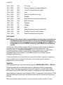
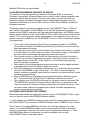
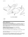
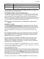
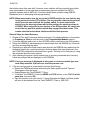
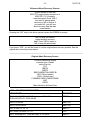
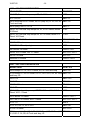
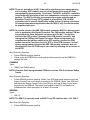
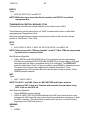
NUMBER:
GROUP:
DATE:
18-037-05
Vehicle Performance
October 20, 2005
This bulletin is supplied as technical information only and is not an authorization for repair. No part of this publication may be reproduced, stored in a retrieval system,
or transmitted, in any form or by any means, electronic, mechanical, photocopying, or otherwise, without written permission of DaimlerChrysler Corporation.
THIS BULLETIN SUPERSEDES SERVICE BULLETIN 18-020-02, DATED JUNE 24,
2002 WHICH SHOULD BE REMOVED FROM YOUR FILES. THIS IS A COMPLETE
REVISION AND NO ASTERISKS HAVE BEEN USED TO HIGHLIGHT REVISIONS.
SUBJECT:
Flash Programming Failure Recovery Using DRBIII®
OVERVIEW:
This Bulletin provides guidelines, to minimize flash reprogramming problems, and
information on recovery procedures for failed flash attempts.
MODELS:
1992 - 1994
(AA)
Spirit/Acclaim/Lebaron Sedan
1995 - 2003
(AB)
Ram Van/Wagon
1992 - 1994
(AJ)
Lebaron Coupe/Convertible
1995 - 2004
(AN)
Dakota
1992 - 1995
(AS)
Town & Country/Caravan/Voyager
1994 - 2002
(BR/BE)
Ram Pickup
2004 - 2006
(CS)
Pacifica
1998 - 2003
(DN)
Durango
2002 - 2005
(DR/DH/D1) Ram Pickup
1995 - 2000
(FJ)
Avenger/Sebring/Talon
1996 - 2000
(GS)
Chrysler Voyager (International Markets)
1995 - 2000
(JA)
Breeze/Cirrus/Stratus
2001 - 2006
(JR)
Sebring Sedan/Stratus Sedan/Sebring Convertible
1996 - 2000
(JX)
Sebring Convertible
2002 - 2005
(KJ)
Liberty/Cherokee (International Markets)
1993 - 2003
(LH)
Concorde/Intrepid/Vision/LHS/New Yorker/300M
1996 - 2000
(NS)
Town & Country/Caravan/Voyager
1995 - 2005
(PL)
Neon
2002
(PG)
PT Cruiser (International Markets)
1997 - 2002
(PR)
Prowler
18-037-05
-2-
2001 - 2005
(PT)
PT Cruiser
2001 - 2006
(RG)
Chrysler Voyager (International Markets)
2001 - 2006
(RS)
Town & Country/Caravan/Voyager
1995 - 2002
(SR)
Viper
2001 - 2005
(ST)
Sebring Coupe/Stratus Coupe
1997 - 2006
(TJ)
Wrangler
2001 - 2004
(WG)
Grand Cherokee (International Markets)
1999 - 2004
(WJ)
Grand Cherokee
1997 - 2001
(XJ)
Cherokee
1993 - 1995
(YJ)
Wrangler
2003 - 2006
(ZB)
Viper
1995 - 1998
(ZG)
Grand Cherokee (International Markets)
2004 - 2006
(ZH)
Crossfire Coupe/Crossfire Roadster
1993 - 1998
(ZJ)
Grand Cherokee/Grand Wagoneer
DISCUSSION:
NOTE: Many of the reasons a flash reprogramming procedure may not complete are
documented in this service bulletin, but if you are constantly having issues
performing the flash reprogramming procedure using a specific DRBIII®, it is
suggested you send the DRBIII® in question to SPX/Miller Special Tools for
service.
Occasionally a flash update procedure may not complete properly and/or the diagnostic
equipment may lock up or become disconnected during the procedure. Flash
Reprogramming is a "CRITICAL PROCESS"; an error may result in a no-start/failed
control module. Most modules, encountering an interruption or failure while
reprogramming, are recoverable; a recoverable module is not covered under the
provisions of the warranty.
This service bulletin covers items that may cause this condition, a process to restart the
flash procedure, and miscellaneous information that will help prevent needless
replacement of control modules.
GENERAL:
Flash Reprogramming is only authorized by a specific SERVICE BULLETIN, or RECALL.
Review the entire Service Bulletin/Recall prior to performing a flash reprogramming
update. Often other parts may need to be serviced, replaced, or tested, prior to flash
reprogramming, and ARE REQUIRED as part of completing the Service Bulletin/Recall.
When flashing a Powertrain Control Module (PCM) or Transmission Control Module (TCM)
there are other legal requirements with labeling issues that are included in those service
bulletins.
Other non-emission related modules, such as instrument clusters and Body Control
-3-
18-037-05
Modules (BCMs) do not require labels.
FLASH REPROGRAMMING SEQUENCE OF EVENTS
The process of flash reprogramming is similar to flashing the BIOS on a Personal
Computer. Interruptions, voltage problems, and a variety of other outside interactions can
potentially interfere with the process. This document seeks to provide information to
minimize problems associated with vehicle control module flash reprogramming. The
description that follows is for most PCMs and some TCMs. Other modules use different
initiation procedures.
The process starts by selecting an update from the TechCONNECT Client or ISIS and
then "loading" that update into the DRBIII®. Once the flash reprogramming update is
loaded into the DRBIII®, and before the flash reprogramming begins, the DRBIII® verifies
that the update loaded from the TechCONNECT Client or ISIS is the proper update for the
module. This is done using part number supersedence. This verification occurs only if an
update is required, available (on the TechCONNECT Client or ISIS) and has been selected
for programming.
•
•
•
•
•
•
•
The module is then placed into "Boot Strap" programming mode by the DRBIII®.
This module mode gives the DRBIII® permission and the ability to proceed with the
flash reprogramming session.
Next, the current part number, which resides in the module's flash memory, is stored
in a "Safe Memory" location within the module. This memory location is not affected
by flash memory erasure and reprogramming, which are to follow.
Once the part number is safely stored, the flash memory in the control module is
erased. From this point forward any interruption in the flash process, will result in a
Non-Responsive module (NR). A NR module is a module that is either partially
erased or partially programmed.
After erasure, the actual reprogramming procedure starts, and the update software
is programmed into the flash memory within the module.
When reprogramming is completed, the flash memory is verified through an internal
process in the DRBIII® using a "Check Sum". This value is compared against
another value that represents what should be in memory and when matched, verifies
successful reprogramming.
Next, a DRBIII® prompt is displayed instructing that the ignition switch be turned
OFF. The module exits the "Boot Strap" mode when the switch is turned off.
After a slight pause, the DRBIII® will prompt for the ignition switch to be turned ON.
The DRBIII® then reads the new part number in flash memory (along with a new
computer program the new part number is placed into the module's memory). If the
new part number matches the expected part number, the flash reprogramming
session has completed successfully.
SOFTWARE VERSIONS MUST BE CURRENT
Before attempting a flash reprogramming session using the TechCONNECT Client, make
sure you have the most current DRBIII® software installed.
To verify whether your DRBIII® software is current, check the upper right-hand corner of
the TechCONNECT Client screen for DRBIII® Available Version, DRBIII® Current Version.
Often, because of multiple DRBIII®s in the shop, not all will get updated on a timely
manner. The installed DRBIII® software version can generally be found at the bottom
center of most screens. Alternately the version can be checked by pressing 6, 2, 5 from
the DRBIII® Main Menu and comparing it to what is available from a current
TechCONNECT Client as described above.
18-037-05
-4-
If the TechCONNECT Client is current and the DRBIII® is not, it may be due to the fact
that the TechCONNECT Client does not force DRBIII® updates for "minor" revisions.
Changes and new support are added to the Vehicle Flash application on "minor" revisions
on a regular basis. This is why your TechCONNECT Client and DRBIII® must have the
LATEST software revisions installed.
DO NOT PASS on the option for updating to a "minor" revision!
Major updates require the DRBIII® to be updated prior to allowing any flash programming.
DRBIII® CABLES
A NEW DRBIII® cable was released as an Essential Service Tool! CH7000A - 8 ft.
Cable, DRBIII® to OBDII (J1962) DLC Connector.
CH7000A is the required cable for ALL flash reprogramming. The older CH7000 cable can
be used for diagnostics ONLY. One (1) cable was shipped to all dealerships.
Easily identified, the correct cable has a RED connector, which plugs into the DRBIII®.
The cable modification enhances the DRBIII® communication capabilities when dealing
with the flash requirements of certain controllers/ECUs affected in part by the recent
changes in DLC connector configurations.
The new cable is required for ALL flash reprogramming sessions, and can be used
wherever the previous CH7000/7001 cables were used. To place additional cable orders
for all your DRBIII®s, call 1-800-223-5623.
Fig. 1 CH7000A CABLE
1 - DRBIII® CONNECTOR (RED)
While not recommended for flash reprogramming usage, if you require a longer cable,
there is also a 12-foot cable released under p/n CH7001A
The production of the previous CH7000/7001 cables has ceased. All orders placed will be
superseded to part number CH7000A/CH7001A.
-5-
18-037-05
NOTE: Consider all cables wear items. Always inspect for worn, damaged cables,
connectors that are damaged or do not lock securely, and all mating
connections including checking for corrosion on the pins. REPLACE ALL
suspect cables. Do not use worn or damaged cables when flash
reprogramming.
Failure to use the new cable or to use a damaged cable often results in failed flash
reprogramming sessions.
The 2 door Sebring, Stratus, and Avenger coupes (supplied by MMC) generally use the
CH7010 cable (Pre-OBDII MMC vehicles will use the CH7005 cable).
TechCONNECT CABLE (GPIB)
Replace any suspect GPIB cable.
The GPIB cable provides the connection between TechCONNECT Client and the DRBIII®.
This cable is used by the TechCONNECT Client for vehicle part number reads and to send
update files to the DRBIII®.
Inspect this cable for loose connections, damaged connectors or terminals, and wear and
tear. If this cable becomes disconnected during a flash session, you may have to reload
the update file that you selected on the TechCONNECT Client.
TROUBLESHOOTING CONNECTIVITY OF THE DRBIII® UNIT TO THE TechCONNECT
APPLICATION.
1. Turn-on the power to the DRBIII® unit.
2. Select option 2 “Connect to TechCONNECT” and press Enter.
3. Attach the male mini D-shell amphenol GPIB connector of the new DRBIII® cable
(part number CH7035B) to the DRBIII® unit.
4. Insure that the larger female D-shell amphenol GPIB connector of the new DRBIII®
cable is properly attached to the male D-shell amphenol GPIB connector on the
GPIB-USB-B protocol converter, (part number CHGPIB-B).
5. Attach the USB cable from the GPIB-USB-B protocol converter to one of the USB
ports on the rear panel of the client CPU.
6. When the cable is attached to the USB port of the CPU for the first time, Windows
2000 will detect the device and install software for it. Please wait for 25-30 seconds to
complete the installation.
18-037-05
-6-
Fig. 2 CH2002 ASSEMBLY
1 - CH7035B
2 - CHGPIB-B
3 - CH7036
ISIS NULL MODEM CABLE
Replace any suspect null modem cables.
International (ISIS), a PC-based CD program similar to TechCONNECT Client uses a null
modem cable for vehicle part number reads and to send update files to the DRBIII®.
Inspect this cable for loose connections, damaged connectors or terminals, and wear and
tear. If this cable becomes disconnected during a flash download session, you will have to
reload the update file or files.
GENERAL NOTES FOR CABLES AND VEHICLE CONNECTIONS
Consider ALL cables to be wear items.
Many successful dealers have dedicated cables devoted to "Flash ONLY".
Always have spare CH7000A, CH7010 and CH2002 GPIB or null modem cables available.
Inspect vehicle diagnostic connectors for potential problems that might cause
communication interruptions.
There are now clip repair kits available through teamPSE to replace the retaining clips for
two of these cables. To protect the DRBIII® from internal damage, the clips are designed
to fail at above 25 lbs. of axial force. Kits are described in the following table.
-7-
18-037-05
teamPSE Part No.
Description
OT-CH7000A-1
J1962 Banjo Clip Repair Kit.
OT-CH7035B-1
GPIB Cable Cup Kit.
The kit contains - 4 retaining clips, 2 pivot pins, and instructions.
It is a good practice to discard cables that have damage to the pins, cuts, corrosion, or
general damage beyond the retaining clips.
ST22 SEBRING STRATUS 2 DOOR COUPES (2001-2005)
These vehicles use MMC based modules. The CH8432 Supplemental Reprogramming
Tool (SRT) was shipped as a 2001 Essential Tool. The flash reprogramming update files
will be downloaded from TechCONNECT Client to the SRT for flash reprogramming
sessions on these vehicles. Users should closely follow the instructions that come with the
tool. If the tool has not been initialized, there is a known condition where it may take up to
5 or more attempts for it to fully initialize and become functional.
NOTE: Once it has successfully flashed, it is initialized and no further action is
required.
PREPARING TO FLASH
It is highly recommended that a sign, or other process, be used that notifies other users
that a FLASH SESSION IS IN-PROGRESS and must NOT be interrupted. Interrupting
some flash reprogramming sessions at critical junctures can render a module inoperative.
Another user may not realize that a flash session is in-progress and may disturb or
disconnect the DRBIII® or do something on the vehicle that could interrupt the flash
process.
Before starting the flash session, read, record and erase all DTCs found on the vehicle.
Also "Cold Boot" the DRBIII® and download the flash since this will erase the flash file
from the DRBIII® memory. (To "Cold Boot", press the MORE and YES buttons on the
DRBIII®, at the same time. Then press "F4").
Be sure to arrange the TechCONNECT and DRBIII® so that no cables are stretched
across an area where someone might trip over or kick a cable. When setting up your
DRBIII®, insure that it rests on a surface where it will not fall or be bumped during
reprogramming e.g.: DRBIII®s have been known to be swept off vehicle windshields by
accident when a user bumps the wiper switch).
Check User settings on the DRBIII®. From the DRBIII® Main menu, press 6, 1 and check
to make sure item 1. Echo on PC is set to OFF. On occasion, when Echo on PC is set to
ON, flash reprogramming errors may occur.
VEHICLE BATTERY VOLTAGE
The flash programming procedure puts a load on the electrical system that may last from
five to twenty minutes depending on the particular flash reprogramming update. Connect a
battery charger to the vehicle. Set the charger to as close to 14 volts as possible. If the
charger has a timer, set it for 30 minutes BEFORE starting a flash reprogramming session.
This will help to prevent unwanted resets by either the DRBIII® and/or the vehicle module
that are caused by voltage fluctuations.
Alternately, as a bare minimum, use a "Battery Jump Box" when a battery charger is
18-037-05
-8-
unavailable to ensure adequate and stable system voltages on the module being flash
reprogrammed.
CONNECTED MODE FLASHING USING TechCONNECT
NOTE: Capable but not recommended.
In this mode, the DRBIII® remains connected to the TechCONNECT Client and the vehicle
throughout the flash session. The DRBIII® is connected to the TechCONNECT Client
using the GPIB (CH7035) cable and to the vehicle using the vehicle I/O cable (the
CH7000A for most vehicles).
This mode is useful when the TechCONNECT Client is next to the vehicle being flashed.
Another advantage of this mode is that you are able to determine all available flash
updates for the vehicle you are connected to by clicking on the "Read Part Number(s)
From Vehicle" button.
Again, it is important that other users do not attempt to reboot or move the TechCONNECT
Client while a flash update is in-progress.
The reprogramming procedure of this mode is initiated by selecting the controller option
and clicking “Download/Update” button on the TechCONNECT client.
DISCONNECTED FLASH MODE
NOTE: This is the preferred method.
This mode allows a user to flash a vehicle without being connected to the TechCONNECT
Client. This is a popular mode for flashing in a remote area of the service garage or in a
back lot.
Before you attempt to use this mode, you must configure the DRBIII® for the desired
update(s). To do this, you must connect the DRBIII® to the TechCONNECT Client using
the GPIB cable and the CH7025 cable. It is not necessary to be connected to a vehicle.
The GPIB (CH7035) cable will be used to communicate with the TechCONNECT Client
(for update file downloading) while the CH7025 cable is used to provide power to the
DRBIII®.
After making the above connections, you are able to select one or more updates that you
want to perform. These selections are made by highlighting the desired updates and then
clicking on the "Download/Update" button by selecting the DRBIII® option on the
TechCONNECT client. Obviously, the DRBIII® does not have unlimited memory. If the file
size of the selected updates exceeds 948 KB, the "DRB Space Used" indicator (at the
bottom-center of the TechCONNECT Client screen) will change color from GREEN to
RED. At this point you must de-select entries until the indicator changes color to GREEN
again.
When the updates have finished downloading, you may disconnect from the
TechCONNECT Client and take the DRBIII® to wherever the vehicle is located. The
updates will remain in DRBIII® memory for 8 hours while the DRBIII® is without power. If
the DRBIII® is powered up for several minutes before the 8 hour time period has expired,
the update files will remain on the DRBIII® for another 8 hours without power.
-9-
18-037-05
To start the actual flash process, after connecting to the vehicle in Disconnected Mode,
you must press "7 - Vehicle Flash" from the Main Menu on the DRBIII®. Step by step
instruction will follow on the DRBIII® display. As with Connected Flash Mode, take the
necessary precautions to insure that others are aware of the flash session and that nothing
disturbs the vehicle, DRBIII®, or cabling while performing the flash. Remember to use a
battery charger set to 14 volts or a "battery jump box".
PAY ATTENTION WHILE PERFORMING FLASH REPROGRAMMING PROCEDURES
Before downloading the flash files, double check to see if the files that you have selected
are the appropriate ones for that vehicle. Don't forget about the "Read Part Numbers
From Vehicle" option on TechCONNECT Client, this can be of great assistance when
trying to flash a module. If the files selected don't download on the first attempt, try again.
The technician should NOT leave the vehicle when flash reprogramming a module.
Again, check to make sure that all cable connections are secure and that the DRBIII®
rests on a stable surface. If you are using a battery charger, insure that the settings and
charging times are correct and that the battery post clamps are securely fastened.
Read, record, and erase all DTCs found on the vehicle. Read and record the module type
and part number from the module that is to be flash reprogrammed.
Some control modules are not “abort-recovery” capable. When this is true, the scan tool
will indicate so by displaying a WARNING message prior to the start of reprogramming.
For these modules it is especially important that all precautions and procedures, outlined
here, are carefully followed.
Pay special attention to DRBIII® screen directions relating to key cycles. Missing a "Key
ON" or "Key OFF" can cause the module to have to be reflashed again. Due to the variety
of module types and vehicle options, you can't always anticipate key prompts, so be alert
and ready to respond to DRBIII® instructions.
Some screens will also instruct that certain modules, connectors or fuses be disconnected
or pulled prior to the start of reprogramming and re-installed immediately after completion.
Be careful not to anticipate the steps or order of operations for reprogramming any vehicle
modules. Because of the many possible changes that occur with each new release of scan
tool software, always allow the TSB/Recall and scan tool instructions to be your guide
while performing flash reprogramming.
Flash reprogramming sessions usually range from 5 to 20 minutes. If the flash session has
not completed within 25 minutes after starting a flash reprogramming update, an error has
most likely occurred (Record the message that appears on the screen when a failure
occurs). If this is the case, or if you know that the flash process was interrupted, cycle the
ignition key (OFF to the locked position, then back ON). Reset the DRBIII® (power down
for 4 seconds and then power up) before attempting to restart the flash process. If the
module still won’t respond, turn the ignition key off, disconnect the module from the vehicle
for 2 minutes, reconnect the module, turn the ignition key to run and try to restart the flash
process again.
Regardless of what mode that you are in (Connected Flash or Disconnected Flash), if you
have tried twice (2 times) unsuccessfully to do a flash recovery and ALL DRBIII®
18-037-05
-10-
instructions were followed, perform the following:
•
•
•
•
Cold boot the DRBIII®. This resets memory and removes all update files from the
DRBIII®. (Push MORE and YES buttons at the same time, then press F4).
Reload the flash update file from the TechCONNECT Client.
If it fails to complete in the connected mode, first reboot the TechCONNECT Client
before re-attempting the flash download to the DRBIII®.
Proceed to reflash the module.
On vehicles that have multiple flash updates available, always complete and verify each
flash update before attempting the next one.
After all flash reprogramming is completed, read and erase all DTCs in all modules on the
vehicle. A variety of DTCs may be set, which are usually related to a loss of
communication with the module(s) being reprogrammed.
Verify the update by reading the new part number using the DRBIII®. A good double check
is to read the part number using DRBIII® stand alone.
At times, other modules, wired in parallel, to the DLC connector have prevented flash
reprogramming sessions to be successful. After the failed attempt, review the appropriate
wiring diagram for the vehicle you are flash reprogramming and, with the key “OFF”;
disconnect the other modules and retry the flash. Complete the flash, turn the key “OFF”
and reconnect any modules that were disconnected. Refer to the “Programmable Modules”
section later in this document for more information.
ERROR MESSAGES
Block Echo/Compare Errors
Block Echo and Block Compare errors are often caused by voltage fluctuations, faulty I/O
cables (CH7000A, CH7005, CH7010) or faulty communication connections at the
diagnostic connector. Inspect for these conditions and review the sections on Vehicle
Battery Voltage and Cable recommendations.
Checksum Errors
Checksum Errors are generally caused by corrupt flash update files, which can be caused
by DRBIII® memory problems. If the DRBIII® has been without power for more than 8
hours, the update files and system memory could be in a corrupted state. "Cold Boot" the
DRBIII®. (To "Cold Boot", press the MORE and YES buttons on the DRBIII®, at the same
time. Then press “F4”). Reload the flash update file(s) from the TechCONNECT CLIENT.
If it fails to complete in the connected mode, first reboot the TechCONNECT Client before
re-attempting the flash download to the DRBIII®. Then re-attempt the flash reprogramming
process.
ENHANCED ABORT RECOVERY
Interruptions in the flash process are one of the main reasons for failed flash sessions and
non-responsive (NR) modules. Interrupting the flash process after the erase phase has
started will leave the control module in a non-functional state.
Generally, but not always, NR modules may be recovered successfully.
Briefly, abort recovery is the process used to get a NR module back to a fully functional
state with the latest software update. The technician should be familiar with the other
sections in this document and follow all DRBIII® user prompts carefully.
-11-
18-037-05
There are two methods for abort-recovery. The newer method is called “Enhanced Abort
Recovery”. This is the preferred method since the original method takes several minutes
longer and requires the correct selection of module type from a list of possible PCM’s or
TCM’s.
Starting with Release 60.1, a new useful feature was added to the flash reprogramming
application for Engine and Transmission control modules. The DRBIII® “writes” the YME
and Controller Type information to a “Safe Memory” location . This method allows for rapid
recovery of the module part number and minimizes errors that could otherwise be made by
selecting the wrong controller type. It also assumes that the user will attempt abort
recovery for a failed flash attempt before moving to another vehicle with the same
DRBIII®. If you need to move to another vehicle for flash reprogramming you must erase
the saved recovery information in order to successfully perform flash reprogramming. Be
careful to match the YME information displayed on the enhanced abort recovery screen
with the vehicle and module that you are attempting to recover. If you use the recovery file
on a different vehicle and module you could damage the module.
The recovery information will be displayed on your DRBIII®, at the start of a flash session,
only if you previously encountered a problem that prevented a flash session from
completing normally. If your prior flash session was successful, the DRBIII® automatically
erases the recovery file so that the flash application will not show any recovery information
at the start of your next flash session.
Enhanced abort recovery features:
•
•
•
•
•
•
•
Reduces the amount of time for the Module ID process.
Lowers the risk of possible user mistakes by presenting the user the Year, Model,
Engine, and Controller Type.
Currently only applicable to Engine and Transmission flash reprogramming.
The enhanced abort recovery file will only be erased upon a successful flash or
manually by the user.
Cold booting (simultaneously pushing MORE & YES, then F4) the DRBIII® will not
erase the enhanced abort recovery file, but cold booting the DRBIII® will still erase
the flash file so it can be reloaded.
The user has a choice, at the start of a flash session , whether or not to use the
enhanced abort recovery feature. If the user chooses to erase the recovery file, then
the DRBIII® will use the original method of abort recovery.
Cycling the ignition key, when prompted by the DRBIII®, is still necessary to put the
controller into bootstrap (reprogramming) mode.
ORIGINAL ABORT RECOVERY
If the choice is made to use the original method of abort recovery, a NR module is not
always able to provide the DRBIII with ID information. In this case the technician must
enter this when prompted by the DRBIII®. Be patient when performing this process. If the
module does not respond to standard diagnostic requests, the DRBIII® may take several
minutes before it determines that the engine module is in a NR state. At this point, the
DRBIII® displays the prompt "Could not determine engine controller type. Please select
from list" along with a list of possible controller types (if the DRBIII® is attempting to
identify a TCM, the prompt will say "trans" instead of "engine" and list the possible trans
controller types). Because of module variations, it is important to correctly identify the
PCM/TCM type so that the correct flash procedure is used. Failure to do this will cause
further problems and may damage the module. Tables are provided below to help identify
the proper module type to select. These tables correctly identify the modules that were on
18-037-05
-12-
the vehicles when they were built. However, some vehicles will have module types which
were superseded to a new type when a replacement part was installed (ie: EATX4
modules replaced with an EATX4A). Correctly identify these modules using DRBIII®
Standalone prior to attempting flash reprogramming.
NOTE: When instructed to turn the key to the LOCKED position, be sure that the key
is not just turned to the OFF position. The key must be rotated to the point at
which it can be removed from the ignition switch. On most vehicles the
switch is on the steering column and at this position the steering column is
LOCKED. When instructed to turn the key to the RUN position, be careful not
to turn the key past this position which may engage the starter motor. This
creates electrical noise which interferes with the flash process.
General Steps for Abort Recovery
1. Review all Tips and Techniques before continuing. Pay special attention to the section
on Preparing to Flash a controller and to the Programmable Modules section.
2. Cycle the vehicle's ignition key to the LOCKED position and back to the RUN position.
3. Reset the DRBIII® by disconnecting the vehicle cable from the DRBIII® for 4 seconds
and then reconnecting the cable.
4. Depending on where the flash session was aborted, the DRBIII® may require that the
technician identify the control module type that was being flash reprogrammed. Use
the PCM/TCM configuration table below as a guide. This step is not necessary if using
the enhanced abort recovery method.
5. After selecting the proper control module type or choosing enhanced abort recovery,
follow the prompts that are displayed on the DRBIII®.
NOTE: If an error message is displayed at this point, an incorrect module type was
most likely selected. If this occurs, start the process over.
6. If the recovery process is unsuccessful, perform the following:
a. Review the TSB/Recall notice (authorizing the flash update) and all Tips and
Techniques in this document.
b. Reboot/Restart the TechCONNECT Client.
c. "Cold Boot" the DRBIII®. (Press the MORE and YES buttons on the DRBIII® at the
same time, then press F4).
d. Start this process over from item #1. If using Disconnected Mode, the flash update
will have to be reloaded from the TechCONNECT Client or ISIS DVD.
-13-
18-037-05
Enhanced Abort Recovery Screens
A prior attempt to flash the
NGC ETC engine control module on a
2003 DR 5.7L V8 vehicle,
was interrupted. Press YES if
you want to attempt abort
recovery or NO to decline. If
you press NO, you will lose
abort recovery data that was
saved earlier!
Pressing the “NO” key for the above screen causes the DRBIII® to prompt:
Are you sure you want to
erase the abort-recovery
data? Press YES to erase or
NO to keep the saved data
If you press “YES”, you will be forced to use the original abort recovery method. See the
original abort recovery screen below.
___________________________________________________________________________
Original Abort Recovery Screen
Could not determine engine
controller type. Please
select from list.
FCC
SBEC2
SBEC3
SBEC3A/SBEC3A+/SBEC3B
JTEC (98 and earlier)
JTEC+ (99 and later)
CUMMINS CM551/CM845/CM848
NGC
SIM70
Make Selection & Press Enter
1992 - 1999 PCM CONFIGURATION
YEAR/ MODEL
PCM TYPE
92-95 All, 96-97 ZG, XJ 2.5 Diesel except 94 LH, 95
FJ/JA/J2/LH/PL/P1, 93-95 AA/AS
SBEC 2
94 LH, 93 AA/AS
SBEC 2A
95 LH, 94-95 AA/AS
SBEC 2B
95 FJ/F24S 2.5, JA, J2
SBEC 3
95 FJ/24S 2.0 DOHC, PL, P1
FCC
96-97 All except SR, Truck and Jeep, 97 FJ/JA/JX
SBEC 3
18-037-05
-14-
1992 - 1999 PCM CONFIGURATION
YEAR/ MODEL
PCM TYPE
96-97 SR, Truck and Jeep except ZG, XJ 2.5 Diesel
JTEC
97 FJ, JA, JX
SBEC 3+
98-99 All except GS 2.5 Diesel, NS 3.0 (early 99), PL 2.0, SR, All
Truck and Jeep
SBEC 3A
98-99 (early) NS 3.0, PL 2.0
SBEC 3
98 SR, All Truck and Jeep except AN, XJ, ZG 2.5 Diesel, BR/BE
5.9 Diesel
JTEC
99 SR, All Truck and Jeep except AN, XJ 2.5 Diesel, BR/BE 5.9
Diesel, WG Diesel
JTEC+
98 AN, XJ, ZG 2.5 Diesel
SBEC 2B/ MSA-15
98 GS 2.5 Diesel
MSA-15
98 BR/BE 5.9 Diesel (early)
JTEC
98½ BR/BE 5.9 Diesel
CM551/ JTEC
99 AN, XJ 2.5 Diesel, WG 3.1 Diesel
EDC15-V/ JTEC+
99 GS 2.5 Diesel
EDC15-V
99 BR/BE 5.9 Diesel
CM551/ JTEC+
2000 - 2002 PCM CONFIGURATION
MODEL/YEAR
PCM TYPE
00 All except LH, PR, GS 2.5 Diesel, SR, All Truck and Jeep
SBEC 3A
01 All except PL, RG 2.5 Diesel, RG 3.3, RS 3.3/3.8, SR, All Truck SBEC 3A
and Jeep, JR
00 LH, PR
SBEC 3A+
01-02 JR
SBEC 3A+
00 GS 2.5 Diesel
EDC15-V
00-02 SR
JTEC+
00-01 All Truck and Jeep except BR/BE 5.9 Diesel, AN, XJ 2.5
Diesel, WG 3.1 Diesel
JTEC +
00-02 BR/BE 5.9 Diesel
CM551/ JTEC +
00-01 AN, XJ 2.5 Diesel, WG 3.1 Diesel
EDC15-V/ JTEC +
01 PL 1.6
SIM70
01 PL 2.0, RG 3.3, RS 3.3/3.8
SBEC 3B
01 RG 2.5 Diesel
EDC15-C5
02 All except LH, PL 1.6/2.0, PG 1.6/2.2 Diesel, RG 2.5 Diesel, RG SBEC 3A
3.3, RS 3.3, 3.8, SR, All Truck and Jeep, JR
-15-
18-037-05
2000 - 2002 PCM CONFIGURATION
MODEL/YEAR
PCM TYPE
02 All Truck and Jeep except BR/BE 5.9 Diesel, DN 4.7 (Early 02), JTEC +
KJ 2.5 Diesel, WG 2.7 Diesel
02 LH
NGC
02 PG/PL 1.6
SIM70
02 PG 2.2 Diesel, RG 2.5 Diesel, KJ 2.5 Diesel, WG 2.7 Diesel
EDC15-C5
02 PL 2.0, RG 3.3, RS 3.3, 3.8
SBEC 3B
02 DN 4.7 (Late 02)
NGC
2003 PCM CONFIGURATION
YEAR/MODEL
PCM TYPE
03 All except JR 2.7, PT 1.6, 2.2 Diesel, PL 1.6, RG 2.5 Diesel, RS NGC
3.3, 3.8, ZB, All Truck and Jeep except AN/DN/DR 4.7 (early)
03 JR 2.7
SBEC 3A
03 PG/PL 1.6
SIM70
03 PT 2.2 Diesel, RG 2.5 Diesel, KJ 2.5/2.8 Diesel, WG 2.7 Diesel EDC15-C5
03 RG 3.3, RS 3.3, 3.8
SBEC 3B
03 ZB, All Truck and Jeep except AN/DN/DR 4.7 (late), DR 5.9
Diesel, DR 5.7, KJ 2.5 Diesel, WG 2.7 Diesel
JTEC +
03 DR 5.9 Diesel
CM845/ JTEC +
03 DR 5.7L
NGC2
2004 PCM CONFIGURATION
YEAR/MODEL
PCM TYPE
AN, late CS, DR, KJ, JR (2.0L, 2.4L, and late 2.7L), PL, PT, RG,
RS
NGC3
JR 2.7 (Early)
SBEC 3A
CS (Early)
NGC1
PL/PT (BUX) 1.6
SIM70
PT 2.2 Diesel, RG 2.5 Diesel, KJ 2.5/2.8 Diesel, WG 2.7 Diesel
EDC15-C5
ZB, WJ, TJ, and SRT - 10
JTEC +
DR 5.9 Diesel
Cummins CM848
ZH
ME 2.8 Bosch
ST-22
MMC - Melco
18-037-05
-162005 PCM CONFIGURATION
YEAR/MODEL
PCM TYPE
CS, DR, JR, KJ, PL, PT, RG, RS, TJ
NGC3
PT (BUX) 1.6
SIM70
PT 2.2 Diesel, RG 2.5/2.8 Diesel
EDC15-C5
KJ 2.8 Diesel
EDC16
ZB and SRT - 10
JTEC +
DH 5.9 Diesel
Cummins CM848
ZH
ME 2.8 Bosch
ST-22
MMC - Melco
2006 PCM CONFIGURATION
YEAR/MODEL
PCM TYPE
DR, JR, KJ, PL, PT, RG, RS, TJ
NGC3
CS
NGC3A
PT (BUX) 1.6L
SIM70
KJ 2.8 Diesel, PT 2.2 Diesel, RG 2.5/2.8 Diesel
EDC15-C5
ZB and SRT - 10
JTEC +
DH 5.9 Diesel
Cummins CM848
ZH
ME 2.8 Bosch
ST-22
MMC - Melco
The TCM Configuration Tables apply to vehicles that use an EATX/NGC/AW4 controller.
Applications using the PCM module (JTEC/SBEC) for assisting transmission shifting or
TCC operation are not listed since the transmissions are not fully electronic.
1992 - 2000 TCM CONFIGURATION
YEAR/MODEL
TCM TYPE
92 All FWD except BB
EATX*
93-95 All FWD (only LH is flash capable)
EATX 2**
96-97 All FWD
EATX 3
98-00 All FWD except PL
EATX 3A
92-00 XJ 4.0
AW4
99-00 AN, DN, WJ/WG 4.7
EATX 4***
* EATX controllers (89-92) are NOT flash programmable, all supersede to EATX 2.
** EATX 2 controllers need CH5500 for flash reprogramming.
-17-
18-037-05
*** The EATX 4 uses an EATX 4A for service replacements.
2001 - 2003 TCM CONFIGURATION
YEAR/MODEL
TCM TYPE
01 All FWD
EATX 3B
02 All FWD except LH
EATX 3B
03 All except RS 3.3/3.8, JR 2.7, DR 5.7 (NGC w/ETC), TJ, KJ,
WJ/WG 4.7/WG 2.7 Diesel
NGC
01 PT (early)
EATX 3A
01 XJ
AW4
01-02 AN/DN, WJ/WG 4.7, DN (early)
EATX 4
02 LH, DN (late)
NGC
02-03 WG 2.7 Diesel
EGS52
03 RS 3.3/3.8, RG 3.3, JR 2.7, TJ, KJ (late), RG 3.3
EATX 3B
03 DR 5.7 (NGC wETC), KJ (early), KJ 2.8 Diesel, WJ/WG 4.7
EATX 4
2005 TCM CONFIGURATION
YEAR/MODEL
TCM TYPE
CS, DR 3.7, 4.7, & 5.7, DH/D1 5.7, JR, HB, KJ 3.7, LX/LE 2.7 &
3.5, ND, PL, PT 2.4, RS/RG 2.4, 3.3 & 3.8, TJ WK, WH 4.7 & 5.7
NGC3
RG 2.8 Turbo Diesel,
EATX 3B
DR 8.3, ZB
JTEC
DH/D1 5.9 HO TD
CM848
PT Turbo Diesel
EDC15C5
2006 TCM CONFIGURATION
YEAR/MODEL
TCM TYPE
CS, DR 3.7, 4.7, & 5.7, JR, KJ 3.7, LX/LE 2.7 & 3.5 (w/ 42RLE), PT NGC3
2.4, ND, RS/RG 2.4, 3.3 & 3.8, TJ 2.4 & 4.0, WK, WH 3.7 & 4.7,
XK, XH 4.7 & 5.7
RG 2.8 Turbo Diesel,
EATX 3B
DR 8.3, ZB
JTEC
DH 5.9 HO TD
CM848
PT Turbo Diesel
EDC16C2
PROGRAMMABLE MODULES
The following pages list the various modules that have flash reprogramming capability. It
does not mean that a flash is currently available. What will be described are the module
18-037-05
-18-
types and variations, followed by items to note, and finally, abort recovery specifics if
applicable.
POWERTRAIN MODULES - ENGINE AND TRANSMISSION
ENGINE - POWERTRAIN CONTROL MODULE (PCM)
There are a variety of Engine (PCM) modules that are flash reprogrammable. Suggestions
that are somewhat unique to each type will have comments. Prior to reprogramming a
PCM, retrieve the module information and module type using your DRBIII®. PCM
information is used by many modules. Be sure to check DTC's before and after
performing all flash reprogramming event.
The DTC's associated with flash reprogramming generally relate to "lack of
communication" with the other modules during the reprogramming session.
SBEC
Types:
•
SBEC, SBEC 2, SBEC 3, SBEC 3+, SBEC 3A, SBEC 3A+, and SBEC 3B
NOTE: During recovery, if the DRBIII® is not seeing the key off, you may need to
remove power (B+) to PCM by removing fuse(s) or disconnecting the PCM.
When DRBIII® states to turn key ON, reconnect fuse or harness connection.
Abort Recovery Specifics:
•
•
Follow instructions on the DRBIII® for the module type. See table above.
Some SBEC 3A, SBEC 3A+ AND SBEC 3B may be in a state where they can not
correctly identify a key cycle. In this case a Modified Key Cycle routine is required.
This state is present when the following message is displayed on the DRBIII®: "Can not
read Part Number. Did not see Key On or PCM/TCM Controller may not be
flashable". When this occurs restart the flash session and when prompted to turn the
ignition key to the LOCKED position, pull the fuse(s) that supply battery power to the
module instead. When prompted to turn the key to the RUN position, replace the battery
supply fuse(s) instead.
JTEC
Types:
•
JTEC, JTEC +
NOTE: Viper ALL - Roll down windows especially Coupes before attempting a flash.
NOTE: 1999 WJ JTEC with Speed Proportional Steering module. Disconnect before
and reconnect after the PCM flash reprogramming session. Also see
Transmission.
Abort Recovery Specifics:
•
Follow DRBIII® prompts carefully.
NGC
Types:
•
NGC 1, NGC 2, and NGC 3
-19-
18-037-05
NOTE: There are derivatives of NGC 3 that will be significant when reprogramming
and or testing. NGC modules use one of the longest time spans for flash
reprogramming (approximately 15 minutes). The NGC1 and NGC3 controllers
incorporate both an engine as well as a transmission controller in a common
package. The NGC2 controller incorporates the engine controller and an
Electronic Throttle Control (ETC) module in place of the TCM. All NGC
controllers can be visually identified by noting its four (4) wiring connectors.
On manual transmission applications and the NGC2, only 3 connectors may
be populated with pins.
NOTE: On certain vehicles, the ABS CAB module connector MUST be disconnected
prior to performing this Repair Procedure. The CAB module and the PCM are
connected at the same diagnostic connector pin (Pin #9). Turn ignition
switch to the OFF position, disconnect the CAB module connector, and
reprogram the PCM per the Repair Procedure. When reprogramming is
complete turn the ignition switch to the OFF position, connect the CAB
module connector, and then check for DTC's. If the PCM becomes “locked”
during reprogramming because the ABS CAB module connector was not
disconnected, then the PCM may be recovered by following the procedure in
this NOTE.
Abort Recovery Specifics:
•
•
Follow DRBIII® prompts carefully.
Power down the DRBIII® then cycle ignition before powering up the DRBIII® to
attempt the flash.
CUMMINS
Types:
•
CM551 and CM84x series
NOTE: Cummins flash reprogrammable PCMs are used on 1998.5 and newer Dodge
Trucks.
Abort Recovery Specifics:
•
Follow DRBIII® prompts carefully. Model Year 2000 and earlier vehicles have one
Engine Control Fuse to pull when prompted by the DRBIII®. Model Year 2001 and
later have two Engine Control Fuses (one 20 Amp and one 30 Amp) to pull when
prompted by the DRBIII®. The fuse(s) are located in the PDC and need to be
pulled/removed, when prompted, for at least 10 seconds.
SIEMENS
Types:
•
SIM-70
NOTE: The SIM-70 is currently used on BUX PL and PG vehicles with a 1.6L ONLY.
Abort Recovery Specifics:
•
Follow DRBIII® prompts carefully.
18-037-05
-20-
BOSCH
Types:
•
EDC15V, EDC15-C5, and EDC16
NOTE: While there have been other Bosch modules, the EDC15V is not flash
reprogrammable.
TRANSMISSION CONTROL MODULES (TCM)
Transmission controllers are usually flashed on the vehicle (since 1996).
Technicians may set the pinion factor on "NEW" modules either before or after flash
reprogramming. Suggestions follow.
After flash reprogramming and before returning the vehicle to the customer, always
perform a “QuickLearn” to the TCM.
EATX
Types:
•
EATX, EATX 2, EATX 3, EATX 3A, EATX 3B, EATX 4, and EATX 4A
NOTE: Table shows which TCM was installed "as-built". Often TCMs are superseded
by parts and or a service bulletin.
Abort Recovery Specifics:
•
1999 - 2000 WJ and 2000 AN/DN using 4.7L engines the service replacement
EATX4A part numbers 56041814AD and 56028227AH currently display a P/N read
failed error after the flash is completed during P/N verification. This DOES NOT
mean the flash failed. Check for the part number using DRBIII® in standalone mode.
This exists only for the service replacement modules listed above. Flash
reprogramming for OE modules flash and read the part number correctly. Follow
DRBIII® prompts carefully.
NGC
Types:
•
NGC 1, NGC2, NGC 3
NOTE: The NGC 1 and NGC 3 have the EATX/XCORE and Engine modules
combined. NGC 2 does not. Vehicles with automatic transmissions using
NGC 2 will use an EATX 4A.
Abort Recovery Specifics:
•
•
Follow DRBIII® prompts carefully.
2002 DR, 2002.5 DN, 2003 AN/DN and later with NGC have shown that in some
instances the CAB controller may need to be disconnected when attempting to flash
the NGC controller. (This should only be performed if an error occurs at the very
beginning of the TCM flash portion.)
SIEMENS
Types:
•
EGS52
-21-
18-037-05
NOTE: EGS52 is used with the A580 automatic transmission WG Grand Cherokees
with a 2.7L diesel engine (BUX), ZH Crossfire and VA Sprinter.
Abort Recovery Specifics:
•
Follow DRBIII® prompts carefully.
JTEC
Types:
•
JTEC, JTEC +
NOTE: Except for the 45RFE, 545RFE, and AW4 automatic transmissions, the JTEC
controller also provides transmission control functions on Dodge trucks and
Jeep vehicles. Additionally, they are used on some Cummins equipped
Dodge trucks with manual and automatic transmissions.
Abort Recovery Specifics:
•
Follow DRBIII® prompts carefully.
PRE 1996 EATX TRANSMISSION CONTROL MODULES
Prior to 1996 there was not a vehicle SCI communication wire going to the FWD EATX
controller only to the PCM. Those vehicle TCMs only communicate to the DRBIII® using
CCD communications.
For these FWD vehicles, use the CH5500 kit and CH7025 DIN cable when connecting
those modules to the DRBIII® vehicle connector.
For 1992-1993 vehicles, the TCM modules were upgraded to MY1995 software. Because
of this you will need to use the Yellow SuperCard2, CH8361, to set pinion factor or when
using a "new" (superseded) TCM from parts as only the SuperCard2 properly sets the
pinion factor on these updated modules.
Additionally, when flashing or installing P/Ns 4796121, 4796122, 4796123, or 4796124.
The wire from cavity 49 must be removed from the TCM connector, refer to service bulletin
18-24-95.
TRANSFER CASE CONTROL MODULES (TCCM/XCM)
Types:
•
TCCM
NOTE: These modules are found on AN, DN, and DR trucks.
Abort Recovery Specifics:
•
Follow DRBIII® prompts carefully
NON-POWERTRAIN CONTROL MODULES
BODY CONTROL MODULE (BCM)
Types:
•
BCM
NOTE: Body control modules are found on passenger vehicles.
18-037-05
-22-
NOTE: The following vehicle BCMs support flash reprogramming: CS, JR, KJ, LH,
RS, WJ, and ZB.
Abort Recovery Specifics:
•
•
•
Follow DRBIII® prompts carefully.
BUX ONLY for 2001 JR - Compass/Mini Trip (BCM) Flash - Use special international
release software version 52.25
2001 LH - there is NO abort recovery available for the BCM.
CENTRAL TIMER MODULE (CTM)
Types:
•
CTM
NOTE: CTMs are found on: AB, AN, DN, BR, and BE trucks.
Abort Recovery Specifics:
•
Follow DRBIII® prompts carefully.
ELECTRONIC VEHICLE INFORMATION CENTER (EVIC)
Types:
•
EVIC
NOTE: 02-03 LH & WJ, and 03-04 KJ
Abort Recovery Specifics:
•
Follow DRBIII® prompts carefully.
FRONT CONTROL MODULE (FCM)
Types:
•
FCM
NOTE: Front control modules are found on CS, DR , RG, and RS vehicles.
Abort Recovery Specifics:
•
Follow DRBIII® prompts carefully.
INTEGRATED POWER MODULE (IPM)
Types:
•
IPM
NOTE: Integrated power modules are found on CS, DR, RG, and RS vehicles.
Abort Recovery Specifics:
•
Follow DRBIII® prompts carefully.
POWER LIFT GATE (PLG)
Types:
•
PLG
NOTE: Power liftgate modules are found on CS and RS.
-23-
18-037-05
Abort Recovery Specifics:
•
Follow DRBIII® prompts carefully.
PASSENGER SLIDING DOOR MODULE (PSDM)
Types:
•
PSDM
NOTE: Passenger power sliding door modules are found on RG and RS vehicles.
Abort Recovery Specifics:
•
Follow DRBIII® prompts carefully.
DRIVER SLIDING DOOR MODULE (DSDM)
Types:
•
DSDM
NOTE: Driver power sliding door modules are found on RG and RS vehicles.
Abort Recovery Specifics:
•
Follow DRBIII® prompts carefully.
NOTE: When flashing a vehicle that is equipped with both Passenger and Driver
Power Sliding Doors, you must Reboot the DRBIII® and cycle the ignition key
before flashing the next door module.
DRIVER DOOR MODULE (DDM)
Types:
•
DDM
NOTE: Driver Door Module is found on the CS and RS vehicles.
Abort Recovery Specifics:
•
Follow DRBIII® prompts carefully.
PASSENGER DOOR MODULE (PDM)
Types:
•
PDM
NOTE: Passenger Door Module is found on the CS and RS vehicles.
Abort Recovery Specifics:
•
Follow DRBIII® prompts carefully.
CLUSTERS/MECHANICAL INSTRUMENT CLUSTER (MIC)
Types:
•
MICs, eMICs
NOTE: MICs that have flash reprogramming are on the following vehicles: DR, JR,
KJ, PL, PT, WJ, ZB
18-037-05
-24-
Abort Recovery Specifics:
•
•
Follow DRBIII® prompts carefully. In certain cases, you will be asked to cycle the
ignition key and pull a specific fuse.
The DRBIII® may power down during the procedure with some modules. This is
NORMAL and is explained in the user prompts displayed during abort-recovery.
Take the time to read and understand the instructions before proceeding.
ALARM REMOTE KEYLESS ENTRY MODULE (ARKEM)
Types:
•
ARKEM
NOTE: Arkem modules are found on PL and PT vehicles. There are up to and after
modules.
Abort Recovery Specifics:
•
Follow DRBIII® prompts carefully.
CLIMATE CONTROL (ATC, HVAC)
Types:
•
HVAC, ATC, MTC
NOTE: Generally, reprogramming for these modules is done using the Standalone
application rather than the Vehicle Flash application.
Abort Recovery Specifics:
•
Follow DRBIII® prompts carefully.
ADJUSTABLE PEDAL MODULE (APM)
Types:
•
APM
NOTE: Found on CS, RS, and WJ vehicles.
Abort Recovery Specifics:
•
Follow DRBIII® prompts carefully.
RAIN SENSOR MODULE (RSM)
Types:
•
RSM
NOTE: RSM modules are found on CS, RS, and WJ vehicles.
Abort Recovery Specifics:
•
Follow DRBIII® prompts carefully.
INTRUSION TRANCEIVER MODULE (ITM)
Types:
•
•
ITM
Updates for this module, to version 7.05 have involved a coordinated BCM flash
update. See the TSB for important instructions.
-25-
18-037-05
NOTE: ITM modules are found on WJ (BUX) and KJ (BUX) vehicles.
Abort Recovery Specifics:
•
Follow DRBIII® prompts carefully.
SUPPLEMENTAL RESTRAINT SYSTEMS (SRS) - AIRBAGS, ETC.
Types:
•
SRS, ORC
NOTE: While used on most vehicles, only CS, JR, LH, PT, RS, and WJ vehicles have
the potential to support flash updates.
Abort Recovery Specifics:
•
Follow DRBIII® prompts carefully.
POLICY:
Information Only