1
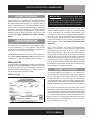
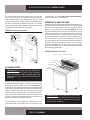
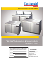
INSTALLATION AND OPERATIONS MANUAL Worktop and Undercounters Worktop/Undercounters & Sandwich Units Refrigerators & Freezers Please fill in the following information for your NEW unit, carefully read the instructions in this manual and file it for future reference. MODEL NO. SERIAL NO. PURCHASED FROM INSTALL DATE 1-800-523-7138 Continental Refrigerator A Division of National Refrigeration & Air Conditioning Products, Inc. 539 Dunksferry Road Bensalem, PA 19020-5908 P 215-244-1400 F 215-244-9579 www.continentalrefrigerator.com Page Receiving Your New Model............................................................................................................................... 3 General Information and Important Operating Facts........................................................................................ 3 Uncrating Your New Model................................................................................................................................ 3 Installation and Location................................................................................................................................... 4 Ventilation............................................................................................................................................ 4 Floor Loads.......................................................................................................................................... 5 Installing Casters and Leveling............................................................................................................. 5 Installing Legs and Leveling................................................................................................................. 6 Condensate Removal............................................................................................................................ 6 Door Adjustment.................................................................................................................................. 7 Hinge Tension Adjustment................................................................................................................... 7 Removal and Replacement of Doors.................................................................................................... 7 Re-Hinging Doors................................................................................................................................. 8 Sandwich Top and Food Pans.............................................................................................................. 8 Initial Cleaning Procedure................................................................................................................................. 9 Start-Up Procedure............................................................................................................................................ 9 Electrical Connections.......................................................................................................................... 9 Start-Up Checklist................................................................................................................................ 9 Remote Applications........................................................................................................................... 10 Operation........................................................................................................................................................... 10 Thermometer....................................................................................................................................... 10 Refrigeration System and Adjustment................................................................................................. 10 Evaporator Assembly........................................................................................................................... 10 Freezer System and Adjustment.......................................................................................................... 11 Defrost Operation.................................................................................................................. 11 Interior Accessories............................................................................................................................. 11 Shelving Installation.............................................................................................................. 11 Maintenance..................................................................................................................................................... 12 Periodic Cleaning Procedure............................................................................................................... 12 General Preventative Maintenance....................................................................................................... 12 Parts and Service.............................................................................................................................................. 13 Optional Accessories........................................................................................................................................ 14 Removal of Drawers and Drawer Adjustments.................................................................................... 14 . Installing Drawer Cage........................................................................................................................ 14 . Installing Overshelf or Double-Overshelf............................................................................................. 15 Installing Stacking Collar Adapter Kit.................................................................................................. 16 Installing Front Breather Kit................................................................................................................. 17 Mounting Caster Support Plates.......................................................................................................... 17 Installing Electric Condensate Heater.................................................................................................. 18 Remote Set-Up and Installation Guidelines......................................................................................... 19 Troubleshooting and Servicing Guide.............................................................................................................. 20 Wiring Diagrams............................................................................................................................................... 22 Limited Extended Protection Warranty............................................................................................................ 24 OPERATIONS MANUAL WORKTOP/UNDERCOUNTERS & SANDWICH UNITS RECEIVING YOUR NEW MODEL Congratulations on your purchase of Continental Refrigerator superior foodservice equipment! When your shipment arrives, thoroughly examine the packaging for any punctures, dents, or signs of rough handling. It is in your best interest to partially remove or open the shipping container in order to examine the contents for any missing accessories, or concealed damage which may have occurred during shipment. If the cabinet is damaged, it must be noted on the carrier’s delivery slip or bill of lading (see “Filing a Damage Claim” under “Warranty” section). GENERAL INFORMATION AND IMPORTANT OPERATING FACTS This manual has been compiled to aid in the installation, operation and maintenance of your new equipment. Please take the time to read it and familiarize yourself with your equipment and its operation, to enjoy optimum performance. Continental Refrigerator offers a variety of accessories for your model (see “Optional Accessories” section towards the back of this manual or contact your dealer for more information). SERIAL DATA TAG A serialized data tag is permanently attached to the inside righthand wall of your unit. (see Figure 1). In addition to identifying the specific product, this label provides important information regarding electrical requirements and refrigeration charge, as well as agency listings and factory contacts. FIGURE 1: Data Tag IMPORTANT NOTE: The model and serial number should be noted on the front cover of this manual, in the spaces provided. If parts or service are ever needed for your unit, this information will be required to verify warranty status and to properly identify any parts that may be needed. All cabinets must be given sufficient time to reach normal operating temperature before placing any food inside cabinet or pans (if equipped). For refrigerators, approximately 1 hour of operation is required to lower the cabinet and pan temperature to 40°F (4°C). During pull-down of open top models, pans should be in place and top lid should be kept closed. Freezers require approximately 2 hours of operation to lower the cabinet temperature to 0°F (-18°C) (see “Operation” section for further information). Prior to factory shipping, all products are performance-run tested for a minimum of 12 hours providing a highly sophisticated temperature recording exclusive to each individual cabinet. This recording is supplied within this manual packet. A final evaluation, including analysis of cabinet performance, leak check, vibration, noise level and visual examination is made by a qualified quality control team to assure a superior product. The carrier signs to this effect when they accept the product for shipping. To insure the maximum in safety and sanitation, all models are listed under the applicable of Underwriters Laboratories and National Sanitation Foundation standards. UNCRATING YOUR NEW MODEL The shipping container should remain on your cabinet to protect against dents or scratches while transporting to the actual set-up location. Remove the shipping container only at the last possible moment by using a pry bar to take out all the staples from around the bottom of the crate. Slide the cardboard carton up and off the unit, being careful not to rub against the cabinet. Remove any accessories or boxes on the skid or in the cabinet. Four (4) bolts secure the cabinet to the wooden skid. The bolts are located at each end on the underside of the skid. In order to remove these bolts, tilt the cabinet backwards and place wooden blocks at each end in order to hold it in its tilted position. Using a ¾” socket or open end wrench, remove the bolts and carefully slide the model off of the skid. After skid removal, the cabinet should never be moved without dollies or rollers to avoid damage to the cabinet bottom or floor. OPERATIONS MANUAL 3 WORKTOP/UNDERCOUNTERS & SANDWICH UNITS IMPORTANT NOTE: Do not under any circumstances, lay your new model on its front or sides. For a brief period of time, you may lay the cabinet on its back, but only when its properly blocked so as not to crush the louvered venting panel and also to allow provision for your hands, in order to set it in its upright position without damaging the cabinet. Do not plug in and operate model for at least three (3) hours after cabinet is set upright from being on its back as this can damage the compressor. INSTALLATION AND LOCATION Before moving the cabinet to its final point of installation, measure all doorways or passages to assure clearance. If additional clearance is needed, you can remove the cabinet doors (see “Removal of Doors and Door Adjustment”) and lids (when equipped) (see “Removing Lid and Hood”). For optimum performance, “SW” series models should be installed on casters or legs (see “Installing Casters” or Installing Legs”) and a mini mum 3” clearance should be provided on each side and the rear of the cabinet (see Figure 2). Your model has been designed to also operate sufficiently without legs or casters and directly on the floor as long as a minimum clearance of 8” is provided from the rear venting louvers and the rear wall (see Figure 2). Cabinet side clearance is not required when mounting your model directly on the floor, without legs or casters. If any of the above conditions can not be achieved, the installer should provide special venting or air supply ducts, or a Front-Breather Kit (see “Optional Accessories”) can be ordered by contacting the factory. “UC” series models and units provided with the Front-Breather Option do not require any clearance around the the sides or back of the cabinet, since they take in and exhaust air under the cabinet and through the front grill, under the door. The air flow under the cabinet and through the front grill cannot be restricted. (see “Front Breather Kit” under “Optional Accessories”). VENTILATION The final location site of your air cooled refrigerator or freezer must provide a large quantity of cool, clean air. All refrigeration systems operate most efficiently and trouble-free with cool, dry air circulation. Avoid locations near heat and moisture generating equipment including ovens, cooking ranges, fryers, dishwashers, steam kettles, etc., or in direct sunlight (where temperatures can exceed 100°F). Do not select a location in an unheated room or area where temperatures may drop below 55°F. Air supply to the condensing unit is equally important. Restricting the air places an excessive heat load on the condensing unit and adversely effect its operation. IMPORTANT NOTE: To assure maximum operating efficiency, your new cabinet should be located where an unrestricted air supply can circulate underneath and behind the cabinet. Do not at any time obstruct the grill area in the rear of the cabinet in any way, and never place or store anything inside of the cabinet machine compartment. These rules are essential for maximum cooling capacity and long life of refrigeration parts. FIGURE 2: Minimum Clearance Dimensions for Optimum Conditions 4 OPERATIONS MANUAL WORKTOP/UNDERCOUNTERS & SANDWICH UNITS FLOOR LOADS The floor at the final location site must be level, free of vibration and strong enough to support the total combined weights of your new model plus the maximum product load which might be placed into it. Keep in mind that all the weight is concentrated at the caster or leg locations. A fully loaded reach-in model may reach 2,000-3,000 pounds. To estimate the possible product weight, assume that each cubic foot of storage space weighs approximately 35 pounds. Multiply 35 pounds by the amount of cubic feet in the cabinet to obtain the product load weight. FIGURE 3: Installing Casters OPTIONAL CASTER SHIM (Reference #CM1-2476) CASTER For example, a 20 cubic foot refrigerator can hold approximately 700 pounds of product (35 x 20). Assuming the cabinet itself weighs 300 pounds, the total combined weight of cabinet and product is approximately 1000 pounds. Therefore, the floor in this example must be able to support up to 1000 pounds. INSTALLING CASTERS AND LEVELING If your new unit is supplied with swivel casters, they will be packed in the accessory box that came with your cabinet. Casters should be installed only when the cabinet is close to it’s final installation site. To install casters on your new model, carefully tip the unit back and position (4) 2” thick wood blocks underneath. Locate the large threaded holes on the bottom of the cabinet and screw the threaded caster studs into the mounting holes, closest to the front of the unit. Repeat this procedure by tilting the cabinet in the opposite direction and installing the remaining casters. Make sure the casters are tightened extremely well (see Figure 3). If the casters are not installed tightly, the cabinet will be unstable and may sway or rock, which can damage the cabinet. If the height of a caster needs to be raised, shims must be installed under the casters which need leveling. Extra large washers, available at most hardware or furniture stores, can be used to shim casters, or contact the factory for caster shims. Do not attempt to level casters by unscrewing them from the cabinet and leaving them loose, as this will cause damage to the cabinet and leg hole threads, voiding all warranties. IMPORTANT NOTE: It is extremely important that your cabinet is perfectly level for proper operation. If it is not level, the following adverse conditions may occur: 1. The door(s) will not be properly aligned and consequently will not provide a good seal. 2. Your unit may run excessively. 3. An excessive amount of ice will accumulate inside the cabinet, around the door opening(s) and on the finned evaporator coil. If allowed to continue, ice will eventually block the coil and the unit will fail. This can result in the loss of all food stored in the cabinet. 4. Defrost water will fail to drain properly and will overflow the evaporator coil drain pan and into the cabinet of both refrigerator and freezer models. OPERATIONS MANUAL 5 04/29/1 WORKTOP/UNDERCOUNTERS & SANDWICH UNITS INSTALLING LEGS AND LEVELING Your new is supplied with adjustable legs for leveling purposes. Each model has four leg mounting holes on the bottom of the cabinet. Legs are packed in the accessory carton from which they must be removed and installed on the cabinet bottom (see Figure 4). In order to install the legs, carefully tip the cabinet back, adding four (4) 2” wood blocks underneath, and simply screw the threaded leg studs into the case bottom front leg holes. Repeat this procedure by tilting the cabinet in the opposite direction and install the remaining legs. Make sure the legs are tightened extremely well or the entire model will sway or rock with each opening or closing of the doors, possibly causing damage to the case bottom. This procedure should be performed close to the final installation site and allow access to the rear of the cabinet for condensate evaporator installation (see “Installing Condensate Evaporator” under “Installation and Location” section). To assure your cabinet is level, all legs are equipped with bullettype leveling bolts. These bolts can be turned by hand or by wrench, clockwise or counterclockwise to level the cabinet. FIGURE 4: Leg Installation THREADED END eliminate water as quickly as possible. The wick has a special antimicrobial coating which minimizes any potential growth of mold or bacteria. The wick pad should be replaced once a year, or if it ever appears clogged or will not retain its shape. In some adverse conditions such as extreme ambient temperature, high humidity, exceptionally heavy usage, frequent loading for prolonged periods of time, or extra heavy pan loading, the amount of condensate water generated could overflow the pan. If this occurs, the plastic drain tube from the cabinet can be diverted directly to a floor drain, bypassing the condensate pan. Alternatively, an optional electric condensate heater may be purchased as an accessory. To install the optional condensate heater, follow the steps for: “Installing Electric Condensate Heater” in the “Optional Accessories” section, located at the back of this manual. (Note: An electric condensate heater is supplied standard on all remote models.) Periodically (at least once a month) the condenser coil should be inspected, to make sure it is not dirty or blocked, and the wick pad can be easily checked at the same time. To check the condenser and wick, disconnect the cabinet power supply, remove the screws securing the back cover to the cabinet and set the parts aside. Inspect the condenser coil and wick pad for any damage or debris. Make sure the wick is secured in the drain pan as shown. Remove any mineral deposits or dirt build up on the condenser, as well as on the wick pad and drain pan. Reattach the back cover and reconnect power to the cabinet. Contact the factory if you need to order a new wick pad or any replacement parts. FIGURE 5: Condensate Pan Location LEG UP TURN END OF LEG COUNTERCLOCKWISE TO INCREASE HEIGHT, OR CLOCKWISE TO REDUCE HEIGHT. CONDENSATE REMOVAL During the refrigeration process, warm, air is cooled and moisture condenses into water which collects in a drain pan in your cabinet. No floor drains or plumbing connections are required for your cabinet, since all models use a self-contained, automatic condensate water evaporating system (see Figure 5). Some models include a wick pad in the drain pan, to maximize evaporation. The pad is made of a composite wicking material with a metallic facing, specifically designed to safely absorb and 6 OPERATIONS MANUAL (when provided) WORKTOP/UNDERCOUNTERS & SANDWICH UNITS DOOR ADJUSTMENT All doors are aligned at the factory, however vibration during transit may cause them to shift and adjustment may be necessary. If a door requires realignment, carefully open the door (90°) and loosen, but do not remove the mounting screws securing both the top (see Figure 6) and bottom (see Figure 8) hinge brackets to the cabinet. Move the door to the desired position by hand or by gently tapping on the edge with a rubber mallet. Hold the door firmly in place and tighten all mounting screws securely, above and below the door. Check alignment and repeat adjustment if necessary. Use a hinge cartridge bracket as a wrench by positioning it upside down with the square hole over the square hub on the spring mechanism (see Figure 7). Carefully turn the square hub on the cartridge in the direction shown to tighten the spring. The mechanism should snap to a neutral position. Remount the hinge as shown and repeat the procedure described above until the hinge snaps back when it is moved from the open-door position towards the closed-door position. FIGURE 7: Spring-Loaded Hinge Mounting FIGURE 6: Hinge Adjustment HINGE TENSION ADJUSTMENT The self-closing doors on your unit have a spring-loaded hinge cartridge concealed in the door (see Figure 7) with a hold-open feature and a cushioned stop. When the door is fully opened (115°) the hinge should be tensionfree. When the door is moved between the open and closed position, the spring-loaded hinge will automatically rotate the door toward the closed position. For proper operation, self-closing doors must be installed with the spring-loaded hinge mechanism set to apply tension in the proper direction (see Figure 8). To adjust spring tension, Open the door fully (115°) so it stays in position when released. Remove the mounting screws securing the cartridge bracket to the cabinet (see Figure 6). The bracket should stay in position when released, but if it is moved or bumped, it may snap into the closed position. THE HINGE CARTRIDGE IS SPRING LOADED AND MAY SNAP BACK ON FINGERS WHEN BRACKET IS LOOSE. WEAR WORK GLOVES AND USE CAUTION WHEN REMOVING MOUNTING SCREWS!! REMOVAL AND REPLACEMENT OF DOORS If you need to remove a door from your cabinet, first identify the location of the spring-loaded hinge cartridge (see Figure 8). Depending on the age of your cabinet, the cartridge is located either on the top or the bottom of the door. CAUTION: THE HINGE CARTRIDGE IS SPRING LOADED AND THE BRACKET MAY SNAP TOWARDS THE DOOR! For doors with spring cartridge on the top: Open the door fully (115°) and remove the mounting screws (see Figure 6) securing the hinge cartridge bracket to the cabinet above the door. (The bracket should stay in the open position, but if it is moved it may snap closed). Pick the door straight up, being careful not to bump the cartridge bracket, and lift it off the pivot pin bracket below the door. To reinstall a door, reverse this procedure and follow the instructions above to set the hinge tension and adjust the door properly. OPERATIONS MANUAL 7 WORKTOP/UNDERCOUNTERS & SANDWICH UNITS For doors with spring cartridge on the bottom: Open the door fully (115°) and remove the mounting screws securing the hinge cartridge bracket to the cabinet below the door. Lower the door down carefully, to avoid bumping the cartridge bracket, and slide it off the pivot pin bracket over the door. To reinstall, reverse this procedure and follow the instructions above to set the hinge tension and adjust the door properly. FIGURE 8: Door Hinge Components “opposite-hand” door (see Figure 8 for parts identification). Follow the steps above, in reverse order. SANDWICH TOP AND FOOD PANS Sandwich units are provided with food pans and divider bars. All pans must be kept in place whenever your unit is operating and lids should be closed whenever possible for optimum performance. To remove the lid over the pans (see Figure 9), lift it 1/2 way up and carefully push in on one end at the bottom corner, so the pivot pin comes out of the mating hole in the hood. Swing the end of the lid forward, so it clears the end of the hood. Slide the entire lid sideways, so the pivot pin on the opposite end is free from the hood. If you have an insulated lid, to remove the liner and insulation, take out the screws along the back edge, let the back of the liner drop down and rotate it so the front edge of the liner disengages from the front of the lid. To remove the hood from the cabinet, take out the screws located inside each end and along the back edge. FIGURE 9: Sandwich Top Lid Open (TYPICAL UNIT WITH 1/6-SIZE PANS SHOWN) LID PIVOT PIN (2) LID HANDLE HOOD FOOD PANS PAN DIVIDERS RE-HINGING DOORS CUTTING BOARD IMPORTANT NOTE: DOORS ARE FIELD REVERSIBLE, BUT DIFFERENT HINGE BRACKETS ARE REQUIRED. HAVE YOUR MODEL & SERIAL NUMBER READY AND CONTACT THE FACTORY FOR THE PARTS NEEDED FOR YOUR UNIT. Remove the door and hinge cartridge bracket from the cabinet, as described above (see Figure 7). Remove the pivot bracket, located at the opposite edge of the door (see Figure 8) by loosening the (2) mounting screws. Remove the hinge cartridge from the door by removing the (2) screws and sliding the cartridge out. Remove the plastic pivot insert from the opposite end of the door by carefully prying it out with a flat-blade screwdriver or putty knife. Remove the remaining “filler screws” from the face of the cabinet and reinstall them in the threaded holes where the brackets were originally mounted. To re-assemble the reverse-hinged door, obtain the correct cartridge bracket and pivot bracket for the top and bottom of the 8 OPERATIONS MANUAL IMPORTANT NOTE: The top opening on your sandwich unit must be completely filled with pans at all times, even if some pans are empty, to maintain air flow for proper cabinet and pan temperature. WORKTOP/UNDERCOUNTERS & SANDWICH UNITS INITIAL CLEANING PROCEDURE Prior to start-up and before placing any product inside of your new model, the interior of the cabinet should be thoroughly cleaned. Washing with a mild soap and warm water solution is recommended for cleaning the aluminum and stainless steel surfaces of your cabinet. This should be followed by cleaning with a baking soda solution (three (3) tablespoons of baking soda to each quart of warm water). Rinse thoroughly with clear water and dry with a clean, soft cloth. IMPORTANT NOTE: Never use harsh detergents, cleaners, scouring powders or chemicals when cleaning your model. Failure to dry the interior surfaces after cleaning may result in a streaking or staining of the metal. Complete cleaning procedures and precautions are listed in the (“Periodic Cleaning Procedure” under the “Maintenance”). START-UP PROCEDURE ELECTRICAL CONNECTIONS To insure proper operation, your new model must be connected to an individual circuit that can supply the full voltage as stated on the cabinet serial data plate. For correct voltage, power draw, and wire accommodations, check the data on the serial data plate located on the inner right wall of your new model. Verify that this information exactly matches the electrical characteristics at the installation location. An electrical wiring diagram, located on the inside compressor compartment rear, next to the electrical console box, should also be consulted during connection. For reference, a copy of each electrical wiring diagram is located towards the back of this manual (see “Wiring Diagrams” section). IMPORTANT NOTE: The condensing unit supplied with all self-contained models is designed to operate with a Rrange of +/-10% of the voltage indicated on the cabinet serial data plate. Full voltage of the correct rating, on an isolated line, not affected by the operation of other electrical appliances, must be available to the refrigeration unit at all times. Burnout of the compressor due to exceeding high or low voltage limits is easily detected and will void the factory warranty. 115 VOLT, 60 HZ, 1 PHASE CONNECTION All 115 volt models are provided with a factory installed, UL approved power cord and polarized plug. To insure proper operation, this equipment must be plugged into a NEMA 5-15 or NEMA 5-20 compatible, grounded receptacle that can supply the full voltage as stated on the serial data plate. WARNING: ANY ALTERATIONS TO THIS CORD AND PLUG COULD CAUSE AN ELECTRICAL HAZARD AND WILL VOID THE FACTORY WARRANTY. SPECIAL VOLTAGE CONNECTIONS When models are ordered from the factory with special, optional voltages, connections should be made as required on the electrical wiring diagram provided on the inside compressor compartment rear next to the electrical console box. START-UP CHECKLIST After your unit has been installed and electrically connected in accordance with this manual, please take time to check the following before loading product, to assure trouble free operation: Sufficient clearance provided (see “Ventilation”) Seperate supply with correct voltage (see “Electrical Connections”) Cabinet level and casters/legs tight (see “Installation and Location”) Doors close and seal properly (see “Door Adjustment”) Proper cabinet temperature (see “System and Adjustment”) Refrigeration lines free of kinks and vibration (see “Refrigeration System”) Condenser and evaporator fans rotate freely (see “Refrigeration System”) Freezers only: Defrost clock set (see “Freezer System and Adjustment”) Pilaster clips secure and shelves level (see “Shelving Installation”) Sandwich Units: All pans and dividers in place (see “Sandwich Top and Food Pans”) All packaging discarded and cabinet cleaned (see “Periodic Cleaning”) OPERATIONS MANUAL 9 WORKTOP/UNDERCOUNTERS & SANDWICH UNITS The system should run smoothly and quietly in accordance with generally accepted commercial standards. If any unusual noises are heard, turn the unit off immediately and check for any obstructions of the condenser or evaporator fans. Fan motors, fan blades, or fan housings can be jarred out of position through rough handling in transit or during installation. CAUTION: IF UNIT IS UNPLUGGED OR DISCONNECTED FOR ANY REASON, ALLOW 5-6 MINUTES BEFORE TURNING THE UNIT BACK ON TO ALLOW THE SYSTEM TO EQUALIZE. DISREGARDING THIS PROCEDURE COULD CAUSE AN OVERLOAD AND PREVENT THE UNIT FROM OPERATING. REMOTE APPLICATIONS All models are available for purchase as remote models in which case the condensing unit is purchased separately and installed at the time of installation. All remote models are equipped with an expansion valve located within the evaporator coil housing, and both liquid and suction lines stubbed and extending out from the cabinet rear behind the rear cover. Installation of the refrigeration accessories, condensing unit, and electrical hookup should be performed by qualified refrigeration personnel of a competent refrigeration company only (see “Remote Set-Up and Installation Guidelines” under “Optional Accessories”). to 4.4°C). The temperature control is accessible inside of the cabinet product compartment, on the right back wall next to the evaporator coil (see Figure 10). If an adjustment is necessary to maintain temperature within the range noted above, place a screwdriver into the thermostat slot and turn clockwise for a colder cabinet temperature or counterclockwise for a warmer cabinet temperature. Further adjustments out of the factory design temperature range should only be made by a qualified refrigeration mechanic. IMPORTANT NOTE: Turning a thermostat fully counterclockwise turns the refrigeration compressor “off.” EVAPORATOR ASSEMBLY All undercounter refrigerators and freezers have an easily accessible, easily serviceable, performance-rated, forced-air evaporator assembly which utilizes a plasticized fin coil for extended life. All models utilize a full length, extra large evaporator coil with a uniquely directed air flow distribution which keeps compartment product at uniformly constant temperatures (see Figure 10). FIGURE 10: Evaporator Assembly OPERATION All cabinets must be given sufficient time to reach normal operating temperature before placing any product in cabinet. Refrigerators are designed to maintain cabinet temperature of 38° to 40°F (3.3° to 4.4°C), about 1 hour of operation is required to reach this temperature. Food pans in sandwich tops must be kept in place at all times and lids should be kept closed whenever possible. Freezers are designed to maintain an ideal cabinet temperature of -4° to 0°F (-20° to -18°C), about 2 hours of operation is required to reach temperature. THERMOMETER Your new model has a non adjustable hanging thermometer located inside the cabinet, mounted on the coil housing cover (see Figure 10). This thermometer is maintenance-free and needs no further calibration. REFRIGERATION SYSTEM AND ADJUSTMENT All self-contained refrigerators are designed and factory set to maintain an average cabinet temperature of 38° to 40°F (3.3° 10 OPERATIONS MANUAL IMPORTANT NOTE: All refrigerators are designed with an automatic, “off-cycle” defrost system which means that defrosting occurs automatically when the compressor is not operating during an off-cycle. Do not set the thermostat too cold where the cabinet temperature will fall below 35°F (1.7°C) because the evaporator will become blocked by ice since the compressor off-cycle will be considerably shortened. This will result in loss of product stored within the cabinet and require service to defrost the evaporator and re-adjust the thermostat. 06/02/10 WORKTOP/UNDERCOUNTERS & SANDWICH UNITS FREEZER SYSTEM AND ADJUSTMENT All self-contained sandwich unit freezers are designed and factory set to maintain an average cabinet temperature of -4° to 0°F (-20° to -18°C). All freezers are designed for the purpose of holding pre-frozen product and although they are capable of freezing small quantities of fresh product, they are not designed to be blast chillers or ice-cream freezers. Do not attempt to freeze bulk quantities of fresh food or ice-cream. The temperature control is accessible inside of the cabinet product compartment, on the right back wall next to the evaporator coil (see Figure 10 for thermostat location). If an adjustment is necessary to maintain the above temperature range only, place a screwdriver into the thermostat slot and turn clockwise for a colder cabinet temperature or counterclockwise for a warmer cabinet temperature. Further adjustments out of the factory design temperature range must be made by a qualified refrigeration mechanic only. FIGURE 11: Defrost Timer DEFROST TIMER INTERIOR ACCESSORIES IMPORTANT NOTE: Turning a thermostat fully counterclockwise turns the refrigeration compressor “off.” Your new unit is shipped with (1) shelf per section and (4) pilaster clips for each shelf. DEFROST OPERATION All freezer models are equipped with an automatic, electric defrost system consisting of electric evaporator coil and drain pan heaters, a defrost time clock and an automatic defrost limit switch. The defrost system is time initiated by the time clock and temperature terminated by the automatic limit switch. The time clock is preset for three (3) defrost periods per day at eight (8) hour intervals and a fail safe cut-off time of 20 minutes. Please note that defrost settings are not programmable. SHELVING INSTALLATION Pilaster strips which support the shelving are secured to the cabinet walls with special pilaster screws which allow the strips to be readily removed for cleaning without the use of tools. Shelf clips are easily installed by inserting them into the pilasters at the desired shelf location and shelf installation is as simple as placing the shelf on the (see Figure 12). The defrost time clock is located in front of the electrical console box in the rear machine compartment of your freezer (see Figure 11). If desired, to pre-set the initiation of the defrost cycle to the time of day on the defrost time clock, turn the knob on the center dial of timer face clockwise until the unit defrost cycle begins (compressor and all fans will terminate). Defrost will begin at this same time every day at eight (8) hour intervals. For example, if an 8:00 am defrost is desired, at 8:00 am turn the defrost manual set knob to initiate defrost and a defrost cycle will start every day at 8:00 am, 4:00 pm, 12:00 am. It will be necessary to reset the time of defrost on the timer if the freezer is turned off or has loss of power. FIGURE 12: Standard Shelf Pilaster SHELF INSTALLING PILASTER STRIP PILASTER CLIP INSTALLED PILASTER CLIP INSTALLING OPERATIONS MANUAL 11 WORKTOP/UNDERCOUNTERS & SANDWICH UNITS MAINTENANCE return electric supply power to the model. PRECAUTIONS NEVER USE HARSH DETERGENTS, CLEANERS, SCOURING POWDERS, OR CHEMICALS WHEN CLEANING YOUR UNIT. STRONG BLEACHES TEND TO CORRODE MANY MATERIALS AND SHOULD NEVER COME IN CONTACT WITH STAINLESS STEEL. TINCTURE OF IODINE OR IRON SHOULD NOT COME IN CONTACT WITH STAINLESS STEEL. THESE SOLUTIONS, WHICH CAUSE STAINLESS STEEL TO DISCOLOR, SHOULD BE RINSED OFF IMMEDIATELY IF CONTACT OCCURS. GRITTY, HARD ABRASIVES WILL MAR THE FINISH OF STAINLESS STEEL AND ALUMINUM AND ARE NOT RECOMMENDED. SAFETY PRECAUTIONS THE FOLLOWING SAFEGUARDS SHOULD BE FOLLOWED WHEN OPERATING ANY APPLIANCES: DISCONNECT THE POWER CORD BEFORE ATTEMPTING TO WORK ON OR CLEAN EQUIPMENT. DISCONNECT POWER WHEN THE APPLIANCE WILL BE IDLE FOR A LONG PERIOD OF TIME. DO NOT ATTEMPT TO REMOVE ANY COVERS OR PARTS YOURSELF, AS THIS CAN EXPOSE DANGEROUS, HIGH VOLTAGE WIRING. SERVICE SHOULD ONLY BE PERFORMED BY A QUALIFIED TECHNICAIN. ALWAYS ROUTE POWER CORDS AWAY FROM AREAS WHERE THEY CAN BE WALKED ON OR DAMAGED BY OTHER EQUIPMENT. NEVER USE EXTENSION CORDS OR PLUG MORE THAN ONE APPLIANCE INTO THE SAME CIRCUIT. THIS CAN OVERLOAD THE POWER SUPPLY, WHICH CAN RESULT IN ELECTRICAL SHOCK OR FIRE. YOUR APPLIANCE IS EQUIPPED WITH A POLARIZED, GROUNDED POWER PLUG. NEVER ATTEMPT TO REMOVE THE GROUND POST OR USE A NON-POLARIZED ADAPTER, WITHOUT PROPERLY GROUNDING THE EQUIPMENT. IF A REPLACEMENT PART IS REQUIRED, ALWAYS INSIST ON FACTORY AUTHORIZED COMPONENTS. PERIODIC CLEANING PROCEDURE It is best to clean your refrigerator or freezer when the product load in your cabinet is as its lowest level. To clean the interior or exterior cabinet surfaces, follow these procedures: 1. Disconnect your model from its power supply and remove all product from inside. 2. Open all doors and allow the cabinet to reach room temperature. Remove all accessories (shelves, racks, pilasters, clips, etc.) from within the model, wash with a baking soda and warm water solution, and rinse thoroughly with clear water. Dry all of the accessories completely with a soft clean cloth. 3. Once the cabinet has reached room temperature, wash the inside and outside with a solution of warm water and baking soda. For slightly more difficult cleanups, ammonia or vinegar in warm water can be used. Rinse thoroughly with clear water and dry with a soft clean cloth. Failure to dry all surfaces completely may cause water stains or streaking on the aluminum or stainless steel finish. 4. Return all accessories to their respective positions and 12 GENERAL PREVENTATIVE MAINTENANCE Performance of the air cooled condensing unit located inside of the compressor machine compartment of your new model, depends exclusively upon the amount of air passing through the condenser fins. Your refrigerator or freezer will run more efficiently, consume less current, and provide a maximum of trouble-free service throughout its lifetime if the condenser is kept clean and an adequate supply of clean, cool air is provided at all times. Periodically (at least once a month) inspect the condenser coil, which is located directly behind the rear panel grill, to check for debris or blockage (see Figure 13). If the condenser coil is dirty or blocked, disconnect the power supply to your model and using a stiff brush, brush the dirt from the condenser fins until the condenser is clear from any debris. Using a vacuum cleaner with a brush attachment may aid in this cleaning process. After cleaning, restore electrical service to your model. ACCESSING CONDENSER COIL FOR CLEANING FIGURE 13: Accessing Coil Condenser OPERATIONS MANUAL REMOVE SCREWS AT BOTTOM OF BACK PANEL AND SLIDE DOWN TO REMOVE CONDENSER COIL WORKTOP/UNDERCOUNTERS & SANDWICH UNITS PARTS AND SERVICE Continental Refrigerator is committed to providing the best customer service in the industry. All new units come with a Limited Extended Protection Warranty (see “Warranty” section). If a problem arises with your equipment, please contact our Service Department at 1-800-523-7138 (extension 3301, 3302, or 3303). One of our Service Specialists will do everything possible to solve the problem as quickly as possible. ITEMS NOT COVERED UNDER WARRANTY INCLUDE, BUT ARE NOT LIMITED TO: • Preventative maintenance: cleaning condenser coils and other components. • Consumables: light bulbs, door gaskets, fuses and batteries. • General hardware adjustments: cabinet leveling, casters/legs, doors/hinges. • Problems due to: inadequate installation or supply power; improper maintenance, operation, or abuse. • Compressor failure due to: dirty condenser, insufficient clearance/ventilation, excessive temperatures. • System adjustments and calibrations, including: temperature control, thermometer and expansion valves. Consult the Table of Contents in the front of this manual for detailed information on the items listed above. Contact Continental’s Service Department with any additional questions. PLACING A SERVICE CALL In order to receive prompt service, always be prepared to provide your: cabinet model and serial number; cabinet location name and date installed; contact name and phone number; plus a description of the problem. During normal business hours (Monday to Friday, 8am to 5pm Eastern) contact the Service Department at: 1-800-523-7138 (extension 3301, 3302, or 3303) prior to any warranty service work being performed. After normal business hours, or on weekends, notify our Service Department by sending an email to: [email protected], or leaving a voice message at: 1-800-523-7138 (extension 3301). Be sure to provide the information listed above. Contact Continental the following business day, during normal business hours, to verify the status of your call. OBTAINING REPLACEMENT PARTS UNDER WARRANTY If replacement parts are required for a unit under warranty, contact Continental’s Service Department. New parts will be sent from the factory and, when applicable, a Return Goods Authorization (RGA) number will be provided to return old parts. The RGA number must appear on the packaging of any parts returned, or they will not be accepted. If a service agent uses a part from their stock, Continental will replace it with a factory part. OBTAINING REPLACEMENT COMPRESSOR UNDER WARRANTY If the compressor should fail within the first twelve (12) months of use, or within twenty (20) months from the date code on the compressor, an “over-the-counter” exchange must be made at an authorized Copeland, Danfoss, Embraco, or Tecumseh wholesaler. After the first year of operation, the compressor motor is covered under an extended “parts only” warranty. The customer is responsible for any labor charges and any additional parts that may be required. Contact the Service Department to obtain a replacement compressor through one of the following methods: • Continental will supply a replacement compressor at no charge and pay for regular freight. (If expedited freight is requested, the end user, dealer or service agent is responsible for additional freight charges and must provide credit card information. • A compressor can be purchased locally and Continental will either replace the stock unit with a new factory compressor, or offer an allowance towards the purchase of a replacement compressor, up to: $100 for 1/5hp to 1/3hp; $250 for 1/2hp to 3/4hp; $350 for 1hp to 2hp. The data tag from the defective compressor (or the compressor model, serial number and date code, if the tag cannot be removed) must be included with any request for reimbursement. OPERATIONS MANUAL 13 WORKTOP/UNDERCOUNTERS & SANDWICH UNITS FIGURE 14: Drawer Slide OPTIONAL ACCESSORIES Continental offers a variety of accessories for your unit. LEFT-HAND SHOWN (RIGHT-HAND OPPOSITE) REMOVAL OF DRAWERS AND DRAWER ADJUSTMENTS To remove the drawers from the cabinet, slide each drawer out until it stops. Unhook the stop clip at the front of the left and right-hand drawer slide (see Figure 14) by pushing the clip forward and pressing down on the top back edge as shown. Lift the drawer slightly as you pull it the rest of the way out. The center member, with the wheels attached, will remain in the cabinet. To remove a drawer center member for cleaning or maintenance, pull it out and push up on the release lever at the back, as shown. To install a drawer, identify the correct parts and orient the center members so the plastic clips are in the front and at the top. Insert one of the center members into the front of the correct cabinet member (which is permanently attached to the inside of the cabinet) and slide it in, until it stops. Push up on the release lever (located toward the rear and top of the center member) to allow the center member roll the rest of the way into the cabinet member, in the “drawer closed” position. Repeat for the opposite side center member. Pull each center member out a few inches, press down on the rear of each stop clip, and pull forward so the hook on the front of the clip rotates up, into the “unlocked” position. Lift the drawer body into place, resting the drawer members (the channels welded to the sides of the drawers) on the front wheels of the center member, and slide the drawer into the cabinet. Once the drawer goes in all the way and slides smoothly, open it enough to access the stop clips. Lift the back of each clip and push in at the front, so the hook portion snaps into the “locked” position. The drawers are now secured, so they cannot accidentally be lifted out of the cabinet. Check that the drawer is properly aligned, rolls smoothly and the drawer gasket seals firmly. If the drawer fronts needs adjustment (once all drawers are installed and closed), loosen the five screws that hold the drawer front to the drawer body. Move the drawer front into position desired and re-tighten all screws. 14 SLIDE CLIP FORWARD & PRESS HERE TO DISENGAGE PUSH UP ON LEVER TO DISENGAGE CABINET MEMBER RELEASE LEVER STOP CLIP DRAWER MEMBER (EXPLODED VIEW) CENTER MEMBER INSTALLING DRAWER CAGE To convert your cabinet from doors to drawers, you will need a drill with a 1/8” bit, a Phillips bit (or a Phillips-Head screwdriver (or drill/driver with Phillips bit), and a rubber mallet. Take the door off the section you want to convert, by following instructions in the “Removal of Doors” section of this manual. Take the drawers out of the mounting cage, by following instructions in the “Removal of Drawers” section of this manual. Position the drawer mounting cage in front of the cabinet opening as shown (see Figure 16). Lift the cage above the trim along the bottom of the opening, so it is aligned to go straight into the cabinet. Carefully slide the drawer cage into the unit opening. It is a snug fit and some pressure may be need to be applied at the corners, to clear the breaker around the opening. A rubber mallet can be used to gently tap on the ends of the drawer cage cross mullion, to force the fasteners past the side breakers. The straighter the cage is pushed in, the easier it will be to install. When the cage is in as far as it will go, the notches at the front of the cage should surround the breaker corners at the bottom. The face of the drawer cross mullion should be relatively flush with the front face of the cabinet, to provide an even surface for the drawer gaskets to seal properly around the openings. The cage should sit relatively flat on the floor and against the back wall step inside the cabinet. OPERATIONS MANUAL WORKTOP/UNDERCOUNTERS & SANDWICH UNITS With the cage properly in place, use the holes along the front sides of the cage assembly as a template to drill (6) 1/8” pilot holes through side breakers and the metal underneath. Drive a sheet metal screw into each of the front mounting holes, securing the front of the cage to the inside of the opening, and tighten them snugly, without stripping the screws or the pilot holes. Drive a sheet metal screw through each of the two slots located at the lower the rear of the cage and into the back wall step of the Cabinet. IMPORTANT NOTE: These screws should NOT be tight! The purpose of these screws is to limit the side-to-side movement of the rear of the cage, not to rigidly secure the cage to the cabinet. To re-install the drawers into the cabinet, follow the instructions in the “Removal of Drawers” section of this manual. Note that the top drawer slides are longer than the bottom slides. FIGURE 16: Drawer Cage CAGE MOUNTING HOLES BREAKER CORNERS INSTALLING OVERSHELF OR DOUBLE-OVERSHELF IMPORTANT NOTE: Installing an overshelf is a two-person job. Due to the weight, size and height of the shelf, do not attempt to mount it alone, as this can cause injury. To mount an overshelf to your cabinet, a phillips-head screwdriver (or a screw gun with phillips bit) is required. Before starting to assemble the overshelf, identify the following parts provided: ¼-20 screws, 10-32 screw, uprights, top shelf, and bottom shelf (for double overshelves only). If applicable, determine the height you want the bottom to be located. IMPORTANT NOTE: There are three pairs of holes provided in the iprights, so the shelf can be installed at a height of 19”, 21”, or 23” above the top of the cabinet. This height will also determine the distance between the bottom shelf and the top shelf (13”, 15”, or 17”). From the back of your cabinet, locate the two holes with threaded inserts at each end of the Cabinet. (see Figure 17) Drive a ¼-20 screw into each of the (4) threaded inserts, until the bottom of the screw head is about ” away from the threaded insert. Position the uprights at the back of the cabinet. Noting that there are two keyhole slots on one face of each upright, locate the keyholes at the bottom, facing the screws you just installed in the cabinet. Lift the upright and place the large portion of the keyhole slots over the screw heads and then lower it on to the screws. Insert a philips screwdriver through the clearance holes, on the opposite side of the keyhole slots (in the rear of the uprights). Tighten the screws just until the upright is snug against the unit, but leave a little play for alignment. Repeat this procedure for the other upright. SLOT NOTCHES WILL BE SURROUNDING BREAKER CORNERS CROSS MULLION FASTENERS To install a double overshelf (for single overshelf, skip to the next paragraph) locate the bottom shelf, which has a large hole in each rear corner. With one person holding each end of the shelf, lift it above the top of the uprights and align it so the large holes in the rear of the shelf fit over the uprights. Carefully slide the shelf down, until the small holes on back of the shelf line up with the correct holes in the uprights, depending on the shelf height desired. Attach the shelf to the uprights, using two 10-32 screws on each end. Drive the screws until snug, but do not tighten them completely. With one person supporting each end of the top shelf, list it into position above the uprights and lower it down onto them. Secure the shelf, using two 10-32 screws on each end, driving OPERATIONS MANUAL 15 WORKTOP/UNDERCOUNTERS & SANDWICH UNITS them snugly but not tightly. Check the alignment of the shelves and tighten all the screws. Double check that the shelves and uprights are secured rigidly. FIGURE 17: Overshelf Installation TOP SHELF (NO NOTCHES IN BACK CORNERS) 10-32 SCREWS BOTTOM SHELF all rear screw hole slots line up on both top and bottom models where screws were removed from in Step 2. If screw hole slots do not line up (left to right) with screw holes then the stacking collar has been mounted upside down. Remove and re-install correctly. 5. Adjust the height and level of the “top” cabinet by reaching in through the front opening of the stacking collar and turning the bullet feet on the legs in (CW) until the bottom of the cabinet is snug against the stacking collar. Once snug, install the rear screws that were removed in Step 2 and peel off the adhesive tape backing strip around the side flanges of the stacking collar so that both units are bonded together. 6. Align the front grill holes with the stacking collar holes and secure both thumbscrews. UPRIGHT FIGURE 18: Stacking Collar 1/4-20 SCREWS KEYHOLES OPPOSITE THESE HOLES INSTALLING STACKING COLLAR ADAPTER KIT All models that are 48” wide or less and have a solid, flat top can be stacked one on top of the other with the use of a heavy duty, stainless steel stacking collar as shown in Figure 18. When stacking a refrigerator and freezer, it is always best to place the freezer model on the bottom for maximum efficiency. The front grill which is attached to the stacking collar body is attached with easily removable thumbscrews and should be removed periodically for cleaning. The front grill should always be clean and clear of debris and never blocked. STACKING COLLAR GRILL To stack your models, the following instructions should be followed: 1. Decide which unit is to be on “top” & “bottom”. 2. On “top” unit, remove screws at the bottom of the back cover. In “bottom” unit, remove screws, joggle clips and bumpers aloing the top back of the cabinet. 3. Install the legs on the “top” unit and adjust all four bullet feet out (CCW) three full turns. Carefully lift the cabinet and set it on top of the “bottom” unit. 4. Install stacking collar as shown in Figure 18, making sure 16 OPERATIONS MANUAL WORKTOP/UNDERCOUNTERS & SANDWICH UNITS INSTALLING FRONT BREATHER KIT (Skirt and Grill) IMPORTANT NOTE: You may CAREFULLY lay the cabinet on it’s back, but only FOR A BRIEF PERIOD OF TIME. Caution must be taken to ensure you DO NOT DAMAGE the louvered back panel, refrigeration system components, or copper tubing located behind the panel. The cabinet must be properly blocked, to allow room to get your hands in to lift without damaging the cabinet or crushing the vents on the back panel. DO NOT PLUG-IN OR OPERATE THE REFRIGERATION SYSTEM FOR AT LEAST THREE (3) HOURS AFTER THE UNIT HAS BEEN RETURNING IT TO AN UPRIGHT POSITION, AS THIS CAN DAMAGE THE COMPRESSOR. Position the left hand air duct/skirt (see Figure 19) as shown. Attach the front left caster by inserting threaded end through the slot in the air duct/skirt and screwing it into the threaded hole in the bottom of the cabinet. Do not tighten completely. Repeat for the back left caster. Follow these steps for the right hand air/duct skirt and remaining casters. Position the front grill as shown and attach it to the front edge of the air duct/skirts using the thumbscrews provided. Adjust the position of the air duct/skirts and the front grill as needed. Tighten the thumbscrews and all 4 casters completely. Carefully lift the cabinet upright and check that the grill and casters are secure. Your refrigerator or freezer is now front breathing and can be completely enclosed on the sides, back and top. The refrigeration system will take in fresh air through one side of the front grill, pull it under the cabinet, through compressor compartment to cool the condenser, back out under the cabinet and exhaust it through the other side of the front grill. ANY RESTRICTIONS TO THE AIR FLOW THROUGH THE FRONT GRILL OR UNDER THE CABINET CAN DAMAGE THE REFRIGERATION SYSTEM AND WILL VOID ALL WARRANTIES. FIGURE 19: Front Breather Kit (2) THUMBSCREWS FRONT GRILL LEFT HAND AIR DUCT/ SKIRT NOTE: INSTALL AIR DUCT/SKIRTS WITH CUT-OUTS TOWARD BACK OF CABINET (4) 3" CASTERS RIGHT HAND AIR DUCT/ SKIRT MOUNTING CASTER SUPPORT PLATES If the standard stem casters on a cabinet are not properly maintained and tightened, or if the unit is excessively overloaded and moved around, the threaded inserts in the bottom of the cabinet can become stripped, twisted or collapsed. If this occurs and the stem casters cannot be mounted securely, rigid caster support plates can be fitted to provide the strength needed to safely use your cabinet. Each caster support plate assembly is made of heavy gauge galvanized steel, with (2) casters permanently welded to it, for maximum rigidity. The plate has a series of holes that will allow you to fasten the plate assembly to the bottom of the cabinet with sheet metal screws and bolts. Contact the factory to obtain the correct parts for your model. IMPORTANT NOTE: Always wear proper work gloves and use appropriate safety equipment. You may CAREFULLY lay the cabinet on it’s back, but only FOR A BRIEF PERIOD OF TIME. Caution must be taken to ensure you DO NOT DAMAGE the louvered back panel, refrigeration system components, or copper tubing located behind the panel. The cabinet must be properly blocked, to allow room to get your hands in to lift without damaging the cabinet or crushing the vents on the back panel. DO NOT PLUG-IN OR OPERATE THE REFRIGERATION SYSTEM FOR AT LEAST THREE (3) HOURS AFTER THE UNIT HAS BEEN RETURNING IT TO AN UPRIGHT POSITION, AS THIS CAN DAMAGE THE COMPRESSOR. OPERATIONS MANUAL 17 WORKTOP/UNDERCOUNTERS & SANDWICH UNITS To install caster support plate assemblies, you will need a 3/4” open end wrench (or a large adjustable wrench), a drill with a 1/8” bit and a Phillips bit (or a Phillips-Head screwdriver) plus work gloves. A 1/2-13 thread tap is also recommended, to repair any damage to the threaded inserts in the cabinet. Unload all product and carefully lay the cabinet on its back. Remove the old stem casters by unscrewing them from the cabinet. If a caster or threaded insert has been stripped or cross-threaded, it may be necessary to use a wrench to loosen the caster. Hold one of the support plate assemblies under the cabinet as shown (see Figure 20). Position it so the slotted holes at the end of the plate line up with the threaded inserts in the bottom of the cabinet (where the stem casters were attached). Attach the plate assembly to the cabinet by putting a 1/2” x 1-3/4” long bolts and flat washer through the slot in the support plate and screwing into each of the threaded inserts in the bottom of the cabinet. Snug the bolts down, but do not tighten them completely. If one of the threaded inserts is stripped or damaged, a thread tap should be used to clean the threads. FIGURE 20: Caster Support Plates Secure the caster support plate assembly to the cabinet with a sheet metal screw in each of the drilled holes. Tighten the 1/2” bolts. Repeat these steps to attach the other plate assembly to the opposite end of the cabinet. Check that both plates are secure and that the casters turn and swivel freely. Carefully lift the cabinet upright and double check that the caster support plates are secure and the cabinet is stable. Wait at least 3 hours before turning the refrigeration system back on, and at least another 30 minutes for the cabinet to come down to temperature and stabilize, before reloading with product. INSTALLING ELECTRIC CONDENSATE HEATER The electric condensate heater has a thermal limit switch and power cord attached. To install the heater, remove the screws securing the back cover to the cabinet (see Figure 21) and set the cover aside. Place the vaporizer heater in the drain pan as shown and carefully position the end of the plastic drain tube in the pan. Make sure the tubing is not kinked and the end is located securely in the pan, so it does not touch the heating element. Plug the power cord from the heater into the receptacle labeled “vaporizer” on the lower back wall of the cabinet. Secure any excess power cord with a wire tie, so it does not fall into the pan or under the cabinet. Reattach the cover to the back of the cabinet. FIGURE 21: Electric Condensate Heater BOTTOM OF CABINET REMOVE OLD STEM CASTERS FLAT WASHER (2 PER PLATE) 1/2-13 BOLT (2 PER PLATE) SUPPORT ASSEMBLY WITH PLATE CASTER Using the small holes in the plate as a template, drill 1/8 pilot holes in the bottom of the cabinet. (Note: drill only until you penetrate the metal bottom of the cabinet. Do not continue to drill into the insulation, or you may damage the cabinet.) 18 OPERATIONS MANUAL WORKTOP/UNDERCOUNTERS & SANDWICH UNITS REMOTE SET-UP AND INSTALLATION GUIDELINES All remote refrigerators and freezers are shipped with an expansion valve, thermostat and defrost timer (freezer only), installed from the factory. The installer is responsible for connecting all refrigerant lines, liquid line drier, sight glass, solenoid, head pressure control, hi/low pressure safety, crankcase heater, condensing unit and any other accessories as well as wiring. The evaporator section has been factory leak checked with helium, however; due to vibration in transit, the entire system must be thoroughly leak checked after installation and prior to start-up. The final leak inspection of the entire completed refrigeration system and all of its components as well as start-up and the operation of the refrigeration system is the sole responsibility of the installer. The CFC-Free refrigerant used in standard remote and self-contained models is R-134a for refrigerators and R-404a for freezers. All compressors and systems designed for these refrigerant utilize polyolester oil as their main lubricant, which absorbs moisture from the ambient surroundings extremely fast and in much greater quantity than conventional mineral oils. Since moisture levels greater than 100 PPM will result in system corrosion and ultimate failure, it is imperative that the compressor, components and entire system be kept sealed. large pressure differential between the system and the vacuum pump. System must be evacuated from both high and low sides of the system using heavy duty vacuum hoses. 6. Each system should be charged with the refrigerant type as specified on the cabinet data tag. This refrigerant type should match the type listed on the condensing unit being used. The refrigerant charge should be held to the minimum required for the satisfactory pull down and operation. For an accurate indication of refrigerant charge, the sight glass will show a full column of liquid. 7. The superheat reading taken 6” from the compressor suction valve should be 30° +/- 5°. Expansion valve adjustment may be necessary to achieve this superheat. 8. Installation of the electric condensate heater is also the responsibility of the installer (see “Installing Electric Condensate Heater” under “Optional Accessories”). CAUTION: EXTREME CARE MUST BE USED WHEN ACCESSING THE SYSTEM DURING INSTALLATION. DUE TO THE COMPLEXITY OF REMOTE REFRIGERATION SYSTEMS AND THE POTENTIAL FOR IMPROPER INSTALLATION, ANY RESTRICTIONS, LEAKS, FAILED OR DAMAGED COMPONENTS CAUSED BY CONTAMINANTS ARE NOT THE RESPONSIBILITY OF CONTINENTAL REFRIGERATOR. 1. All refrigerant lines and components must be clean, free of burrs and purged with nitrogen prior to and during brazing or soldering connections. Nitrogen purging during brazing or soldering will eliminate carbon or foreign matter contamination. Any system restrictions or contamination is the responsibility of the installer. 2. Condensing unit or compressor shall not be left open to the atmosphere for more than five (5) minutes. 3. No refrigeration component, tubing or fitting shall be left open to the atmosphere for more than ½ hour without being soldered, capped or plugged. 4. Each completed refrigeration system shall be purged with 150psi of dry nitrogen for at least six (6) seconds, then pressurized with at least 165psi of nitrogen for pressure check (making sure to energize any solenoid valves to assure access). Leak-check all joints, flare fittings and valves and make sure there is no pressure drop within the system. 5. System evacuation is of the utmost importance with NONCFC refrigerant systems. System must be evacuated to a minimum of 200 microns. In addition, a vacuum decay test is strongly recommended to assure there is not a OPERATIONS MANUAL 19 WORKTOP/UNDERCOUNTERS & SANDWICH UNITS TROUBLESHOOTING GUIDE PROBLEM PROBABLE CAUSE Condensing unit will not start - no hum. 1. 2. 3. 4. 5. 6. Condensing unit will not start - hums but trips on overload protector. 1. 2. 3. 4. 5. Condensing unit starts and runs, but short cycles on overload protector. CORRECTION 1. 2. 3. 4. 5. 6. Close start or disconnect switch. Replace Fuse. Determine reason and correct/replace. Relocate control. Repair or replace control. Check wiring against diagram. Improperly wired. Low voltage to unit. Starting capacitor defective. Relay failing to close. Compressor motor has a shorted or open winding. 6. Internal mechanical trouble in compressor. 7. Insufficient air supply. 1. 2. 3. 4. 5. Check wiring against diagram. Determine reason and correct. Determine reason and replace. Determine reason and replace. Replace compressor. 1. Additional current passing through overload protector. 1. Check wire diagram. Check for added components connected to wrong side of overload protector. 2. Determine reason and correct. 3. Check current, replace protector. 4. Determine reason and replace. 5. Check ventilation, restrictions in cooling medium or refrig. system. 6. Check for misapplication. 7. Clear condenser and allow compressor to cool down. 2. 3. 4. 5. Line disconnected, switch open. Fuse removed or blown. Overload protector blown. Control “Off” due to cold location. Control stuck in open position. Wiring improper or loose. Low voltage unit. Overload protector defective. Run capacitor defective. Excessive discharge pressure. 6. Excessive suction pressure. 7. Insufficient air supply. Condensing unit starts, but fails to switch off of “start” winding. 1. 2. 3. 4. 5. Improperly wired. Low voltage to unit. Relay failing to open. Run capacitor defective. Excessively high discharge pressure. 6. Replace compressor. 7. Clear condenser and allow compressor to cool down. 1. 2. 3. 4. 5. 6. Compressor motor has a shorted or open winding. 7. Internal mechanical trouble in compressor. Check wiring against diagram. Determine reason and correct. Determine reason and replace. Determine reason and replace. Check discharge shut-off valve, possible overcharge. 6. Replace compressor. 7. Replace compressor. Condensing unit runs, but short cycles on: 1. Overload protector. 2. Thermostat. 3. High pressure cut-out due to: (a) Insufficient air supply. (b) Overcharge. (c) Air in system. 4. Low pressure cut-out due to: (a) Valve leak. (b) Undercharge. (c) Restriction in expansion device. 1. See Problem 3 2. Differential must be widened. 3. (a) Check air supply to condenser. (b) Evacuate and re-charge. (c) Evacuate and re-charge. 4. (a) Replace, evecuate and re-charge. (b) Evacuate and re-charge. (c) Replace expansion device. Condensing unit runs, but for prolonged periods or continuous. 1. 2. 3. 4. Shortage of refrigerant. Control contacts stuck closed. Excessive heat load placed into cabinet. Prolonged or too frequent door openings. 5. 6. 7. 8. Evaporator coil iced. Restriction in refrigeration system. Dirty condenser. Filter drier clogged. 1. Fix leak, evacuate and re-charge. 2. Clean contacts or replace control. 3. Allow unit sufficient time for removal of latent heat. 4. Plan or organize schedule to correct condition. 5. Defrost evaporator coil. 6. Determine location and remove. 7. Clean condenser coil. 8. Replace, evacuate and re-charge. 20 OPERATIONS MANUAL WORKTOP/UNDERCOUNTERS & SANDWICH UNITS TROUBLESHOOTING GUIDE PROBLEM Start capacitor open, shorted or blown. PROBABLE CAUSE CORRECTION 1. Relay contact not opening properly. 2. Prolonged operation on start cycle: (a) Low voltage to unit. (b) Improper relay. (c) Starting load too high. 3. Excessive short cycling. 4. Improper capacitor. 1. Clean contacts or replace relay. 2. (a) Determine reason and correct. (b) Replace with correct relay. (c) Correct by using pump down. 3. Determine reason for short cycle, see Problem 5 and correct. 4. Determine correct size and replace. Run capacitor open, shorted or blown. 1. Improper capacitor. 2. Excessively high line voltage, over 110% of rated maximum. 1. Check size and replace. 2. Determine reason and correct. Relay defective or blown out. 1. 2. 3. 4. 5. 6. 7. 1. 2. 3. 4. 5. 6. 7. Product zone temperature too high. 1. Control setting too high. 2. Inadequate air circulation. Incorrect Relay. Incorrect mounting angle. Voltage too low or too high. Excessive short cycling. Loose or vibrating mounting position. Incorrect run capacitor. Loose wiring on relay or overload. Check relay and replace. Remount relay in correct position. Determine reason and correct. Determine reason and correct (see Problem 5). Remount rigidly. Replace with proper capacitor. Tighten all wiring screws. 3. Dirty condenser. 1. Adjust T-stat. 2. Rearrange product load to improve air circulation. 3. Clean condenser coil. Suction line frosted or sweating. 1. 2. 3. 4. 1. 2. 3. 4. Liquid line frosted, cold or sweating. 1. Restriction in drier strainer. 2. Liquid line service valve partially closed. 1. Replace drier, evacuate and re-charge. 2. Open valve fully or replace if necessary. Noisy condensing unit. 1. 2. 3. 4. 1. 2. 3. 4. Thermometer reads different than actual temperature. 1. Calibration. 2. Defective. 1. Consult Operations Manual and calibrate. 2. Replace. Water leak inside unit. 1. Condensate drain pan not installed properly. 1. Consult Operations Manual for install instructions. 2. Make sure unit is level or pitched back slightly. 3. Make sure drain pan is aligned properly. 4. Replace. Overcharge of refrigerant. Evaporator fan not running. Expansion valve stuck open. Expansion valve superheat too low. Loose parts or mounting. Tubing rattle or vibration. Bent fan blade causing excessive vibration. Fan bearings worn. 2. Unit not level. 3. Drain pan misaligned. 4. Defective drain pan. Doors misaligned. 1. Shifted during shipping. Evacuate and re-charge. Determine reason and correct. Clean valve, evacuate and re-charge. Adjust superheat to required setting. Tighten all mounting parts and shroud cover. Reform tubing to be free of contact. Replace fan blade. Replace fan motor. 1. Refer to Operation Manual for hinge adjustment. OPERATIONS MANUAL 21 WORKTOP/UNDERCOUNTERS & SANDWICH UNITS SELF-CONTAINED WORKTOP/UNDERCOUNTER REFRIGERATOR WD-R5 WIRING DIAGRAM 115/60/1 22 OPERATIONS MANUAL WORKTOP/UNDERCOUNTERS & SANDWICH UNITS SELF-CONTAINED WORKTOP/UNDERCOUNTER FREEZER WD-F5 WIRING DIAGRAM 115/60/1 OPERATIONS MANUAL 23 WORKTOP/UNDERCOUNTERS & SANDWICH UNITS WARRANTY United States of America & Canada THREE (3) YEAR PARTS AND LABOR WARRANTY Continental Refrigerator warrants to the original purchaser of every new Continental Refrigerator self contained unit, including all parts thereof, that such equipment is free from defects in material and workmanship, under normal use, proper maintenance and service as indicated by Continental Refrigerator installation and operation manual, for a period of three (3) years from the date of installation, or thirty-nine (39) months from the date of shipment from the manufacturer, whichever comes first. Normal wear type parts, such as light bulbs/lamps and gaskets are not covered by this warranty. For the purpose of this warranty, the original purchaser shall be deemed to mean the individual or company for whom the product was originally installed. Continental Refrigerators obligation under this warranty shall be limited to repairing or replacing, including labor, any part of such product which proves thus defective. Continental Refrigerator reserves the right to examine any product claimed to be defective. The labor warranty shall be for self-contained units only and for standard straight time, which is defined as normal service rate time, for service performed during normal working hours. Any service requested outside of a servicer’s normal working hours will be covered under this warranty for the normal rate and any additional overtime rate will be the responsibility of the equipment purchaser. Any part determined to be defective in the product should be returned to the company within thirty (30) days under the terms of this warranty and must be accompanied by the cabinet model, serial number, and identified with a return material authorization number, issued by the manufacturer. Special installation/applications, including remote locations, are limited in coverage by this warranty. Any installation that requires extra work, and/or travel, to gain access to the unit for service is the sole responsibility of the equipment purchaser. Improper operation resulting from factors, including but not limited to, improper or negligent cleaning and maintenance, low voltage conditions, inadequate wiring, and accidental damage are not manufacturing defects and are strictly the responsibility of the purchaser. Condenser coils must be cleaned at regular intervals. Failure to do so can cause compressor malfunction and will void warranty. Continental Refrigerator recommends a minimum monthly cleaning, as stated in the installation and operation manual. ADDITIONAL TWO (2) YEAR COMPRESSOR PART WARRANTY In addition to the warranty set forth above, Continental Refrigerator warrants the hermetically/semi-hermetically sealed compressor (part only) for an additional two (2) years beyond the first three (3) year warranty period; not to exceed sixty-three (63) months from the date of shipment from Continental Refrigerator, provided upon receipt of the compressor, manufacturer examination shows the sealed compressor to be defective. This extended warranty does not cover freight for the replacement compressor or freight for return of the failed compressor. Also, this extended compressor-part only warranty does not apply to any electrical controls, condenser, evaporator, fan motors, overload switch, starting relay, capacitors, temperature control, filter/drier, accumulator, refrigeration tubing, wiring harness, labor charges, or supplies which are covered by the standard warranty above. THE FOREGOING WARRANTIES ARE EXPRESSLY GIVEN IN LIEU OF ALL OTHER WARRANTIES, EXPRESS, IMPLIED, OR STATUTORY, INCLUDING THE IMPLIED WARRANTIES OF MERCHANTABILITY AND FITNESS FOR A PARTICULAR PURPOSE, WHICH ARE HEREBY DISCLAIMED, ALONG WITH ALL OTHER OBLIGATIONS OR LIABILITIES ON OUR PART. AND WE NEITHER ASSUME, NOR AUTHORIZE ANY OTHER PERSON TO ASSUME FOR US, ANY OBLIGATION OR LIABILITY IN CONNECTION WITH THE SALE OF SAID REFRIGERATION UNITS OR ANY PARTS THEREOF. This warranty shall not be assignable and shall be honored only in so far as the original purchaser. This warranty does not apply outside the limits of the United States of America and Canada, nor does it apply to any part that has been subject to misuse, neglect, alteration, accident, or to any damage caused by transportation, flood, fire, acts of terrorism, or acts of God. IN NO EVENT SHALL CONTINENTAL REFRIGERATOR BE LIABLE FOR CONSEQUENTIAL, SPECIAL OR PUNITIVE DAMAGES. THE REMEDIES OF PURCHASER SET FORTH HEREIN ARE EXCLUSIVE AND THE TOTAL LIABILITY OF CONTINENTAL REFRIGERATOR, WHETHER BASED ON CONTRACT, WARRANTY, NEGLIGENCE, INDEMNIFICATION, STRICT LIABILITY, TORT, OR OTHERWISE, SHALL NOT EXCEED THE PURCHASE PRICE OF THE COMPONENT UPON WHICH LIABILITY IS BASED. CONTINENTAL REFRIGERATOR SHALL HAVE NO OBLIGATION OR LIABILITY FOR CONSEQUENTIAL OR SPECIAL DAMAGES, INCLUDING BUT NOT LIMITED TO INDIRECT, PUNITIVE DAMAGES, LOSS OF USE, LOSS OF PRODUCT, DOWNTIME OR LOST PROFITS, ARISING OUT OR, RELATED TO OR CONNECTED IN ANY WAY WITH THE PRODUCT OR ITS USE. A Division of National Refrigeration & Air Conditioning Products, Inc. 539 Dunksferry Road • Bensalem, PA 19020-5908 P 215-244-1400 • 1-800-523-7138 • F 215-244-9579 www.continentalrefrigerator.com 24 OPERATIONS MANUAL WORKTOP/UNDERCOUNTERS & SANDWICH UNITS MODEL # ___________________________________________SERIAL # ________________ Notes:_______________________________________________________________ ___________________________________________________________________ ___________________________________________________________________ ___________________________________________________________________ ___________________________________________________________________ ___________________________________________________________________ ___________________________________________________________________ ___________________________________________________________________ ___________________________________________________________________ ___________________________________________________________________ ___________________________________________________________________ ___________________________________________________________________ ___________________________________________________________________ ___________________________________________________________________ ___________________________________________________________________ ___________________________________________________________________ ___________________________________________________________________ ___________________________________________________________________ ___________________________________________________________________ ___________________________________________________________________ ___________________________________________________________________ ___________________________________________________________________ ___________________________________________________________________ ___________________________________________________________________ ___________________________________________________________________ ___________________________________________________________________ ___________________________________________________________________ ___________________________________________________________________ ___________________________________________________________________ ___________________________________________________________________ ___________________________________________________________________ ___________________________________________________________________ ___________________________________________________________________ ___________________________________________________________________ ___________________________________________________________________ ___________________________________________________________________ ___________________________________________________________________ OPERATIONS MANUAL 25 A Division of National Refrigeration & Air Conditioning Products, Inc. 539 Dunksferry Road • Bensalem, PA 19020-5908 P 215-244-1400 • 1-800-523-7138 • F 215-244-9579 www.continentalrefrigerator.com ® IM-WT-UC-SW-Yellow-50185-20130411