1
2011
Group 15
Felipe Bernal
Arian Caraballo
Isabel Virag
Daniela Zicavo
Senior Design
Spring 2011
April 29, 2011
i
Table of Contents
2. Project Definition ...................................................................................................................................... 2
2.1 Motivation ........................................................................................................................................... 2
2.2 Goals and Objectives .......................................................................................................................... 2
2.3 Scope of Work .................................................................................................................................... 5
2.3.1 Objectives .................................................................................................................................... 5
2.3.2 Tasks ............................................................................................................................................ 5
2.3.3 Schedule ....................................................................................................................................... 6
2.4 Significance......................................................................................................................................... 6
2.5 Budget projection and financing ......................................................................................................... 6
2.6 Specifications ...................................................................................................................................... 7
2.6.1 Overall Specifications .................................................................................................................. 7
2.6.2 Barcode Scanner .......................................................................................................................... 8
2.6.3 Touch Interface ............................................................................................................................ 8
2.6.4 Web Interface ............................................................................................................................... 9
2.6.5 Mobile Application .................................................................................................................... 10
2.6.6 Shopping Lists ........................................................................................................................... 11
2.6.7 Recipe Creation .......................................................................................................................... 11
2.6.8 Notification System.................................................................................................................... 12
2.6.9 Temperature Sensor ................................................................................................................... 12
2.7 Milestone Gantt chart ........................................................................................................................ 13
3. Research .................................................................................................................................................. 14
3.1 Implementation Methodology ........................................................................................................... 14
3.1.1 Project Management .................................................................................................................. 14
3.1.2 Research Methodology .............................................................................................................. 16
3.1.3 Design Methodology .................................................................................................................. 16
3.2 LCD Displays.................................................................................................................................... 17
3.2.1 Innolux TFT LCD with touch panel........................................................................................... 17
3.2.2..................................................................................................................................................... 18
3.3 Development Boards ......................................................................................................................... 18
3.3.1 BeagleBoard ............................................................................................................................... 19
3.3.2 OK6410 package ........................................................................................................................ 20
ii
3.3.3 PandaBoard ................................................................................................................................ 22
3.4 Scanners ............................................................................................................................................ 23
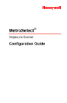
3.4.1 Metrologic ScanGlove IS4225 ................................................................................................... 24
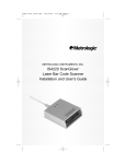
3.4.2 ROV Scanner ............................................................................................................................. 25
3.4.3 LS2208 Handheld Barcode Scanner from Symbol .................................................................... 26
3.5 Wi-Fi modules vs. Wired .................................................................................................................. 27
3.6 Universal Product Code and Price Lookup Code Databases ............................................................ 28
3.6.1 UPC grocery (upcgrocery.com) ................................................................................................. 29
3.6.2 UPC Database (upcdatabase.com) ............................................................................................. 29
3.6.3 IFPS PLU Database (plucodes.com) .......................................................................................... 29
3.7 Google Image Search API ................................................................................................................ 30
3.8 Temperature Sensors ......................................................................................................................... 30
3.9 Power source implementation ........................................................................................................... 31
3.10 Software Components ..................................................................................................................... 33
3.10.1 Mobile App & Website ............................................................................................................ 33
3.10.2 Programming Languages ......................................................................................................... 35
3.10.3 Web Development Languages and Platforms .......................................................................... 37
3.10.4 Communication Systems.......................................................................................................... 38
3.11 Database .......................................................................................................................................... 39
3.12 Previous Works ............................................................................................................................... 41
3.12.1 Existing products...................................................................................................................... 41
3.12.2 Existing Projects ...................................................................................................................... 42
4. Design ..................................................................................................................................................... 42
4.1 Rationale for Hardware Component Selection ................................................................................. 42
Wifi module Technical Specifications ................................................................................................ 43
4.2 Software Design ................................................................................................................................ 44
4.2.1 Software Structure...................................................................................................................... 44
4.1.2 Use Case Diagram...................................................................................................................... 53
4.2.3 Flow of operations ..................................................................................................................... 55
4.2.3 Class Diagrams .......................................................................................................................... 61
4.2.4 Database Structure ..................................................................................................................... 63
4.2.4 Server ......................................................................................................................................... 69
iii
4.3 Hardware Design .............................................................................................................................. 70
4.3.1 Hardware Comparison ............................................................................................................... 70
4.3.2 Hardware Component Interaction .............................................................................................. 72
4.3.3 Power ......................................................................................................................................... 73
4.5 Printed Circuit Board Design Summary ........................................................................................... 74
5. Prototype ................................................................................................................................................. 81
5.1 LCD Display ..................................................................................................................................... 81
5.1.1 Main Menu ................................................................................................................................. 81
5.1.2 Items Menu ................................................................................................................................ 82
5.1.3 Enter Items Page ........................................................................................................................ 82
5.1.4 Items List Summary ................................................................................................................... 83
5.1.5 Modify Items & Remove Items ................................................................................................. 84
5.1.6 Modify Items From List ............................................................................................................. 85
5.1.7 Edit Item..................................................................................................................................... 85
5.1.8 Remove Item .............................................................................................................................. 86
5.1.9 Remove Items from List ............................................................................................................ 87
5.1.10 Shopping List Menu ................................................................................................................. 88
5.1.11 Delete Shopping List ................................................................................................................ 89
5.1.12 Delete Shopping List Confirmation ......................................................................................... 89
5.1.13 Add Items To Shopping List .................................................................................................... 90
5.1.14 Shopping List Summary........................................................................................................... 91
5.1.15 Modify Existing Shopping List ................................................................................................ 92
5.1.16 Edit Shopping List ................................................................................................................... 93
5.1.17 Recipes Menu........................................................................................................................... 94
5.1.18 List of Recipes ......................................................................................................................... 96
5.1.19 Recipe Description ................................................................................................................... 97
5.1.20 LCD Display Settings .............................................................................................................. 99
5.2 Mobile App ..................................................................................................................................... 101
5.2.1 Main Menu ............................................................................................................................... 101
5.2.2 Items Menu .............................................................................................................................. 101
5.2.3 Shopping List Menu ................................................................................................................. 102
5.2.4 Recipe Menu ............................................................................................................................ 103
iv
5.7 Web application prototype .............................................................................................................. 105
6. Testing .................................................................................................................................................. 110
6.1 Code testing .................................................................................................................................... 110
6.2 Website/Mobile App testing ........................................................................................................... 111
6.2.1 Website testing ......................................................................................................................... 111
6.2.2 Mobile App testing................................................................................................................... 111
6.3 Database testing .............................................................................................................................. 112
6.4 Server testing .................................................................................................................................. 113
6.5 Hardware Components testing ........................................................................................................ 113
6.5.1 LCD Display testing................................................................................................................. 113
6.5.2 Scanner testing ......................................................................................................................... 114
6.5.3 Wi-Fi Module testing ............................................................................................................... 114
6.5.4 Temperature sensor testing ...................................................................................................... 114
6.6 Barcode Recognition testing ........................................................................................................... 115
7. Reflections ............................................................................................................................................ 115
7.1 Future Improvements ...................................................................................................................... 115
8. Summary ............................................................................................................................................... 117
9. User‘s Manual ....................................................................................................................................... 118
9.1 Main Application ............................................................................................................................. 118
9.2 Mobile Application .......................................................................................................................... 125
9.3 Website ........................................................................................................................................... 135
10. Appendices.......................................................................................................................................... 145
10.1 Copyright permissions .................................................................................................................. 145
10.2 Bibliography ................................................................................................................................. 153
10.3 Software ........................................................................................................................................ 156
v
Table of Figures
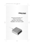
Figure 1: Hardware Components‘ Phases and division .............................................................................. 14
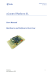
Figure 2: Software Components’ Phases and division ................................................................................ 15
Figure 3BeagleBoard Hardware architecture components. ........................................................................ 20
Figure 4 OK6410 Hardware architecture components............................................................................... 22
Figure 5 PandaBoard Architecture. ............................................................................................................. 23
Figure 6 Metrologic ScanGlove ................................................................................................................... 25
Figure 7 Microvision‘s ROV scanner. ....................................................................................................... 26
Figure 9 TiWI- R1 Module. ........................................................................................................................ 28
Figure 10 5V DC regulated supply system ................................................................................................. 31
Figure 11: First choice for power implementation ...................................................................................... 32
Figure 12: Fridge Display Breakdown ........................................................................................................ 45
Figure 13 Items Menu Breakdown.............................................................................................................. 46
Figure 14: Recipes Menu Breakdown ......................................................................................................... 47
Figure 15: Shopping List Menu Breakdown ............................................................................................... 48
Figure 16 Mobile App Breakdown ............................................................................................................. 49
Figure 17 Shopping List Menu Breakdown ................................................................................................ 50
Figure 18 Recipe Menu breakdown ............................................................................................................ 51
Figure 19 Website breakdown .................................................................................................................... 52
Figure 20 Website Shopping List breakdown ............................................................................................. 52
Figure 21 Website Recipe's Menu Breakdown ........................................................................................... 53
Figure 22 UML Use-case diagram .............................................................................................................. 54
Figure 23 Sequence Diagram for the LCD Adding New Item.................................................................... 56
Figure 24 Sequence Diagram for the LCD View Recipe ............................................................................ 56
Figure 25 Sequence Diagram for the LCD Shopping List ......................................................................... 57
Figure 26 Sequence Diagram for the Web Application Login and View Items ......................................... 57
Figure 27 Sequence Diagram for the Web Application View Shopping List ............................................. 58
Figure 28 Sequence Diagram for the Web Application Recipes ................................................................ 58
Figure 29 Sequence Diagram for the Phone Application Recipes .............................................................. 59
Figure 30 Sequence Diagram for the Phone Application Shopping List .................................................... 60
Figure 31 Sequence Diagram for the Phone Application View Item ......................................................... 61
Figure 32: LCD Display Class Diagram ..................................................................................................... 61
Figure 33: Phone Application Class Diagram............................................................................................. 63
Figure 34 Connected Relation .................................................................................................................... 65
Figure 35 Item Table ................................................................................................................................... 66
Figure 36 Contain Relation ......................................................................................................................... 67
Figure 37 Entity Relationship Diagram ...................................................................................................... 68
Figure 38 Server Structure Diagram ........................................................................................................... 70
Figure 39 Hardware Component Interaction ............................................................................................. 73
Figure 40 Schematic Capture of OMAP 3530 1st level.............................................................................. 75
Figure 51 Main Menu page ......................................................................................................................... 81
vi
Figure 52 Items Menu page ........................................................................................................................ 82
Figure 53 Enter Items page ......................................................................................................................... 83
Figure 54 Items List Summary page ........................................................................................................... 84
Figure 55 Modify Items page ...................................................................................................................... 85
Figure 56 Edit Item page............................................................................................................................. 86
Figure 57 Remove Item page ...................................................................................................................... 87
Figure 58 Remove Items from List page .................................................................................................... 87
Figure 59 Shopping List Menu page ........................................................................................................... 88
Figure 60 Delete Shopping List page .......................................................................................................... 89
Figure 61 Delete Shopping List Confirmation page ................................................................................... 90
Figure 62 Add Items to Shopping List page ............................................................................................... 91
Figure 63 Shopping List Summary page..................................................................................................... 92
Figure 64 Modify Existing Shopping List page .......................................................................................... 93
Figure 65 Edit Shopping List page ............................................................................................................. 94
Figure 66 Recipes Menu ............................................................................................................................. 95
Figure 67 Pop up window when choosing amount of missing ingredients................................................. 96
Figure 68 List of recipes ............................................................................................................................. 97
Figure 69 Optional Search Option for recipes ............................................................................................ 97
Figure 70 Recipe description ...................................................................................................................... 98
Figure 71 Adding a Recipe Ingredient to a shopping list............................................................................ 99
Figure 72 Settings Menu ........................................................................................................................... 100
Figure 73 Settings Password Change ........................................................................................................ 100
Figure 74 Main Menu screen of the phone application............................................................................. 101
Figure 75 Items Menu screen for the phone application. .......................................................................... 102
Figure 76 Shopping List Menu screen for the phone application. ............................................................ 102
Figure 77 Create New List screen for the phone application .................................................................... 103
Figure 78 Modify List screen for the phone application ........................................................................... 103
Figure 80 Recipe Menu screen for the phone application......................................................................... 104
Figure 79 Recipe Menu screen for the phone application......................................................................... 104
Figure 81 Recipe instructions screen ........................................................................................................ 105
Figure 82: Login Page Prototype .............................................................................................................. 106
Figure 83 Home Page Prototype ............................................................................................................... 106
Figure 84 View Item Prototype ................................................................................................................. 107
Figure 85 Shopping List Prototype ........................................................................................................... 108
Figure 86 View Recipe Prototype ............................................................................................................. 108
Figure 87 Create Recipe Prototype .......................................................................................................... 109
vii
Table of Tables
Table 1 Software Components Table ............................................................................................................ 5
Table 2 Hardware Components..................................................................................................................... 6
Table 3 Budget Projection ........................................................................................................................... 7
Table 4 Time-activity relation chart............................................................................................................ 13
Table 5......................................................................................................................................................... 13
Table 6 Innolux LCD Panel specification ................................................................................................... 18
Table 7 IMO Pivot Touch ........................................................................................................................... 18
Table 8 Belkin Wireless G .......................................................................................................................... 27
Table 9 Tiwi R1 Module ............................................................................................................................. 27
Table 10 SDK Comparison Table ............................................................................................................... 34
Table 11 PandaBoard Technical Specifications .......................................................................................... 43
Table 12 Use Case Diagram contents ......................................................................................................... 55
Table 13 Hardware Comparison and Price ................................................................................................ 72
1
1. Executive Summary
SMIDGE: the Smart Fridge System; an appliance that offers an enhanced grocery shopping
experience. It aims to be the kitchen appliance that every home must have, offering the user the
ability to implement smart shopping lists and recipes custom to their preference and list of
already acquired items. SMIDGE interacts with the user and allows the use of today‘s peak
technologies. From the private sector point of view, SMIDGE simplifies homes, simplifies life
and gives people back all that time that is wasted on dealing with kitchen inventories, shopping
lists and complex recipes. From the industrial point of view, the creation of a database that is
linked to several hardware and software components, from which the database can be accessed
and modified, is definitely an idea that can be used in future applications.
The team decided to engage in a smart fridge project for the technology challenge it represents
and how beneficial it can be in our everyday life. The project merges different technologies to
come up with the final result. Phone application technologies, web servers, web applications and
the hardware technology that involves connecting a fridge, printed circuit board, LCD display
and a scanner were used. There have been some attempts at creating smart fridge systems but
none have made a real breakthrough.
SMIDGE addresses all the functions that regular refrigerators have, and it adds new features that
make the system unique in its nature. Refrigerator technologies in the current market are very
similar from one competitor to the other. They all have the same basic functionality; keep items
cool and fresh with no outside or remote view of its inventory. Based on this fact, we trust that
our system fares well in the market. SMIDGE allows the user to remotely access the system. It
can be accessed anywhere with an Android-based smart-phone or any computer with internet
access. With a database that manages the items in the system, it will be able to store the recipes
and the different shopping lists that are created. The system allows for optimal user interaction
regarding items, shopping lists, and recipes. SMIDGE also handles multiuser situations for use in
the common case of two or more people living in the same household with separate item
inventories. By providing an account for each user to create, each will be able to manage its own
item shopping lists and recipes as they wish. The idea of separate accounts arose from real life
experience of the team members living with roommates and not having an effective system to
manage their grocery shopping. In such scenario, every person buys their own food and handles
their food items individually. In the case that these people share a common fridge, this becomes
problematic. With separate users accounts each person gets to keep their own inventory and
personal recipe list.
While there are several companies with smart fridge systems that have attempted to put forth
their product in the market, most never fared well. These ideas are innovative in their own
category, composed mainly of a screen placed on the refrigerator that displays television
channels and handles the refrigerator‘s temperature. There are also smart fridge systems that
attempt to create a more eco-friendly environment by reducing power and water consumption.
The SMIDGE system‘s purpose does not attempt to get into these areas, it is geared more
towards the customer experience. It simply allows the user to access valuable information
regarding their grocery items and shopping lists in all places, at all times; setting it apart from
any other product already existing in today‘s market.
2
2. Project Definition
2.1 Motivation
What can you make with two mangoes, some leftover chicken, an onion, coconut milk, lemon
juice and some spices? Questions like this were what inspired our group to create an application
that would be able to put together a delicious meal from what you have in your fridge. In
addition instead of asking this question why not let the application know what you already have
in stock at the moment of purchase or when you are running low of certain item, or if it is
completely out of stock. Imagine this and some other features added to one of the most used
appliances in any home the Refrigerator.
The motivation for ―Smidge‖ was to incorporate one of the most used appliances in the
household to the era of smart devices. The idea came up when the group made the suggestion of
a project that will make life a little bit easier for users. With ―Smidge‖ you would not have to
worry about running out of a particular item, or searching through your shelves looking for items
that you need to buy to put them on a shopping list. ―Smidge‖ is linked to your cell phone
through an Android application so you will have access to your fridge and pantry inventory
twenty four hour a day, seven days a week. Smidge database is also going to be synchronized to
a website to make it easier to replace items or make adjustment to the inventory.
As mentioned earlier Smidge eliminates the question of ―What meal can I make?‖ or ―What
ingredients do I need, in order to make this recipe?‖ Smidge has a recipe database that creates a
list of ingredients, the corresponding quantities, and step by step directions on how to make the
recipe. The user now has different categories of food on the touch screen display, from which
he/she can pick, like ―Quick and Easy‖, ―Mexican Food‖, ―Spanish food‖, ―Asian‖, and more.
Smidge prioritizes the use of nearly expired items to reduce the waste of food and money.
Since you probably have not yet answer the question asked at the beginning of this section here
is the answer that will be given by ―Smidge‖:
Q: Two mangoes, some leftover chicken, an onion, coconut milk, lemon juice and some spices?
A: Name of the recipe ―Chicken Mango‖, plus a list of all the ingredients needed the amount that
you will need from each ingredient and the directions on how to mix them all and end up with a
delicious homemade meal.
2.2 Goals and Objectives
There are several goals and objectives that were taken into account when developing the design
of this project. Many of these goals are specific to each component. The following are the
different areas for which specific goals have been laid out. All these goals are beneficial when
listing all of the specifications of the different components in the project
Cost Efficiency - While the Smidge was not being limited to a specific cost limit, one of the
main goals for the overall system development is to try to maintain the overall system cost
effective. This does not mean that any of the functional requirements will be sacrificed. For the
system to work, many parts will have to be compatible with each other. Having this in mind,
when given the option between different types of possible architecture implementations, cost
efficiency will be given priority over improved performance. If the difference is minimal
3
however, the architecture which produces higher performance will be selected. The threshold
determining whether to select performance over cost efficiency will be determined during parts
selection.
Fridge Display - The fridge display is the main interaction point between the user and the
system. Therefore, it is crucial that this display is as user friendly as possible. Everyone has
seen at some point a product which is extremely beneficial and highly functional but the
interface makes the product difficult to use. As the developers of the Smidge, our main goal in
creating the fridge display was to avoid this problem, and enhance user interaction. There are
five different areas which have to be kept in mind when enhancing usability. These include the
learning curve, efficiency, ability to memorize, errors, and satisfaction. The learning curve
measures the degree of difficulty for which the user can accomplish the desired tasks in with the
display for the first time. Once the user has learned how to perform these tasks with the display,
efficiency is measured on how quickly these tasks can be performed. Memory is established
how well the user remembers to use the display. That is, after not seeing the system for a long
period of time, how long does it take the user to regain proficiency in completing the desired
tasks. The last two steps are errors and satisfaction. The user is always expected to commit
some errors when using the system. Improving the errors phase consists of reducing the number
and severity of errors, and increasing the recovery from these errors. Satisfaction measures how
much the user enjoys using the design. All these steps were taken into account when developing
the fridge display. Now, the user should feel extremely comfortable interacting with this system.
Web Interface - The web interface inherited the same goals of the fridge display and tackled on
additional goals. Since the web interface was not restricted development under a language that is
optimal for the hardware as is the case with the fridge display, there were several aspects that
could be optimized by researching different modes of implementation. The web interface must
still be user friendly. One of the additional goals within developing the web interface is
increased aesthetics. The web interface is not limited in display size as are the fridge display and
the mobile app interface. That leaves plenty of room for enhancing the graphical user interface
in ways that are only possible in this platform. In essence, the web interface will be the superior
interface of the three. Since it is not mobile or attached to the main device, the web interface
must have some attributes for which the user can feel compelled to use it. This can be achieved
by providing as much information to the user on the screen as possible.
Mobile App Interface - The mobile app interface will inherit the same goals mentioned for the
fridge display. Additionally, one of the main goals of the mobile app is to make up for a small
display size by providing the most useful information to the user while not near the device. In
other words, only the basic and necessary information will be available on the mobile app
interface. This might include a quick list of items in the fridge, shopping list and items of that
nature. Another goal that is associated with the mobile app interface is continuity. Most mobile
apps follow a design workflow that allows the application to be easily used from a mobile
device. By following some of the mobile app standards the user will be able to use the mobile
app with a very small learning curve.
Shopping List - Our main goal in creating the shopping list feature is to provide the user with
the most useful information regarding groceries. Having data stored in our database regarding
these items that the user buys allows the system to display this information when needed. The
system can let the user know what items are currently on the fridge. Furthermore, the system
4
should provide a way for the user to determine what items that are usually in the fridge are
missing. One goal in producing a useful shopping list feature is to have information be exclusive
to the current user using the device. That is, if several different people use the smidge, then the
functionalities of the shopping list should reflect the information for that specific user. The
detail of the information provided also needs to be a priority in developing this feature. The
more information the user can get regarding each item the better. Such information could
include price, image, amount, and places containing the item depending on the availability of
that information to the system.
Recipe - The recipe is currently being looked at as a possible add-on to the Smidge. Having the
information of what grocery items are already in the fridge, the goal of this functionality would
be to provide the user with the recipes that are available to the user with the items in the fridge.
Another goal of this recipe functionality would be to display recipes either created by the user or
gathered from other database, that way allowing the user to view the recipes in its collection
regardless of what items are currently in the fridge.
Bar Code Scanner - Adding a bar code scanner to the Smidge allows the system to attain and
organize data regarding the grocery items. This is a crucial component of the project since it
enhances the interaction between the user and the device. With the barcode in place the user
does not have to enter specific information regarding each item. That would take a long time and
the user would be hesitant to use the device frequently. The barcode allows the system to pull up
all of the data needed by referencing the barcode value given by the scanner. The goals related
to the scanner involve reliability, efficient, small in size, and cost efficient. The scanner must be
reliable since it is placed in the Smidge for an every-day use. Efficiency plays a big role in
making the Smidge user friendly. Should the scanner be slow and not responsive, the user would
get frustrated when placing items inside the fridge. As mentioned, a third goal is to have a
device that is small enough. This will aid in the mounting phase of the project. Although
performance will be prioritized when selecting a scanner, our goal still remains to develop a
finished product that is cost efficient.
Wireless Communication - One of the main goals in developing the project is to avoid wired
connections to gain online access. If the server used to store the database is not hosted locally
and an outside service is used to store the data, our goal is to be able to connect to it through the
implementation of a Wi-Fi module. This follows that the board that is chosen should be able the
developers to integrate a Wi-Fi module that is efficient and cost effective as specified in the
previous section.
Power Implementation - Reducing the amount of time the hardware is developed requires
simplification on the way the power source is developed. Many devices in the project could
have their own power source requirements. Ideally, the user should only have to provide power
to the main device and the rest of the components on this device would be powered. As
consistent with the rest of the project, simplicity is our main goal regarding this area. If time
allows, the power source implementation should be simplified to one main source for the entire
device.
Database System - There are several goals that are always present when designing a database.
Things that usually should be kept in mind during the design of a database include easiness of
information retrieval, usefulness of information, and organization. Reducing redundancy and
5
excluding inconsistencies is also very important. There are three main goals, however, that we
have for our database development. We want the database design to be logically correct and
complete, to retain relational integrity and retain data integrity. For a database to be logically
correct and complete, the capture and maintenance of the data must be accurate and plentiful
enough to solve the problem at hand. The second goal means that the relations between tables
must be correctly linked with primary keys. The third goal pertains to the security of the
database. This follows that each table will only allow data that is of the correct type for each
field.
2.3 Scope of Work
Refrigerators are appliances developed for food freshness and storage. Due to this era of
technology innovations and ―smart items‖, new functions should be developed in order to satisfy
consumer demands. Based on recent market studies, our team decided to build ―Smidge‖, the
first Smart Fridge System.
2.3.1 Objectives
Smidge, with its innovative technology, turns a regular refrigerator into a new level of customer
convenience. It is designed to satisfy customers‘ needs. Smidge is a refrigerator system that will
keep an inventory of the items inside the fridge, give feedback on nutrition and health, and
provide a weekly grocery list. Smidge will have a small display monitor on which you can check
the inventory in your refrigerator. It has a mobile application that will run on Android phones,
allowing the user to manage the content of their fridge and have access to their shopping lists and
recipe creation. Smidge will have a bar code scanner that will be used to enter the items into the
fridge electronic inventory. Every food item will be scanned before being entered into the
fridge. Once the user has chosen to add the item to the list, the information will be stored in the
inventory. When new items are scanned, and not found in the database, the user will have to
manually enter the information regarding the product, then Smidge will save the new information
in the database and have it for future reference. There is a main database that will be stored
remotely using a Google App Engine web application that will act as the main server. From here,
we are able to retrieve information to use in the fridge system, website and mobile application
2.3.2 Tasks
The table below shows all the Software Components that shall be part of the project and the
group member in charge of it.
Tasks
Member Group Responsible
Server Configuration
Felipe Bernal
Database Structure
Felipe Bernal
Data Processing
Arian Caraballo
Display GUI
Isabel Virag
Display Programming
Isabel Virag
Mobile Apps+ Alerts
Daniela Zicavo
Table 1 Software Components Table
6
The table below shows all the Hardware Components that shall be part of the project and the
group member in charge of it.
Tasks
PCB
Display
Mounting
Power
Member Group Responsible
Felipe Bernal & Isabel Virag
Isabel Virag
Arian Caraballo
Daniela Zicavo
Table 2 Hardware Components
2.3.3 Schedule
The project shall take 4 months to be implemented, the duration of a school semester. We shall
start on January 2011 and it should be completed by April 2011.
2.4 Significance
This project represents a jump in technology, adding another appliance to the so call ―smart era‖.
From a social point of view our project simplifies the everyday life of its users. Cooking, making
shopping lists and taking care of provide our kitchen cabinets may seem a very easy thing to do
and in fact it is, what is not easy is to find the time in our very busy lives to do this. This is one
of the major reasons why smart phones and smart technology in general have been such a
success in today‘s world, they make our lives easier, they help us make better use of our time so
we can keep doing all those little things that make our everyday life. With this idea on mind we
decided to create this project, the Smart Fridge.
There are several functions that our team was not able to implement in our project. It was our
desire and hope that these ideas shall be put in practice in future versions of our project. These
functions made the project of ―green-implementation‖ nature. The new functions are related to
the use of energy and power of SMIDGE. Future SMIDGE projects shall be able to regulate the
fridges inside temperature in order to have less power consumption. With ideas like the prior one
implemented into SMIDGE the fridge shall require low energy to work, which compare to the
rest of refrigerators on the market will be a big difference.
From the technology point of view this project gave us the opportunity of integrating several
hardware components all in one final task. After a lot of research and hours in the lab we ended
up with a system that worked as a whole, integrating a refrigerator, a board, a scanner, a display
and a cell phone. It sounds a little crazy to be able of putting all this items together but that is our
goal. For our team and each of its integrants personally this project shall be the biggest learning
experience of our lives as students.
2.5 Budget projection and financing
The entire project was financed by the group members. We split the cost equally between the
four of us. We expected to spend at least seven hundred dollars and no more than one thousand
US dollars on our project.
7
Item
Quantity
PandaBoard
1
IMO pivot touch
1
HONEYWELL IS4225 SCANGLOVE
1
Refrigerator
1
PCB
2
Power management
1
Website with Google App Engine
1
Wi-Fi Module
1
Custom Board
1
USB Hub
1
5V power supply
1
Total
Table 3 Budget
Cost (in dollars)
175
170
35
0 – owned by member
400
20
0
0
160
20
20
800
2.6 Specifications
2.6.1 Overall Specifications
The system shall have three main components: the physical system placed on the refrigerator
with a development board, an LCD display, a user interface, and a barcode scanner; a mobile
application that will allow the user to check their inventory on the go; and a website to
accommodate for a simpler and faster user interaction. The physical touch interface will have
access to the information posted on the website and mobile application through a remote server
and vice versa.
The physical system shall be placed securely on the refrigerator.
The system shall be comprised of an LCD touchscreen, a development board with
Android Operating System and wifi capabilities; and a Barcode scanner.
The LCD touchscreen shall be placed on top of a small refrigerator or on the front a
regular-sized refrigerator.
The barcode scanner shall be placed on the side of the refrigerator such that there is no
interference when the refrigerator door is open, for an easy scanning process.
The system shall be powered by the same source cable that powers the refrigerator.
The system shall be powered by no more than 5 volts through a regulator.
The system shall have wifi capabilities to connect through the user‘s network.
The system shall be able to synchronize periodically with the remote server, and
consequently handle the same inventory information available through the mobile
application and website.
The system shall have a similar interface on each one of the three segments: Refrigerator
system, mobile application and website.
The development board shall carry the Android Operating System that will drive the
touch interface as well as the mobile application.
The web interface shall be developed using Google App Engine which will allow for a
simple user interface and ease of use.
8
All hardware components shall be connected together in a compact manner around the
refrigerator.
2.6.2 Barcode Scanner
The Barcode Scanner is in charge of reading the Universal Product Code located in any one of
the products that will be placed inside the fridge, and delivering it as a sequence of numbers in
the form of a keyboard input. This keyboard input will then be entered into a search for product
recognition. The scanning system is responsible for linking this input read in by the scanner to
the inventory API. The information is then retrieved and displayed in the LCD on the refrigerator
system.
The system shall be able to scan a Universal Product Code (UPC) from the products that
provide one.
The system shall translate barcodes from the reader into numbers.
The system shall keep an updated list of barcodes with products they correspond to in an
inventory stored in the local database.
The Inventory API shall be able to read/write from the local database to keep track of the
inventory items.
The system shall frequently update the local database with the database on the remote
server hosted on Google App Engine so that the webpage, mobile application and
refrigerator system all have a synchronized inventory.
The system shall use the inventory APIs incorporated into the software to find a matching
product.
The system shall be able to access the inventory API in order to locate the right product.
The system shall be able to determine if an item is present in the database.
The system shall be able to create a new item with user preferences in the database if it is
not already present.
2.6.3 Touch Interface
The touch Interface is provided through an LCD touch screen placed on top of the small
refrigerator for convenient access. With this, the user is able to easily enter and delete products
from the inventory on the system. Through this system, the user will have the option to enter a
product or a batch of products; remove a product from the inventory; change the size or weight
of the product as it progresses through its use; add expiration dates if desired with the option to
notify the user when the expiration date is reached; add and modify shopping lists and finally,
view any recipes already in the system.
The system shall be comprised of a touch screen for interaction with the user.
The system shall have a login/activation screen for the user to input their account
information they used on the website.
The system shall have a list of options available at all times for the user to choose from.
The system shall display a description of the current step on the screen for the user to be
able to understand the application with ease.
The system shall have four options for user interaction: Items, Recipes, Shopping Lists
and Settings.
9
The system shall have three main ‗item‘ options for user interaction: Add Item, Modify
Item, and Remove Item.
When pressed, the Add Item option shall allow the user to scan any amount of products
he desires, making it easy to enter one product, or a batch of products.
The system shall provide the ability to enter the description of a product, if not found on
the API database, and store it in the local database for later retrieval.
The system shall provide the ability to enter a product‘s expiration date based on the type
of product and user preference.
The system shall provide the ability to look at the current list inventory whenever the user
is done adding, modifying or deleting items.
The system shall provide the ability to modify the weight or amount of an item that is
already in the inventory.
The system shall provide the ability to remove an item or a set of items from the
inventory.
The system shall provide the ability to access shopping lists and be able to modify, add or
remove items to the lists.
The system shall provide the ability to access the recipes stored, the recipes that are
available according to what is currently stored on the inventory, and be able to retrieve
the list of ingredients needed for any of them.
The system shall provide the ability to change or view settings in the user‘s account and
preferences.
2.6.4 Web Interface
The Web Interface resembles the touch interface very closely. It is responsible for offering yet
another option for the user to check their current fridge inventory and make any changes; as well
as create shopping lists, adjust shopping lists, create or delete recipes. The webpage plays a big
part in the enhancement of user experience with the system and requires a personalized login
account for complete privacy.
The system shall provide access via a website.
The system shall request the user to create an account in order to link the information
used on the refrigerator system.
The system shall provide access to a personalized account.
The personal account shall be acquired by the user by providing an email and password.
The system shall be divided into three sections: inventory, shopping lists and recipes.
The system shall provide the ability to access the current fridge inventory.
The system shall provide the ability to create shopping lists based on the current
inventory and products bought in the past.
The system shall provide the ability to add grocery items to a list.
The system shall have a list of items that are and have been in the inventory in the past
used for examination and adding items to the shopping list.
The system shall provide the ability to modify the name and contents of a shopping list.
The system shall provide the ability to add notifications for product expiration, products
you are running out of, and when the refrigerator is reaching an undesirable temperature,
through mobile app or email.
10
The system shall provide the ability to modify the quantity, expiration date and
notifications for a specific item on the inventory list.
The system shall provide the ability to see shopping lists created in the past.
The system shall provide the ability to delete shopping lists.
The system shall provide the ability to access list of recipes.
The system shall be able to provide the user with a form to fill out for recipe information.
The system shall provide the ability to add customized recipes.
The system shall be able to process the information keyed by the user to create a recipe.
The system shall provide the ability to create new recipes with the items provided on both
the current inventory and items used in the past.
The system shall provide the ability to modify or delete customized recipes.
The system shall provide a list of grocery items needed upon request, as a shopping list,
using the list of items bought in the past to check which items are missing on the current
inventory.
The system shall provide a list of recipes on which all required ingredients are available.
The system shall provide a list of recipes containing a specific ingredient or group of
ingredients available on the inventory.
2.6.5 Mobile Application
The Mobile Application provides one of the main advantages of the system, being able to access
the inventory at any time, any place. Having the ability to access, create, and modify shopping
lists while at the grocery store makes all the hard work of keeping track of groceries worthwhile.
The contents of the mobile application are very similar to those of the website. Through the
mobile application, the user is also able to access, modify and create new recipes on the go as
well as modify items on the current inventory available.
The system shall provide access via a phone carrying the Android Operating System.
The system shall have a login/activation screen for the user to input their account
information they used on the website.
The system shall be divided into three sections: inventory, shopping lists and recipes.
The system shall provide the ability to access the current fridge inventory.
The system shall provide the ability to create an automatic shopping list based on the
current inventory and products bought in the past.
The system shall provide the ability to add grocery items to a list.
The system shall provide the ability to modify or delete the name and contents of a
shopping list.
The system shall provide the ability to add notifications for product expiration, products
you are running out of, and when the refrigerator is reaching an undesirable temperature,
through mobile app or email.
The system shall provide the ability to modify the quantity, expiration date and
notifications for a specific item on the inventory list.
The system shall provide the ability to access list of recipes.
The system shall provide the ability to add customized recipes.
The system shall provide the ability to create new recipes with the items provided on both
the current inventory and items used in the past.
11
The system shall provide the ability to modify or delete customized recipes.
The system shall provide a list of recipes on which all required ingredients are available
for use.
The system shall be able to provide the user with a form to fill out for recipe information.
The system shall be able to identify the ingredients of a recipe as products in the
inventory or check them as unavailable.
The system shall be able to build lists of recipes available for use depending on the
current items available on the inventory.
The system shall allow the modification of description of products on the inventory.
The system shall allow the modification of expiration date or size of an item on the
inventory.
2.6.6 Shopping Lists
Shopping Lists are created by the user in order to have a list of items desired to be purchased in
the future. They are available for creation, viewing, modification and deletion through the three
interfaces: mobile application, refrigerator system and website. The user should be able to add
his personal shopping lists with different names. Also, there should be a shopping list
automatically created by the system that provides an up-to-date list of items the system has
analyzed and concluded the user shall need. This list will be based on items bought in the past,
items the user has already disposed of, or items whose expiration date is approaching. Based on
user preferences, the shopping lists will have the ability to get sent through email or mobile
application notifications.
The system shall provide the ability to create one or several shopping lists through the
mobile application, refrigerator application, and website.
The system shall allow the user to modify available shopping lists.
The system shall allow the user to delete shopping lists created in the past.
The system shall create an automatic shopping list based on products that have been
purchased before, and the products currently available on the inventory.
The system shall be able to update the automatic shopping list periodically with the
current inventory.
The system shall be able to synchronize shopping lists to be used within the refrigerator
system, mobile application and website.
The items in a shopping list shall be automatically crossed out from a list whenever the
user scans the item into the refrigerator after purchase.
The system shall be able to perform a Universal Product Code search on the API to look
for items that have never been purchased before to add to the shopping lists.
2.6.7 Recipe Creation
Recipes will be comprised of a list of ingredients and an itemized procedure divided into steps.
The user will have to input these recipes into the system through the mobile application or
website; however, the recipes should be viewable through all interfaces, including the
refrigerator system. The system should be able to determine which recipes are available for
creation based on the items currently available on the inventory. It should also be able to
determine which items are missing in the inventory from a selected recipe.
12
The system shall provide a database for holding recipes, their ingredients and itemized
procedures.
The system shall provide the ability to create recipes through the website interface or
mobile application.
The system shall provide access to a list of ingredients of a chosen recipe when
requested on the refrigerator system.
The system shall provide the ability to modify recipes amount, ingredients and
procedures.
The system shall provide the ability to delete recipes.
The system shall provide a list of all recipes in the database when requested by the user
interaction with the interface.
Upon request, the system shall provide a list of recipes for which all items with their
corresponding amounts are available on the current inventory.
The system shall be able to synchronize recipes to be used within the refrigerator system,
mobile application and website.
The system shall let the user decide on the refrigerator system, whether to show the
entire procedure for a recipe, or just the ingredients.
The system shall be able to perform a Universal Product Code search on the API to look
for items that have never been purchased before to add to the custom recipes.
2.6.8 Notification System
The notification system will be implemented to alert the user about items soon to reach their
expiration date, items soon to be discarded, undesirable temperature readings, or shopping lists
selected through user preferences. It can be implemented to use email or mobile application
notifications in a mobile phone.
The system shall be able to create a notification at the time specified by the user on the
system preferences.
The system shall be able to check when items are about to be expired at a time set by the
user each day and create the necessary notification.
The system shall be able to monitor the temperature readings for when they fall too low
or rise too high.
The system shall be able to check when a user is running low on an item at a time set by
the user each day and create the necessary notification.
The system shall be able to create a notification through email or mobile application
notification according on user preferences.
The user shall be able to set the preferences for the notification system through their
mobile application or the website.
2.6.9 Temperature Sensor
Temperature sensors will be used simply to display the internal temperature of the refrigerator on
the LCD panel at all times. It will serve the purpose of letting the user assess if the temperature
reading is either too high or too low for the food that is in the refrigerator.
13
The system shall be located inside the refrigerator, at a spot where the temperature
readings are examined to be consistent and reliable.
The system shall provide temperature readings from the location of the sensor.
The system shall have a threshold of high and low limits set by the user.
The system shall provide alerts when temperatures fall below or above the threshold.
2.7 Milestone Gantt chart
The chart on Table 4 is a time and activity bar chart that displays the project schedule in task
sequence and by the task start and finish dates. Every activity that corresponds to the project‘s
critical path, longest estimated time the project should take to be completed, is present in the left
side of the chart under the column name Task Name. The chart shows the time duration for each
activity as a horizontal blue axis for the activities corresponding to the first phase or Senior
Design I and red for the ones corresponding to the second phase or Senior Design II. All the
activities are list down and the top bar corresponding to Smart Fridge represents the total activity
period between both phases. The lines connecting bars represent dependencies between
activities. There are tasks that can only start after another task was completed.
Sep 2010
ID
Task Name
Start
Finish
Oct 2010
Nov 2010
9/12
9/19
9/26
10/3 10/10 10/17 10/24 10/31 11/7 11/14 11/21 11/28 12/5 12/12 12/19 12/26
1
SmartFridge
9/13/2010
4/26/2011
32w 2d
2
Concept and Definition
9/16/2010
9/20/2010
5d
Felipe, Daniela, Isabel, Arian
3
Definition Document
9/22/2010
9/22/2010
1d
Felipe, Daniela, Isabel, Arian
4
Hardware Research
9/27/2010
10/8/2010
1w 5d
5
LCD Touch screen displays
9/27/2010
10/1/2010
5d
Arian
6
Boards
9/27/2010
10/1/2010
5d
Isabel
7
Scanners
9/27/2010
10/1/2010
5d
Isabel
8
Power
9/27/2010
10/1/2010
5d
Daniela
9
Temperature Sensor
10/4/2010
10/8/2010
5d
Felipe
10
WiFi
10/4/2010
10/8/2010
5d
Arian
11
Software Reseach
10/9/2010 10/21/2010
Dec 2010
Jan 2011
Feb 2011
Mar 2011
Apr 2011
Duration
1/2
1/9
1/16
1/23
1/30
2/6
2/13
2/20
2/27
3/6
3/13
3/20
3/27
10/15/2010
1w
Isabel
13
Android SKD
10/9/2010
10/15/2010
1w
Felipe
14
Windows Mobile SKD
10/9/2010
10/15/2010
1w
Felipe
15
Programing Language
10/9/2010
10/15/2010
1w
Isabel
16
Website
10/16/2010 10/21/2010
6d
Felipe
17
Database
10/16/2010 10/21/2010
6d
Daniela
18
Hardware Design
10/22/2010
11/1/2010
1w 4d
19
Software Design
10/22/2010
11/1/2010
1w 4d
20
Order Parts
10/17/2010
1/15/2011
13w
21
Preparatory Project Document
10/9/2010
12/2/2010
7w 6d
22
Final Project Document
12/3/2010
12/6/2010
4d
23
Prototype
1/10/2011
4/2/2011
11w 6d
Isabel, Felipe
Arian, Daniela
Isabel
Felipe, Daniela, Isabel, Arian
Felipe, Daniela, Isabel, Arian
24
Phone App
1/10/2011
3/10/2011
8w 4d
Daniela
25
Website
1/10/2011
3/10/2011
8w 4d
Arian
26
Database
1/10/2011
3/10/2011
8w 4d
Daniela
27
LCD
1/10/2011
3/10/2011
8w 4d
28
Assemble Parts
3/11/2011
3/13/2011
3d
Code
4/24 5/1
1w 6d
10/9/2010
Test
4/17
Senior Design I
UPC Online Database
30
4/10
Senior Design II
12
29
4/3
3/14/2011
4/2/2011
2w 6d
2/26/2011
4/20/2011
7w 5d
Felipe
Felipe, Daniela, Isabel, Arian
Isabel
31
Phone App
2/26/2011
4/15/2011
7w
32
Website
2/26/2011
4/15/2011
7w
Arian
33
Databse
2/26/2011
4/15/2011
7w
Daniela
34
LCD
2/26/2011
4/15/2011
7w
Felipe
35
Code
4/3/2011
4/20/2011
2w 4d
4/26/2011
4/26/2011
1d
36
Demostration
Daniela
Isabel
Table 4 Time-activity relation chart
Table 5
14
3. Research
3.1 Implementation Methodology
3.1.1 Project Management
Managing a project can be very troublesome and problematic if not done correctly. We feel that
it was critical for the team to research this topic in order to organize the project in appropriate
phases and steps. The foremost challenge of project management is to accomplish all of the
engineering project goals and objectives. These goals have been defined in the Project
Definition and are explicitly stated. These goals and objectives have to be met while keeping in
mind the predetermined project constraints. These usually include scope of work, time, and
budget.
Some approaches to project management put an emphasis on the head of the group. That is, the
project manager is the vital component for a project to successfully run its course. Others
however, describe a more structured, systematic way of managing projects. All of the members
in the group have engaged in projects of different scales both job-related and academic.
Figure 1: Hardware Components’ Phases and division
We believe that to improve the dynamics of our team, we should refrain from selecting a project
manager. Instead, we will use a well structured plan and ensure the team has a high level of
communication to achieve all of the project goals.
15
Each member of the group has specialized knowledge in different technologies. The project will
be broken down to different components and each member will be responsible for its assigned
area. This does not mean that this person alone will develop this part of the project. Instead, this
team member will in essence be the leader for that specific task. The tasks will be assigned
according to the level of knowledge in that specific subject. The hardware related components
can be seen on the diagram in Figure 1 while the software related components can be seen on the
diagram in Figure 2.
Figure 2: Software Components’ Phases and division
To carry out the project in an organized and structured way, a common approach to managing
projects will be implemented. This methodology contains the following phases: Analysis,
Design, Build, Test, and Rollout. This methodology has been used by some of the team
members in various projects both academic and non-academic. It is a system that has been
proven to work and has allowed the members of the team that are working on the project to
effectively make use of their time. No phase is more important than another as each of them is
crucial to the success of the project. Some tasks from different phases can be parallelised and
some tasks in different phases can be ongoing throughout the project. Such tasks include
research of different technologies as the project progresses. In the analysis phase, the problem is
discussed. This phase consists of describing all of the possible implementations, possible
16
challenges, and so on. The design phase provides the conceptual design of the project and then
the architectural design is defined. During the build phase, the team will use the design
specifications developed to come up with a prototype. The test phase consists of thorough
inspection of the system and testing according to the testing specifications described in this
document. During the final phase, the rollout is performed. All required demos and
presentations are given. Project functionality approval is attained during this phase.
3.1.2 Research Methodology
The team conducted a thorough research in all of the areas involved in the development of the
project. The emphasis of the research was made on the hardware components since all of the
team members are more software oriented. This procedure was broken down into several
different components including LCD displays, development boards, barcode scanners,
temperature sensors, and Wi-Fi modules. Although it was critical to gain useful information
regarding all of the hardware parts, the software components of the project were not overlooked;
an in depth analysis of possible software components was also researched. This included
research in the fields of mobile app and web server applications, programming languages, web
development languages, and communication systems. We felt it was crucial to have all of the
required information and possible implementation options before any of the design was mapped
out.
To improve the dynamic of the research stage, the topics were split evenly within each group
member. Topics were assigned based on knowledge of the subject and also based on interest.
Most of the information gathered was retrieved from websites or emails. After reviewing all the
information gathered and comparing different product specifications, it was easier to make a
decision on what products would work best for our desired functionality. This was especially
true when comparing the development boards side to side.
3.1.3 Design Methodology
This phase of the project required numerous meetings to develop the design of all of the
components of the project. Each member‘s specific skill set was used to our advantage in
leading the discussion of the design. The database structure, for example, was put together
mostly by one of the members with previous experience with database systems, while the other
members aided in brainstorming the different fields that would be necessary for the system to
work properly. The design of the software was mostly done in stages. It was clear to the group
from the research phase, that we would implement the interface in three different platforms. The
design phase required us to create a design for the LCD display, a design for the website, and a
design for the mobile app. Each of these was designed in different stages with the group meeting
a couple of times. Most of the design efforts with these displays came from the workflow of the
programs. That is, how were the programs going to interact with the user and what type of
information would be available to the user in each platform. Numerous diagrams that pertain to
software engineering were developed to aid the visualization of the software design for this
project.
When developing a software product, it is often the case that the people developing might want
to jump straight into developing the code for that product. After undergoing the design phase, it
is clearer now that this step will facilitate and hopefully expedite the development process.
17
Team meetings were a huge aid in allowing each team member to provide their individual ideas
and brainstorm together. Many ideas that will be implemented on the project could not have
been possible if this phase would not have been performed correctly. The design methodology
used should be kept in mind for future projects, in this or any other scope.
3.2 LCD Displays
Smidge will be equipped with an LCD touch screen display. Through the display the user will
have some kind of tabbed interface from which he or she will have access to different options.
One of the main reasons for the use of a touch screen is to make the user interact directly with
what is on the screen, without having to rely on the use of a mouse or a keyboard. Second reason
is that the interaction does not require the use of any intermediate device held in the hand. A
third reason will be the likeability of this type of technology in the public. Now a day a touch
screen display can be found almost in any application, from cell phones to ATM machines.
Smidge will be equipped with an LCD touch screen display and after doing some research we
narrow our search to two choices, the ‗Innolux TFT LCD with touch panel‘ attached, and the
‗IMO Pivot Touch‘. They are both 7 inches in size, which is a relatively good size for our
purpose, and they are both touch screen displays, which adds an element of speed and ease to the
user experience when using the system.
3.2.1 Innolux TFT LCD with touch panel
This LCD panel shown in Figure 3 can be used with the OK6410 packet board. The drivers for
this board are included with the system. The main advantage of this LCD panel is that it is the
most affordable touch screen display in the market. Having the drivers readily available for use
with Android is very important and saves us a lot of time when trying to create an interaction
between all of our hardware and software components. The main issue with this screen is that
there is little support offered online. There is not much evidence that this screen has been used
before in these types of projects. The only help we could get is through emailing the
manufacturer directly. The specifications for this model are shown on Table 5.
Item
Model
Driver element
Resolution
Display model
Dot pitch
Active area
Module size
Surface treatment
Color arrangement
Contrast ratio
Interface
Current consumption
Specification
AT070TN83
a-Si TFT active matrix
800 X 480 (RBG)
Normally white, Transmissive
0.0635 (W) X 0.1905 (H) mm
152.4 (W)X91.44 (H) mm
165 (W) X 104 (H) X 5.5 (D) mm
Anti-Glare
RGB-stripe
500 : 1
Digital(TTL)
500 mA
18
Power voltage
Backlight power consumption
Panel power consumption
Weight
Operation temp.
5V
2.500W (including the T-con Board power consumption)
0.825W (including LED Driver power consumption)
130g (Typ.)
-20℃ ~ +70℃
Table 6 Innolux LCD Panel specification
3.2.2 IMO Pivot Touch
This LCD display is compatible with the PandaBoard or the BeagleBoard. It has generic drivers
which might be a little harder to configure, but on the other hand it offers community support
like forums IRC and many more. This LCD has a stand with a ball-and-joint system that offers
full 360 degrees maneuverability for optimum view. The stand can be easily detached and used
with a simple flip-out kick stand.
The main benefit of using this touch screen is that it has been proven to work with a variety of
boards, making it somewhat easier to find a way to interface this lcd display with our own
custom board. The price is not as accessible as the Innolux screen; however, there is more
support and information found on the web for this model. This model‘s specifications are shown
on Table 6. It is seven inches in size and it is also transmissive in type. The fact that it offers two
different stand types to place the touch screen adds to its beauty; and the fact that it can be
powered through USB cables makes it all the worthwhile as it can all be connected directly to
our main board.
Item
Specification
LCD size
7.0 inch (Diagonal)
Resolution
800 X 480 (RBG)
Module size
190 (W) X 133.35 (H) X 12.7 (D) mm
Contrast ratio
400 : 1
Current consumption 100-240 V
Power voltage
24 V
Weight
544.31 g (with stand)
Table 7 IMO Pivot Touch
3.3 Development Boards
The main frame of the project will be based on a development board that can handle the
operating system we choose to install and operate to create our smart fridge system. By looking
at different options, we will be able to better assess our needs based on the level of performance,
price, operating systems and availability of peripherals for each of the boards considered.
We started by looking at boards that would be able to port the Android System, as it is the
operating system we are most interested in learning; however, each one of the boards we
analyzed have other options when it comes to operating systems. Our second most important
19
condition was to have the best price-performance ratio, and we came up with three very
competitive boards to consider.
3.3.1 BeagleBoard
The first development board we are taking into consideration is the BeagleBoard. It is an
OMAP3530 platform based board that caters to the open source community. It is priced at $149
and comes with U-Boot and X-Loader software flashed onto it but no peripherals or connection
cables. However, it satisfies our need of being able to host the Android operating system at a
reasonable level of performance, price and with plenty of room for development and expansion.
It is also very popular, and plenty of information and help is provided in online forums, which
translates as a big advantage when developing our senior design project.
The BeagleBoard is 3 by 3.1 inches in size. It uses the OMAP3530 DCBB72 720Mhz version
processor that features over 1,200 Dhrystone MIPS using the superscalar ARM Cortex-A8 with
highly accurate branch prediction and 256KB L2 cache running at up to 600MHz. It comes in a
.4mm pitch pop package. POP is a technique where the memory, NAND and SDRAM are
mounted on top of the processor. The memory used on the board is a Micron POP memory
which has 2Gb NAND x 16 (256Mb) and 2Gb MDDR SDRAM. It is possible to add additional
memory to the Beagleboard if needed by adding either an SD card, MMC or through the USB
port. It offers OpenGL ES 2.0 2D/3D graphics accelerator capable of rendering 10 million
polygons per second.
The BeagleBoard has a TPS65950 power module developed by Texas Instruments to provide
power to the BeagleBoard; the 3.3V regulator in it is used to provide power to the DVI-D
encoder and RS232 driver; and it also provides stereo audio out, stereo audio in, power on reset
and power to the USB OTG port. This USB OTG port can be used as the primary source of
power and communication for the board if connected to a computer USB port; therefore the
Beagleboard requires a single minAB to USB A cable; a Y-Cable; or a 5V DC supply can also be
used.
The board provides a single HS USB 2.0 Host Port, a Stereo Audio Output connector, a Stereo
Audio Input connector, an S-Video output connection and a DVI-D connector. The USB Host
port is provided via a USB Type A connector that provides power control on/off to the system.
The 3.5mm standard Stereo Audio Output audio jack is used to access the stereo output of the
onboard audio CODEC provided by the TPS65950. The Stereo Audio-In Connector is interfaced
in the same manner. A 4 pin DIN connector is provided to access the S-Video Output that
supports NTSC or PAL format to a standard TV. And finally, a DVI-D connector that has the
ability drive an LCD panel equipped with a DVID-D digital input.
The BeagleBoard supports 24b color output, and it has a DDC2B (Display Data Channel) or
EDID (Enhanced Display ID) support over 12C in order to identify the LCD monitor type and
settings. The board comes with a DVI-D interface that uses an HDMI connector, which the user
is able to implement by using an HDMI to DVI-D cable or adapter for the LCD monitor. A pair
of 1.27mm pitch headers is provided to gain access to the LCD signals.
20
An SD/MMC 6 in 1 connector is available as a way to expand memory. It supports WiFi cards,
cameras, Bluetooth cards, GPS modules, SD Memory Cards, MMC Memory Card, SDIO Cards,
MMCMobile Cards, RS-MMC Cards and miniSD Cards.
Figure 3BeagleBoard Hardware architecture components.
Reprinted from BeagleBoard.org, licensed under a Creative Commons Attribution-Share Alike 3.0 license.
There is a reset button on the board, a User/Boot button and four LEDs on the board. The
User/Boot button does one of two things: forces a change in the boot sequence of the processor,
or is used as an application button for an implementation of the software used. It can also be used
in combination with the reset button to cause changes in the order in which boot sources are
checks as viable boot sources. There are three green LEDs on the BeagleBoard that are
controlled by the user. One is controlled via the I2C interface while the other two are processor
controlled via GPIO pins. The fourth LED indicates whether the board is on or off.
Finally, it provides a JTAG connector, an RS232 Header and an Expansion Header. The 14 pin
JTAG header facilitates the software development and debugging of the boards by using JTAG
emulators (Only 1.8V levels are supported). The RS232 Header is supported via UART3 by a
pin header on the BeagleBoard. To access the port, you need an IDC to DB9 flat cable. The
expansion header is a single 28 pin header provided to allow for the connection of expansion
cards that could be developed by the user. All of the hardware components described are shown
in Figure 4.
3.3.2 OK6410 package
Our second most comprehensive choice is the OK6410 package. It is a Single Board Computer
based on the 667Mhz Samsung S3C6410 (ARM11) microcontroller. This board has plenty of
built-in resources and powerful video processing capacity. It is priced at $110 and comes with
Board Support Packages for Linux, Windows CE and Android, including some basic drivers for
peripherals. As a package, it comes with the board, 1 serial port cable, 1 USB cable, 1 Ethernet
cable, 1 JTAG wiggler with a JTAG cable, a 5V power supply and a DVD with help information.
21
This board clearly offers more than the BeagleBoard when it comes to hardware supplies and
help provided with the system. However, it is not as popular in the open source community;
which ultimately means there isn‘t as much help out there if we get stuck solving a problem
when developing our project.
The OK6410 development board is split into two parts, a core board and a carrier board. The
core board is the central controlling module, which includes the Samsung S3C6410
microcontroller based on the ARM 1176JZF-S core with a frequency of 533/667Mhz, a 128 Mb
mobileDDR RAM, 1GB of NAND Flash, NOR Flash and 5V power supply adaptable. It can be
connected to the carrier board via four 80 pin anti-oxidation connectors; or if programmed, It can
be detached from the carrier board and used as an individual COM (Computer On Module) and
inserted into test beds, prototypes, and production units.
The Samsung 1GB K9F8G08U0A NAND Flash chip is integrated for storing operating system
kernels, applications, file systems and data. It supports 128 MB- 2GB NAND Flash chips. The
mobile DDR RAM is 128 Mbytes consisting of two Samsung K4X51163PC chips and a
frequency max of 266Mhz.
Carrier Board is in a 4 layer PCB that contains all the necessary useful components (other than
memory or processor). The first important characteristic is an 8-bit toggle switch for selecting
boot mode. The board supports booting from either NAND Flash or SD card and both 8 bit
combinations are provided. The second would be that there are four serial ports on the board:
one 5-wire RS232 and 3 3-wire RS232. Also, a USB Host interface that supports USB 1.1
protocol is provided that can be used to connect USB keyboard, USB hard disk a USB mouse, a
USB memory stick or other USB powered devices of the manner. A USB OTG interface (Mini
USB A/B port) that supports USB 2.0 protocol with a maximum speed up to 480 Mbps that can
be used for downloading programs and binaries.
The carrier board also includes a JTAG interface, a Real Time Clock, an SD Card Slot or WIFI
Connector, and an Ethernet Port. The JTAG interface is included to provide access to the
ARM11 core and S3C6410 in-chip peripherals. The real time clock (RTC) is powered by a
built-in button battery, which supplies the RTC when the power supply is detached from the
board. The 4-wire high speed SD Card Slot provided supports both SD Memory 2.0 and SDIO
1.0 protocol. It supports up to 8 GB SD card and as an SDIO it can be used for a WIFI module or
GPS module as needed. A DM9000AE Ethernet chip is used on the board to implement 100M
Ethernet. It can be used to download WinCE binaries or mount a Network File System on Linux.
22
Figure 4 OK6410 Hardware architecture components.
Permission to use this material requested from Arm9Board.net
Finally, the OK6410 provides an LCD Touch screen Interface through a 50 pin 2.0mm pitch
connector to which we can connect any of a 3.5‖, 4.3‖, 5.6‖, 7‖, 8‖ TFT LCDs; a TV out
interface implemented as a 2 pin standard TV interface; Stereo I/O sockets; One CVBS output
interface that accepts PAL/NTSC; one CMOS camera connector that supports ITU-BT 601/656
8bit mode, and a maximum of 4096x4096 megapixels; a digital temperature sensor; a HS0038B
infrared receiver; 2x10pin IO pins reserved for user interactions and one reset button
implemented with reset chip; four user LEDs, one buzzer and three 2x10pin expansion interfaces
to carry out the camera signals. All of the hardware components described are shown in Figure 5.
3.3.3 PandaBoard
Our third and last development board considered is the PandaBoard, a new platform sponsored
by Texas Instruments. It provides a Dual-core ARM® Cortex™-A9 MPCore with Symmetric
Multiprocessing (SMP) at 1Ghz each. Allows for 150% performance increase over previous
ARM Cortex-A8 cores and it is relatively new to the market. Features include Full HD (1080p)
multi-standard video encode/decode; Imagination Technologies‘ POWERVR™ SGX540
graphics core supporting all major API's including OpenGL® ES v2.0, OpenGL ES v1.1,
OpenVG v1.1 and EGL v1.3 and Low power audio (up to 140+ hr CD-quality audio playback).
This board is intended to be used as a platform for mobile software development which becomes
an interesting point being that we are trying to develop a system that will be mostly based on a
mobile environment.
23
Figure 5 PandaBoard Architecture.
Reprinted from BeagleBoard.org, licensed under a Creative Commons Attribution-Share Alike 3.0 license.
The board is priced at $179, which makes it the most expensive development board compared
to our other options; however, it is still at a reasonable and affordable price considering what it
has to offer. At initial launch, PandaBoard supports Android, Angstrom minimal filesystem and
Ubuntu. Just like in the case of the BeagleBoard, different operating systems have been ported
to the PandaBoard by the open source community and they all have sources and binaries
available ready to run on the PandaBoard . It is based on an OMAP4430 applications processor
developed by Texas Instruments; and includes memory consisting of a 1GB low power DDR2
RAM and a full size SD/MMC card cage with support for High-Speed & High-Capacity SD
cards.
The PandaBoard has several options when it comes to display; we already have seen these in
the other two choices. It includes an HDMI v1.3 Connector (Type A) to drive HD displays; and
a DVI-D connector similar to the one on the Beagleboard that can drive a second display or
simultaneous displays but requires an HDMI to DVI-D adapter. Audio consists of a 3.5‖ audio
in jack and audio out jack, also as we have seen in the other boards; as well as an HDMI Audio
Out for the HDMI connector. Connectivity consists of a 10/100 Ethernet port on the board and
it also offers wireless connectivity through an 802.11 b/g/n (based on WiLink 6.0) and
Bluetooth v2.1 + EDR also based on WiLink 6.0. It includes one USB 2.0 High-Speed on the
go port, 2 USB 2.0 high speed host ports; a general purpose expansion header that could
accommodate an I2C, GPMC, USB, MMC, DSS or ETM and a Camera expansion header.
Finally, it holds a JTAG wiggler for debugging purposes, as well as UART/RS232 connection;
2 status LEDs configurable by the user; and one GPIO Button.
3.4 Scanners
One of the most important components of our Smart Fridge System is the UPC barcode scanner
that we will use to identify all the grocery items that will be placed in or taken out of the mini
fridge. There are different types of barcodes; grocery items usually contain a Universal Product
24
Code, most commonly known as UPC. The basic UPC code and the one most commonly used
for groceries, referred to as Type A, is composed of twelve digits. These twelve digits are broken
up into four groups. First, the Number System Character (NSC), the first number represents the
―number system‘ of the code, then the next five digits are the ‗Manufacturer Code‘ given out by
the Uniform Code Council (UCC), followed by 5 digits of the product code and the last digit is
used to check the integrity of the other digits in the number.
The most significant and driving concern when it comes to this project and barcodes is which
type of scanner to use, we have a choice of either a laser scanner, like the ones used in grocery
stores, or a camera-based reader, like the ones recently seen implemented in smartphones.
Laser scanners consist of a laser beam used as a light source and employ either a reciprocating
mirror or a rotating prism to scan the laser beam back and forth across the bar code. To read a
bar code, the photodiode measures the intensity of the light reflected back from the light source
and generates a waveform that is used to measure the widths of the bars and spaces in the bar
code. It is a fairly fast process taking less than a second to scan all numbers and write them into a
text field.
Camera-based readers, in contrast, are two-dimensional imaging scanners that use a camera and
image processing techniques to decode the bar code. They are usually small video cameras or
regular cameras with CCD technology that has hundred of rows of sensors arranged in a twodimensional array so that they can generate an image.
For our purposes, we need something that will read the UPC barcode with no problems, have a
fairly reasonable price, and be user friendly. Therefore, after taking a look at these two options,
the differences are fairly obvious. A camera based reader is somewhat more complex, the
placement of the camera towards the product may affect the reading; also, cameras tend to be a
lot more fragile and present with more problems than regular laser scanners and the price of
buying a camera capable of performing this action with no technical difficulties is a little more
than a simple one line barcode reader. The other very important factor is that a camera takes
about twice as long to decode the barcode than a laser scanner since it needs to snap a picture of
it, analyze it and come up with the number sequence. This can take up to two seconds more than
the barcode scanner; and even though it is not a huge difference, it does add up when trying to
enhance user experience. The last thing would be that hardware-wise, a barcode scanner is much
easier to implement since there are plenty of them offered on the market that are simply read in
as a keyboard input, hence, no drivers are needed for the software used; while a camera-based
reader will need drivers for any type of camera used.
Seeing that we established that laser scanners would be a better choice for our project, we looked
at three different choices that compete against each other when it comes to price, size, and input
mode. We looked at the Metrologic ScanGlove IS4225, the ROV scanner, and the LS2208
Handheld Barcode Scanner from Symbol‘. The first one is a simple small version, while the
other two are the typical handheld device found at grocery stores. The main points to look at
when comparing these, is the overall size, price, connection type and types of barcodes that it can
read.
3.4.1 Metrologic ScanGlove IS4225
25
MetroLogic‘s Scanglove is featured as durable, lightweight, wearable automatic-single line 1D
bar code scanner that improves productivity as it increases scanning flexibility. It can be used as
a back of hand scanner or a stationary desktop scanner or also as a compact, fixed mount
presentation scanner. Its most important aspect is that as soon as it is plugged into a PC, and the
barcode is presented to the scanner, the numbers are automatically entered into the computer,
similar to a keyboard input; no special drivers are needed to be able to use the device. However,
if needed, the user is still able to use this scanner with other interfaces such as RS232, a
keyboard wedge, stand alone keyboard, light pen emulation or USB.
Interface
Size
Barcodes
Supported
RS232, Light Pen Emulation, PC
Keyboard Wedge, Stand Alone
Keyboard, USB (low speed)
Length: 70 mm (2.75‖)
Width: 49 mm (1.94‖)
Height: 24 mm (0.94‖)
ITF , UPC , UPC-E , Code 93 ,
UPC-A , Code 11 , Matrix 2 of 5 ,
Code 39 Full ASCII , Interleaved
2 of 5 , Code 128 , Codabar ,
Bookland , MSI-Plessey , Code
39
Figure 6 Metrologic ScanGlove
Permission acquired to reprint from Metrologic Instruments, Inc
The ScanGlove can read up to 80 data characters and has a visible laser diode of 650mm. It has
three indicators: if the LED is red, the laser is on and ready to scan. If it is green, it means it just
read a barcode successfully. When it comes to power, the ScanGlove comes with its own USB
power cord attached and gets power as well as outputs the code through this same cable. The unit
also features an infrared sensor (IR), if a specified time has elapsed without any scanning, the
unit will enter a ―standby‖ mode. The unit reactivates automatically when it detects an object in
front of the IR sensor. The last feature is that the scanner can be programmed to emit three beeps
when a timeout occurs between the host and the scanner.
This scanner is very expensive if it were to be bought off the shelf. It runs from $5250-$500 on
the market even though it has already been a few years since it was created (2007). However, we
would be able to find one of these devices that has already been used for about $30-$50 online.
3.4.2 ROV Scanner
The second option is the ROV Scanner by Microvision. It is a handheld, 1D laser barcode
scanner that utilizes Microvision‘s MEMS technology which helps enable a reliable, low cost
barcode scanner. It is also very small in size and is priced at around $160.
It features one button operation to trigger the barcode scanning and scans into virtually any
software application on Windows or Mac. It can store up to 4000 UPC-A barcodes in nonvolatile memory, which is a feature that is not seen in the Metrologic scanner and the most
26
important benefit is that it is battery-operated so that it can be used wirelessly; or also with a
USB cable to be used a s a keyboard input and no software required.
Interface
Size
Barcodes
Supported
Serial,USB
Length: 4.5 in (11.4cm); Width:
2in (5cm), Height: 1in (2.5cm)
UPC/EAN/JAN, Code 39, Code
128, RSS, Interleaved 2 of 5,
Codabar/NW-7
Symbian
Windows Mobile
Platforms
supported
Palm
BlackBerry
Figure 7 Microvision’s ROV
scanner.
Windows
Permission acquired to reprint from from Microvision,Inc.
3.4.3 LS2208 Handheld Barcode Scanner from Symbol
The LS2208 handheld scanner from Motorola features high performance at a moderate price
around $130. It provides fast, reliable scanning in a durable, lightweight form. It has aggressive
scanning capabilities and a wide working range. It is easy to deploy and use because it features a
plug-and-play installation and intuitive, user-friendly design. Its design reduces user fatigue to
maximize user comfort. The unit has been tested to withstand multiple 5 ft drops to concrete and
work continuously all day long. It also features something we have not seen in our other two
choices, it has ADF, Advanced Data Formatting, which enables users to modify data prior to
sending to host computer, reducing costly modifications to the host software. It is powered by
USB just as the ScanGlove through the host power and it is a bidirectional scanner and decodes
UPC/EAN, UCC/EAN as well as an extensive list of other types of codes. It also supports
RS232, Keyboard wedge, Wand, IBM 468X/9X, Synapse and un-decoded interfaces.
Interface
IBM, Keyboard wedge, RS-232, Synapse,
USB, Wand
Size
Length: 3.34 in (8.4 cm); Width: 2.5 in (6.3
cm), Height: 6 in (15.2 cm)
Barcodes
Supported
.
UPC/EAN, UCC/EAN 128, Code 39,
Code 39 Full ASCII, Code 39 TriOptic, Code
128, Code 128, Full ASCII, Codabar,
Interleaved 2 aus 5, Diskret 2 aus 5, Code 93,
MSI, Code 11, IATA, RSS-Varianten
27
3.5 Wi-Fi modules vs. Wired
One of the main reasons for Smidge to use a wireless network will be the high mobility that this
type of network offers. By using a Wi-Fi Smidge can be easily incorporated to an existing
network, without having to worry about hanging wires all over the house or placing your
refrigerator inside a bedroom or studio.
Belkin Wireless G USB Network Adapter F5D7050 - It can be used with the BeagleBoard or
the OK6410 board. The adapter has generic drivers that might be hard to configure. The Belkin
Wireless G USB, as the name says, can connect to the board via USB and offers 802.11g
wireless capability, which provides 3 times the wireless range of the 802.11a adapter, and
backward-compatibility with all 802.11b network devices. It also features wireless 64-bit and
128-bit WEP encryption.
Item
Specification
IEEE 802.11g
Network Standards
Up to 400ft
Range
WPA, WPA2, 64-bit/128-bit encryption
Security
Specification interface USB 1.0, 1.1, 2.0
5V
Operating Voltage
Table 8 Belkin Wireless G
TiWi-R1 Module – It comes integrated into the PandaBoard. The price of this module is
included in the price of the board and it also comes with drivers. The TiWi-R1 Module offers
two key features, low cost embedded 802.11b/g/n and Bluetooth. The TiWi-R1 offers a compact
module with U.FL connector with approved antennas.
Item
Network Standards
Security
Operating Voltage
WLAN Features
Bluetooth Features
Specification
IEEE 802.11b/g/n
64-bit, 128-bit, 256-bit WEP, TKIP or AES Keys
3.0 V to 4.8 V
Output Power 14.5 dBm, 802.11 g, 54 Mbps, -25 dB EVM
RF Sensitivity -76 dBm, 802.11 g, 54 Mbps
Output Power 9.5 dBm, Class 1.5
RF Sensitivity -92 dBm, GFSK, BER=0.1%
Table 9 Tiwi R1 Module
28
Figure 8 TiWI- R1 Module.
Permission acquired to reprint from from LS Research, LLC
3.6 Universal Product Code and Price Lookup Code Databases
The main goal of this project is to be able to keep track of the grocery items available in your
refrigerator. To be able to achieve this, we have already researched the UPC barcode scanners
available and relevant to our project. However, the scanner simply translates a UPC located in a
product into a sequence of numbers. The number acquired represents the specific product,
however, we need a way to search for this UPC and obtain the product‘s name, description, size
and image.
For this purpose, we must research the different ways of obtaining this information. We have
found several databases that allow you to search for a product via their UPC code through a
webpage; however, most of these databases are not directly available offline or for personal use
without paying large amounts of money for them. The other option to obtain this information is
through an API (Application Programming Interface) offered by some of these web pages.
Another important detail is that most of the databases don‘t carry images or image links for
products on them; and we are set on providing product images along with a product description
on our system. Therefore, we decided that after using an API, we could grab the item‘s name and
perform a search using Google Image Search API to obtain an accurate product image.
The last aspect to look at when researching the UPC databases, is to be able to perform keyword
searches on the API. This would allow searching for a specific product only by specifying a
common name for it. For example: ‗Lays Stax‘ would return a list of all items found under this
name with their corresponding UPCs for the user to choose from. This will be helpful when
trying to add an item to a shopping list or recipe that the system has never seen or recorded
before on the local database; meaning, it is not present in neither past nor present inventories.
Fruits and vegetables are a whole other matter to look into seeing that they do not carry
Universal Product Codes. They have their own indexing system called the PLU (Price Lookup)
code. This code is usually printed on a sticker stuck to the fruit or vegetable and it is usually four
digits long (except for organic produce that is prefixed with the number 9). These PLUs are not
scanned in the same way that UPCs are scanned, since they do not provide a barcode for these
four simple digits. Therefore, we must search for a database of PLUs to store locally and give the
user the option to input the four digit code, or search by name and image.
A description of the APIs, databases and Google Image Search API found follows.
29
3.6.1 UPC grocery (upcgrocery.com)
UPC Grocery Search is advertised as a resource for detailed information of more than 80,000
grocery products. It offers the option of purchasing the entire database searchable by UPC,
product name, manufacturer, size, unit or category. This database is offered mainly to store
owners that need a UPC lookup for the items sold at their store. Therefore, the price is very high
at exactly $3000. We acquired this information through email exchange with the owner of the
webpage; and after letting him know that we are in need of a UPC database for our senior design
project, he gave us two options: the first one was a discount of $1500 for the use of the database
if we agreed to non-commercial use. The second option was to have it for free if we agreed on
creating an API for their database. This would be a great option for us; however, it will take a lot
of time and effort.
3.6.2 UPC Database (upcdatabase.com)
The second database we looked into was upcdatabase.com. This webpage seems to be one of the
most popular for online UPC lookup. It offers about 1.3 million generic item entries (contributed
mostly by users of the webpage) and their corresponding descriptions. It provides the UPC-A,
EAN, description, issuing country, and size/weight for every item found. If an item is not found,
the website allows you to add the UPC and description for that certain item once you acquire an
account. This website also offers an API that allows the user to interact with their database
without the need to have a local database. This is done by charging a small price based on UPC
lookup use.
On the website, you must first create an account to be able to use the API. Then, you can put
money into your account to use the API without having to go through their website. Money buys
you what they call ‗credits‘, for example, $5 buy you five credits. With these credits, you accrue
a free amount of lookups per day. They have an accrual rate of 20 lookups per day and a
maximum of 150 free lookups on one same day. Apart from free lookups, they charge .002 credit
(dollars) per query when looking up a UPC or EAN and .01 when performing a text search in
conjunction with a .002 charge per result found.
To be able to use this database, they offer libraries in Perl, PHP and Python. However, the API is
written as an XML-RPC Web Service, which is easily accessible using almost any programming
language.
3.6.3 IFPS PLU Database (plucodes.com)
IFPS stands for the International Federation for Produce Standards. This group offers an
international forum for standardization of produce sectors. On their webpage, they offer a free
downloadable excel sheet that contains every PLU code with the corresponding fruit or
vegetable, variety, size, restrictions and botanical name.
This comes in handy for us since we are trying to make the system offer two options to the user:
input the 4 digit code into the LCD, from which it would be easy to look it up in the local
database; or perform a search by keyword from which we could simply organize the entries in
the database into an indexed table with their corresponding pictures for a simple user experience.
30
3.7 Google Image Search API
The Google Image Search API is valuable when you want to obtain the results of a search query
as if it was done on an online Google search. This will be very advantageous to our project since
through the use of this API, we will be able to attach an image link to every entry, and make it
possible for every item to be accompanied by an image when scanned, modified or looked at by
the user. The other great aspect of this API is that it offers a library written in javascript and
additionally offers a JSON interface that is easily accessible using almost any programming
language. In the website, there are examples using flash, java, php, python and perl. From these
options, we would most likely choose to use Java to access the database.
3.8 Temperature Sensors
A temperature sensor is a component that will be used to measure the interior temperature of the
refrigerator and display it on the LCD at all times. This will serve as information for the user to
assess whether the temperature inside the refrigerator is too high, or too low depending on the
type and amount of food currently present in the inventory.
Temperature sensors are classified into two major types. There are contact and non-contact
temperature sensors. Contact temperature sensors measure their own temperature. For example, a
thermometer used in medicine is a contact temperature sensor as it attempts to measure the
temperature of the surface it is in contact with (temperature propagates between touching
elements). On the other hand, non-contact temperature sensors attempt to measure the
temperature of the environment they are in.
For this project, we are interested in looking for non-contact temperature sensors to be able to
measure the environment temperature of the refrigerator. For this, we have several options. We
could choose a simple temperature sensor that costs about $4 to $5. These can then be placed in a
small breadboard that can then be connected to our main development board. This option is
simple and somewhat inexpensive. We wouldn‘t need any drivers to be able to interface them
with the software used because we can simply take its reading. The only problem with this
option is that it wouldn‘t be aesthetically pleasant.
The second option would be to have a temperature sensor connected through USB. This sensor
would enable the option to have a longer cable and eliminate the need for a breadboard. This
option is a little more expensive than the previous one, although not for by much. It would cost
about $15 for the sensor and it would aesthetically be much more concealed and hidden than
having a breadboard in the refrigerator. However, the down side about this option is that we
would most likely have to write custom drivers for use with the PandaBoard which can prove to
be a little tricky.
For the first option, we would choose a temperature sensor such as the DS18B20, which is a
digital temperature sensor with a serial 3-pin to 92 (1-wire) connection. This would be directly
connected into the breadboard. It would cost $3.00 for the sensor and about $5 for the
breadboard. For the second option, we would choose a USB connection temperature sensor such
as the CV193SI temperature sensor, which has a 1 meter cable length and dimensions of
50x17x8 mm.
31
3.9 Power source implementation
Power supply is a device that supplies electrical energy to one or more electric loads. The term is
most commonly applied to devices that convert one form of electrical energy to another, though
it may also refer to devices that convert another form of energy to electrical energy. A regulated
power supply is one that controls the output voltage or current to a specific value; the controlled
value is held nearly constant despite variations in either load current or the voltage supplied by
the power supply's energy source.
Every power supply must obtain the energy it supplies to its load, as well as any energy it
consumes while performing that task, from an energy source.
A power supply may be implemented as a discrete, stand-alone device or as an integral device
that is hardwired to its load. In the latter case, for example, low voltage DC power supplies are
commonly integrated with their loads in devices such as computers and household electronics.
Constraints that commonly affect power supplies include: the amount of voltage and current they
can supply; how long they can supply energy without needing some kind of refueling or
recharging (applies to power supplies that employ portable energy sources); how stable their
output voltage or current is under varying load conditions and whether they provide continuous
or pulsed energy.
In our project we decided to use the PandaBoard which allows a 5V power supply adaptable.
Figure 9 5V DC regulated supply system
Reprinted from eleinmec.com Copyright permissions acquired.
The fridge that will be use in our project is the model Sanyo SR-3770S Counter-High
Refrigerator that has a rated voltage of 115 volts. The standard refrigerator is equipped with an
eight foot power cord that requires a 115 Volt, 60 Cycle, 1 Phase properly grounded electrical
receptacle. The power cord comes with a 3 prong plug for grounding purposes. The circuit must
be protected with a 15 or 20 ampere fuse or breaker. The unit must be isolated on a circuit and
not plugged into an extension cord.
32
To implement our project, we are left with two choices when it comes to power implementation.
The first choice would be to join the two power cables together. This would mean we would
splice the cables. This is done in five steps. First, we would look at the refrigerator cable, seeing
that it has two or three separations, we could figure out which is the positive, negative and
ground section (by looking at the higher end of the plug, we can spot the positive). This is also
done on the power supply cable of the board, we should make sure to keep in mind or write
down which is which. Now, the second step is to cut the cable coming from the power supply of
the board and strip some of the coating of, so that the naked wires are showing while being
careful that they don‘t touch each other. The next step is to peel off some of the coating present
in the refrigerator cable, right at the point where the splicing will take place. The final step would
be to wrap the board‘s corresponding wire to each side and coat it with electrical type. Again, the
fact that they don‘t touch each other is very important in this case.
Being able to splice the cables in this case is somewhat simple. The fact that the power supply
and the refrigerator‘s cable already have plugs to the wall means they both limit the amount of
power needed to go into their respective systems. This simplifies the idea of having to regulate
the power to each of them. However, this solution seems a bit unsafe. Dealing with 120Volts
coming from the wall can be potentially very harmful. Not to mention, if either one of our
refrigerator or board were to be damaged by this power source implementation, we would be
making a huge dent in out budget to deal with this.
Figure 10: First choice for power implementation
Our second choice to avoid any harmful results to neither us nor the equipment due to handling
power sources ourselves, is to simply find a power cable extension for two inputs that would
accommodate both the power supply of the development board and the power plug of the
refrigerator. The end of this extension cord would be where the two cables are to be plugged in,
and we would use Velcro to discretely place it on the back of the refrigerator. This would allow
for our main purpose of ultimately needing only one cable to be plugged in the wall to be
fulfilled, and it would be a much cleaner, simpler and less risky solution to the problem.
Figure _ shows a generic extension cord for four inputs, two on each side. With this type of
extension cord, we would be able to plug the two systems on either side and apply Velcro to the
33
side of the extension cord so that it stays put on the back of the refrigerator, ultimately being out
of sight and providing the whole fridge-system interaction a cleaner look and better user
experience.
The pros and cons of each one of these two choices is clear. The first choice allows for a deeper
understanding and involvement with electrical engineering. Having to cut, strip and connect
wires together does not seem that hard to accomplish, but having the right cable where it needs to
be is where the complications begin. If we attempt this solution, we might not be able to
successfully connect it the first time. This means, we would probably need a testing procedure in
order to make sure none of our group members get hurt, nor the equipment be damaged. We
would need a power source that is not as harmful as 120V and a system that could be powered by
the 5V power supply. However, the refrigerator still runs a big risk if we don‘t do things the right
way, the first time.
The benefit of the second solution, as said earlier, is that it is a cleaner, simpler solution to our
problem. It brings no power supply hazards. However, it lacks creativity and design when it
comes to hardware design and electrical knowledge. Anyone can create this configuration
without actually having to design anything. The decision will be made based on the importance
of the power implementation in the overall system to add an electrical aspect to our research and
design. If we find other more important electrical features to work on, the second choice might
be the choice to go with.
3.10 Software Components
3.10.1 Mobile App & Website
Android SDK - Android is a software stack for mobile devices that includes an operating
system, middleware, and key applications. The Android SDK provides the tools and libraries
necessary to begin developing applications that run on Android-powered devices.
Android is a mobile operating system. It is based upon a modified version of the Linux kernel.
Android relies on Linux for core system services such as security, memory management, process
management, network stack, and driver model. The kernel also acts as an abstraction layer
between the hardware and the rest of the software stack. Our team decided to use Android
operating system since its open source. Due to its open source nature a lot of information and
code examples can be found.
Android delivers a complete set of software for mobile devices: an operating system, middleware
and key mobile applications. The Android SDK provides the tools and APIs necessary to
develop applications on the Android platform using Java programming language.
Android will ship with a set of core applications including an email client, SMS program,
calendar, maps, browser, contacts, and others. All applications are written using the Java
programming language.
iOS SDK - iOS comprises the operating system and technologies that you use to run applications
natively on devices, such as iPad, iPhone, and iPod touch. Although it shares a common heritage
and many underlying technologies with Mac OS X, iOS was designed to meet the needs of a
mobile environment, where users‘ needs are slightly different. If you have previously developed
applications for Mac OS X, you will find many familiar technologies, but you‘ll also find
34
technologies that are available only on iOS, such as the Multi-Touch interface and accelerometer
support.
The iOS SDK contains the code, information, and tools you need to develop, test, run, debug,
and tune applications for iOS. The Xcode tools provide the basic editing, compilation, and
debugging environment for your code. Xcode also provides the launching point for testing your
applications on an iOS device, and in iPhone Simulator—a platform that mimics the basic iOS
environment but runs on your local Macintosh computer.
Windows Mobile SDK - Windows Mobile lets you reuse your existing Visual Studio and .NET
development skills and server infrastructure to extend your applications to mobile devices and
give users new experiences and solve new business problems.
Windows Mobile is a mobile operating system developed by Microsoft that was for use in
smartphones and mobile devices, but is being phased out to specialized markets.
Windows Mobile is based on the Windows CE 5.2 kernel, and features a suite of basic
applications developed using the Microsoft Windows API. It is designed to be somewhat similar
to desktop versions of Windows, feature-wise and aesthetically. Additionally, thirdparty software development is available for Windows Mobile. It is the 5th most popular
smartphone operating system, with a 5% share of the worldwide smartphone market
(after Symbian, BlackBerry OS, Android and iPhone). In the United States, it is the 3rd most
popular smartphone operating system for business use (after BlackBerry OS and iPhone).
Operating Systems
Windows Phone 7
Adroid 2.2
iOS 4.1
Touch Screen Support
Yes
Yes
Yes
Multi-touch
Multitasking
Copy-Paste
App Store
Dedicated Game Center
Music/Video Player
Default Browser
Default Search Engine
Maps
Flash Support
Office Mobile App
Dedicated Books Apps
Messaging
SDK
Firmware Updates
Advertising Platform
No. of Apps Available
Supported Platforms
Java Support
Yes
Yes
No
Yes
No
Yes
Windows Marketplace
Android Market
Xbox Live
No
Yes
Yes
IE based WP7 Browser
Android Browser
Bing
Google
Bing Maps
Google Maps
No
Yes
Yes
Yes
No
No
Yes
Yes
Yes
Yes
Yes
Yes
Yes
Yes
N/A
70, 000+
XNA, Silverlight, ARM, x86 ARM, MIPS, x86
No
Yes
Table 10 SDK Comparison Table
Yes
Yes
Yes
App Store
Game Center
Yes
iPhone Safari
Google
Google Maps
No
No
Yes
Yes
Yes
Yes
Yes
250, 000+
ARM
No
35
Website - Google App Engine is a platform for developing and hosting web applications in
Google-managed data centers. It was first released as a beta version in April 2008. After an
extensive research our team decided to use Google App Engine for the ―Smidge‖ project since it
is free up to a certain level of used resources. Fees are charged for additional storage, bandwidth,
or CPU cycles required by the application. Google App Engine lets you run your web
applications on Google's infrastructure. App Engine applications are easy to build, easy to
maintain, and easy to scale as your traffic and data storage needs grow. With App Engine, there
are no servers to maintain: You just upload your application, and it's ready to serve your users.
You can serve your app from your own domain name using Google Apps. Google App Engine
supports apps written in several programming languages. With App Engine, you only pay for
what you use. There are no set-up costs and no recurring fees. App Engine allows you to control
the maximum amounts of resources your app can consume, so it will stay within our budget.
Google App Engine makes it easy to build an application that runs reliably, even under heavy
load and with large amounts of data. App Engine includes dynamic web serving, with full
support for common web technologies; persistent storage with queries, sorting and transactions;
automatic scaling and load balancing; APIs for authenticating users and sending email using
Google Accounts; a fully featured local development environment that simulates Google App
Engine on your computer; task queues for performing work outside of the scope of a web
request; scheduled tasks for triggering events at specified times and regular intervals.
Your application can run in one of two runtime environments: the Java environment, and
the Python environment. Each environment provides standard protocols and common
technologies for web application development.
3.10.2 Programming Languages
With App Engine's Java runtime environment, you can build your app using standard Java
technologies, including the JVM, Java servlets, and the Java programming language, or any other
language using a JVM-based interpreter or compiler, such as JavaScript or Ruby. App Engine
also features a dedicated Python runtime environment, which includes a fast Python interpreter
and the Python standard library. The Java and Python runtime environments are built to ensure
that your application runs quickly, securely, and without interference from other apps on the
system.
Phyton - Python is a general-purpose high-level programming language that emphasizes code
readability. Python‘s standard library is large and comprehensive. Its use of indentation for
block delimiters is unusual among popular programming languages. Python supports
multiple programming paradigms, primarily but not limited to object oriented, imperative and, to
a lesser extent, functional programming styles. Python is often used as a scripting language.
The reference implementation of Python (CPython) is free and open source software and has a
community-based development model, as do all or nearly all of its alternative implementations.
CPython is managed by the non-profit Python Software Foundation. Python can interpret and
process information from the barcode scanners and the user at the same time.
Java - Java is
a programming language originally developed by James Gosling at Sun
Microsystems (which is now a subsidiary of Oracle Corporation) and released in 1995 as a core
component of Sun Microsystems' Java platform. The language derives much of
36
its syntax from Cand C++ but has a simpler object model and fewer low-level facilities. Java
applications are typically compiled to bytecode (class file) that can run on any Java Virtual
Machine (JVM) regardless of computer architecture. Java is a general-purpose, concurrent, classbased, object-oriented language that is specifically designed to have as few implementation
dependencies as possible. It is intended to let application developers "write once, run anywhere".
Java is currently one of the most popular programming languages in use, and is widely used from
application software to web applications.
C - C is a general-purpose computer programming language developed in 1972 by Dennis
Ritchie at the Bell Telephone Laboratories for use with the UNIX operating system. C was
designed for implementing system software, but it is also widely used for developing portable
application software. C is one of the most popular programming languages. It is widely used on
many different software platforms, and there are few computer architectures for which a C
compiler does not exist which makes it very useful in a product like ours.
C has greatly influenced many other popular programming languages, most notably C++, which
originally began as an extension to C.
C++ -The language was developed at Bell Labs as an enhancement to the C language. It is one of
the most popular programming languages as it is extensively use in the software industry. C++ is
a general purpose programming language with a bias towards systems programming that support
data abstraction, support object-oriented programming and generic programming. C its regarded
as a middle level language since its compose by both high level and low level language features.
C++ expands the functionality of the C language to include classes, data encapsulation, stronger
type checking, inheritance, templating, exception handling, namespaces, and many other
features.
C# - C# is a simple, modern, object-oriented, and type-safe programming language. C#
combines the high productivity of Rapid Application Development (RAD) languages and the
power of C++. Visual C# .NET is Microsoft's C# development tool. It includes an interactive
development environment, visual designers for building Windows and Web applications, a
compiler, and a debugger. Visual C# .NET is part of a suite of products, called Visual
Studio .NET, that also includes Visual Basic .NET, Visual C++ .NET, and the JScript scripting
language. All of these languages provide access to the Microsoft .NET Framework, which
includes a common execution engine and a rich class library. Even though C# is a new language,
it has complete access to the same rich class libraries that are used by experienced tools such as
Visual Basic .NET and Visual C++ .NET. (Using any of the previous mentioned languages
would require extensive knowledge by any of the members of the group to be able to program
our system to follow our preferences).
37
3.10.3 Web Development Languages and Platforms
A large portion of the project will involve developing code for the system in web development
languages. There are numerous languages available that must be researched to be able to
develop the project in the one that best fits the needs of the system. Furthermore, there are
several platforms that also need to be taken into account as possible options of implementation.
This section will discuss some options the team has investigated as possible web development
languages of implementation. One of these languages will eventually be selected as the
preferred choice and will be used during the build phase of the project.
ASP.NET - Asp.net is a software framework that is designed to support the development of
dynamic websites and web applications. This framework was developed and released by
Microsoft following its predecessor ASP. The purpose of this framework is to try to relieve the
overhead that comes along with most of the common activities that are executed in web
development. Particularly, and in relation to the Smidge, database access and data retrieval are
performed in a simpler and more efficient way. This framework aids in such regards by
providing libraries that are available to the developer. Furthermore, Asp.net allows programmers
to write Asp.net code using any language in the .Net Framework. These include C# and VB.Net.
Pages in Asp.Net are called web forms. These forms are one of two main characteristics of this
framework, and are the main building blocks for the application. Forms are placed in files with
an .aspx extension. These forms basically lay out the page that it represents. It contains static
components as well as dynamic components. Dynamic components run on the server and the
code for these components can be placed in the form with what is called an in line technique.
This can be thought of as mixing front-end website components with back-end programming.
Such practice is usually not encouraged since most of the back-end code can and should be
placed in a back-end file.
Another main characteristic of Asp.net is the code-behind model. This model places the code for
the dynamic components of the web application in a separate file. This file is called the codebehind file and contains an additional extension in the file name. For example, if the code
behind is being implemented in C#, a code-behind file might be ―Index.aspx.cs”. Consequently,
if the code behind is being implemented in Vb.Net, the code behind for that file would instead be
“Index.aspx.vb”. This file is linked to its fron-end .aspx page by specifying the CodeFile (codebehind file) in the form. If an asp item in a form requires dynamic programming, it can be
specified to run at the server and then the code can be placed in the code behind file.
Overall this is a viable option as a web developing platform for the Smidge. It helps separate
static and dynamic components while increasing performance. It is also widely used in industry
for mid to large-scale projects.
PHP - PHP stands for PHP: Hypertext Preprocessor. It is a general-purpose scripting language
that was designed for the development of dynamic web pages. An interpreter application is used
to process PHP code. This application performs desired operating system operations and
produces a program output through its standard output channel stream. Since its main purpose is
to produce dynamic web pages, its code is embedded with the html content and then interpreted
by the server. PHP is open source and can be deployed on most web servers with PHP installed
in them.
38
PHP is a dynamically typed language. Dataflow variables are not assigned a type such as int,
string, etc, but rather used as common variables that can be bound to any type of value. This
makes the language less restrictive and allows the developer to produce solutions faster. The
PHP manual is available to all and it is free. This contains tutorials on every different
functionality and trait of the language.
PHP presents itself as a possible option when implementing the website for the Smidge. It is
perfect for the scale of this project and allows the producers of the Smidge who may not have
experience developing code in this language to become well acquainted with it in a short amount
of time. Furthermore, with the increasing popularity of the LAMP and WAMP architecture,
which use, Linux or Windows as an operating system, Apache, and MySQL, PHP can be used as
the P with other options being Perl and Python. PHP, however is the most popular of the three.
TCL - TCL is commonly used for scripted applications, graphical user interfaces and testing.
Language structures are written in prefix notation and all operations in the language are
commands. Although the language was originally a functional programming language, it now
supports object-oriented syntax provided by extension packages. In TCL, everything can be
dynamically redefined and overridden. One of the main advantages of TCL is that it is
independent of any platform and runs on any modern operating system such as Unix, MacOs,
and Windows. A great advantage to the developer is its extensibility with other languages. It
can be interfaced with C, C++, and Java to extend TCL with these languages or vice versa. Most
of this functionality becomes useful during testing.
Ruby – Ruby on Rails - Ruby on Rails is an open source framework for web-based applications
used to implement the programming language Ruby. Ruby is a dynamically typed, general
purpose object oriented programming language. It was designed for increased programmer
productivity while following the principles of good user interface design. Ruby on rails is
widely used in the web development industry for rapid development. Like PHP, Ruby on Rails
is commonly integrated with a database server such as MySQL and a web server such as Apache.
It is also known for its extensive use of JavaScript libraries. While it stands as a possible
language of implementation. The main goals described by the Smidge developers do not include
a rapid development of a web-application but rather one that is well-structured and efficient.
Ruby on Rails would be better suited for other occasions.
3.10.4 Communication Systems
Researching different types of communications is key in determining which technologies will be
used in delivering information wirelessly to the user. The main purpose of conducting this
portion of the research is to become more informed on several different types of communication
systems that can aid the project in achieving what has been specified in the project definition.
This section covers three different types of communications, one of which will be used in the
implementation of the project during the build phase.
Bluetooth - Bluetooth technology was originally developed as a wireless alternative to data
cables RS-232. It was created in 1994 as an open wireless technology and is the standard for
exchanging data over short distances. It uses short wavelength radio transmissions from fixed
and mobile devices with a high level of security. As the use of personal devices such as cell
phones, cameras, laptops, etc, has increased over the last few years, so has the use of Bluetooth
39
to enhance user experience. A Wireless user group created by a master Bluetooth device can
communicate with up to seven clients. Data can be transferred seamlessly between the master
and the other devices.
This technology is primarily designed for short range and low power consumption. Since the
devices communicate with radio communication systems, they do not need to be in the line of
sight of each other to communicate.
The power-class dependencies are classified in three main classes. The third class (referred to as
Class 3) permits a maximum power of 1 milliwatts and has a range of about 1 meter. This class
would probably not be useful should we need to implement Bluetooth in our project. The second
class, Class 2, uses more power at about 2.5 milliwatts allowed, and has an approximate range of
10 meters. This class would be more fitting for our purposes but perhaps not a perfect match.
The first class, class 1, has a maximum permitted power of 100 milliwatts and has a range of
about 100 meters. Class 3 in this case would be the best option since it has a longer range with a
reasonable amount of power.
SMS - In order to provide the user with alerts, SMS was researched as a possible option. Short
Message Service uses a standard communications protocol that enables the exchange of short
text messages. It is the most widely used data application in the world serving as the text
communication component of phone, web or mobile communication systems. The Global
Service for Mobile communications defines a series of standards with SMS to connect to several
devices. For the scope of this project, messages would have to be delivered through the internet
to a mobile phone. To do this, an SMS gateway provider would have to be used. The drawback
however, is that due to the limited bandwidth capability, the brevity of the messages could be
troublesome. Furthermore, should the networks experience congestion, the message would not
be delivered in a timely manner. This is a cause for concern and alternate options should be
considered.
Email - Another option for sending automated alerts to the user is email. This method would
allow the system to provide all of the information needed without the limitations experienced by
SMS. These messages can have a variety of text and visuals creating a superior look and feel for
the user. Furthermore, the client will be based on a smart phone since the scope of this project
should include a mobile application. This means that the phone should have no problem
receiving these email alerts. Email alerts can be easily created using a PHP script through an
Apache server.
3.11 Database
A database consists of a collection of data that has been organized for one or more uses. These
are found usually in digital form and are managed by a database management system. Database
Management Systems, sometimes referred to as DBMS, are computer programs that control the
creation and maintenance of a database, as well as common use operations. In order to have data
that can communicate with the system and enhance the functionality of the Smidge, a database
system has to be in place. There are several database management systems available that should
be researched.
40
SQLite - SQLite is a database management system contained in a relatively small programming
library. This library is written in C and can be compatible with a system using this language.
One advantage of SQLite is that it is in the public domain and its source code is available to
anyone. It was developed in the summer of 2000 and was created to work with cross-platform
operating systems.
Most database management systems use a client-server model. SQLite however, does not have
standalone procedures that the application program communicates with. Rather, SQLite is
embedded, and it works as an internal procedure within the application program. There are
several aspects that make SQLite advantageous. It can be called dynamically through simple
function calls reducing the time between data request and delivery when accessing the database.
SQLite stores the entire database in a host machine as a single cross-platform. Furthermore, it
has bindings for a large amount of programming languages which include PHP, C#, Java, and
Python, all referred to in this document.
PostgreSQL - PostgreSQL is another database management system that uses cross-platform
operating system. It is written in C as an object-relational system and it has open source
software. It‘s latest version, 9.0, was released September 20, 2010, and included the additions of
named parameters, password rules, and anonymous code blocks. One way to manage this
systems in the front end is by using phpPgAdmin. This is a web-based administration tool based
on phpMyAdmin interface that was built originally for MySQL administration which we‘ll
discuss later. It was written in PHP specifically for PostgreSQL.
Besides the vast majority of SQL standards that are supported by PostgreSQL, many other
features are included in this database management system. Some of them include foreign keys,
triggers, complex queries, and transactional integrity. One advantage is the readability of the
database by supporting user-defined data types, access methods, functions and operators.
PostgreSQL also ensures that if the database crashes, a record is available with the transactions
made, and it allows the user to revert to a previous point. Once the user reverts to this point, it
can proceed with the operations without having lost any data. This can be extremely helpful
especially during testing. If a faulty query is executed, without this feature some valuable data
could be lost. This database management system could be a viable option.
SQL Server - SQL Server is a relational model database server whose primary query languages
consist of T-SQL and ANSI SQL. It is used extensively in industry and some of the group
members have used it at work and are familiar with it so it should be kept as an option. SQL
Server is written in C, C++, and C# and operates in Microsoft Windows. SQL Server includes
all of the primary types for data storage including Integer, float, decimal, char, varchar, binary
among others. One of the advantages of Microsoft SQL Server is that it allows user-defined
composite types. These can be defined and used just like primary data types. Most database
management systems allow database to contain mostly just tables. SQL Server allows the
database to contain constrains, transaction logs, indexes, stored procedures, views among other
objects. ―.mdf‖ is the extension used to store primary data files which are used to store data in
the database.
There are several tools that come in handy when using SQL Server as the database management
system. The first one is SQLCMD. This feature exposes the management features of SQL
Server. It is a command line application included with Microsoft SQL Server. Its main
41
functionality is that it can execute SQL queries from the command line in a quick and easy
fashion. This is useful when trying to test table relations or data retrieval in an unstructured way.
SQLCMD can also act as a scripting language used for management of databases or database
schema creation during the deployment phase. Another widely used tool is Visual Studio. It
includes extensive support for data programming allowing the developer to construct queries
using front-end code. The third tool to keep in mind is the SQL Server Management Studio.
This tool provides both graphical tools and scripting editors that work with features of the server.
Server Management Studio is now the primary graphical user interface used in which you can
create a new database, analyze performance or alter any existing database schema.
MySQL - MySQL is a relational database management system. It is written in C and C++ and it
runs as a server providing multi-user-access to various databases. Most free-software projects
which include a full-featured database management system use MySQL. Large-scale world wide
web products such as Wikipedia and facebook also use MySQL. It is widely used and it is very
reliable. It is a popular choice for web application developers. It is a main component in the
LAMP architecture which contains a Linux operating system, Apache, MySQL, and PHP.
Should we choose to implement our website using PHP, MySQL would be very easy to
implement developing PHP code for the front end functionality. One of the main advantages of
MySQL is that it works in many different platforms. These include, Linux, Mac OS X, Solaris,
SunOS, and mostly any Microsoft Windows operating system. Most of its libraries and the
server are implemented in ANSI C/ANSI C++. MySQL has some distinguishable features that
other relational database management systems may not have such as multiple storage engines.
This allows the user to choose that which is more effective according to each table being
processed in the application. It also uses commit grouping which increases the number of
commits per second by getting together multiple transactions in multiple connections.
3.12 Previous Works
3.12.1 Existing products
There are currently few promising concepts of smart fridge. Some of these concepts do not
follow the main idea of Smidge, like the Siemens CoolMedia fridge freezer, which does not
include any smart features other than a built in 15" LCD TV with integrate DVD, or cable input
and a remote control. In 2007 Kim Otto of Denmark's Innovation Lab hacked one of Siemens's
CoolMedia fridge into a futuristic smart fridge. He included a new touch screen interface, with
an embedded processor, internet connection, and a modified RFID reader. The RFID tags, short
for radio frequency identification tags, communicate via electromagnetic waves to exchange data
between a terminal and an object. Now the fridge is not only able to tell what items have inside,
but also communicate with the user and let him know what he/she needs to buy in order to make
a recipe; the system is also able to sent alerts if it is out of stock in certain items.
Another type of early smart appliance will be the LG TV refrigerator. It has the same features as
the Siemens CoolMedia fridge plus FM radio, a 4" Weather Plus LCD display, that keeps track
of the weather base on the user's location, a calendar with alarm, a database to store pictures to
create a digital photo album and eight categories recipes with one hundred preloaded recipes.
This last feature it will be one of the main attributes of Smidge. The LG TV refrigerator also has
a child lock function, room temperature display, digital user manual, and product control.
42
The Electrolux screenfridge is other system that has some functions in which Smidge is going to
be based on, like its ability to connect to a network wireless. Same as Electrolux, Smidge is
going to be able to print out an up-date inventory list and a shopping list. Similarly Smidge's
users will be able to access to its data base remotely. The Electrolux allows users that have
multimedia messaging service on their mobile phone remotely take a picture of their fridge's
interior. The refrigerator has built in Web cameras to take images of all the items inside the
fridge. The system also offers the option of swiping near empty products across the fridge, and
orders the new items through the internet.
3.12.2 Existing Projects
The Kitchen Master System project incorporates a lot of ideas of existing products and also their
own. The system has a database of all the products inside the fridge, it is also able to tell the user
if there is need to buy an item, eliminates products that are out of stock, and does not allow to
purchase a duplicate. The system is aware of expiration dates, and also knowing how many days
a leftover food has been in the fridge. The system can alert the user if an ingredient is necessary
for a particular recipe. It also alert if there is a left over ingredient from a previews recipe, in this
case the Kitchen Master will recommend the use of this ingredient before it goes to waste.
Kitchen Master System uses custom Debian kernel mounted on an Xbox as the web server
backend and as the database backend. The interaction with the system was through a custom
website. The system also uses a barcode scanner to easily add, track usage, or remove items to
the database. One of the new ideas incorporate by Kitchen Master was the use of a smart
trashcan system. The trashcan system interacts wirelessly with the fridge. It also divides the
waste items into different categories and opens the appropriate lid either for recycle or waste.
Smidge system will share some similarities with the Kitchen Master System, but one of the main
differences it is the way users will interact with the system. This interaction will be through a 7
inch LCD touch screen display, a website, or a mobile application for Android system.
4. Design
4.1 Rationale for Hardware Component Selection
Refrigerator - The Sanyo SR-3770S Counter-High Refrigerator is a small fridge that stands out
from its competitors due to its affordable price. After comparing prices of several fridges in the
market our team decided that this small fridge shall be the best option for our project.
The Sanyo SR-3770S Counter-High Refrigerator is a 3-2/3-cubic-foot counter-high refrigerator
with stainless-steel reversible door. With a great design this fridge is packed with top of the line
features that made us choose the Sanyo SR-3770S. It is equipped with adjustable thermostat,
manual defrost, full-width freezer with ice compartment, vertical can dispenser, clear spill-proof
shelves, and door storage for beverages.
The fridge has stainless steel door with an acrylic coat that eliminates fingerprints and keeps the
fridge looking clean and sparkling. It also has a durable countertop that shall hold a 12 ounce
liquid spill without overflowing. The Sanyo SR-3770S Counter-High Refrigerator measures are
18-5/8 by 33-1/2 by 19-7/8 inches. This fridge is a perfect choice for small spaces as this
compact refrigerator can be placed in any bar or kitchen countertop.
43
Board with ARM-based processor - For our project we have chosen to use the PandaBoard.
With an OMAP4430 processor, PandaBoard is intended to use as a platform for mobile software
development and OMAP 4 processors are intended for manufacturers of Smartphones and other
mobile devices.
The table below resumes the PandaBoard Technical Specifications:
OMAP 4430 applications processor
-1 GB low power DDR2 RAM
- Full size SD/MMC card cage with support for High-Speed and
High-Capacity SD cards
Onboard 10/100 Ethernet
Connectivity
-1x USB 2.0 High-Speed On-the-go port
Expansion
-2x USB 2.0 High-Speed host ports
-General purpose expansion header(I2C, GPMC, USB, MMC, DSS,
ETM)
-Camera expansion header
Height: 4.5‖(114.3 mm), Width: 4.0‖(101.6 mm), Weight: 2.6 oz
Dimensions
(74 grams)
-HDMI v1.3 Connector (Type A) to drive HD displays
Display
-DVI-D Connector (can drive a second display, simultaneous
display, requires HDMI to DVI-D adapter)
-LCD expansion header
-802.11 b/g/n (based on WiLink 6.0)
Wireless Connectivity
-Bluetooth v2.1 + EDR
-JTAG
Debug
-UART/RS-232
-2 status LEDs (configurable)
-1 GPIO Button
Table 11 PandaBoard Technical Specifications
Core Logic
Memory
Wifi module - We decided to use the TiWi-R1 Module which is a Multi-standard module with
support for WLAN (802.11 b/g/n) and Bluetooth using TI‘s WiLink™6.0 solution. This Wifi
module is low cost embedded 802.11 b/g/n and bluetooth compact module with U.FL connector
with approved antennas. As of hardware support the TiWi-R1 Module supports interface board
compatible with OMAP35xx dev kit.
Wifi module Technical Specifications
Hardware-Based Encryption/Decryption Using 64-, 128-, and 256-Bit WEP, TKIP or
AES Keys
Operating Voltage: 3.0 V to 4.8 V
FCC/IC, CE, ETSI Certified (pending)
Integral TXCO, Fast Clock
Power Consumption: 185 mA in Transmit, 100 mA in Receive, 802.11 g, 54 Mbps
44
Barcode Scanner - HONEYWELL IS4225 SCANGLOVE Wearable Scanner (RS232 and Light
Pen Interface)
Honeywell's IS4225 automatic wearable single-line laser scanner increases productivity by
providing a flexible solution to a variety of 1D bar-code scanning applications. Lightweight and
durable, IS4225 can be used as a back-of-hand scanner for increased mobility or a stationary
presentation scanner. It provides simple and easy data capture with automatic scanning.
The HONEYWELL Scanner features are: mountable on back of hand, frees operator‘s hands
while scanning; Automatic Scanning which facilitates speedy operation by eliminating the need
for repeated button presses; small footprint, fits comfortably and prevents operational fatigue;
Break-away cable that allows operators to quickly break away from tethered host system should
a hazard occur when scanning; alternate fixed-mount, mounts to virtually any device, without
taking up much space.
Touchscreen LCD - The iMo Pivot Touch is a touchscreen, USB powered, 7‘‘ monitor. This
LCD compatible with the PandaBoard and the one we choose to use in our project. It is a
touchscreen version of the iMo Pivot. This LCD features a pivoting head and a removable
screen. The iMo Pivot Touch offers full touchscreen capabilities with amazing functionality. Its
accessible price makes it the best option in the market for our project. The monitor can be
positioned vertically or horizontally depending on preferences.
The iMo Pivot Touch has a small size touchscreen that makes it perfect for the user interaction
with our Smart Fridge project. With a resolution of 800x480 this 7‖ screen fits perfectly in our
project. The screen shall display the necessary information and the touchscreen feature shall
allow the user to choose the option desired just by pointing the items on the screen.
The monitor comes with a stand, a small kickstand for portable use, and USB cables for power. It
has a lot of adjustable mounting options, from the pivoting stand for your desk, to the kickstand
for travel.
4.2 Software Design
4.2.1 Software Structure
4.2.1.1 Fridge Display Design
The following is a description of the design that was created for the display to be developed and
outputted through the LCD display. This will be the main interaction point between the user and
the device. It is important to remember that this display must interface more functionalities than
the other displays since this display will be used when the user is scanning the items. Some
functionalities that will be discussed in other sections however, will not be implemented in this
display. This display is comprised of four main components. These are Items, Recipes,
Shopping List, and Settings. These four components can be accessed from the main page of this
display, with each of them having their own access button as shown in Figure 13. They are
described in the following paragraph.
45
Fridge
Display
Items
Recipes
Shopping
List
Settings
Figure 11: Fridge Display Breakdown
Items - The Items functionality is the main function in this display. It allows the system to
receive information regarding items for the future providing the bulk of the data used in this
device. After the user selects the Items button from the home screen, the user can either add one
or more items, modify one or more items, or remove one or more items. Each of these functions
will have their own button so that the user can access them. That is, the Items page will be
comprised of three main buttons that will give the user access to these three functionalities. The
workflow of this portion of the display is discussed in this section and is illustrated in Figure 14.
First, let‘s discuss one of the main functions ‗add one or more items‘. This function is used by
the user when he or she has bought groceries and wishes to place them inside the fridge. By
using this function, they will be providing the system with valuable information regarding the
items that form the base of the overall functionality regarding the system. When the user selects
this button it will take the user to a separate page. This page will instruct the user to start
scanning the items. In the middle of the screen, there will be a list of items that have been
scanned. At this point, the user can take the items, scan them one at a time, and place them
inside the fridge. As the user scans each item, the list of items being scanned is updated.
Depending on the information available and the speed at which this information can be gathered,
we would like to include the name, weight, and a picture of the item being placed. When the
user is finished scanning the items and placing them inside the fridge, the list will have all of the
items that were scanned. There will be a button, whose location will be determined during the
development of the prototype, which will give the user the option to stop scanning. This button
will most likely read ‗Done‘. This button will redirect the user to a page with a list with the
items that have just been scanned. Each item will have a button next to it to edit the item. This
will allow the user to add the expiration date if he or she chooses to do so. The amount can also
be modified here. On the other side of the item we will also include a button to allow the user to
remove that item from the list. There will be a button on the list, at a place to also be
determined during the development of the prototype. This button will read ‗Store‘. Once the
user selects this option, all the information will be stored in the database. The expiration date will
be defaulted to unknown since it probably won‘t be available by barcode scan. The quantity is
defaulted to full since it is assumed the user is using this function to add new items. He or she
will now be redirected to the home page where the original four functions are available.
The second function under the Items category is the ‗modify one or more items‘ function. This
function is used by the user when he or she needs to modify any of the information regarding an
46
item. This information can be the expiration date or the amount remaining of the product being
modified. Any other information is not being considered at the time but this might be subject to
change. When the user selects this button, a separate page will come up. Since we wanted to
give our users the option of modifying one quick item or a large number of items we decided to
add two options in this page.
The first one will be a scan option which will have its own button in this page. The second is a
list option and will also have its own button for the user to access this page. When the user
selects the scan button it will take them to a separate page. This page will prompt the user to
scan one item to be modified. After the user scans the item, it will be displayed on the screen as
well as its information. Here the user will be able to change the expiration date or the amount
left. The precise implementation is subject to change. Currently, the page will contain two
buttons, one for each data field that can be modified. When the information is modified, the user
can click on a button that will read ‗Done‘, which will update the information in the database and
redirect the user back to the main page.
Remove/
Modify
from List
of Items
Remove
Items
List All Items
Remove
Single
Item
Items
Modify
Items
Back To
Items
Page
Scan One
Item
Edit
Single
Item
Scan Items
Add Items
Back To
Main
Page
Edit List
of Items
Figure 12 Items Menu Breakdown
The second option for modifying an item is to list all of the items. This option too will be
accessed with a button that will be placed next to the scan button on the modify items page.
When the user selects the list option, he or she is redirected to a separate page. This page will
load all of the items that are currently stored in the fridge and display them. This page will have
47
the same functionality as the list that is displayed when the user adds new items to the fridge.
The difference is that in that list the items being displayed are the new items that have just been
scanned. Here, the items being displayed are all the items stored. As with the other list, the list
will have all the items with an edit button next to it. When the user hits the edit button for an
item, it will take them to the same page discussed for modifying one item with a scan. The
difference however, is that when the user accesses this page through the list, when the user is
done editing the information and clicks on ‗Done‘, he or she will be redirected back to the list in
case there are other items to be modified. There will be a button on this list that allows the user
to tell the system that he or she is done editing. This button will most likely read ‗Done‘. When
the user selects this button he or she will be redirected to the main page.
The third option under the Items category is the ‗remove one or more items‘ category. Like the
previous function, this will give the user the option to scan an item or list all the items. If the
user selects list all the items, he or she will be redirected to a different page. In this page, all of
the items inside the fridge will be displayed. This list however, instead of having edit buttons,
will contain remove buttons that allows the user to remove the items they see fit. There will also
be a button that allows the user to delete all of the items in the fridge. This will be beneficial in
the case that the user decides to empty out the fridge. The other option from the remove page for
the user is the scan option. Once the user selects this option, he or she is redirected to another
page. This page, just like in the modify function, will ask the user to scan the item it wishes to
remove. After the user has scanned the item, it will be displayed on the screen. There will be a
button that will allow the user to remove this item. Once the user removes the item the page will
redirect to the main menu.
Go Back
to List of
Recipes
Display All
Recipes
List
Recipes
Recipes
Display
Recipe
Display Ready
to go Recipes
Go Back
to Main
Menu
Figure 13: Recipes Menu Breakdown
Recipes - The second Item on the main menu is Recipes. This allows the user to access any of
the recipes stored in the database. It does not however, allow the user to create recipes from this
menu. We decided against giving the user this option for two reasons. The first one is that this
information is probably not easy to enter through a seven inch touch screen monitor. If the user
wants to type a lot in the description then this would take a long time with this interface. Here,
the alternative is to create the recipe in the website, which is discussed in a later section.
Another reason is that we wanted to allow each interface (fridge display, website, and mobile
app) to have something unique about them. The fridge display already has something unique
48
about it in that it is the only interface that controls the scanning of items and up keeping its
information. The Recipe portion of the display is discussed in this section and is illustrated in
Figure 15.
When the user selects the Recipe button in the main menu, he or she will be redirected to the
Recipes. The Recipes page will give the user the option to either go to all of the recipes or go to
the recipes that are ready to be made with the items currently on the fridge. When the user
selects to display all recipes it is redirected to a display all page. The Display all page will
display all of the recipes it finds stored in the database. These recipes will likely have a name or
title given by the author at the time of recipe creation. The user can scroll up and down the list
and then select one of the recipes he or she wishes to view. The recipe will then be loaded. The
first thing the recipe displays is the items required (ingredients). These items will be separated
between the items that are already on the fridge with the ones that are missing. If the user has
selected view all recipes he or she wants to pick a recipe regardless of what is inside the fridge.
By letting the user know what ingredients are missing, he or she can add them to the shopping
list. If the user selects the option of recipes that are ready to be prepared then the recipes will be
listed in the same manner. By having the ingredients displayed at the top of the recipe, the user
can easily see what ingredients he or she needs to get out of the fridge. From the recipe, the user
can go back to the recipes or back to the main menu.
Shopping
List
Create New
List
List of Items
user has
entered
Create List
Delete List
Display all
shopping
Lists stored
(Delete
Option)
Delete List
Modify List
Display all
Shopping
Lists stored
(Edit
Option)
Edit List
Store List
Figure 14: Shopping List Menu Breakdown
Shopping List - The third option on the main menu is the Shopping List function. When the
user selects this button the user is redirected to a different page. This new page will give the user
several options regarding shopping lists. This portion of the display is described in this section
and is illustrated in Figure 16.
The first option will be to create a new shopping list. If the user selects this button he or she will
be redirected to another page. This page will list all the items that the user has ever purchased.
Here the user can select to add items from this list as they see fit. Once the user has selected all
of the items he or she desires, there will be a button called ‗Create List‘. Once the user selects
this button the user will see a summary of the list and the page will prompt the user to provide
49
the list with a unique name or title (since there may be other shopping lists). If the user decides
that it needs to add or remove more items it can also do so by going back to the items list or by
removing the item in the current page.
A second option within the shopping list is the Delete function. If the user selects this option, he
or she will be redirected to another page. This page will display all of the shopping lists that
have been created. The user can then select a list to be removed. The user can choose to delete
one or more lists before going back to the main menu. The third option is to modify a shopping
list. This option also redirects the user to a page that displays all of the lists that are currently
stored in the database. Here however, when the user selects a shopping list, the system will pull
out the shopping list so that the user can edit it. Here the user will be able to remove any items
from the list or go to the list of items so that he or she can add items to this list.
Settings - The settings option in the main menu is for up keeping the password used in the
website. From here, the user can create or change the password to access the system remotely.
The interface will consist of the password display as well as an option to change it.
4.2.1.2 Mobile App
Smidge shall have the ability to share information with a mobile device, more specific a cell
phone with Android OS. This section describes the design that shall be implemented for the
mobile app. As a reminder the phone app implements some of the functionalities that shall
appear in the LCD display mounted on the fridge, but not all of them, since the option for
scanning shall not be needed here; the user is not expected to scan items from the mobile device.
App Icon
Home
View Item
Shopping List
View Recipes
Figure 15 Mobile App Breakdown
First thing the user shall do is hit the application icon on their phone, right after doing this it shall
show three main sections or buttons reading the following: View Item, Shopping List, and
Recipe. Following is a more detailed explanation of what each of this button does.
View Item - The screen is almost identical to the one in the web page with some minor
differences in the way formatted and the way information is presented. This screen allows the
user to view a list of the different items that currently are saved in the inventory. It shall also
50
allow the user to select an item and see information about it, such as name, and quantity. On this
screen the user should not be able to make any change to the database. To make any changes to
the database it would have to go to the refrigerator unit and make the changes through the LCD
display on the Modify Items screen.
The functionality of this screen it is so that in the case the user wants to check how much is left
of certain item in order to make a recipe.
Shopping List - This shall be the key feature in the mobile app. As mentioned before each
interface is going to have a key feature, LCD display have the adding items to the system
through the scanner, website has the recipe section where new recipes can be added to the
database, and the phone shall have a more interactive shopping list.
Cross
Item
Shopping List
List of
Shopping
Lists
Store List
New Item
Delete
Item
Figure 16 Shopping List Menu Breakdown
The idea of having a more interactive shopping list on the phone contrary to the other user
interfaces is because the user always carries its phone everywhere. Once they are in the grocery
store it shall be convenient to have a shopping list with all the items needed, the user shall then
be able to add new items to the list, once the user got all the items from the list it can proceed to
delete them.
When the user hits the shopping list button, a list of the different shopping list created so far shall
show up. The user shall then pick one of the shopping lists and then another one shall come up
showing the items names. After picking up an item and setting it in the shopping cart the user has
to select the item name from the list and it shall get cross out of the list, meaning that is already
in the cart. The user shall now be able to add new items to the list.
Recipes - The last item in the menu is Recipes. Similar as in the LCD this allow users to access
recipes store in the system; however the user can not enter new recipes in the systems, since this
is an exclusive feature of the Website interface.
If the user picks the Recipes button it shall give the option to either go to Display All Recipes or
go to Display Ready to Go Recipes, this last group consists of the recipes ready to be made with
the items currently on the fridge. The Display All page shall display all the recipes that it finds
51
stored in the database. These recipes shall be order by name or title given by the author. The
user can scroll up and down the list and then select one of the recipes he or she wishes to view.
The recipe shall then be loaded. The first thing the recipe displays is the ingredients. These items
shall be separated between the items that are already on the fridge with the ones that are missing.
Once the user selects the option ―View all recipes‖, if it is the case that the desire recipe includes
ingredients that are not currently in the fridge, then the user can quickly add the items to the
shopping list and get them right away. If the user selects the option of recipes that are ready to be
prepared then the recipes shall be listed in the same manner. From the recipe, the user can go
back to the recipes or back to the main menu.
Go Back
to List of
Recipes
Display All
Recipes
List
Recipes
Recipes
Display
Recipe
Display Ready
to go Recipes
Go Back
to Main
Menu
Figure 17 Recipe Menu breakdown
4.2.1.3 Web Page Design
This section describes the design and visual interface of the smart fridge website. This and the
phone app are secondary interaction between the user and the system. The web app implements
some of the functionalities that will appear in the LCD display mounted on the fridge, but not all
of them, since the option for scanning shall not be needed here; the user is not expected to scan
items from the computer.
The first thing the user shall see when entering the website is a login screen. Here the user will
use the user name and password used at the LCD display. This is a very crucial part because if
the wrong password or username is entered then website will show an error message saying that
the password or username is incorrect. Once the user login he will see the Home screen that it
will be mainly comprised of three main components. The components are: View Items, View
Shopping List, and Recipes.
View Items: This screen allows the user to view a list of the different items that currently are
saved in the inventory. It will also allow the user to click in an item and see information about
the item, like name, expiration date, quantity, and date that it was bought. On this screen the user
should not be able to make any change to the database, in order to make a change he would have
to go to the refrigerator unit and make the changes through the LCD display.
The functionality of this screen is so that in the case the user wants to check how much is left of
certain item in order to make a recipe.
52
WebSite
Login
Screen
Home
View Item
View
Shopping List
Recipes
Figure 18 Website breakdown
View Shopping List: Another thing that the user should be able to do from the website is to
view the current shopping list. When the user selects this option is redirected to a different page.
This page contains a list of the different shopping lists that are in the system at the moment.
From here the user will pick the list that he wants to view, and a list of items will popup. In this
page the user can review all the items in the shopping list. This shopping list page will look
almost identical to the Store List screen in the LCD display, the only difference will be that
instead of having a button to go back and modified the list like in the LCD display; the web page
will have a Print List button. The print out option will have the name of the item, brand, and
quantity to buy. The information will be presented in a tabular way, easy for any user to
understand.
View
Shopping List
List of
Shopping
Lists
Items in a
Shopping List
Print
Shopping list
Figure 19 Website Shopping List breakdown
Recipes – It will be the last item shown by the web site and probably one of the most useful for
this interface. The recipe screen will have two options, first to View Recipes and second to
Create Recipes. This last one is not going to be implemented in the LCD or the mobile app
because is probably not easy to enter information through a seven inch touch screen monitor,
especially if the user want to enter a long description of how to make the recipe. Another reason
is that this will be the unique characteristic of the web site, entering new recipes to the system.
The View Recipes will show, just like on the LCD, Display All Recipes and Display Ready to
Go Recipes options. When the user clicks on the Display All Recipes a list of all available
53
recipes found in the database shall appear. The list shall have the name of the recipe or the title
given at the time of creation. The user shall be able to scroll up and down the page and select any
of the recipes to view. The recipe page will show a column with the ingredients needed to
complete the meal. Some of the ingredients will have a check mark next to them, meaning that
the item is in the inventory and the ones that do not have the check mark are out of stock. Next to
the list of ingredients there shall be a picture of the final product (if available) and under the
picture there shall be instructions on how to prepare the meal. Back to the View Recipe screen
the user can pick from the second option Display Ready to Go Recipes. By selecting this option
the user is going to see the same list as in the Display All Recipes menu, but with the difference
that these recipes only have items that are available and ready to make. By clicking on the desire
recipe the website will show a list of ingredients, all having a check mark next to them, a picture
of the final product (if available) and below it shall show instructions on how to prepare the
meal.
Go Back
to List of
Recipes
Display All
Recipes
List
Recipes
View Recipes
Display
Recipe
Go Back
to Main
Menu
Display Ready
to go Recipes
Recipes
Create
Recipes
Fill up
New
Recipe
Enter
Name of
the
Recipe
Save into
Database
Figure 20 Website Recipe's Menu Breakdown
The Create Recipes button, like we said before, is unique for the website since neither the mobile
app nor the LCD display has this capability. The fact of having a key board and be sitting in a
comfortable chair to type ingredients, quantities, and instructions make this the perfect set up. In
this screen the user is going to enter the ingredients, amount needed, and step by step instruction
on how to mix these ingredients. It is also going to give him the option of uploading a picture
that is related to the recipe. After entering all the info and before saving it, the system asks for
the name or title of the recipe. Once the user enters the name the recipe gets saved into the
database for future use.
4.1.2 Use Case Diagram
To start with the software design phase of the project, Fig 23 shows a general idea of the
functionality provided by this system in terms of actors, their goals, and dependencies between
those use cases. This diagram has 4 actors User, Fridge Interface, Web Interface, and Phone
Interface. The actors are shown to be interacting with actions implemented on the system.
54
System
Food Type
«extends»
Confirm
«extends»
«extends»
Quantity
*
*
Scan New Item
*
Recipe Group
Fridge Interface
*
Enter Components
«extends»
«extends»
*
Enter New Recipe
*
«extends»
*
*
*
Enter Directions
*
*
*
*
View Recipe Book
*
*
User
*
Web Interface
*
*
Scan to Remove Item
*
*
View Shopping List
*
*
*
*
Phone Interface
Figure 21 UML Use-case diagram
Note: this is a general view of how the system is intended to work
Action
Scan New Item
Confirm
Food Type
Quantity
Enter New Recipe
Description
This option is only available to the LCD display since is where the
scanner is going to be connected. It allows the user to enter new
items to the system.
Confirmation screen, once the item is found the system is going to
show a message with the name of the items and user have to
confirm if this is right or not
The items are going to be divided into categories by the user
The user enters the quantity for specific item. This is going to be
used every time the user makes change on any of the items.
This option is only available to the Web app. It allows the user to
create a new recipe and save it into the database.
55
Enter Components Here the user can enter the components or ingredients necessaries
to make a recipe.
This is where the user enters the directions or instructions of how
Enter Directions
to make a recipe.
This will be the name of the list in which this recipe is going to be
Recipe Group
saved
This option is available the three interfaces. It is going to allow
View Recipe Group
access to the different recipes store in the database.
This option is only available to the LCD display since is where the
Scan To Remove Item
scanner is going to be connected. It allows the user to remove an
item by scanning the UPC code
This option is available the three interfaces. It is going to allow
View Shopping List
access to the different shopping lists store in the database.
Table 12 Use Case Diagram contents
4.2.3 Flow of operations
4.2.3.1 LCD Flow Diagram
From all the different operation that the user can choose from, the flow of the operations is going
to vary. Figure 24 shows when an item is scanned and added to the database. Every time the user
performs this operation the following steps are going to be taken by the system. First click ―Scan
New Item‖, the next screen will prompt the user to scan the item. Next the LCD will connect to
the server and this one will sent a query to the UPCOnline database with the UPC code. The
UPCOnline database is going to return the information related to that code and the server is
going to store that information into the Item‘s database. The server then returns a confirmation
i.e. adds the items to a textbox on the LCD display. After that the user can scan a new item or
return to Main Menu.
User
LCD Display
Server
UPCOnline DB
Scan New Item
Scan item (Add)
Connects
Sent query
Return item info
(Add) item to database
Confirmation
Go back to main menu
Items
56
Figure 22 Sequence Diagram for the LCD Adding New Item
The second function that can be performed on the LCD display is to View a Recipe. Figure 25
shows the flow of operations that are taken by the system. First click the ―View Recipe‖ button
on the LCD, this one connects to the server and the server sends a query requesting the list of
recipes store in the Recipe database. The Recipe database returns a list of all the recipes in the
system and the server shows that list on the display. Next the user picks one on the recipes from
the list. The LCD connects to the server and the server sends another query to the Recipes
database. The Recipes database then search for all the items needed to complete the recipe in the
Items database. The Items database returns the result of the search to the server and the server
shows the complete recipe to the screen. Finally the user can go back and pick another recipe or
go back to Main Menu.
The last function the can be performed on the LCD display is to modify a shopping list. Figure
26 shows the flow of operation that are taken by the system. Start by clicking the Shopping List
button on the LCD, then a connection to the server is establish this request a list of the different
Shopping List store in the Items database. The Items database returns the information and the
server displays it in the screen. The user picks one from list and scans the empty item to be added
to the database.
User
LCD Display
Server
Recipes
Items
View recipe
Connects
Request list
Return list
Show list
Pick recipe
Connects
Sent query
Search items
Return result
Show recipe
Go back to main menu
Figure 23 Sequence Diagram for the LCD View Recipe
The LCD connects to the server and the server sends an update query to the items database,
adding the item to the shopping list. The server then sends a confirmation to the LCD i.e. adds
the item to the textbox shopping list. Finally the user can go back to Main Menu or add another
item.
57
User
LCD Display
Server
Items
Shopping list
Connects
Request list
Return list
Confirmation
Select List
Scan Empty Item
Connects
Add item
Confirmation
Go back to main menu
Figure 24 Sequence Diagram for the LCD Shopping List
4.2.3.2 Web Application Flow Diagram
The first thing that the user has to do is log in to the web application. This operation must be
done every time the user wants to enter the website for fridge. The user enters the login
information and the website connects to the server if the information is correct the server returns
the user web section. To view the items in stock the user can click on the View Item button or
the tab on top of the page. The website connects to the server and the server sends a query
requesting the information for every item in stock. The Item database return a list with of items
and the server displays it on the website. After that the user can pick any other option or can go
back to main menu. Figure 27 shows the flow of operation taken to login to the website and to
view the items in the inventory.
User
Website
Server
Items
Login
Connects
User section
View item
Connects
Sent query
Return
Show list
Return main menu
Figure 25 Sequence Diagram for the Web Application Login and View Items
58
The user is able to view a shopping list through the website. Fig 28 shows a sequence diagram of
the View Shopping List. To view the shopping list the user has to click in the View Shopping
List button or tab on the top of the website. Next the website connects to the server and it sends a
query to the items database requesting the list of shopping list. The Items database sends back
the results and the server displays the list on the website. After this the user can choose to print
one of the lists and then pick any other option or can go back to main menu.
The last section covered by the website is Recipes. Figure 29 shows a sequence diagram of how
the user can create a new recipe from the website. On the webpage the user can click on the
Recipe button or on the tab located on top of the website. After doing so he can click on the
Create New Recipe button.
User
Website
Server
Items
View shopping list
Connects
Sent query
Return
Show list
Print list
Return main menu
Figure 26 Sequence Diagram for the Web Application View Shopping List
On this last section, the user adds the ingredients needed for the recipe and the instructions on
how to make it and when finish hits submit. The website then connects to the server and the
server sends the data of the new recipe to the Recipe database. The server then returns a
confirmation to the screen. After this the user can pick any other option or can go back to main
menu.
User
Website
Server
Recipes
Recipes
Create new recipe
Connects
Add new recipie
Confirmation
Return main menu
Figure 27 Sequence Diagram for the Web Application Recipes
59
4.2.3.3 Mobile Application Flow Diagram
The user is going to have more than one operation to choose from on the phone application, and
the flow of these operations is going to vary depending on the type. Figure 30 shows when the
user wants to view specific recipe. Every time the user performs this operation the following
steps are going to be taken by the system. The user is going to click on the View Recipe button
on the screen, then the phone is going to connect to the server and the server is going to send a
query to the Recipe database requesting a list of the different recipes that are in the system. The
Recipe database return the list to the server and the server shows the items to the screen. Now the
user picks one of the recipes from the list and the phone connects one more time to the server
and the server sends a query to the Recipe database. Next the Recipe database is going to search
in the Items database to look for the items available to make the requested recipe and returns the
results to the Recipe database. The Recipe database gets all the information and sends the
ingredients available, the ones that are out of stock and the instructions of how to mix them to
the server. Finally the server displays the information to the screen. After this the user can pick
any other option or can go back to main menu.
User
Phone
Server
Recipes
Items
View recipe
Connects
Request list
Return list
Show list
Pick recipe
Connects
Sent query
Search items
Return result
Return info found
Show recipe
Go back to main menu
Figure 28 Sequence Diagram for the Phone Application Recipes
Figure 31 represents the flow of operations for the shopping list. When user click the shopping
list button the phone connects to the server and the server sends a query to the Items database
requesting to see the list of shopping list. The Items database returns the data and the server then
shows the information on the phone screen. Next the user picks a list and wants to enter a new
60
item to the selected shopping list. The phone is going to connect to the server and the server is
going to send the information of the new item to the UPC Online database, then the UPC Online
database is going to return the corresponding information to that item and the server is going to
display it on the phone screen. The user now has to confirm that it is the right item and one more
time the phone connects to the server and the server adds the information to the Items database.
No confirmation is show since the user already confirmed that that was the right items. If at any
point the user wants to make sure that the item was added then he has to go to the specific list
and search for the item. Last the user can pick any other option or can go back to main menu.
User
Phone
Server
UPCOnline DB
Items
Shopping list
Connects
Sent query
Return
Show list
Pick a List
New item
Connects
Sent query
Return item info
Show result
Confirm
Confirm
(Add) item to database
Return main menu
Figure 29 Sequence Diagram for the Phone Application Shopping List
To user is also able to search for item in stock through the phone. Figure 32 shows a sequence
diagram of the View Item. When clicking on the View Item button on the phone, a connection
with the server is establish. The server then sends a query to the Items database, requesting a list
of all the items that the user has in stock. The Items database then return the result to the server
and the server displays a list with all the items on the phone screen.
61
User
Phone
Server
Items
View item
Connects
Sent query
Return
Show list
Return main menu
Figure 30 Sequence Diagram for the Phone Application View Item
4.2.3 Class Diagrams
LCD Display Class diagram – Figure 33, displays the class diagram for the LCD display that
was developed during the software design phase of the project. There are five tables that
encompass this portion of the design and are described in this section. Each method describes its
parameters as well as what type they return. The circles signify public methods while the
squares signify private.
Figure 31: LCD Display Class Diagram
SmidgeLCD – The smidgeLCD class contains the main methods of the program which control
the different features of the program. LCD_GUI () is a method that creates the interface for the
user to use. Every time a page loads, this method is called to display the items that the page is
62
composed of. The method scanNewItem() creates an instance of ScanItems. This method
controls the interface with the barcode scanner. The method ViewRecipe() creates an instance of
recipe which controls the portion of the program that deals with the recipes. The method
ViewShoppingList() creates an instance of ShoppingList which controls the portion of the
program that deals with the shopping list features.
ScanItems – The ScanItems class is the class that controls the interface with the barcode scanner
and is in charge of dataflow regarding the items on the system. The method setItemName() takes
in an item name which is assigned in the database to the item currently being controlled.
Conversly, the method getItemName() gets the item name from the database of the item being
controlled. This method returns a string with the name being requested. The method
deleteItem() deletes an item that the user wishes to remove. This method takes in the name of
the item and removes the item from the database. The method setItemQuantity() takes a quantity
input and sets that amount for the item in the database. The method getItemQty() retrieves the
quantity value of the item being controlled and returns this quantity to the program. The other
two set and get methods are for the expiration date. These work in a similar way as the previous
methods described.
ShoppingList - The ShoppingList class controls the back-end functionality of the shopping list
feature of the program. The set method setListName() in this class takes in a string and sets it as
the name for that list. The get method getListName() in this class gets the shopping list name for
from the database the shopping list being controlled. The removeListName() takes care of any
lists that need to be removed by the program. The method removeItemsInList() and
addItemsToList() take care of any modifications that need to be done on a shopping list. One of
them removes a set of items specified by the program and the other adds items in the same way.
Recipe – The recipe class controls the back-end functionality of the recipe feature of the
program. The displayRecipe() method simply gathers all the information regarding the recipe
being controlled and displays it through the GUI. The method displayRecipeList() gathers all of
the recipes stored in the database and displays them. The methods displayIngredients() and
displayInstructions() are methods called by displayRecipe() that take care of retrieving the
specific information of the recipe and providing it to the displayRecipe() method.
Settings – The settings class is in charge of managing the settings option in the main menu.
Mainly, this option deals with the password settings for the website of the system. It contains
two methods, set and get that retrieve and store password information to and from the database.
Phone App – Figure 34, displays the class diagram for the phone application that was developed
during the software design phase of the project. There are four tables that encompass this part of
the design. The main table is SmidgePhone which controls the overall functionality of the
mobile application. The other tables are ShoppingList, ViewItems, and Recipe which control
each section of the application respectively.
ShoppingList – The ShoppingList class for the mobile application is identical to the class
designed for the same functionality in the LCD display. It contains set and get methods to
facilitate the dataflow of these objects. The class also contains methods to remove items from
the shopping list, add items from the shopping list and remove a shopping list all together.
63
ViewItems – This class is in charge of entering and retrieving the information from the database
that is necessary to manage the items in the system. The method createItemList() creates a list of
items that can be used by other methods to be displayed. The method printInventory() uses a list
of items that has been gathered and outputs it through the GUI.
Recipe – The Recipe class is a duplicate of the one used for the LCD display program. This
class contains four methods that handle the display of the recipe. The methods displayRecipe()
and displayRecipeList() control the output of recipes and list of recipes respectively. The
methods displayIngredients() and displayInstructions() are helper methods that are used in
displayRecipe() to gather the specific information of that recipe.
Figure 32: Phone Application Class Diagram
4.2.4 Database Structure
SMIDGE database structure shall be base upon the following information.
There shall be a main unit which it is the fridge. Each fridge attributes shall be
Fridge_Number, User login, User password, Products inside the fridge, Phone_related
and Web site.
There must be only one fridge related to each item. There can be many items inside a
fridge or there can be none items.
The fridge shall be connected to one and only one phone application and a phone
application shall be connected to one and only one fridge.
A phone application attributes are user login (identifier) and user password.
The fridge shall be connected to one and only one web application and a web application
shall be connected to one and only one fridge.
Attributes of a web application are domain (identifier), user login and user password.
A web application can be connected to one and only one phone application. A phone
application can only be connected to one web application.
64
There shall be many items. Attributes of each item shall be item number (identifier),
ingredients, classification which shall say what kind of item it is, calories, quantity and
weight.
The systems provides the costumer with several recipes where each item, if applies, can
be used. Each recipe can be access through the fridge, web application or phone
application.
The fridge, web application and phone application can have more than one recipe or may
not have any.
Attributes of recipe are recipe number (identifier), items, cooking time, cooking
instructions and number of servings.
Every recipe must have at least one item.
Items may be listed in many recipes or may be in none.
Through the system‘s phone application the customer shall receive a weekly grocery list
to replace the items that have been consumed. The grocery list attributes shall be grocery
list number (identifier), number of items, date, items.
Each grocery list must have one item to exist.
An item may not be in a grocery list.
The database shall be updated every time an item is taken out of the fridge, either if it was
partially or totally consumed; the user will choose the option to save the changes. Once there are
no leftovers of an item the customer will choose an option given by the system to delete the item
from the inventory and the database will remove the item too. When the groceries are done there
shall be a new set of items being introduced in the database. The system shall have an option to
create a printed report with all the information in the database.
4.2.4.1 Tables
The connected relation shown in Figure 35 relates the Fridge, the User and the Domain through
their key attributes; fridge_number, user_login and domain. From the key attributes we can
access the rest of the table and the rest of the attributes. From fridge_number we access the
fridge table which has the information for Userlogin, Userpassword, and phone number related
to this fridge, the smart fridge‘s web site and all the products inside. Since products is a
multivalue attribute there will be a table for Products where each product shall have as a key
attribute the Fridge_Number. The user_login key relates to the phone application table where the
attribute password shall be stored. The domain key relates to the web application table where it is
the key attribute. Other attributes in the web application table are user login and user password.
The fridge table also has an item_number key attribute that links this table to the Item table. For
each item inside the fridge there is a corresponding Item table with all the information about it.
The diagram below simulates the relation generated by the Item table starting from the
item_number attribute in the fridge table.
65
CONNECTED
Connected Fridge_Number User login Domain
PHONE APPLICATION
User login User password
WEB APPLICATION
Domain User login
User password
FRIDGE
Fridge_Num. Userlogin
Userpassword
Products
Phone_related
Web site Item_number
Products
Fridge_Number_Products Product
Figure 33 Connected Relation
The item table shown in Figure 36 has a key attribute Item_number. Other attributes are
classification of the item, calories, quantity there is in stock of the item, weight and ingredients
of the item. Since certain items can have more than one ingredient this is a multi-value attribute,
therefore other table shall be generated just for ingredients, in this table the key attribute is the
item_number to which the ingredient corresponds. The item table is linked to the recipe table and
the grocery list table through the key attributes for each of these tables, recipe_number for the
first one and list_number for the second one.
The key attribute for the recipe table is recipe_number, the rest of the attributes are cooking time,
cooking instructions, number of servings estimated and items that will be used. Most recipes are
based on at least 2 items or more therefore the attribute items in the recipe table it is a multivalue attribute. There is an item table where the key attribute for each item is the recipe_number
that it corresponds to.
The grocery list table can be accessed from the items in the fridge table through its key attribute
list_number. Other attributes in the grocery list table are number of items, the date that list was
built and the items that are on it. Every list must have at least one item to exist and it can go up to
any number of items, for this reason he attribute items in the grocery list table it is a multi-value
attribute. Each item shall be in a separate table where the key attribute is the list_number to
which it is related to.
66
Item_number
ITEM
Item_Number Clasification Ingredients Calories Quantity Weight Recipe_Number List_Number
Ingredients
Item_Number_Ingredients Ingredient
RECIPE
Recipe_Number Items Cooking Time Cooking instructions Number of servings
Items
Recipe_Number_Items Item
GROCERY LIST
List_Number Number of items Date Items
Items
List_Number_Items Item
Figure 34 Item Table
The Contain relation links the fridge, phone application, web application, recipe and grocery list
tables. This relation relates every one of these tables by their key attributes. Therefore this
relation saves the attributes fridge_number, user_login, domain, recipe_number and grocery
list_number. If a table is not included in the relation the value of the attribute shall be null.
67
CONTAIN
Contain
Fridge_Number
User_Logi Domain
n
Recipe
number
List number
FRIDGE
Fridge_Number Userlogin Userpassword Products Phone_related Web Item_number
site
PHONE APPLICATION
User login User password
WEB APPLICATION
Domain User login
User password
RECIPE
Recipe_Number Items Cooking Time Cooking instructions Number of servings
ITEM
Recipe_Number_Items Item
GROCERY LIST
List_Number Number of items Date Items
ITEM
List_Number_Items Item
Figure 35 Contain Relation
4.2.4.2 Entity Relationship Model Diagrams
The following diagram shows the database different tables with its corresponding attributes and
how they are related. The tables in the database are Fridge, Phone application, Web application,
Item, Recipe and Grocery List. The relations that link the tables are Connected, Contains, Stores,
Requires and Include. The relationship Connected links the tables Fridge, Phone application and
Web application. The relationship Contain links the tables Fridge, Phone application, Web
application, Recipe and Grocery List. Tables Fridge and Item are linked by the relationship
Stores. Tables Item and Recipe are linked by the relationship Requires. Tables Item and Grocery
List are linked by the relationship Include.
68
PHONE APPLICATION
User login
User password
FRIDGE
Fridge_Number
User login
User password
{Products}
Phone_related
Web site
WEB APPLICATION
Domain
User login
User password
Connected
Stores
Contains
ITEM
Item_Number
Clasification
{Ingredients}
Calories
Quantity
Weight
Requires
Include
s
GROCERY_LIST
List_number
Number of items
Date
{Items}
Figure 36 Entity Relationship Diagram
RECIPE
Recipe_Number
{Items}
Cooking time
Cooking instructions
Number of servings
69
4.2.4 Server
For this project many web server options were researched, finally we decided that the most
financially accessible and reliable option shall be to use Google Base.
4.2.4.1 Google Base
Google Base is an online database that Google provides. In this database any user can add any
type of content and structures information in formats such as XML, PDF, Excel and more. Files
can be uploaded to the Google Base servers by browsing your computer or the web using various
FTP methods, or by API coding. To view the number of downloads online tools are provided, it
also include other performance measures.
Google Base is a free service for submitting all kinds of content for Google to host and to make
searchable online. It allows content providers to upload structured data to Google, surface it
across Google search properties, and syndicate it via APIs, gadgets and gadget ads.
The Google Base data API is designed to allow developers to query Google Base data in order to
create applications and input and manage Google Base items. There are two item feeds, snippets
feed and customer‘s items feed. The snippets feed have all Google Base data and is available to
anyone to query against with no need for authentication. The customer items feed is a customerspecific subset of data and only a customer or owner can access this feed to insert, update, or
delete their own data. Queries are constructed the same way against both types of feeds.
4.2.4.2 Server Structure
The server shall manage the web application, the phone application and the database for the
fridge. Each application will connect to the server in case of requesting, changing or adding data.
When new items are added to the database the server will search for the items‘ description and
characteristics by using an online UPC database.
The server shall have two databases, one database that contains the information regarding current
items on the fridge, history of items ever bought, generally items characteristics; and another
database with all the recipes. These databases shall be access from the fridge using the
touchscreen, from the phone application by login in with the user name and from the web site
application by login in with the user name and password. The server will manage the connection
between the system‘s different components.
The LCD panel on the fridge shall allow the user to interact with the system by adding or
changing information or browsing through what has been already saved. Every time the user
request an action related to the database the fridge will connect to the server in order to access
the information on it.
The phone application shall allow the user to access the database and make changes to it.
Through the phone application the user can view items, review the shopping list and view the
recipes. From the phone the user can make changes to the saved data when it updates the
shopping list. The figure below corresponds to the server structure diagram.
70
UPC online database
SERVER
LAN
DATABASE I
DATABASE II
PHONE
APPLICATION
FRIDGE
User
interface(LCD)
Data coming in
User interface(Phone
screen, phone
keyboard )
Data coming out
Data coming in
Data coming out
Figure 37 Server Structure Diagram
4.3 Hardware Design
4.3.1 Hardware Comparison
The hardware comparison is summarized in table 39. It ultimately comes down to the priceperformance ratio between the boards analyzed, and the option of having extra peripherals and
help when it comes to building the actual system. The BeagleBoard seemed to be one of the most
popular choice in projects built in the past. However, the price was somewhat high for the
performance offered. The OK6410 was the most accessible when it came to price; however, the
processor was also not competitive and we failed to locate any group or online forum that had
done work with this board before. The third choice was the best in our opinion, since even
though the price is still somewhat high, the board has a great performance speed (1 Ghz), a
variety of peripherals are available, and various sites with development and technical help are
also accessible if needed at the time of assembly and coding.
The drivers were also a very important item in our search. If we don‘t have the specific drivers
for two hardware components to interact with each other, it means we need to create them on our
own. This poses an issue when building the system, as we are not completely sure If we will be
able to create these drivers without having to change some of the components chosen. The prices
of each component are available on the table, as well as a column for the prices of solely the
71
components we have chosen for our project, labeled as ‗3rd choice PRICE TOTAL‘. The extras
are added to the total at the bottom and in this column in the same way.
BeagleBoard
$149
OK6410
board $110
PandaBoard
$175
3rd
choice
TOTAL
PRICE
$195
Board = 179+16
(shipping)
Extras and
notes
Board
Processor
600 Mhz
processor
600 Mhz
processor
Dual Core
1Ghz
processor (a lot
faster)
Board
Memory
128 Mb RAM
128 Mb RAM
1 GB RAM
(Much bigger)
$20
power supply
offered at same
site $20
7" LCD
7 inch USB LCD
available (no less
than $170)
7 inch LCD by
the same
manufacturer:
$105
7 inch USB
LCD available
(no less than
$170)
$191.59
(screen +
shipping and tax)
LCD
Drivers
Generic Drivers
(might be harder
to configure)same as
PandaBoard
Drivers for
LCD included
LCD: Generic
Drivers (might
be harder to
configure)
0
-
WIFI
Wifi module
through USB $30
Wifi module
through USB $30
Integrated Wifi
Module
0
-
Wifi
drivers
Generic Drivers
(might be harder
to configure)
Generic
Drivers (might
be harder to
configure)
Wifi module
Drivers
included
0
-
Scanner
Acquired $35 on ebay (actual price varies from $210
- $550 -- No drivers needed (acts as keyboard input)
$35
USB Hub
Needed for extra USB connections (only two
available on the board. 2 needed for lcd, 1 needed
for scanner, 1 extra needed for testing)
$15
USB Hub can be
bought at local
store
Community
Support
(Forums, IRC,
etc)
$20
upcdatabase.com
credits (For upc
identification)
Support
Only Email
support
Community
Support
(Forums, IRC,
etc)
72
Total
Price
385
275
380
$20
$496.59
$124.15
Table 13 Hardware Comparison and Price
power
implementation
(still on research
phase)
TOTAL
INDIVIDUAL
4.3.2 Hardware Component Interaction
The Smart Fridge System is divided into two main components: hardware and software design.
The hardware components will only be a third of the final product given that we are also
designing a webpage and a mobile application. The physical system, however, is the main and
most important piece of the project, since it will provide the scanning process and input into the
refrigerator.
The main hardware component is the development board. By picking the right development
board, we make sure to have every connection necessary to power and implement our design.
The Pandaboard does not come with its own power supply. However, a 5V power supply can be
purchased on the same website, this power supply would be connected to the power cord
extension that will be attached (with Velcro) to the back panel of the refrigerator. The
refrigerator‘s power cord will also be plugged into this extension power cord so that only one
cable will need to be plugged directly into the wall outlet.
From there, we must connect every peripheral to the main development board. To do this, we are
in need of a USB hub to suit our USB input needs. The LCD touch screen display is powered
through USB. It comes with two cables that bring power and functionality to the screen.
Similarly, the barcode scanner uses a USB connection to find power and functionality when
scanning the UPC codes. For this reason we are in need of three or more USB port connections
to the main development board. This is why, a USB hub is needed on our final implementation
of the system.
The USB hub is connected to the development board through its own cable, allowing for the
connection of multiple peripherals such as the ones talked about, the LCD touch screen display
and barcode scanner. This would also mean we would have extra USB ports available. These
would be very helpful in the installation process, when the use of a keyboard and mouse would
probably be needed for the OS installation and peripheral components testing and
implementation.
The other main connection of the hardware is done wirelessly. The development board has an
integrated wifi chip that allows us to connect wirelessly to the server in order to access and store
information. This is one of the most important connections in our system; without this, the
system is not able to synchronize the user account with the website or mobile application, which
would result in lack of functionality and failure of the whole scanning process.
Figure 39 shows the main hardware interaction and how it all ultimately receives its own power
and interconnection with the rest of the system. Some of the components, such as the
development board and the barcode scanner are shown floating in space. This is just for visual
73
purposes. The lcd screen will most likely be placed on top of the mini refrigerator (although the
stand is detachable if the user is using a regular-sized refrigerator and would like to place it
elsewhere). The scanner is placed on the side of the mini refrigerator from which the door opens,
and held up there by a piece of Velcro, in order for the user to detach it if it ever is needed.
Finally the board will have its own encasing box to protect it from debris or electrical problems.
It will be hidden behind the screen on the mini refrigerator or, if using a regular-sized fridge, it
would be placed discretely in the back. The only connection that would be visually apparent
from the system would be the extension cord coming out to connect to power in the wall outlet.
Any other connection needed for testing purposes is not shown in the component interaction
figure.
Figure 38 Hardware Component Interaction
4.3.3 Power
In our Power Implementation section on the research phase, we specified two different
approaches on how to deal with connecting the system to power. The first choice was to unite the
power supply cable of the development board and the power cord of the refrigerator by cutting
and stripping the power supply cable and taking off some of the coating of the refrigerator‘s
power cord to wrap one inside the other, being careful to not switch or join different polarities
together. This choice was somewhat unsafe and unreliable since one small mistake could end up
causing damage to us or the equipment used; which in turn, would mean we would have to come
up with more money and time for repairing or buying new parts for our project.
The second option was the one we decided to implement on our final design. It is a much simpler
alternative and deals less with electrical issues. However, there is no risk of causing any harm to
anyone working on the project, or to the equipment used. This choice consists of getting a simple
cord extension that enables the connection of at least two power cords to its end. With this
purpose, both cables coming from the refrigerator and development board respectively are
plugged in one end.
74
The other end of the cable would be plugged into the wall, making it simpler as ultimately only
one cable would need connection to power. We plan on using Velcro to adhere the other end
close to the back panel of the refrigerator in a discrete placement. Figure 41 shows the final
arrangement of how the system would be wired (the extension cable is not visually exact to the
part we will ultimately be using, the figure only attempts to show a simple configuration of
components).
4.5 Printed Circuit Board Design Summary
The Printed Circuit Board we designed is based on the PandaBoard development board design.
We used the PandaBoard as a base for our design since we are choosing this development board
to run all of our test and debugging procedures for our system. With our own custom board, we
will be able to have a simpler, more compact version of the system.
For our custom printed circuit board, we would need the following hardware components:
OMAP 3530 Microprocessor
5V input conection
SD Card Slot (to port the operating system)
JTAG (for debugging)
Usb host
Usb client
Status LEDs
RS 232 connection
Power interface controller
These components are all included in the development board; however, there are a list of
components also present on the development board that we are not in need of. Some of them
include FM Radio, Bluetooth, HDMI, LCD expansion connector, camera expansion connection,
etc. Therefore, we have come up with the schematic captures for the components we need by
extracting them and modifying the inputs and outputs to only cater to the components we will
use. The schematics for each layer of the processor are shown in the figures.
75
Figure 39 Schematic Capture of OMAP 3530 1st level
76
Figure 41 Schematic Capture of OMAP 3530 2nd level
77
Figure 42 Schematic Capture of OMAP 3530 3rd level
78
Figure 43 Schematic Capture of TPS 65950 1st level
79
Figure 44 Schematic Capture of TPS 65950 2nd level
80
Figure 45 Schematic Capture of USB interface
Figure 46 Schematic Capture of SD slot connector and RS232 interface
81
5. Prototype
This section displays and explains the prototypes that have been developed as part of the design
phase of this project. The prototypes serve as an outline and preview of what the final product
will look like. This section is broken down into three main parts. The first one will explain the
prototype developed for the LCD fridge display. Then the prototype for the website will be
displayed and that will be followed by the mobile application prototype
5.1 LCD Display
5.1.1 Main Menu
Figure 51 shows the page prototype for the main menu of the display. This display follows the
look and feel of an Android application. At the very top of the page, the name of the system is
displayed. This title might be left as it is now or a more sophisticated title could be developed.
There are three main options in this page. These are the items, recipes, and shopping lists.
Figure 40 Main Menu page
For each option there is a button for the user to select. As seen on the display, these buttons are
considerably large. Since this display will be implemented in a seven inch touch screen display,
the buttons were made large enough to facilitate the user‘s selection while still retaining some
aesthetic advantage. These buttons will be triggered when the user touches that part of the
screen. The other two options on this main menu are help and settings. When the user touches
the question mark button, help, a window will come up instructing the user of his/her possible
options in this page. This was not discussed in the design phase but was added during the
prototype phase. The settings button will function in the same manner as discussed in the design
section. As seen on Figure 51, these buttons are not from the given template but are custom
selected from the Android options. These buttons have not been integrated fully as one can tell
by looking at the settings button. During the build phase of the project, one of the things that
82
must be improved is the retrieval of buttons from Android websites and being able to integrate
those buttons into this display seamlessly.
5.1.2 Items Menu
Figure 52 shows the prototype page developed for the Items main page. This page is accessed
when the user touches the Items button in the main page. As seen in the display, this page also
maintains the same look and feel of the main page. The three main buttons on this page are also
implemented with large buttons to ease the selection for the user. These options are Add Items,
Modify Items, and Remove Items.
The Add items option enables the user to access the page where items can be scanned and
entered into the system. This page can be seen later in the development of the prototype. The
Modify items option allows the user to access the page where he or she can modify the
information regarding one or more products that are currently stored in the fridge. This page too
will be shown later in the prototype development. The Remove items option is used by the user
when one or more items. The help button will instruct the user of its options in this page as
described in this section. As can be seen in Figure 52, the display will use tabs in the top of the
screen as is common with many Android applications. The two tabs that are available in this
page are the current one selected, Items, and a link to the home page. This tab menu can be
improved during the build phase in many ways. As is the case with the main menu, the icon
images in this page do now blend in with the background as they should. This must be taken into
account while developing the final product. Furthermore, any additional tabs that might improve
user friendliness should be taken into account as well.
Figure 41 Items Menu page
5.1.3 Enter Items Page
Figure 53 shows the prototype page for the Add Items page. This page can be accessed from the
Items menu when the user touches the Add Items button. This page serves as the user interface
for the use of the barcode scanner. This page consists of an expandable list that displays the
items being scanned. As the user scans in the items, the page adds the item scanned to the list.
83
The user can scroll through the list to see the items that have been scanned. There are two
buttons to the right of the list. One of the buttons is Enter Produce. This button is for the user to
enter items that do not have a bar code. Most of these products are produce items and therefore
that is the title of this button. If it is determined during the build phase that this button should be
titled different, changes will be made accordingly to satisfy this requirement. This button will
redirect the user to a page where he or she can enter the product manually. The other button on
this screen is the Done button. This button can be touched when all the items that the user
wanted to enter into the Smidge are on the list shown in the page. Although the buttons are not
as big as in the previous prototype pages developed, they are still big enough for the user to be
able to use them properly on a touch screen. As usual there is a tab menu at the top of the
display that gives the user the option to go back home to the main menu at any point. This might
be subject to change depending on whether it is determined whether it is beneficial or not to have
this option on this screen. This page will also have the help icon that instructs the user of the
functionality of the page as described in this section.
Figure 42 Enter Items page
5.1.4 Items List Summary
Figure 54 shows the prototype page for the Add Items Summary page. This page is displayed
once the user is done scanning and entering items in the Enter Items page. That is, once the user
touches the Done button in that page, this page will load. This page contains one list of all the
items that have been entered by the user. The user can scroll up and down to look at the items
that have been entered. The user can touch one of the items and edit the editable information to
be determined in a future prototype page for that function. Items can be removed from this list
by selecting them and removing them in the Edit menu. Once the user is satisfied with the list of
items, he or she can touch the store button to store these items onto the database, and therefore,
onto their account which synchronizes with the website and mobile application as well. Editing
the item takes you into a different screen explained in a later section which allows the user to
enter several fields of descriptions for a specific item if desired. Hitting the store button, takes
you to the main menu of the system.
There are several aspects that can be improved during the build phase. The main aspect that
should be taken into account is the height of each row in the list. The rows must be big enough
84
that the user can select them on a touch screen but also small enough to be able to display quite a
few of them. Another thing that should be considered during the build phase is whether more
information should appear in this list such as amount, expiration dat, category or description.
These decisions will be made based on complexity, time and order of task completion for every
member of the group.
Figure 43 Items List Summary page
5.1.5 Modify Items & Remove Items
Figure 55 shows the prototype page developed for the Modify Items page. This page can be
accessed from the Items Main Menu page. As you can see from Figure 55, it has the same look
and feel as the rest of the pages. This one contains a title of the page in the top part of the
display and its options below it.
The two options that the user will be able to choose from to modify items is to either pick items
from a list to modify them or to scan an item and modify it. The scan option is for a single item
while the list option allows the user to view multiple items at once. As seen on Figure 55, the
buttons are made wide to take up most of the space in this page.
This is done to allow the user to easily select their preferred option as well as to make it more
aesthetically pleasing. When dealing with small touch screen displays, it is crucial that the
buttons are made as big as possible and that is accomplished here in this page. As usual, there is
a tabs menu at the top of the display. The selected option is Items since this page pertains to that
section of the program. There is also an option to go back to the main menu by touching the
home button.
The Remove Items menu would be very similar to the one displayed in Figure 55. There would
be some slight modifications to make it fit for this functionality. The first change that would
have to be made would be the title of the page. This page would instead be titled Remove Items.
The buttons for the two options would reference different pages than the ones modify items
would. The Show list of items button would take the user to a page where the user can quickly
select multiple items and remove them from the system. Consequently, the scan item option
would take the user to a page where he or she can scan an item and remove it. As usual, these
85
pages contain a help button that would instruct the user what their different options are for these
particular pages.
Figure 44 Modify Items page
5.1.6 Modify Items From List
This page will not be prototyped as it is very similar to the Add Items summary List page. Since
the functionality is very similar, the changes will be discussed in this brief section. The first
difference is that the title will be changed so that it reads ‗Modify Items from List‘. The items
that are going to be displayed on the list are the ones that are currently in the system as supposed
to the ones that have just been scanned. Just like on the other page, the user can select an item
and hit the edit button. This will redirect the user to a page where he or she can update the
information for that item in a page called ‗Edit Item‘ discussed in the next section. Once the user
is satisfied with all the modifications, he or she can hit done and the program will redirect them
to the Items menu.
5.1.7 Edit Item
Figure 56 shows the prototype page developed for the Edit Item page. This page allows the user
to modify the information of one item currently in the system. This page can be accessed from
various places within the program. The first place that it can be accessed from is the Add Items
summary page. If that is the case, then the information for expiration date for the item will be
blank, since it probably won‘t be available for retrieval via the bar code scan database, and the
default for the amount will be full. The user can then enter an expiration date before it is stored
in the system. When the user is done modifying the information for this item, he or she can hit
the ‗Done‘ button and the information will be updated in the information for the program to use.
Another place this page can be accessed from is the modify items page. When the user selects
scan item he or she will be prompted to a page what will ask the user to scan the item. That page
will not be prototyped as most of it contains backend functionality. Once the user scans the item,
it will redirect them to this page where they can modify the information for the item that has just
been scanned. If this is the case, the user will most likely want to change the amount, as the
expiration date doesn‘t change. To do so, the page contains a set of large radio buttons that can
86
be touched by the user to change the selection. Once the user hits a different radio button from
the one currently selected, it will change selections. Again, once the user selects done, the page
will update the information changed and save it in the database. A third place where this page
can be accessed from is the ‗Modify Items From a List‘ page showed later on in the prototype
section. Just like for the scan option, once the user selects an item from that list to be modified,
he or she will see this page come up. The information will be modified as mentioned previously.
This page also contains the tabs menu on the top with the option to go back to the home menu.
The help button allows the user to get information as to how to use the Edit Item page.
Figure 45 Edit Item page
5.1.8 Remove Item
Figure 57 shows the prototype page that was developed for the Remove Item page. This allows
the user to remove the item being displayed. This page can be accessed from the Remove Items
page.
When the user selects the Scan Item option in that menu, he or she is redirected to a page that
prompts the user to scan the item. This page will not be prototype since it is of little interaction
with the user. Once the user scans the item, this page will appear.
The page displays all of the information of the item that has been scanned. It displays the item‘s
expiration date as well as the amount left. Once the user touches the remove button, the item is
discarded from the system and the database is updated accordingly. The page will then redirect
the user back to the Remove Items menu where they can then choose to scan another item to be
removed. This page also contains the tab menu with the option selected being the items section.
The home button allows the user to go back to the main menu of the program. This page also
contains a help button that instructs the user of its functionality. Although the page might be self
explanatory, this button is implemented to maintain consistency throughout the program and to
increase the aesthetic feel of the display.
87
Figure 46 Remove Item page
5.1.9 Remove Items from List
Figure 58 shows the prototype that was developed for the Remove Items for List page. This
page can be accessed from the Remove Items menu page. When the user selects Show List of
Items from said menu, the program redirects the user to this page. As seen in Figure 58, this
page gives the user the ability to remove several items all at once. This page was developed for
convenience purposes.
Figure 47 Remove Items from List page
The page is made up of a list of all the items that are currently in the Smidge. This list can be
scrolled up or down by the user by controlling the scroll bar with the finger. Each row contains
an item on the fridge and it also contains a check box. This checkbox can be used by the user to
specify whether he or she wants to remove this specific item. The user can mark the checkbox
by hitting the row for the item he or she wants to remove. When the row is touched, the
checkbox will appear marked as shown on the display. Once the user has decided on all of the
items that are to be removed and has selected these items, he or she can hit the remove button.
88
This button will take every item that was selected from the list and it will remove them from the
system. All of the information in the database will be updated accordingly. Once the items are
removed, the program will reload this page with the updated list of items without the items that
have just been removed. The user can then choose to remove more items by following the
procedure mentioned previously, or simply go back to the Items menu by touching the button
that reads ‗Done‘. This page also contains the tab menu with the choice to go back to the main
menu. If the user selects the help button, a page will pop up that will instruct the user on how
this page works. The main thing it will clarify is where the Done button redirects the user to.
The rest of the functionality can be understood by looking at the design.
5.1.10 Shopping List Menu
Figure 59 shows the prototype page that was developed for the Shopping List Menu main page.
This page interfaces the shopping list features of the Smidge. This page can be accessed from
the LCD display main menu. That menu gives the user the option to go to items, shopping list,
and recipes. If the user selects shopping list from that list of options, this is the page that will
come up. From this page, the user can do everything that is related to the shopping list
functionality.
Figure 48 Shopping List Menu page
As seen in Figure 59, the page gives the user three different options. The user can choose create
new, delete, or modify. The create new button redirects the program to a page where the user
can create a brand new shopping list. This path allows the expansion of the inventory of
shopping lists stored in the database. The delete button redirects the program to a page where the
user can delete one or more shopping lists already stored in the system. This can be thought of
as an up keeping option for the user. The modify button redirects the program to an interface
that allows the user to edit an existing shopping list already stored in the database. As shown is
Figure 59, this page follows the same design properties as the other components of the LCD
display. There is a tab menu on the top with the current item selected being the Shopping List
option. There also is an option in the tab menu to go back home. This option will redirect the
user back to the main menu of the display. Furthermore, the usual help icon is located on the
89
bottom let of the display. If the user hits this button, a pop up page will appear with the
instructions of the page giving the user all of the different options.
5.1.11 Delete Shopping List
Figure 60 shows the prototype page developed for the Delete Shopping List page. This page
provides the user with an interface to delete existing shopping lists in the system. This feature
was implemented so that the list of shopping lists wouldn‘t grow infinitely large if the user just
kept creating new shopping lists instead of editing them. In any case, should there be a shopping
list that the user wants to get rid of this interface allows them to do so.
Figure 49 Delete Shopping List page
As seen in Figure 60, the user is presented with a list of shopping lists. This list is generated by
retrieving all of the shopping lists stored in the database. The names of the shopping lists are
displayed in each row followed by a checkbox next to it. This checkbox becomes selected if the
user touches anywhere in the row for that item on the list. This allows the user to specify which
shopping lists he or she wants to get rid of. There are two other buttons in this display. One of
the buttons is the Delete button. Once the user has selected the shopping lists that he or she
wants to get rid of, the user can hit the Delete button and it will redirect the program to a page
where this shopping lists are permanently deleted. The other button is the Done button. Once
the user deletes the lists on the following page, this page will load up once again and the list
loaded will be updated without the deleted lists. By hitting the Done button the user can go back
to the shopping list main menu. This is a way for the user to tell the program that he or she is
done removing shopping lists from the system and wishes to go back to the shopping list menu.
As shown by Figure 60, the layout follows the guidelines specified at the beginning of the
prototype process, the tab item selected is shopping list and the other option given is the home
button. This button redirects the user to the main menu. There also is a help button placed in the
bottom right of the display as usual in case the user has any doubts as to how to use this page.
5.1.12 Delete Shopping List Confirmation
Figure 61 shows the prototype page developed for the Delete Shopping List Confirmation page.
This page is accessed once the user hits the delete button in the Delete Shopping List page shown
90
in the previous section. This page gives the user an interface to allow the user to make sure the
shopping lists designated to be deleted are in fact the lists that are desired. This step is standard
in most applications that allow the user to delete some sort of information from the database. It
is done as a precautionary step to make sure the user does not delete something by mistake that
can no longer be retrieved.
Figure 50 Delete Shopping List Confirmation page
As seen in Figure 61, this page acts as some sort of summary page. The main feature of this
page is that it shows the lists that have been selected to be deleted. Next to the name of each
shopping list, there is a button with an arrow pointing to the shopping list. If the user hits that
button, the program will redirect to a page where the user can view the page in detail. This way,
if the user is unsure of what shopping list is the one that is about to be deleted, he or she can
click on the list, and view the items that are stored under that shopping list. Another button in
this page is the back to list button. If the user decides that there are any shopping lists that need
to be added or removed from the shopping lists that are going to be deleted, this button gives the
user the option to go back and edit any of the selections. The last button in this page is the delete
button. Once the user has made sure that these lists do indeed need to be deleted, he or she can
press this button. This will remove these shopping lists from the database and redirect the user
back to the Delete Shopping List page to see the resulting list. This page also contains the tab
menu on the top of the display. The selected item is shopping list and there also is a button
home. If the user selects this button he or she will be redirected to the main menu. The help
button is placed in the bottom left corner of the display. If the user needs clarification as to how
to use this page the instructions will pop up.
5.1.13 Add Items To Shopping List
Figure 62 is the prototype page developed for the Add Items to Shopping List page. This page is
accessed by the user from the Shopping List page once the user selects create new shopping list.
This page provides the user with an interface to create a shopping list from scratch and store it in
the database along with all the other shopping lists. This is one of the most important pages
since it adds one of the benefits of using the Smidge and facilitates the way the user selects what
items to buy in the store.
91
Figure 51 Add Items to Shopping List page
As seen in Figure 62, this page contains a list with all of the previous items that have been
entered into the system at some point. This is a feature that might need revision during the build
phase. The reasoning behind displaying only the items that have at some point entered before is
that those items are already saved in the system. If the system where to pull out all of the items
available in the barcode database, this list would be quite extensive. Instead, by using the items
that the user has purchased in the past, the user will get a list with items that he or she will most
likely want again and would like to add to the shopping list. As seen of Figure 62, this list is
scrollable. The user can use the scrollbar to scroll up and down the list or he or she can simply
flick the list on the opposite direction to search through the list. Each row has the item names as
well as a checkbox next to it. This checkbox is to allow the user to tell the system which items
he or she desires to add to the list. The checkbox can be selected by touching the row of the item
the user wishes to add to the list. There are two other buttons in the display. The first one is the
Create button. Once the user is done adding items to the list, he or she can hit the create button
and the program will redirect them to a page where the shopping list is stored in the database.
The other button is the back button. If the user decides that creating a new shopping list is not
the option they wanted to select, they can hit this back button that will take them back to the
shopping list menu. In hindsight, some of the pages previously created during the prototype
phase that do not have a back option, should probably include this option depending on the
workflow of that particular page. This page contains a tab menu with the current option selected
being the shopping list item. The other option is the home button which sends the user to the
main menu. The page as usual contains a help button in the bottom left corner of the page and it
provides the user with instructions on how to use this page.
5.1.14 Shopping List Summary
Figure 63 is the prototype page developed for the Shopping List Summary page. This page is
accessed by the user once he or she hits the create button on the Add Items to shopping list page.
This page provides an interface to the user for making sure the items selected are the correct
items that are desired on the shopping list that is being created and also to allow the user to
provide a name for this shopping list.
92
Figure 52 Shopping List Summary page
As seen in Figure 63, the page consists of a scroll down list with all of the items. These items
are the ones that were selected in the Add Items to Shopping list page to be included in this list.
The user can scroll up and down with the menu bar or flick the list in the opposite direction to
search through the list. This allows the user to make sure that all of the items that he or she
wants in the shopping list are included in this page, and that no additional items that shouldn‘t be
added to the shopping list were selected. The page also contains a text box so that the user can
enter the name for that shopping list. This is done by touching the text box. Once the user does
this, a keyboard will come up so that the user can use the touch screen to enter the name. There
are two other buttons in this page. The first button is the Store List button. This button gathers
all of the information that the user has specified to created the list, the items and name, and stores
the list in the database. The page will create the shopping list and then redirect the user back to
the shopping list menu. The other button in this page is the edit items button. If the user scrolls
through the list of items and decides that there are items that were left out or items that should be
removed, this button allows the user to go back to the Add Items to List page to edit the items
that need to be stored on the shopping list. This page also contains the tab menu with the current
item being shopping list. The home button redirects the user back to the main menu. The help
button, located on the bottom left corner, provides a pop up window with instructions on how to
use this page.
5.1.15 Modify Existing Shopping List
Figure 64 is the prototype page developed for the Modify Existing Shopping List page. This page
can be accessed from the shopping list page as one of the three main options. This page is put in
place as another up keeping feature such as the delete shopping list options. This page provides
the user with an interface to modify any existing shopping list that needs to be changed.
93
Figure 53 Modify Existing Shopping List page
As seen on Figure 64, this page contains a list of shopping lists that are stored in the database.
Each row contains the name of a shopping list along with a radio button to select one. Since the
user can only select one shopping list then the selection of a shopping list deselects the previous
selected shopping list if there was one. The user can scroll up and down by using the scroll bar
or by flicking the list in the opposite direction to browse through the list. There are two main
buttons on this page. One of the buttons is the modify button. Once the user selects the
shopping list that needs to be modified, he or she can go to the page where this list can be
modified by hitting this button. The other button available is the done button. Once the user
modifies a shopping list he or she will be redirected to this page. If the user wants to modify
another shopping list he or she can do so but if not, the done button allows them to go back to the
shopping list main menu. This button is a way for the users to tell the system that they are
finished modifying shopping lists and wish to go back to the previous menu. As usual, the page
contains the tabs menu on the top of the page with the current item selected as shopping list. The
home button redirects the user back the main menu. The help icon, located in the bottom left,
can be used if the user is unsure of how the page works. If that is the case, instructions will pop
up explaining the functionality of the page.
5.1.16 Edit Shopping List
Figure 65 shows the prototype page that was developed for the Edit Shopping List page. This
page can be accessed from the Modify Existing Shopping List page after the user selects a
shopping list and hits the modify button. This page provides an interface to the user for
modifying any of the information regarding a shopping list. From this page, the user can alter
the contents of the shopping list or change the name as well.
94
Figure 54 Edit Shopping List page
As shown in Figure 65, the page consists of an expandable list. This list contains the items that
are currently on the shopping list. Each row contains the name of the item and a checkbox next
to it. These checkboxes can be used by the user to specify which items should be removed from
the shopping list. One of the improvements that can be made during the build phase is that
instead of labeling these checkboxes ‗Select?‘ they should read ‗Remove?‘ That way the user
knows that the items being selected by the checkboxes are the ones being removed. The user can
scroll up and down the list by using the scroll bar or by flicking the list up and down. There also
is a text box on top of this list. This box is pre-populated with the name of the shopping list
being edited. The user can change the name of the shopping list by hitting the text box and
altering the name. When he or she does this, a keyboard will pop up so that the user can change
the name. There are two buttons on this display. The first one is add. If there are any items that
are not on the shopping list that the user wishes to add, he or she can hit this button to add the
items. Then an interface similar to the Add Items page will appear. Once the user is done
adding items this page will reappear. The other button is the remove button. This button takes
the items that have selected and removes them from the list. The update list button updates the
information that has been changed and stores it in the database. This page also contains the tab
menu items and is filed under Shopping List. The home menu redirects the user to the main
menu and the help icon gives the user directions to how to use this page.
5.1.17 Recipes Menu
The page prototype for recipes is shown in figure 66. This page is accessed via the main menu,
when the user selects the ‗Recipes‘ button. As seen before, this page maintains the same look and
feel as the overall interface, to make it cohesive and user-friendly. This page consists of three
main choices for the user: ‗Find recipes matching inventory‘, ‗Recipes with [specified amount]
missing ingredients‘, and ‗list of all recipes‘. The three choices are displayed in the form of
large buttons to ease the execution of them by the user.
95
Figure 55 Recipes Menu
If the first option is chosen: ‗Find recipes matching inventory‘, the program will attempt to
perform a search on the recipes saved earlier on the recipe database. It will take a recipe, and one
by one verify that all of its ingredients are present on the current refrigerator inventory. If it
doesn‘t find any one of those ingredients, it moves on to the next recipe. After going through all
the recipes on the database, it will come up with a list of all the recipes you have enough
ingredients for. If the system fails to find recipes for which the user has all ingredients needed, it
will let the user know there were no results matching the query and it will suggest using the
second option, ‗recipes with a specific amount of missing ingredients‘.
If the second option is chosen: ‗Recipes with [specified amount] missing ingredients‘, the user
will first have to specify how many missing ingredients he would like to have skipped over
before the system moves on to the next recipe. This option is mainly to accommodate for recipes
that might have minor ingredients that can be replaced by others, or ones for which the list of
ingredients could be completed with a small purchase. This page is shown in figure 67. The
number of ingredients missing choice will be a dropdown menu, when the user selects it, a drop
down with the numbers 1-10 will appear to allow the user to choose as they like. Then, they
would press the bigger button to let the system perform the specified search on the recipes
inventory. If the system fails to find any matching recipe, it will let the user know that no results
have been found matching this search, and it would suggest to manually look at all recipes
available in the inventory.
96
Figure 56 Pop up window when choosing amount of missing ingredients
If the third option is chosen: ‗List of all recipes‘, the system will simply display all of the recipes
available in the inventory without performing any searches. This will be the fastest of the three
choices; however, the user will simply have to scroll through the list of recipes to find the recipe
they are looking for. (For all of these, coding in the Android platform will allow for swiping your
finger up or down to scroll through a page).
5.1.18 List of Recipes
The ‗list of recipes‘ inventory page is shown in figure 68. It will simply display a list of recipes
for any of the choices from the main menu. The user will be able to see this page if they have
chosen to: ‗find recipes matching the inventory‘, given that the recipes shown will only be the
ones matching the current refrigerator inventory; ‗find recipes with a specific amount of given
ingredients‘, given that the recipes shown will only be the ones matching the set parameters; or
finally if the user chooses to see the ‗List of all recipes‘, in which case, all of the recipes
available will be shown.
To this design, we hope to be able to implement a search button for the third menu choice: ‗List
of all recipes‘. This search field would make a keyboard pop up in order for the user to input the
specific name of the recipe they wish to search for. Also, we could add a scrolling bar on the side
with the letters A-Z si that the scrolling experience is more effective and user friendly, as the
user would be able to simply touch the screen on the exact first letter of the recipe they are
looking for instead of having to scroll down to it.
97
Figure 57 List of recipes
5.1.19 Recipe Description
The Recipe description prototype page is shown in figure 69. This page can be accessed
whenever the user selects one of the recipes from the list of recipes shown by any of the three
choices chosen at the beginning of the recipe menu. This page‘s purpose is to display the content
of a specific recipe. It will be clearly divided into two sections: one displaying the ingredients
needed to create the recipe, and a second one displaying the procedure with each step divided in
a bullet point.
This screen would also show the amount of every ingredient right next to it, and when the system
is performing a search of whether or not the user has the item in the inventory, the amount will
also be matched to this query so that the results are much more specific and accurate. Without
this, search results would not be of much use if the user has 1 apple but need 5 in order to create
a recipe.
Figure 58 Optional Search Option for recipes
98
Alternatively, we could simply place a button below the ingredients labeled ‗procedure‘. The
user would be able to press only if they choose to see the procedure in the refrigerator system (as
opposed to the website or mobile application). By pressing this button they would be able to see
either one step on each screen, and a next button on the bottom of the page; or simply the entire
set of procedures for that specific recipe.
Figure 59 Recipe description
As an option, we could allow the user to pick any one of the ingredients shown in a recipe, and
add it to the shopping list of their choice. This could be implemented by having a popup window
appear when any ingredient is clicked that will show a list of all available shopping lists, the user
would then choose the shopping list they would like to add this to, and the system would go
ahead and add the item, with the amount specified on the recipe. This type of popup choice with
a list of all shopping lists is shown in figure 70. As you can see in the figure, the background is
shaded darker since the user is not able to access it at the moment. The user must choose a
shopping list created in the past in order from the popup menu, or a cancel option at the end if he
does not wish to add it to any list (cancel button not shown on prototype page).
Having the recipes‘ ingredients and procedures showing on the refrigerator display is not only
convenient if the user wishes to see if he can manage to find the ingredients necessary, but also
to have a close location on where the recipe is shown while cooking a meal. This helps the user
have a better experience and the convenience of having everything stored and accessible from
the same place. Therefore, it adds to the user-friendly aspect of the application.
99
Figure 60 Adding a Recipe Ingredient to a shopping list
On every one of these prototype pages, the option of returning to the main home page exists on
the top right corner of every page. If the user chooses to press this option, the system will return
to the main screen where we will have again the three main choices of items, recipes or shopping
lists. Also, on the recipes main menu page, a help button exists. When pressed, the user will be
given basic directions on how to use the given pages and menus.
5.1.20 LCD Display Settings
Settings Main Menu - The settings prototype page is shown in figure 72. It can be accessed
through the button located on the main screen of the system. The purpose of this Settings option
is for the user to be able to see the account affiliated with the system at the moment. Many
options could be added to this page in the future for a more custom feel to the application.
The Settings page displays the Account username, which the user can use to log onto the
webpage or mobile application. It also displays the email associated with this account. If the user
desires to change any of these fields, he will only be able to do so through the webpage. If the
user is trying to sign in with a different account, he must first log out of the current account.
These fields are only displayed for informational purposes, in case the user needs this
information or wants to know which account the system is currently affiliated with.
The Settings menu also has a field for ‗password‘. This lets the user change the current password
to a different one. In order to achieve this, the user must be aware of the current password; when
the user clicks the field to change it, the system will prompt the user to write the current
password. If the password written is correct, the system will then let the user change the
password. It will prompt for a new password twice to make sure the user doesn‘t make any
keyboard mistakes and avoid any entry hassles.
100
Figure 61 Settings Menu
When the user attempts to change the password by pressing the dropdown menu, a keyboard will
appear in the bottom of the screen. This will allow for the better use of the system in order for
the user to correctly and easily change passwords if needed. This prototype page is shown in
figure 72. For brevity, not every step is shown, but having to write the old password, and the new
password twice will have the same look and feel of this prototype page. In the case that the user
does not type in the correct password, the system will advise as such. However, after the third
attempt, the system will implement a timeout on which the user will not be able to attempt to
change the password. If the user persists after the timeout has expired, and the password is still
incorrect, the system will be automatically signed out and the login screen will be shown on the
screen. The settings menu also has the choice to sign out of the account. If a user signs out, no
one is able to access their shopping lists, recipes or inventory until the user signs in again.
Whenever the sign out button is pushed, a popup will ask the user if they are sure they want to
sign out of the account. If the user presses yes, the system will return to the main login screen
until someone else attempts to sign in with the same or a different account.
Figure 62 Settings Password Change
101
5.2 Mobile App
5.2.1 Main Menu
This is the prototype for the Main Menu Mobile App page. This first page starts the interaction
between the user and SMIDGE through a mobile device. Once the user opens the SMIDGE
Mobile application from its personal cell phone a Menu page should open with three buttons that
represent different options: View Items, View Shopping Lists and View Recipes. On the bottom
of the page there are two option buttons, Options and Exit. By selecting Options a menu with
helpful links shall appear, this menu shall have an option to show all open applications, a Help
option that opens a page with instructions on how the SMIDGE Mobile application works and at
last the option to exit the current page to the previous one. If the Exit option is selected the
application goes back to the previous menu. Once the user selects one of options buttons the
application proceeds to open a different menu. The Figure below shows the Main Menu screen of
the phone application.
Main Menu screen with its
options:
-View items
-View shopping list
-View recipe
Figure 63 Main Menu screen of the phone application
5.2.2 Items Menu
This page allows the user to review the items in stock, go through every single one of them. It
shows a list with all the items in stock and total number of products in the database. The user can
scroll down and up the list to review all items. The user shall be able to select an item from the
list and review its information such as how many items of the same kind are there in the fridge,
expiration date, brand name and calories. The Figure below shows the Items Menu screen for the
phone application.
102
Items Menu screen with a list of all items in
stock
Figure 64 Items Menu screen for the phone application.
5.2.3 Shopping List Menu
This page allows the user to access the shopping lists in the inventory. It has three options:
Create New, Delete and Modify. If the user selects the Create New option the application created
a new shopping list with new items. To enter the new items on the inventory a new page with a
text box shall appear in the screen. The user will type the name of the new products in the text
box by using the smart phone keyboard. The Delete option shows all the shopping lists and their
corresponding dates allowing the user to choose the list that shall be removed. After a list is
deleted the user can go back to the previous menu by clicking on the Exit option or can stay in
the current menu if more than one list shall be removed. The Figure below shows the Shopping
List Menu screen for the phone application.
Shopping List Menu options:
-Create New
-Delete
-Modify
Figure 65 Shopping List Menu screen for the phone application.
The Figure below shows the phone screen when the option Create New List is selected in the
phone application.
103
Screen that allows the user to type in the new shopping
list
Figure 66 Create New List screen for the phone application
If the Modify option is selected the application shows a new page with a list of the shopping lists
enumerated and the date they were created. The user can scroll down or up through the list so it
reviews all the shopping lists on inventory. The user shall select a shopping list from the list; the
chosen one will be highlighted. The list selected will be shown on a new screen. Once the list is
open it is possible to make changes to it. Using the smart phone keyboard the user can add the
items desired to the list. The Figure below shows the Modify List screen for the phone
application.
Shopping lists saved in the
database and the date
created.
Figure 67 Modify List screen for the phone application
5.2.4 Recipe Menu
The Recipe Menu page shows two options. First option to display all recipes in inventory and
second option to display all recipes which ingredients are in the refrigerator, so these belong to
the ready to go recipes group. The Figure below shows the Recipe Menu screen for the phone
application.
104
Recipe Menu screen with its options:
-show all recipes
-show ready to go recipes
Figure 68 Recipe Menu screen for the phone application
From the Recipe Menu the user can choose to either see all recipes or to see just Ready To Go
Recipes. After one of the options is chosen the application shall display a list of recipes names
according to the previous menu. This screen has the tool to scroll down or up the list in order to
read all the available recipes in the system as it shows in Screen #1 of Figure 80. The user shall
choose one of the recipes from the list and the recipe will be highlighted. The selected recipe will
be open in a different screen. Screen #2 of Figure 80 is the prototype of how the system proceeds
to open a new page with the recipe name and ingredients needed. In this new page, that shows
the ingredients corresponding to the recipe, there is a zoom in and out tool. In case of small
letters or small phone screens the ability to zoom in or out makes it easy for the user to read the
ingredients. The zoom tool is also very useful with recipes that contain a lot of ingredients, to
make sure nothing is left out. The screens below corresponding to Figure 80 show the Recipe
Menu different screens for the phone application; screen #1 list of all the recipes in inventory and
screen #2 ingredients used in the recipe.
Screen #1 Recipes list
Screen #2 Ingredients used in the recipe
Figure 69 Recipe Menu screen for the phone application
105
By clicking on the label with the word Ingredients in the Recipe Menu-Ingredients page, the
system proceeds to open a new phone screen with the title Instructions. The Instructions screen
will have a detailed procedure of how to cook a recipe. The screen will show the name of the
recipe chosen and right below a list with all the instructions. The instructions will be enumerated
so the user can follow the right order of steps. This page with the tool to scroll from left to right
to read complete instruction‘s sentences and has also a zoom in and out tool to make the process
more comfortable for the user, in case of a small font, small screen, or lost glasses zoom in and
out and it shall be easier to read the steps to follow. The Figure below shows the Recipe Menu
screen for the phone application with the instructions on how to cook the chosen recipe.
Phone screen with the
instructions on how to
prepare the recipe
Figure 70 Recipe instructions screen
5.7 Web application prototype
The web application is going to have a login screen that contains a place holder for the logo on
the left top corner. On the center of the page there is a space that is going to be use for the
explanation and promotion of the product and the website. This area will also contain a video
tour of what the product can do and links to other related websites. On the right site there are two
text boxes and a button used to login to the website. The design is not going to have any sign up
page since the user, to use the website, have to create the account on the LCD display. A
prototype of the login page is shown bellow in Fig 82.
106
Figure 71: Login Page Prototype
After the users log into the system they will see the home page. The home page and all the
following pages have a place holder for the logo on the top left corner. On the right corner there
is a welcome message with the name of the user followed by a logout link that logs the user out
of the section and redirects him to the login page. Right under the welcome message there is a
tab menu with four different tabs with the following order: Home, View Item, Shopping List, and
Recipe; these tabs are all linked to their corresponding pages. There is also a search textbox
where the user can look for a certain item or recipe just by typing the name and hitting enter. The
body of the home page contains text with the date and time and it shows how many items are
currently in stock. To the right there is going to be information parse from another website
showing the recipe of the date, cooking tips, and store saving. The page will probably have more
information about the user such as monthly saving chart, caloric counter, healthy tips, etc… Fig
83 is a prototype what the user home page could potentially look like.
Figure 72 Home Page Prototype
107
The view item page has, on the main body, scrollable textbox with all the items that are currently
in stock. Here the user can select an item to get more information about it. To the right of the
items list there is a box containing the information about the selected item. The information is
organized the following way: Item Name follow by a picture of the item if available, nutrition
facts table containing information such as calories, serving size, fat, and proteins. There is also
an Item History that has information such as the last time the item was bought, its price, quantity
left, and the name of the store that had the lowest price. This information is taken from the
UPCOnline database, and from the user input. Fig 3 is a prototype of what the user home page
could potentially look like.
Figure 73 View Item Prototype
Figure 84 shows the Shopping List screen for the Web application. On the left side of this page
there will be a Shopping lists label with a list of shopping lists below. Every shopping list will be
enumerated and a scroll bar will allow to scroll down or up through the list. The user must select
one the lists to view its content. Once a shopping list was selected all its content will show on the
right side of the screen where the label Shopping List is.
In the Recipe section of the web application there will be two options View Recipe and Create
Recipe. If the View Recipe options is chosen the system will show the screen in Figure 82, if the
Create Recipe option is chosen the screen in Figure 83 will show.
108
Figure 74 Shopping List Prototype
Figure 75 View Recipe Prototype
The page shown in Figure 86 corresponds to View Recipe from the Recipe tab. On the left side
of the screen a list of recipes will be shown. Each recipe will have a name and it is possible to
109
scroll down or up through the list to view all recipes. One of the recipes from the list must be
selected.
On the right side of the screen there are three labels ingredients, instructions and extra
information. Below Ingredients the ingredients for the chosen recipe will be shown. Below
Instructions the instructions on how to cook the recipe will be shown. If there is a picture linked
to the recipe and any extra information that was not included in the instructions section it will
show below Picture and Extra Information.
Figure 76 Create Recipe Prototype
The page shown in Figure 87 allows the user to create new recipes and save them into the
system. On the left side of the screen there is a text box with the label Recipe Name on top of it,
in this box the user will type in the name of the recipe that will be created. The user will choose
the ingredients that will show in a column in the right side of the screen. It will enter the
instructions on how to cook the recipe and any extra information on it. If there is a picture of the
recipe that the user will like to attach it is also possible. If the Choose button on the bottom of the
page is clicked it will allow going into the computer and looking for a picture.
110
One the left side of the screen a menu with ingredients will appear, all items will be enumerated
and the user can scroll down or up through the list. The list has the option for multiple selections
of items. Every item selected from this list it will be automatically copied to the Ingredients
section on the top right side of the screen. Below the Ingredients list there will be two buttons
with the options Reset and Finish. If the Reset button is click it will delete the selection made. If
the Finish button is click all the information that was written in the text boxes on the right side of
the screen will be saved to the database.
6. Testing
In order to assure the quality of our project and its ability of service under test it is necessary to
test every software and hardware component on it. This section takes a lot of time from the
project and must be done with all the right procedures. When testing the software components of
our system all the different cases have to be tested, the right cases and the invalid ones. SMIDGE
must be tested for every situation that may represent a hazard for it. To test the hardware
components a different strategy has to be followed. Hardware components shall be test in case of
temperature changes. We should pick a high and a low temeprature points that will test our
components in case of real life temperature changes. After the project has been tested it shall be
able to work as expected, meeting the business and technical requierements.
6.1 Code testing
To test the code the team decided to implement a Test Driven Development (TDD). Test driven
development has become more popular in recent times and it is a new tool that the team has been
interested in trying. This project is the right moment for our team to test how a TDD works and
to give it a shot in a controlled environment. There are several TDD helper applications as plugins for multiples IDE‘s. A test-driven development is hard to use when full functional tests are
required in order to obtain complete faillure or success, our system is one of these situations
since it is a program that works with databases. In this case TDD recommendation is to test small
portions of code with large test files that simulate the most a real world situation.
When starting a set of tasks the first thing to be done is to identify the test cases for the result that
we want to obtain. To test the code all the classes that shall be use in the system must be created
with their functions. An example for our system will be to create a class ShoppingList as part of
the smidgeLCD package, declared all its variables and implement all its methods. To test this
class a test with all the right cases is necessary, but also a test with all the cases that will make
the application fail. In the case of testing the user id a test case should have a valid user id and
password, a valid user id and invalid password and invalid user id. This way all combinations
that could make the security of our system fail have been tested.
To test the code the TDD software must be able to cover the following sections
SmidgeLCD class
ScanItems class
ShoppingList class
Recipe class
Settings class
111
SmidgePhone class
Items class
User class
6.2 Website/Mobile App testing
The Website and the Mobile Application in the SMIDGE project are essential for the user
product interaction. Both applications have similar roles reggarding data access, with just a few
changes.
6.2.1 Website testing
To test the Website is necessary to pay attention for GUI testing, compatibility with operating
system testing, compatibility with browsers testing, performance test, interface test, interaction
between web server, application server and database server, finally concentrate on security
testing.
The Web app implements most of the functionalitites of the LCD Display stuated on the
refrigerator. To open the web app is necessary to register in the system. Each SMIDGE shall
have a different access number corresponding with the product. Once the product is registered
we should login with a user name and a password set before through the LCD Display. Once
login the steps to test the application are the followings
Choose to View Items.
Click on item to display information about it.
Click on View Shopping List.
Display all shopping lists.
Click on a shopping list to review the items on it.
Print a page with the shopping list.
Click on Recipes.
Click on View Recipes.
Click on Display All Recipes.
Click on Ready To Go Recipes.
Click on Create Recipe.
Add new recipe.
Enter name and save new recipe.
6.2.2 Mobile App testing
We will use several different android phones owned by the developers and emulators, both using
Wi-Fi connections and 3g/4g data connections. This will accurately simulate real world tests in
the field. We will also access the database for an administrator using several different computer
systems, both Mac and Windows based. In order to test the "check in" application for use in
buses, we will use windows machines, both Vista and Windows 7 based, we will also test it on
Linux machines.
112
To test the Mobile App the following should be done
Open application through the application icon.
Click on the View Items button from the Main Menu screen.
Click on Options button.
Click on Exit button.
Click on the View Shopping List button from the Main Menu screen.
Create new shopping list.
Delete existing shopping list.
Choose the option Modify from the Shopping List Menu.
Choose a shopping list from the inventory.
Add new item to the shopping list.
Delete item from the shopping list.
From Main Menu choose the View Recipe button.
Choose All Recipes option.
Choose Ready To Go Recipes option.
Scroll down and up through the recipes list.
Display ingredients for choosen recipe.
Display cooking instructions for a choosen recipe.
6.3 Database testing
Database testing is done primarily to guarantee the relevance of search results, data integrity,
data validity, data recovery and security. In database testing it is necessary to check for field size
validation, check constraints. Due to performance related issues check that indexes are done and
check storage procedures. Validate the columns length with the design requirements and check
that all the data from the application is being inserted into the database properly.
The process of database testing is a crucial step in our project. All the data related to SMIDGE
shall be store in the database and no errors can be made when handling the data. In order to make
sure the database works as our system requires, the test file must request the following actions
Add inventory to the database.
Remove inventory from the database.
Add a new item to the database.
Get information about an item if exists in the database.
Change the quantity of an item in the database.
Delete an item from the database.
Output messages to server about the database status, total amount of tables and elements.
Supply a list of all items added in the past 2 weeks.
Suply a list of items not modified in the last month.
Supply a list of all items deleted in the last month.
113
Create new shopping list and add it to the database.
Add an item to a shopping list in the database.
Remove item from an existing shopping list.
Supply a list with all the shopping lists and date created from the last 2 months.
Based on the date supply the shopping list for the current week.
Delete a shopping list from the database.
Provide a list of all recipes in the system.
Provide a list of ―Ready to go‖ recipes in the system.
Provide the ingredients for a given recipe.
Provide instructions on how to cook a given recipe.
Add a new recipe to the database.
Delete a recipe from the system.
6.4 Server testing
Tests the web server other tests have to run simultaneous. To test the web server is necessary to
test the phone application, the LCD Display functionality and the Web app. To run the test the
development board should run Android OS as well as a http daemon (httpd). To connect the
phone application to the server an Android networking application should be developed using the
java.net package.
To test the web server the following should be accomplished
Connect to the internet via a DHCP.
Ping external hosts on LAN and WAN.
Being pinged by the external hosts.
Access web pages from external hosts.
Try all the database tests from a web page.
Shutt down the system from the Web app.
Send signal to the development board from the Web app.
Review the number of tables and data in the database from the Web app.
6.5 Hardware Components testing
The hardware components that shall be use in this project are: LCD Display, Scanner, Wi-Fi
Module, UPC Database and temperature sensor.
6.5.1 LCD Display testing
To test the LCD its necessary to make sure it works when voltage is supplied. The LCD can be
connected to any computer with a USB port just to verify it turns on. It it lights up correctly then
proceed to the next test. To test the LCD Display all the functions that can be done through it
must be tested.
114
First the LCD should display the welcome screen that greets the user and provides the products‘
name and information. Once the LCD is on in order to test it fully functionality is necessary to
go through every section and make sure works how is supposed to. The steps to follow are
Choose Items option.
Add item to the database.
Scan new item to be entered in the database.
Verify the information display on the LCD about the item scanned is correct.
While scanning items check the list is being created does not contain any erros.
Modify items in the database.
Change item in stock quantity.
Remove Item from the database.
Remove several items from the database.
Open the Help menu.
Choose Recipe option.
Choose Shopping Lists option.
6.5.2 Scanner testing
To test the Metrologic ScanGlove IS4225 scanner does not need to be configured as it specifies
in the instructions. Plugg it into a USB port and just make sure it is ready to read UPC bar
codes.
Plugg the bar code reader into the development board using a USB port.
Pull the trigger on the bar code reader and verify the laser comes out of it by putting an
item in front of it.
Scan a UPC bar code on a grocery item. The bar code should beep and or link to indicate
the item was succesfully scanned.
Scan items and save the barcode into a file.
Compare barcodes in file with the actual items to verify no errors are being introduced.
6.5.3 Wi-Fi Module testing
To test the Wi-Fi module first it has to be plug into a computer to make sure it works correctly.
Plug into a USB port in a place where there is WiFi available, check it recognizes the network, if
it does not recognize any network then is not working.
After verifying that the Wi-Fi module works correctly the next step is to test it once connected to
the system, the following steps go through this procedure
Plug into the development board.
Check it turns on once plugged in.
Check the supply voltage range where is the port connected.
Wide temperature range: -40 degrees C to + 125 degrees C
6.5.4 Temperature sensor testing
115
Temperature is not a crucial element in this project but still needs to be test and make sure it
works how is supposed to. To test that temperature sensor is working right the following should
be test
Verify it detects the temperature.
Range test.
Check the temperature that it is being read.
Modify the fridge temperature.
Check its response to the temperature change.
Extreme temperature tests.
Monitored extended use test.
6.6 Barcode Recognition testing
In order to test the the barcode readings the scanner has to be tested before, make sure it
functions as it is suppose to. Make sure it reads the barcodes correctly, that does not introduce
any extra numbers, that it takes exactly the same code that it scans.
The test consists in translating from barcodes to item‘s names and viceversa. For this test we use
an online UPC database that given the barcode number it access the name of the product. The
system has to be connected to the internet and the scanner functioning right.
Scan items or enter the code number manually.
Verify the information scanned is the right one.
Check the information obtained from the online database.
If the information from the online UPC database is not correct then the barcode recognition test
failed.
7. Reflections
The name of this project is SMIDGE and it is an implementation of a smart fridge. The goal of
the project was to transform a simple kitchen appliance into a very smart technology equipment
that any person shall be thrill to have at their home. Many features has been added to this simple
fridge converting it in the equipment able to do a lot more operations that any other in today‘s
market. Most concepts we have studied along our school years have been included in this
project, bringing together all we have learned.
The SMIDGE project has provided us an opportunity to experience a real life software and
hardware project. Only a few months away from graduation and joining the working force we
have this amazing experience that shall help us be more prepared for future projects and
situations. We did not have the direction of any sponsor but we count with the help of our
professor.
7.1 Future Improvements
In this document we have presented the Smart Fridge system ―SMIDGE‖. We presented our
projects features, goals and objectives and specifications. There are many other functions that
116
can be implemented in a project like ours. A Smart Fridge can be an appliance with a broad set
of applications. These applications shall be future projects goals.
An idea that can be added to future SMIDGE systems shall be that the fridge comes up with
healthy recipes, depending on what the user stocks in it. The system should guide the user with
vocal instructions, spoon by spoon, until the meal is completely prepared. Basically the system
looks at what you have in the fridge, puts together a healthy, balanced meal and teaches you how
to cook it, this interaction through its touchscreen monitor. With this function we shall have no
more decompose vegetables in the drawer, less waste and a better diet.
Another new idea that can be implemented into future projects shall be the capability of taking
pictures of what‘s inside your fridge using your cell phone. Cell phones that have multimedia
messaging service or MMS can have an application that remotely takes a picture of their fridge's
interior. The refrigerator comes installed with cameras to capture the image of all the items
inside the fridge.
Upcoming SMIDGE projects shall let users clean their empty food containers across the freezer's
bar-code reader and then reorder the items over the Web using the users preferred grocery store.
In this new world of ―green-awareness‖ an application cannot be called smart if it does not
implement ―green-based technology‖. In order to preserve our planet and make a smart use of
our energy a Smart Fridge shall be capable of maintaining its average temperature while
regulating its power consumption from renewable-energy generators, such as solar panels or
wind turbines. The fridge decides when to cool down, and when to consume power, based on
how much additional power will be available. It shall be able to predict power deficiencies and
be capable of adjusting its running periods so it uses as little power as possible during these
times. The fridge shall make an efficient use of the available power supply. A green Smart
Fridge shall be capable of regulating its inside temperature. It can lower the temperature a few
degrees at night, still keeping the fridge‘s contents cold during the night but saving energy at the
same time. By reducing the amount of electricity consumed through peak-demand periods we
can avoid the need to build more power stations. Using less electricity is always preferable to
generating more and is the easiest and faster way to reduce greenhouse gas emissions.
117
8. Summary
Working on the SMIDGE project has been a challenge for every member of this team. It has
been a great experience to work as a whole during this first stage of the project that includes its
definition, research and the design of it. It is a fact that this experience is the closest that we have
been to a real life work situation, maybe similar to many that we will encounter in our future as
engineers.
The first phase of the project was to find the definition of it. This was a fun area to play with our
ideas and let our imaginations fly. Every member of the group came up with plenty brilliant
ideas so that at the end of the day we had a table full of very tenting projects. All these
brainstorming led us to different paths until we all agreed on this combination of software and
hardware design that is SMIDGE, a new generation and a new concept of a smart fridge.
SMIDGE is the smart fridge that allows you to access your food items inventory and make
changes to it from any computer just by login into the web site. If no computer can be found or
you just feel like getting the most use out of your phone there is also a phone application for it.
SMIDGE represents a new and more fun generation of kitchen appliances.
Once the team agreed on the concept of the project the research phase started. At this point
decisions had to be taken and details had to be looked very closely. I was not an easy task to plan
the project within a financial budget and time constraints. The team decided to add the features
we considered the most important to this first model of SMIDGE. Many other features can be
added to future projects but based on time and finances these were the ones that fitted better with
our desire to create an outstanding product.
The team obtained Infinite knowledge while working on the research phase of the project. A
deep research process was followed for every software and hardware component used on the
system. There were hardware comparisons, charts, statistics, it was our desire to choose the best
and more financially accessible components. Working on the research help us getting a more
abroad knowledge of wireless devices, development boards, bar code readers scanners, LCD
displays, web applications, phone applications and web servers as well as programming
languages. The knowledge obtain while working on this phase it will definitely be of a lot of help
in future tasks. When working on this phase many new ideas were added to the initial design and
some of the original ideas had to be eliminated from it based on our studies.
The team executed the design in the prototype and based on it is confident that once built the
product shall satisfy our goals. Most likely there will be some slight variations from the design as
documented, and hopefully some improvements to the features that we included in the design.
But the time and effort already spent in the previous phases should keep these changes to a
minimum.
It is safe to say that overall the team work has been remarkable. Goals were set every week and
all the members worked hard to complete them and improve them. The work was well organized,
we had weekly meetings in order to keep track of everyone‘s work and had an early start on the
design document. All the work done has paid off and we are looking forward to the next phase
on our project and firmly believe that all the objectives and requirements will be met.
118
9. User’s Manual
9.1 Main Application
This section provides instructions on how to operate the Main Client. This device should be
placed on top of the fridge if being used with a mini fridge or next to the fridge if it is a full sized
fridge. Once the device has been plugged in to the wall, the system should boot and the program
will run. You must also turn on the display monitor by hitting the switch. The following
sections provide instructions on how to operate each page in the program.
1.
2.
3.
4.
5.
6.
7.
The Home Screen
Settings
Add Items
Produce Items
Inventory
Shopping Lists
Recipes
1. The Home Screen
Figure 88: Home Screen
The home screen contains all of the options available. To access the recipes page, inventory
page, add items page, or shopping list page, touch the screen on the icon designated to that
option. You must link the system with an account created on the website. For instructions on
how to perform this please refer to the section which describes how to operate the website. To
link the system to an account touch settings assigned to the top icon on the top right of the page
with the tools icon. If you need more information on how to operate the main page, touch the
question mark icon. If you click on any of the icons for one of the four options without linking
an account, a warning message will appear asking you to do so before using the system. This
alert can be seen below.
119
Figure 89: Account not Found Notification
If the settings icon is touched, a window will appear with the instructions on how to use this
page. You can find this icon in any page. If you are unsure on how to operate a page, click this
icon and read the instructions displayed.
Figure 90: Help Dialog
120
2. Settings Page
Figure 91: Settings Page
In the settings page you can link an account that has been created in the website, to this system.
Put your email and password in the respective fields and touch the link account button. A dialog
will appear letting you know whether the link was successful or not. If you have already linked
an account and this page is accessed, that account will appear on the fields. You can enter a new
account by touching the unlink button and entering a new account information and touching the
link account button once again. To return to the home screen touch the home icon on the top left.
3. Add Items Page
Figure 92: Add Items Page
The add items page allows you to enter items to the inventory. Grab the scanner and scan the
items you are placing inside the fridge. To set the expiration date of the current item being
displayed, touch the expiration date bar and set the date. To change the amount left on the item
touch the appropriate icon of amount left on the right side of the page, either full, 75, 50, or low.
To change the quantity touch the quantity bar and change the quantity with the given dialog.
Alternatively, you can scan the same item more than once and the quantity will increment by
121
one. You do not need to scan the items in order. To add produce items click on the produce icon
on the top right. When you return from the produce items page, those items will be added to the
ongoing list. When you are done adding items, touch the done icon displayed with a checkmark.
4. Produce Items
Figure 93: Pre Populating Dialog
The produce items allows you to add produce items to either the add items list or a shopping list
depending on where the page was accessed from. When the produce page is first accessed in the
systems life cycle, it will take a minute to load all of the produce items to the system.
Figure 94: Produce Items Page
The produce items are sorted alphabetically. To view items further down the list just flick up
with your finger to scroll the list down. To add an item, simply touch on the image of that item.
If the page was accessed from the add items page, the quantity dialog will appear. Adjust the
quantity of this item and touch on the add button. If the page was accessed from the shopping
list page, a dialog will come up asking you to confirm the addition of this produce item.
122
Figure 95: Quantity Dialog
You can also enter a PLU code and the same process named above will follow. This allows you
to not have to search for the item being entered but rather enter the number in the sticker.
5. Inventory
The inventory page allows you to see what items are currently stored in your fridge. You can
scroll through the list and touch an icon to see the information regarding this item. You can also
scan an item if you are planning to delete it for example. On the right side of this page, you will
see the details for this item. You can change the expiration date, quantity, and amount left just
like in add items page. To remove the current item being displayed from your inventory touch
the delete item button. To go back to the home screen touch the home icon on the top right of the
page.
Figure 96: Inventory Page
6. Shopping List
The shopping list page allows you to manage your shopping lists. The right side of the page
contains your shopping lists while the left side of the page contains the items specific to that list.
123
If you touch an item, it will cross it off the list. This does not mean the item is deleted from the
list it just means you have acquired the item and the item is crossed off.
Figure 97: Shopping List Page
To add a new list click on the plus icon next to the shopping lists title. Enter the name of the
new list you want to create and touch the add button. To delete one or more lists touch the cross
mark icon next to the plus icon. Select the lists you want to delete and hit the delete button or hit
the cancel button if you don‘t want to delete any of them. To add items to a list hit the add item
button. A dialog will come up. You can either add items from a list or enter your own item.
When you are done selecting items to add, click on the add items button. These items will be
added to the list. To add produce items click on the produce items button. This will take you to
the produce items page explained in an earlier section. To delete items from a list click on the
delete items button. A dialog comes up with the items from the current list. Select the items you
wish to delete and hit the delete button. All of these dialogs can be seen below.
Figure 98a: New List/Delete List Dialogs
124
Figure 98b: Add/Delete Items Dialogs
7. Recipes
Figure 99: New List/Delete List Dialogs
The recipes page allows you to view the recipes that you have added to your account via either
the website or the mobile phone application. When you touch a recipe‘s name, the details appear
on the right side of the page. You can see the title of the recipe, the ingredients and the
procedure. You can scroll down if the procedure extends further down the page. You can also
add the ingredients to a shopping list. This will add the keywords of each ingredient to a
shopping list. To go to the home screen touch the home button located on the top right of the
page.
125
9.2 Mobile Application
Requirements:
The Mobile Client was developed to work on any Android device with a 2.2 or later platform.
The application follows the same rules as any other Android application, it can simply be
installed by downloading the APK and accepting the permissions to download it. Doing this, the
application will be installed.
After installation, the application is ready to be opened; however, it needs to be linked to an
account. To be able to fully take advantage of this system, you must first create the account
online and have the refrigerator device at home linked to this account as well. This will enable
the key features of the mobile application so that you can enjoy every element associated with
creating shopping lists, recipes and your own inventory list.
If the application is not linked to any account, it will not be of any use to the operator since none
of the menus will be accessible until an account is linked. This is necessary to access a current
inventory added through the refrigerator application.
Mobile User Guide Contents
1. Main Screen
a. Accessing main menus
b. Notifications
2. Settings
3. Inventory
a. Browsing Items
b. Editing Items
c. Deleting Items
4. Shopping Lists
a. Adding a new shopping list
b. Adding items to a shopping list
c. Deleting items from a shopping list
d. Deleting a shopping list
5. Recipes
a. My Recipes
i. Browsing recipes
ii. Adding recipe to shopping list
b. Search
i. Adding a recipe to your collection
ii. Search All
iii. Search by keyword
6. Help
Help Menus are available on every section of the mobile application to assist the user while they
are using each one of the features described below. This allows for a better understanding of the
specific details involved in operating the application accurately. This manual aims to provide
further assistance in understanding the system.
126
Main Screen
Figure 100: Mobile Main Screen and Notifications
The picture above on the left is what the main screen of the application looks like when it is first
opened. At the top you will find two buttons: The one on the far right is the Help button and a
button with tools representing the Settings page.
a. Accessing main menus
There are three choices after you enter the application:
- Inventory
- Recipe
- Shopping Lists
Clicking on any of these buttons will take you to their corresponding activity pages for more
options.
Note: To be able to access any of the three menus, you must first go into settings and link your
online account to the application.
b. Notifications
Once the application is linked to your account, a notifications dialog will appear on the screen
every time the application is started to let you know of any of the items currently stored in your
inventory that are approaching their expiration date or running low on amount.
As you can see in the image above and to the right, the notifications are shown and you can
simply hit ok to hide them and go back to the main menu.
127
2. Settings
Figure 101: Settings Activity in Mobile Application
The settings activity can be accessed through the top button on the main screen only. This page
will allow you to link your online account to your mobile application so that all your data will
always be synchronized.
To link your account, simply fill in the two fields: ‗Email‘ and ‗Password‘ and click ―Link
Account‖. If the account is found and linked, the application will show a small notification on
the bottom of the page and the button ―unlink‖ will be enabled in case you ever want to start over
or link a different account. If the information is incorrect, the fields will be cleared and a dialog
will prompt you to retry the login.
On the top right, there is a home button to go back to the main screen, and on the bottom of the
screen there is a help button that will give you an explanation of how this page works. These two
buttons are common throughout the application. However, Android phones always have the
‗back button‘ as one of their main features; this button can and will be used to navigate back and
forth throughout the various screens in the application.
Note: The application will be of no use if there is no account linked on this setting page, since it
won‘t be able to access any inventory or item information. When the account is not linked,
attempting to access any of the main screen menus will only result in a message asking you to
link your account first.
128
3. Inventory
Figure 102: Mobile Main Screen and Notifications
The image above shows the general view of your item inventory. It is a simple list of all of the
items that were added to your account. You can scroll down the list by swiping your finger up
and down. To browse items, simply click on any of them to be taken to their detailed description.
a. Browsing Items
Figure 103: Mobile Applications Item Activity
129
By clicking on a specific item, you will encounter one of the two screenshots shown above.
There are two types of items that you can have in your inventory: ‗produce items‘ that don‘t
provide a UPC barcode when scanning them, and general items that do have a code.
b. Editing Items
If you click on a produce item, you can see that it shows the corresponding image, name and
quantity currently in your inventory. You can change the expiration date and quantity for each by
clicking on the corresponding button (Images shown below).
For regular items, there are two additional fields shown: weight, and amount left icons. The
weight shown is pulled from the database online; therefore, this is a static field only used for
reference and cannot be changed. To change the amount left, you have to click on the
corresponding icon: 100, 75, 50 or ‗low‘ and it will automatically save all the changes.
c. Deleting Items
Delete the item by clicking on the item at the bottom and click ok on the confirmation dialog.
Figure 104: Mobile Application - Editing Item
To exit the item description, you can simply hit the back button on the phone and the application
will return to the inventory screen where you can continue browsing the list of items in your
inventory. If you wish to leave the inventory and go back to the main menu, hit the back button
on the device once again.
130
4. Shopping Lists
Figure 105: Mobile Application – Shopping Lists
From the main menu, if you click on the shopping lists button, you will see the screen shown
above to the right. This is a list of all the shopping lists currently associated with your account.
You can scroll through them the same way you did with the inventory by sweeping your finger
across the screen. As you can see, this screen also has its help button in case you need some
Figure 106: Mobile Application – Add items to shopping
list
131
guidance. To add a new list, click on the ‗+‘ button at the bottom of the page.
b. Adding a new shopping list and adding items to a list
To add new items to a list, click on the ‗+‘ button on the shopping lists screen. This will take you
to the screen above in which you will have a list of items to choose from (this list is extracted
from the items that the system has stored before for you or other users). Also, you have the
option to specify your own item in case you don‘t want to be too specific on brands.
To add the items to the list, check as many as you want or write an item in the text field, and hit
the check box. Automatically, after you are done, if any matches of these items were found on
your inventory, a dialog will come up asking you if you wish to cross these items off your list.
You can do so by clicking the button ‗cross-off‘, or dismiss this option altogether.
c. Deleting items from a shopping list
Deleting Items works in much the same way as adding them, except the list populated only
contains the items that are currently on your list.
d. Deleting a shopping list
To delete a shopping list, go back to the main shopping list screen, where all of your shopping
lists are shown and click on the ‗X‘ button at the bottom of the page. A screen will show a list of
the current lists you have associated with your account. Select all of the lsits you wish to delete
and click ok.
You can always press the back button at anytime if you do not wish to delete any of the items or
wish to come back to the application‘s main menu.
Figure 107: Mobile Application – Add new shopping list
132
5. Recipes
5.
Figure 108: Mobile Application – Recipes
The main screen for recipes looks like the image above. You have two choices: browse your
collection of recipes, or ‗search‘ for recipes on the database. Also, as any of the other screens,
you can click on the help button to get a brief description of this page
a. My Recipes
When you click on ―My Recipes‖ you will see a screen similar to the ones we have seen before
for inventory and shopping lists. It will contain a list of recipes currently associated with your
account. Scroll down to browse through all of the recipes available (if the list is larger than the
screen size).
i. Browsing recipes
To look at the details of any of the recipes in your repertoire, click on any one of them.
The details will appear on a separate screen showing the ingredients and procedure for
that recipe. Scroll down if the length of the procedure is larger than the screen.
ii. Adding recipe to shopping list
When looking at a recipe, there will be a button on the top left corner that has what looks
like a check list and a ‗+‘. If you click on this, it will allow you to add the ingredients in
that specific recipe to a shopping list. This shopping list will have the name of the recipe
selected and key ingredients are extracted and added. Before adding it, a confirmation
screen will come up asking you if you really want to add it, click ok to proceed.
133
b. Search
Figure 109: Mobile Application – Detailed Recipe
The second choice on the recipes main screen allows you to search recipes in our database.
When you click on this choice you will again be faced with two choices. You can either search
the database by typing a keyword or key phrase; or view all the recipes available (more than 740
recipes in the database).
Figure 110: Mobile Application - Recipe Search
134
Either one of these choices will lead you to the same page. However, if you type in a keyword,
only a subset of recipes will appear on the list in the screen.This screen is shown above to the
right. For example, if you type in: ‗apple‘, all of the recipes that contain the word apple will
show up in the list. You are then free to scroll through the list and pick any of the recipes to look
at its ingredients and procedure.
i. Adding a recipe to your collection
When you click on a recipe from the results found on your search, you have the option to add the
recipe to your own recipe collection by clicking on the ‗+‘ button located at the top right corner
of the screen. The system will then ask you if you want to confirm this action.
To delete a recipe, simply click on the ‗X‘ button on the main recipes screen. Hit the back button
at any time to go back to the main menu.
Figure 111: Mobile Application – Add recipe to My Recipes,
delete
In general, all of the functions explored in this mobile application are extended and supported by
the SMIDGE website and fridge application. The three components work together to give the
best experience possible.
135
9.3 Website
In order to access the web application it is necessary to create a new account with the user name,
last name, email and password. The account is created on the sign in page by clicking on the link
that indicates new account. Once the account has been created the user can log into the system
using its email address and password chosen.
To create the account:
1. Click on "Create New Account".
2. Fill in the field Email, Password, First name and Last name.
3. Click on Create button.
Your account has been created!
Dashboard
The main page of our application and the first one to be display is the Dashboard page. The
Dashboard Menu shows four different links, Update Groceries Inventory, Manage Shopping list,
Manage your recipes and Modify your profile. If the user clicks on any of this tabs it will be
redirected to the corresponding page since this are shortcuts to the other pages.
On the left side of the screen below the dashboard tab there are other 5 tabs with the names of
Inventory, Shopping Lists, Recipes, Users, and Settings. The User tab only shows if the user
login is registered as an administrator of the system, if not it will not show.
Figure 112: Website – Dashboard
136
Inventory
By clicking on the Inventory tab the user can see all the items it has on stock, their quantity,
expiration date and amount if it applies.
Figure 113: Website – Inventory
Shopping lists
In this page the user can manage the shopping lists saved before and create new ones.
To create a shopping list:
1. Click on Create New List.
2. Fill in the field List Name.
3. Type in the name of an item to add to the list and click Add Item.
4. Click on any desire item from the list that displays with all the items Names.
5. Click on Submit List.
137
Figure 114: Website – Create Shopgping Lists
To access a shopping list:
1. Click on Manage List tab.
2. Select a list name from the dropdown menu on the left side with all the lists names.
Figure 115: Website – Select Shopping Lists
138
To delete a shopping list:
1. Click on Manage List tab.
2. Select a list name from the dropdown menu on the left side with all the lists names.
3. Click on Delete List.
Figure 116: Website – Manage Shopping Lists
To edit a shopping list:
1. Select a list name from the dropdown menu on the left side with all the lists names.
2. Click on Edit List tab.
3. Change the name on the Name field.
4. Select any additional items from the list of items dropdown menu.
5. On the Add new Item field type in any new item that you want to add to the existing
shopping list and click on the Add button.
6. Choose any items from the Items list on the left side of the screen.
7. When done with changes click on Save Changes.
139
Figure 117: Website – Edit Shopping Lists
Recipes
In the Recipes Menu there are two options, Manage recipes and Search recipes. Manage recipes
is to create, edit and review previous recipes. The Search recipe option allows to do a search
through a table with over 700 recipes that are not user made.
Search not user made recipes:
1. Click on Search recipes.
2. If you know the name of your recipe enter it on the Recipe Name field and click Search.
3. If you do not know the name of the recipe you are looking for click on Advance Search.
4. Select Cuisine.
5. Select food group it corresponds to.
6. Select difficulty.
7. Select Name.
140
Figure 118: Website – Recipe Search
To create new recipe:
1. Click on Manage Recipes tab.
2. Select recipe name from dropdown menu with all the recipes names.
To delete recipe:
1. Click on Manage Recipes tab.
2. Select recipe name from dropdown menu with all the recipes names.
3. Click on Delete Recipe.
141
Figure 119: Website – Recipe Display
To edit recipe:
1. Click on Manage Recipes tab.
2. Select recipe name from dropdown menu with all the recipes names.
3. Change name on Name field.
4. Change cook time on Cook Time field.
5. Change servings on Servings field.
6. Change directions on Directions field.
7. Select any new item to add from the List of Items dropdown menu.
8. Add any new item manually by tipping the name on the Add item field and press enter
when done to add it to recipe.
9. If you want to delete an item select the item from the list of items on the left side.
10. If the quantity needed for any item needs to be changed entered the right quantity next to
the item on the list of items on the bottom of the screen.
11. When done with changes click save Changes.
142
Figure 120: Website – Edit Recipe
Users
Only if the user log in is register as a system administrator. This page shows all the user on the
system, their email address, name, role, and last time it logged in.
Figure 121: Website – Manage Users
143
To add a new user:
1. Click on New user.
2. Fill in the fields email, password, name and last name.
3. Click on Create.
Figure 122: Website – Create New User
To delete a user:
1. Check user from the list of users.
2. Click Delete.
To enable an existing user:
1. Check user from the list of users.
2. Click Enable.
To disable an existing user:
1. Check user from the list of users.
2. Click Disable.
Settings
The Settings Menu has two submenus, General and Your Profile. General shows the general
information for what the user has in stock .
144
Figure 123: Website – Statistics
Your Profile is the page to see your account information, it shows the user name and last name,
email and password with the option to change the password.
Figure 124: Website – User Profile
145
10. Appendices
10.1 Copyright permissions
The following screenshots are emails sent to manufacturers asking for copyright permissions of the
figures used on our document.
146
147
148
149
150
151
152
153
10.2 Bibliography
1973, By. "C (programming Language)." Wikipedia, the Free Encyclopedia. Web. 13 Nov. 2010.
<http://en.wikipedia.org/wiki/C_(programming_language)>.
".NET Framework - Wikipedia, the free encyclopedia." Wikipedia. N.p., n.d. Web. 2 Nov. 2010.
<http://en.wikipedia.org/wiki/.NET_Framework>.
"ASP.NET - Wikipedia, the free encyclopedia." Wikipedia. N.p., n.d. Web. 2 Nov. 2010.
<http://en.wikipedia.org/wiki/ASP.NET>.
"Android Developers." Web. 13 Nov. 2010. <http://developer.android.com/index.html>.
"Apache HTTP Server - Wikipedia, the free encyclopedia." Wikipedia. N.p., n.d. Web. 2 Nov.
2010. <http://en.wikipedia.org/wiki/Apache_HTTP_Server>.
"Bar Code Scanners: â€― Know the Features about it | Barcode Laser Scanners." Barcode Laser
Scanners. N.p., n.d. Web. 8 Nov. 2010. <http://barcodelaserscanners.com/bar-codescanners-know-the-features-about-it>
"BeagleBoard.org ." BeagleBoard.org . N.p., n.d. Web. 14 Nov. 2010. <http://beagleboard.org/>.
"Bluetooth - Wikipedia, the free encyclopedia." Wikipedia, the free encyclopedia. N.p., n.d.
Web. 8 Nov. 2010. <http://en.wikipedia.org/wiki/Bluetooth>.
"C Programming Language, Algorithm and Data Structure." Web. 16 Nov. 2010.
<http://cprogramminglanguage.net/>.
"Camera Based Barcode Readers." EzineArticles Submission - Submit Your Best Quality
Original Articles For Massive Exposure, Ezine Publishers Get 25 Free Article Reprints.
N.p., n.d. Web. 13 Nov. 2010. <http://ezinearticles.com/?Camera-Based-BarcodeReaders&id=3674834>.
Convention, By. "Java (programming Language)." Wikipedia, the Free Encyclopedia. Web. 14
Nov. 2010. <http://en.wikipedia.org/wiki/Java_(programming_language)>.
"Embedded ARM9 and ARM11 Development kit, System on Modules ." Embedded ARM9 and
ARM11 Development kit, System on Modules . N.p., n.d. Web. 11 Nov. 2010.
<http://www.arm9board.net>.
"Fanatic Cook: How to Spot Organic or Genetically Modified Produce." Fanatic Cook. N.p., n.d.
Web. 18 Nov. 2010. <http://fanaticcook.blogspot.com/2005/10/how-to-spot-organic-orgenetically.html>.
"Google Code". Web. 06 Nov. 2010. <http://code.google.com>.
"IFPS :: PLU Code Lookup ." IFPS :: PLU Code Lookup . N.p., n.d. Web. 19 Nov. 2010.
<http://www.plucodes.com/>.
"IOS Dev Center." Apple Developer. Web. 18 Nov. 2010.
<http://developer.apple.com/devcenter/ios/index.action>.
154
"LS2208 Handheld Barcode Scanner from Symbol." LS2208 Handheld Barcode Scanner. N.p.,
n.d. Web. 9 Nov. 2010.
<http://www.symbol.com/product.php?productID=201&tab=Data%20Sheet>.
"LS Research – A Leader in RF Wireless Product Development including WiFi, Zigbee and
Bluetooth." Web. 09 Nov. 2010. <http://www.lsr.com>.
"Metrologic IS4225 ScanGlove Wearable Scanner." Point of sale system products. N.p., n.d.
Web. 13 Nov. 2010. <http://www.semicron.com/is4225.html>.
"Microsoft SQL Server - Wikipedia, the free encyclopedia." Wikipedia, the free encyclopedia.
N.p., n.d. Web. 11 Nov. 2010. <http://en.wikipedia.org/wiki/Microsoft_SQL_Server>.
"Microvision :: Barcode Scanners :: Barcode Scanners :: ROV Scanner." MicroVision: A World
of Display and Imaging Opportunities. N.p., n.d. Web. 9 Nov. 2010.
<http://www.microvision.com/store/ROV-Scanner-p-1.html>.
"MySQL - Wikipedia, the free encyclopedia." Wikipedia, the free encyclopedia. N.p., n.d. Web.
9 Nov. 2010. <http://en.wikipedia.org/wiki/MySQL>.
"MySQL :: The World's Most Popular Open Source Database." Web. 30 Oct. 2010.
<http://www.mysql.com>.
"OMAP Pandroid Main - OMAPpedia." OMAPpedia. N.p., n.d. Web. 8 Nov. 2010.
<http://omappedia.org/wiki/OMAP_Pandroid_Main>.
"Order DS18B20 Sensors and Transducers Temperature Sensor Parts Online, Download
Datasheets, View Manufacturer Info at Avnet Express ." Avnet Electronics Marketing Electronic Components Distributor Services, Datasheet PDF Download, Part Number
Search 3 Million + Components - Avnet Express. N.p., n.d. Web. 20 Nov. 2010.
<http://avnetexpress.avnet.com/store/em/EMController/Sensors-andTransducers/Temperature-Sensor/_/N-100266?CMP=KNCExpressGooglePPC&HBX_OU=50&HBX_PK=DS18B20&action=products&cat=1&cat
alogId=500201&cutTape=&inStock=&langId=1&myCatalog=&proto=®ionalStock=>.
"PHP - Wikipedia, the free encyclopedia." Wikipedia. N.p., n.d. Web. 4 Nov. 2010.
<http://en.wikipedia.org/wiki/PHP>.
"PandaBoard FAQ - OMAPpedia." OMAPpedia. N.p., n.d. Web. 12 Nov. 2010.
<http://omappedia.org/wiki/PandaBoard_FAQ>.
"Phone | Learn About Phone Development and Build Your First App | MSDN." MSDN |
Microsoft Development, Subscriptions, Resources, and More. Web. 20 Nov. 2010.
<http://msdn.microsoft.com/en-us/ff380145.aspx>.
"Platform." Pandaboard. Web. 05 Nov. 2010. <http://pandaboard.org/content/platform>.
"Platform | Pandaboard." Pandaboard. N.p., n.d. Web. 13 Nov. 2010.
155
<http://pandaboard.org/node/300/#specs>.
"POS Distributor, AIDC Distributor, Wholesale POS Technology Distributor." Web. 19 Nov.
2010. <http://www.scansource.com>.
"Posmicro." Posmicro. N.p., n.d. Web. 9 Nov. 2010. < http://www.posmicro.com>.
"PostgreSQL: The world's most advanced open source database." PostgreSQL: The world's
most advanced open source database. N.p., n.d. Web. 12 Nov. 2010.
<http://www.postgresql.org/>.
"Project management - Wikipedia, the free encyclopedia." Wikipedia, the free encyclopedia.
N.p., n.d. Web. 18 Nov. 2010. <http://en.wikipedia.org/wiki/Project_management>.
"Relational database management system - Wikipedia, the free encyclopedia." Wikipedia. N.p.,
n.d. Web. 12 Nov. 2010.
<http://en.wikipedia.org/wiki/Relational_database_management_system>.
"Ruby on Rails." Ruby on Rails. N.p., n.d. Web. 6 Nov. 2010. <http://rubyonrails.org/>.
"SMS - Wikipedia, the free encyclopedia." Wikipedia. N.p., n.d. Web. 7 Nov. 2010.
<http://en.wikipedia.org/wiki/SMS>.
"SQLite Home Page." SQLite Home Page. N.p., n.d. Web. 9 Nov. 2010.
<http://www.sqlite.org/>.
"Tcl - Wikipedia, the free encyclopedia." Wikipedia, the free encyclopedia. N.p., n.d. Web. 3
Nov. 2010. <http://en.wikipedia.org/wiki/Tcl>.
"Temperature Sensors." Temperatures. N.p., n.d. Web. 17 Nov. 2010.
<www.temperatures.com/sensors.html>.
"UPC Grocery Product UPC Database." UPC Grocery — Product UPC Database. N.p., n.d.
Web. 19 Nov. 2010.
<http://www.upcgrocery.com/>.
"Upcdatabase." Upcdatabase. N.p., n.d. Web. 14 Nov. 2010. < http://www.upcdatabase.com/>.
156
10.3 Software
Eclipse. Free and open source software community (IBM). Eclipse Public License.
Pencil. Pascal Naidon. GNU General Public License.
Google App Engine. Google. Software Service.
Google Web Toolkit. Google. Apache License 2.0.
Microsoft Visio. Microsoft. Proprietary EULA.
Microsoft Word. Microsoft. Proprietary commercial software.
Adobe Photoshop. Adobe Systems. Proprietary software.
Adobe Illustrator. Adobe Systems. Proprietary software.