1
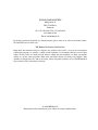
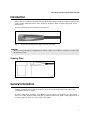
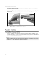
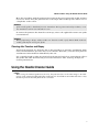
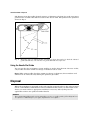
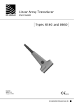
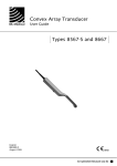
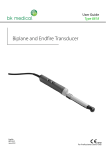
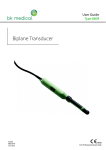
Linear Array Transducer
User Guide
Types 8559-S and 8659
English
BB0611-F
August 2006
WORLD HEADQUARTERS
Mileparken 34
DK-2730 Herlev
Denmark
Tel.:+45 44528100 / Fax:+45 44528199
www.bkmed.com
Email: [email protected]
If you have comments about the user documentation, please write to us at the email address above.
We would like to hear from you.
BK Medical Customer Satisfaction
Input from our customers helps us improve our products and services. As part of our customer
satisfaction program, we contact a sample of our customers a few months after they receive their
orders. If you receive an email message from us asking for your feedback, we hope you will be
willing to answer some questions about your experience buying and using our products. Your
opinions are important to us. You are of course always welcome to contact us via your BK Medical
representative or by contacting us directly.
© 2006 BK Medical
Information in this document may be subject to change without notice.
Linear Array Transducer Types 8559-S and 8659
Introduction
Scanning Plane
General Information
1
1
1
Caring for the Transducer
2
Cleaning and Disinfection
2
Starting Scanning
2
Connecting the Transducer
Changing Frequency
Using a Transducer Cover
Changing Orientation
3
3
3
3
Holding the Transducer for Intraoperative Scanning
3
Puncture Facilities
4
Puncture Guide Attachment UA1234
Mounting UA1234 to Transducer Types 8559-S and 8659
4
5
Performing Puncture and Biopsy
6
Cleaning after Puncture and Biopsy
7
Using the Needle Channel Guide
7
Using the Needle Slot Guide
8
Disposal
English BB 0611-F
August 2006
8
Linear Array Transducer Types 8559-S and
8659
Linear Array Transducer Types 8559-S and 8659
Introduction
This is the user guide for the Linear Array Transducer Types 8559-S and 8659, and must be
used together with Transducer Care, Cleaning & Safety which contains important safety
information.
8559-S and 8659 are intraoperative transducers.
Fig. 1.
Linear Array Transducer Types 8559-S and 8659
WARNING!
Do not use the transducer for applications where it may come in direct conductive contact with
the patient’s heart.
Scanning Plane
Fig. 2.
Scanning plane of Types 8559-S and 8659
General Information
Product specifications for this transducer can be found in the Product Data sheet that
accompanies this user guide.
Acoustic output data and data about EMC (electromagnetic compatibility) for this transducer are on the Technical Data CD that accompanies this user guide. A full explanation of
acoustic output is given in your scanner user guide.
1
8559-S and 8659 • Cleaning and Disinfection
WARNING
If at any time the scanner malfunctions, or the image is severely distorted or degraded, or
you suspect in any way that the scanner is not functioning correctly:
• Remove all transducers from contact with the patient.
• Turn off the scanner. Unplug the scanner from the wall and make sure it cannot be
used until it has been checked.
• Do not remove the scanner cover.
• Contact your B-K Medical representative or hospital technician.
WARNING
Always keep the exposure level (the acoustic output level and the exposure time) as low as
possible.
Caring for the Transducer
The transducer may be damaged during use or processing, so it must be checked before use
for cracks or irregularities in the surface. It should also be checked thoroughly once a month
following the procedure in Transducer Care, Cleaning & Safety.
Cleaning and Disinfection
To ensure the best results when using B-K Medical equipment, it is important to maintain
a strict regular cleaning routine.
Full details of cleaning and disinfection procedures can be found in the Transducer Care,
Cleaning & Safety booklet that accompanies this user guide. A list of disinfectants and disinfection methods that the transducer can withstand are listed in the Product Data sheet.
Sterile covers are available. See the Product Data sheet for more details.
WARNING
Users of this equipment have an obligation and responsibility to provide the highest
degree of infection control possible to patients, co-workers and themselves. To avoid cross
contamination, follow all infection control policies for personnel and equipment established for your office, department or hospital.
Caution
Keep all plugs and sockets absolutely dry at all times.
Starting Scanning
All equipment must be cleaned and disinfected before use.
2
8559-S and 8659 • Holding the Transducer for Intraoperative Scanning
Connecting the Transducer
WARNING
Keep all plugs and sockets absolutely dry at all times.
The transducer is connected to the scanner using the array Transducer Socket on the scanner. To connect, the transducer plug’s locking lever should first be in a horizontal position.
Align the plug to the scanner socket and insert securely. Turn the locking lever clockwise to
lock in place.
When connected the transducer complies with Type B requirements of EN60601-1 (IEC
60601-1).
Changing Frequency
The Multi-Frequency Imaging (MFI) facility enables you to select the scanning frequency.
See the applicable scanner user guide for instructions. The selected frequency is displayed
at the top of the screen.
Using a Transducer Cover
The transducer should be enclosed in a transducer cover or a standard condom. See the
Product Data sheet for a list of available transducer covers.
Note: Sterile, disposable sheaths are recommended for intraoperative use. In the United
States of America, it is recommended that probe sheaths have been market-cleared. In Canada, use only licensed probe sheaths.
WARNING
Because of reports of severe allergic reactions to medical devices containing latex (natural
rubber), FDA is advising health-care professionals to identify their latex-sensitive patients
and be prepared to treat allergic reactions promptly.
Note: For Intraoperative Applications
Apply sterile gel to the tip of the transducer or fill the cover with 1 to 2ml of sterile water.
This improves the screen images by preventing image artifacts caused by air bubbles.
Pull the transducer cover over the transducer.
WARNING
Use only water-soluble agents or gels. Petroleum or mineral oil-based materials may harm
the cover material.
Changing Orientation
To change the orientation of the image on the monitor, refer to the applicable scanner user
guide for instructions.
Holding the Transducer for Intraoperative Scanning
Types 8559-S and 8659 are used for intraoperative scanning.
3
8559-S and 8659 • Puncture Facilities
Pull the transducer cover over the transducer and irrigate the organ to be scanned with
0.9% sterile physiological saline.
When using Types 8559-S and 8659, hold the transducer between two or three fingers (see
Fig. 3.) and move your hand smoothly over the surface of the organ to produce the best
screen image.
Fig. 3.
Holding Types 8559-S and 8659 for scanning
Puncture Facilities
Puncture Guide Attachment UA1234
Puncture and biopsy are possible using puncture attachment UA1234 with Types 8559-S
and 8659. The puncture attachment is illustrated in the following pages with a brief description of its use and operating instructions.
WARNING!
It is essential for the patient’s safety that only the correct puncture attachment is used with
Types 8559-S and 8659. Never use unauthorized combinations of transducers and puncture
attachments or other manufacturers’ puncture attachments.
4
8559-S and 8659 • Puncture Facilities
Fig. 4.
The puncture attachment UA1234
This plastic puncture attachment (see Fig. 4.) has a needle channel and a slot guide to
accommodate different size needles and insertions at different angles.
The needle channel guide has an inner diameter of 2.1mm to fit needles up to 14 Gauge.
The needle channel guide is angled at 0° to the transducer’s image plane and 30° towards
the mid-axis of the scan image.
You can use the needle slot guide in UA1234 to insert needles at angles other than 30°. Only
needles less than 1.2mm (18 Gauge) in diameter can be used.
All parts of the puncture attachment can be autoclaved or disinfected by immersion in a
suitable solution. Do not exceed 20 cycles.
Mounting UA1234 to Transducer Types 8559-S and 8659
To mount UA1234 (as shown in Fig. 5.):
1. Hold the transducer in your left hand with the cable towards you and the linear array
facing down.
2. Hold UA1234 in your right hand, with the channel and slot guides to the right and the
flat surface facing up. It may be helpful to hold the extending part of UA1234 (containing the channel and slot guides) between your right thumb and forefinger.
3. Align UA1234 with the transducer.
4. Gently insert the transducer into UA1234 and press firmly together until you hear a
’’click’’.
5. Ensure UA1234 is securely in position.
5
8559-S and 8659 • Performing Puncture and Biopsy
needle channel guide
needle slot guide
Fig. 5.
UA1234 mounted on Types 8559-S and 8659
Performing Puncture and Biopsy
WARNING
It is essential for the patient’s safety that only the correct puncture attachments, as described
in this guide, are used. Never use unauthorized combinations of transducers and puncture
attachments or other manufacturers puncture attachments.
Before beginning a puncture or biopsy procedure, always check that the type number of the
transducer and the type number or description of the puncture attachment match exactly
those displayed on the scanner monitor.
WARNING
The puncture line on the scan image is an indication of the expected needle path. The needle
tip echo should be monitored at all times so any deviation from the desired path can be corrected.
Cover the transducer with a sterile transducer cover.
If the transducer cover is damaged when attaching the puncture attachment, replace it with
a new cover.
Note: Sterile, disposable sheaths are recommended for intraoperative use; and in the U.S.A.
it is recommended that probe sheaths have been market-cleared. In Canada, use only
licensed probe sheaths.
See the Product Data sheet for a list of available transducer covers.
Press the scanner Puncture or Biopsy control button to superimpose a puncture line on the
scan image.
If more than one puncture line is available, refer to the applicable scanner user guide for
instructions on how to change which one appears.
6
8559-S and 8659 • Using the Needle Channel Guide
Move the transducer until the puncture line transects the target. Insert the needle and monitor it as it moves along the puncture line to the target. The needle tip echo will be seen as
a bright dot on the screen.
WARNING
If the needle guide is detached from the transducer during interventional procedures, cover
the transducer with a new transducer cover.
To remove the puncture line from the scan image, refer to the applicable scanner user guide
for instructions.
WARNING
When performing a biopsy, always make sure that the needle is fully drawn back inside the
needle guide before moving the probe.
Cleaning after Puncture and Biopsy
If biological materials are allowed to dry on the transducer or puncture attachments, disinfection and sterilization processes may not be effective. Therefore, you must clean puncture
attachments and transducers immediately after use.
Use a suitable brush to make sure that biological material and gel are removed from all needle guides and other channels and grooves. See Transducer Care, Cleaning & Safety for
cleaning instructions.
Using the Needle Channel Guide
Caution:
When using the channel guide (not the slot), the puncture line on the scan image is an indication of the expected needle path. The needle tip echo should be monitored at all times so any
deviation from the desired path can be corrected.
7
8559-S and 8659 • Disposal
The distance from the needle channel entrance of UA1234 to the first dot on the scan image
puncture line is 34mm. The distance between the dots is 5mm. The puncture line pattern is
shown in Fig. 6.
Fig. 6.
Puncture lines for UA1234. This illustration shows the angles for both the channel
guide (dotted line) 30° and the slot guide (dashed line) up to 65°
Using the Needle Slot Guide
You can use the slot in UA1234 to insert needles at angles other than 30°. Because of this,
only needles less than 1.2mm (18 Gauge) in diameter can be used.
Note: When using needles less than 1.2mm (18 Gauge) in diameter, the transducer and
UA1234 can be removed easily during the puncture procedure.
Disposal
When the transducer is scrapped at the end of its life, national rules for the relevant material in each individual land must be followed. Within the EU, when you discard the transducer, you must send it to appropriate facilities for recovery and recycling. See the
applicable scanner user guide for further details.
WARNING
For contaminated disposals such as transducer covers or needle guides, follow disposal control policies established for your office, department or hospital.
8