1
Installation, user and
maintenance manual
GAHP-GS/WS
water/water gas absorption heat pump
powered by gas and renewable energy
Revision: M
Code: D-LBR509
This manual has been drawn up and printed by Robur S.p.A.; whole or partial reproduction of
this manual is prohibited.
The original is filed at Robur S.p.A.
Any use of this manual other than for personal consultation must be previously authorised by
Robur S.p.A.
The rights of those who have legitimately filed the registered trademarks contained within this
publication are not affected.
With the aim of continuously improving the quality of its products, Robur S.p.A. reserves the
right to modify the data and contents of this manual without prior notice.
Installation, user and maintenance manual – GAHP-GS/WS
Index of contents
1PREFACE������������������������������������������������������������������������������������������������������������4
2SAFETY WARNINGS������������������������������������������������������������������������������������������5
3OVERVIEW AND TECHNICAL FEATURES��������������������������������������������������������8
3.1GENERAL INFORMATION������������������������������������������������������������������������������������������������������������������������������������������������������������ 8
3.2NOTES ON OPERATION OF THE APPLIANCE����������������������������������������������������������������������������������������������������������������������10
3.3TECHNICAL MANUFACTURING CHARACTERISTICS��������������������������������������������������������������������������������������������������������11
3.4TECHNICAL DATA������������������������������������������������������������������������������������������������������������������������������������������������������������������������12
3.5DIMENSIONS AND SERVICE PANEL���������������������������������������������������������������������������������������������������������������������������������������15
4NORMAL OPERATION������������������������������������������������������������������������������������17
4.1START UP (AND SHUT DOWN)������������������������������������������������������������������������������������������������������������������������������������������������17
4.2ON-BOARD ELECTRONICS��������������������������������������������������������������������������������������������������������������������������������������������������������19
4.3RESET OPERATIONS��������������������������������������������������������������������������������������������������������������������������������������������������������������������22
4.4OPERATING SETTINGS���������������������������������������������������������������������������������������������������������������������������������������������������������������23
4.5PROLONGED PERIODS OF DISUSE����������������������������������������������������������������������������������������������������������������������������������������24
5HYDRAULIC INSTALLATION��������������������������������������������������������������������������26
5.1GENERAL INSTALLATION PRINCIPLES����������������������������������������������������������������������������������������������������������������������������������26
5.2POSITION OF THE APPLIANCE������������������������������������������������������������������������������������������������������������������������������������������������26
5.3HYDRAULIC CONNECTIONS����������������������������������������������������������������������������������������������������������������������������������������������������28
5.4GAS SUPPLY����������������������������������������������������������������������������������������������������������������������������������������������������������������������������������30
5.5CONDENSATE DISCHARGE�������������������������������������������������������������������������������������������������������������������������������������������������������31
5.6FILLING OF HYDRAULIC CIRCUIT�������������������������������������������������������������������������������������������������������������������������������������������34
5.7EXHAUST FLUE GAS��������������������������������������������������������������������������������������������������������������������������������������������������������������������37
5.8PROGRAMMING OF HYDRAULIC PARAMETERS���������������������������������������������������������������������������������������������������������������42
5.9SAFETY VALVE DISCHARGE ROUTING����������������������������������������������������������������������������������������������������������������������������������43
6ELECTRICAL INSTALLATION��������������������������������������������������������������������������45
6.1ELECTRICAL DIAGRAM OF THE APPLIANCE�����������������������������������������������������������������������������������������������������������������������49
6.2HOW TO CONNECT THE APPLIANCE ELECTRICALLY�������������������������������������������������������������������������������������������������������50
6.3TYPE A (COMFORT CONTROL PANEL)����������������������������������������������������������������������������������������������������������������������������������50
6.4TYPE B (DDC)��������������������������������������������������������������������������������������������������������������������������������������������������������������������������������60
6.5TYPE C (Consent switch)�����������������������������������������������������������������������������������������������������������������������������������������������������������70
6.6HOW TO RESET THE FLAME CONTROLLER FROM REMOTE������������������������������������������������������������������������������������������71
7INITIAL ACTIVATION AND MAINTENANCE��������������������������������������������������73
7.1PROCEDURE FOR FIRST START UP�����������������������������������������������������������������������������������������������������������������������������������������73
7.2MAINTENANCE�����������������������������������������������������������������������������������������������������������������������������������������������������������������������������77
7.3CHANGE OF GAS TYPE��������������������������������������������������������������������������������������������������������������������������������������������������������������78
8ACCESSORIES��������������������������������������������������������������������������������������������������81
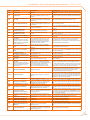
9OPERATING CODES/TROUBLESHOOTING���������������������������������������������������82
9.1OVERVIEW AND OPERATING CODES/TROUBLESHOOTING������������������������������������������������������������������������������������������82
����������������������������������������������������������������������95
DE
3
1PREFACE
This Installation, user and maintenance manual is a guide to the installation and operation of the Air-Water gas absorption heat pump GAHP-GS/WS.
This manual is specifically intended for:
• final users for the operation of the appliance according to their own
requirements;
• Installation technicians (hydraulic and electrical) for a correct installation of the
appliance.
The manual also contains:
• a section that describes all the operations necessary for the “first start-up” and for
the “gas change” of the appliance, as well as the main maintenance operations;
• an "ACCESSORIES" section with a description of accessories available and their respective reference codes.
• (IN CASE) one or more APPENDIX sections in which are reported some "specific"
information for a particular country.
References
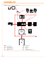
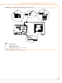
If the appliance is connected to a Comfort Control Panel (see detail CCP in Figure 6.4
Comfort Control Panel e Accessory → 48) it is switched on and controlled by the Comfort
Control Panel. In this case, refer to the manual supplied with it.
If the appliance is connected to a Direct Digital Controller (see Figure 6.3 CCI/DDC → 47)
and the DDC is in controller mode, activation and control of the appliance will occur exclusively by operating the DDC. In this case, refer to the manual supplied with it.
Definitions, terms and icons
APPLIANCE: this term refers to the gas absorption heat pump GAHP-GS and/or gas absorption heat pump GAHP-WS.
CCP: "Comfort Control Panel".
CCI: "Comfort Control Interface" device.
DDC: digital control panel (Direct Digital Controller).
TAC: Technical Assistance Centre (authorised by Robur S.p.A.).
SYSTEM COLD SIDE: this term refers to the renewable source plant (geothermal probes
or ground water).
SYSTEM HOT SIDE: this term refers to the primary hot water distribution system.
The icons in the edge of the manual have the following meanings:
= DANGER
= WARNING
= NOTE
= START OF OPERATING PROCEDURE
= REFERENCE to another part of the manual or other document
4
Installation, user and maintenance manual – GAHP-GS/WS
2SAFETY WARNINGS
Packing items (plastic bags, polystyrene foam, nails, etc.) must be kept out of the reach of
children, as they are potentially dangerous.
The appliance must only be used for the purposes for which it has been designed. Any
other use is considered inappropriate and therefore dangerous. The manufacturer does
not accept any contractual or extra-contractual liability for any damage caused by improper use of the appliance.
The appliance is not intended to be used by persons (including children) whose physical,
sensory and mental capacities are impaired, or who lack the necessary experience and
knowledge, unless they are supervised or instructed in its use by persons responsible
for their safety. Children must be supervised to ensure that they do not play with the
appliance.
The unit uses a water/ammoniac absorption cycle for hot/cold water production. The ammoniac is in water solution inside a sealed circuit tested for tightness by the manufacturer. In case of coolant leaks, switch off the electrical power and gas supplies only if this
can be done in total safety. Contact your Authorised Service Centre.
If installed indoors, the safety valve must be ducted. Refer to Chapter 5.9 SAFETY VALVE
DISCHARGE ROUTING → 43 of this manual for instructions. The unit MAY NOT BE OPERATED if the safety valve is not ducted.
Frequent topping up of the hydraulic with water can result in damage due to scale and
corrosion, depending on the quality of the water being used. Make sure the system is
water tight and that the expansion tank is operational.
Concentrations of chlorides or free chlorine in the circuit above the values given in Table
5.1 Chemical and physical parameters of water → 29 will damage the unit's water/ammonia exchanger.
Close the gas supply before working on the gas circuit. On completing work on the gas
circuit, check for leakages as required by established regulations.
Do not operate the appliance if dangerous conditions exist: odour of gas in the grid
or near the appliance; problems with the electrical/gas grid or hydraulic circuit; parts
of the appliance submerged in water or otherwise damaged; controls or safety components bypassed or defective. In these cases, ask for assistance to professionally qualified
personnel.
If you smell gas:
5
•
•
•
•
o not use electrical devices such as telephones, multimeters or other equipment
d
that can cause sparks next to the appliance;
shut off gas supply closing the isolation valve;
cut off electrical power opening the main breaker upstream of the appliance (to be
provided by the electrical installer in an appropriate panel);
ask for assistance to professionally qualified personnel from a telephone distant
from the appliance.
Moving parts, also during the appliance's start-up and shut-down cycles. Do not remove
guards. Make sure the appliance cannot be started up inadvertently.
POISONING HAZARD
Make sure the flue gas components are tight and compliant with established regulations.
After any intervention on these parts, check for tightness.
If the appliance is installed indoors, insufficient or non-conforming ventilation (see installation instructions) can result in hazardous leaks of combusted gases.
•
•
•
ake sure the ventilation and aeration outlets conform to the installation
M
instructions.
If the non-conformity cannot be resolved immediately, do not start up the
appliance.
Notify the plant operator of the non-conformity and any attendant hazards.
BURN HAZARD
The appliance contains numerous hot parts. Do not open up the appliance or touch the
fumes outlet pipe. If necessary, contact your Technical Assistance Centre.
The appliance has a sealed circuit classified as pressure equipment, i.e. with internal pressure higher than atmospheric pressure. The fluids contained in the sealed circuits are
harmful if swallowed or inhaled, or if they come into contact with the skin. Do not carry
out any operation on the sealed circuit or on its valves.
ELECTROCUTION HAZARD
•
•
•
se only approved components for the electrical connections, as specified by the
U
manufacturer.
Disconnect the electrical power supply before working on the appliance's internal
electrical equipment (electrical panel, motors, control board, etc.).
Make sure the appliance cannot be started up inadvertently.
The electrical safety of the appliance is ensured only when it is correctly connected to an
efficient grounding system, compilant with current safety regulations.
DAMAGE DUE TO AGGRESSIVE SUBSTANCES IN THE AIR SUPPLY
Hydrogenated hydrocarbons, which contain chlorine and fluorine compounds, will increase the corrosion of the unit.
6
Installation, user and maintenance manual – GAHP-GS/WS
Make sure the air supply is free of aggressive substances.
ACID CONDENSATE
Drain out the condensate produced during combustion as indicated in paragraph 5.5
CONDENSATE DISCHARGE → 31.
EXPLOSIVE/FLAMMABLE MATERIALS HAZARD
Do not use or store flammable materials (paper, solvents, paint, etc.) in the vicinity of the
appliance.
SUGGESTIONS FOR THE CLIENT
Stipulate a maintenance contract with an authorised specialist contractor for the annual
inspection of the appliance and maintenance when needed.
Maintenance and repairs may only be done a contractor legally authorised to work on
gas appliances and equipment.
Only accept and use original spare parts.
7
3OVERVIEW AND TECHNICAL FEATURES
In this section you will find general information, hints on the operating principle of the
appliance and its manufacturing features. This section also contains technical data and
dimensional drawings of the appliance.
3.1GENERAL INFORMATION
This manual is an integral and essential part of the product and must be delivered to the
user together with the appliance.
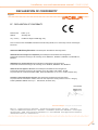
Conformity to CE standards
The absorption heat pumps of the GAHP series are certified as conforming to standard EN
12309-1 and -2 and comply with the essential requirements of the following Directives:
• Gas Directive 90/396/EEC and subsequent modifications and additions.
• Efficiency Directive 92/42/EEC and subsequent modifications and additions.
• Electromagnetic Compatibility Directive 89/336/EEC and subsequent modifications and additions.
• Low Voltage Directive 89/336/EEC and subsequent modifications and additions.
• "Machinery Directive" 2006/42/EC.
• Pressurised Equipment Directive 97/23/EEC and subsequent modifications and
additions.
• UNI EN 677 Specific requirements for condensing boilers with nominal thermal capacity up to 70 kW.
• EN 378 Refrigerating systems and heat pumps.
The emission values of nitrogen oxides (NOx) of gas absorption heat pumps of the GAHP
series are lower than 60 mg/kWh, in compliance with the requirements of the standard
RAL UZ 118 "Blauer Engel".
Information regarding the above EC certifications is given in Paragraph 3.4 TECHNICAL
DATA → 12, as well as on the Nameplate of the appliance itself.
Installation and regulatory references
On receiving the appliance at the installation site, before placing into final position, check
there are no signs of transportation damages of the external panels or packaging.
Packing materials must be removed only after the appliance has been positioned on site.
After removing the packing materials, ensure that the appliance is intact and complete.
Installation of the appliance may only be carried out by professionally qualified personnel
by i.e. firms qualified according to the current legislation of the country of installation.
"Professionally qualified personnel" means personnel with specific technical competence
in the sector of heating/cooling installations and gas appliances.
Installation of the appliance must be carried out in compliance with current local and
national regulations regarding the design, installation and maintenance of heating and
cooling installations and in accordance with the manufacturer's instructions.
In particular, current regulations regarding the following aspects must be respected:
• Gas equipment.
• Electrical equipment.
• Heating installations and heat pumps
8
Installation, user and maintenance manual – GAHP-GS/WS
•
E very other standard and regulation concerning the installation of equipment for
summer and winter air conditioning using gas fuel.
The manufacturer does not accept any contractual or extra-contractual liability for any
damage caused by errors in installation and/or failure to observe the abovementioned
regulations and the instructions supplied by the manufacturer itself.
Once the appliance is installed
The installer must provide the owner with a Declaration stating that the installation has
been completed in compliance with state-of-the-art practices, current national and local
regulations, and recommendations by the manufacturer.
Before contacting Technical Assistance for commissioning and first start-up, the installer
must ensure that:
• the electricity and gas grids characteristics correspond to the specifications on the
nameplate of the appliance;
• the gas supply pressure is compliant with the value reported in Table 5.2 Network
gas pressure → 31 (considering a tolerance of ±15%);
• the appliance is fed by the type of gas for which it is designed;
• the gas supply system and water distribution system are sealed;
• the gas and electricity supply systems are properly rated for the capacity required
by the appliance and are equipped with all safety and control devices required by
current regulations
Check that no safety and control devices are excluded, by-passed or not properly
working.
Initial activation procedure
The complete procedure for the first start up of the appliance must be carried out by an
authorized technician according to the instructions supplied by the manufacturer.
To carry out entire procedure correctly, follow the instructions in Paragraph 7.1 PROCEDURE FOR FIRST START UP → 73.
Warranty could be invalidated if the first start up is not carried out and validated by an
authorized technician.
Operation and maintenance of the appliance
To ensure the correct operation of the appliance and to avoid failures, control of the
switching on and off of the appliance must be done in line with the requirements of the
various types of installation.
• If the appliance is connected to the Comfort Control Panel (see Figure 6.4 Comfort
Control Panel e Accessory → 48 detail CCP), the appliance may be switched on and
off exclusively by the CCP itself.
• If the appliance is connected to the DDC (see Figure 6.3 CCI/DDC → 47), the appliance may be switched on and off exclusively by the DDC itself.
• If the appliance is NOT connected to a CCP/DDC, the appliance may be switched
on and off exclusively by a switch on the consent circuit.
9
The appliance must never normally be switched on and off by shutting off the power
supply upstream of the Controle Device (CCP, DDC or consent switch) before having used
the latter first and waited for the shutdown cycle to end (approximately 7 minutes). The
shutdown cycle terminates when the hydraulic pump switches off (no parts in motion).
Shutting off the power supply while the appliance is running can cause permanent damages to internal components!
If the appliance fails to operate correctly, with the consequent indication of the Machine code, follow the instructions of Paragraph 9.1 OVERVIEW AND OPERATING CODES/
TROUBLESHOOTING → 82.
In the event of failure of the appliance and/or breakage of any component, do not attempt to repair and/or restore operation; proceed as follows:
•
s hut off the appliance immediately (if possible and if no dangerous condition exists) through the controls (CCP, DDC or permissive switch) and wait for the end of
the cooling down cycle (around 7 minutes);
• immediately get in touch with Technical Assistance.
Proper ordinary maintenance ensures the efficiency and good operation of the appliance over time.
Carry out maintenance operations according to the instructions supplied by the
manufacturer.
For the maintenance of internal components of the appliance, contact Technical Assistance; for other maintenance requirements, see Paragraph 7.2 MAINTENANCE → 77.
Any repair of the appliance must be carried out by Technical Assistance, using only original spare parts.
Failure to observe the indications above may compromise the operation and safety of the
appliance, and may invalidate warranty.
If the appliance is to be disposed of, contact the manufacturer for its correct disposal.
If the appliance is to be sold or transferred to another owner, ensure that this “Installation,
user and maintenance manual” is handed over to the new owner and installer.
3.2NOTES ON OPERATION OF THE APPLIANCE
The appliance uses the water/ammoniac absorption thermodynamic cycle (H20 – NH3)
to produce hot water, drawing the required energy from the ground (GAHP-GS) or, in the
case of the GAHP-WS, from ground water.
The water/ammonia thermodynamic cycle used in the unit GAHP-GS/WS is realized in
a hermitically sealed circuit, directly verified by the manufacturer to ensure the perfect
tightness of all joints, thus making refrigerant top-ups completely unnecessary.
Description and general characteristics
The GAHP-GS/WS is a modulating condensation heat pump: the thermal power modulates from 100% to 50% depending on load, to ensure optimal comfort.
The water/water gas absorption heat pump GAHP-WS produces hot water to +65°C for
heating purposes and up to +70°C for sanitary hot water.
The geothermal absorption heat pump GAHP-GS is available in the following versions:
10
Installation, user and maintenance manual – GAHP-GS/WS
ersion HT: optimised for high temperature heating systems (radiators, fan coils);
V
it produces hot water to +65°C for heating purposes and up to +70°C for sanitary
hot water.
• Version LT: optimised for low temperature distribution systems (heating floor, low
temperature radiators); it produces hot water up to +55°C in heating mode and up
to +70°C in Domestic Hot Water mode.
The modulating function (both in terms of combustion and flow rate) combined with
fumes condensation results in efficiencies of up to 172%.
The GAHP-GS/WS can operate in ambient temperatures of 0°C to +45°C.
The GAHP heat pump can be controlled with the CCP/DDC or with a switch on the consent circuit.
During operation, combustion products are exhausted via the discharge terminal at the
left side of the appliance (see Figure 3.1 Size → 15). The fumes outlet must be connected
to a flue (for further details, see Paragraph 5.7 EXHAUST FLUE GAS → 37).
The appliance powered by 230 V 1N 50 Hz electrical power - .
•
3.3TECHNICAL MANUFACTURING CHARACTERISTICS
The appliance is supplied with the following technical manufacturing characteristics,
control and safety components:
• Steel sealed circuit, externally treated with epoxy paint.
• Sealed combustion chamber suited for type C installation.
• Metal mesh radiant burner equipped with ignition electrodes and flame detection
managed by an electronic flame control box.
• Titanium stainless steel shall-and-tube heat exchanger, with external insulation.
• Tube coil heat recovery [AISI 304L] (for acid condensate).
Control and safety components
• S61 electronic board with integrated microprocessor, LCD display and control
knob, complete with Mod10 auxiliary card to control thermal capacity and primary pump modulation (see Figures 6.1 Electronic board S61 → 46 and 6.2 Mod10
controller → 47).
• Primary circuit water flowmeter (hot side).
• Plant water flowmeter (cold side).
• Sealed circuit high temperature limit thermostat, with manual reset.
• Flue temperature thermostat 120 °C, with manual reset.
• Sealed circuit safety relief valve.
• Safety by-pass valve, between high and low pressure parts of the sealed circuit.
• Antifreeze functions for hydraulic circuit.
• Ionization flame control box.
• Double shutter electric gas valve.
• Condensate discharge sensor.
11
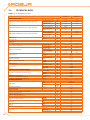
3.4TECHNICAL DATA
Table 3.1 – GS HT/LT technical data
GAHP GS LT
GAHP GS HT
%
kW
150 (1)
37,7 (1)
149 (1)
37,6 (1)
kW
12,4
12,6
%
kW
170 (1)
42,6 (1)
---
kW
17,0
--
%
kW
---
125 (1)
31,5 (1)
kW
--
7,9
OPERATION WHEN HEATING
OPERATING POINT B0W50* (Brine inlet 0°C, hot Water outlet +50°C)
OPERATING POINT B0W35* (Brine inlet 0°C, hot Water outlet +35°C)
OPERATING POINT B0W65* (Brine inlet 0°C, hot Water outlet +65°C)
Thermal capacity
G.U.E. gas usage efficiency
Thermal power delivered
Power recovered from
renewable source
G.U.E. gas usage efficiency
Thermal power delivered
Power recovered from
renewable source
G.U.E. gas usage efficiency
Thermal power delivered
Power recovered from
renewable source
Nominal (1013 mbar - 15°C)
true peak
NOx emission class
NOx emission
CO emission
Hot water delivery temperature
Hot water return temperature
Hot water flow rate
Hot water pressure drop
Ambient air temperature (dry bulb)
Thermal differential
gas consumption
maximum for heating
maximum for DHW
maximum heating
maximum for DHW
minimum temperature in
continuous operation**
nominal
maximum
minimum
for nominal water flow
(B0W50)
maximum
minimum
nominal
methane G20 (nominal)
G30 (nominal)
G31 (nominal)
kW
kW
ppm
ppm
°C
°C
°C
°C
25,7
25,2
5
25
36
55
65
70
45
55
60
°C
20
l/h
l/h
l/h
3250
30
3170
4000
1400
bar
0,49 (2)
°C
°C
°C
m3/h
kg/h
kg/h
45
0
10
2,72 (3)
2,03 (4)
2,00 (4)
l/h
l/h
l/h
bar
°C
°C
3020
4000
2000
0,51 (2)
45
RENEWABLE SOURCE OPERATING CONDITIONS
Renewable source water flow rate (with 25% glycol)
Renewable source pressure drop
Renewable source water return temperature
Renewable source delivery water temperature
ELECTRICAL SPECIFICATIONS
Power supply
nominal (B0W50)
maximum
minimum
at nominal flow rate
maximum
minimum
Voltage
TYPE
Frequency
Electrical power absorption
Degree of protection
INSTALLATION DATA
Level of acoustic pressure at 10 meters (maximum)
Minimum storage temperature
Maximum operating pressure
Maximum condensation water flow rate
Water content inside the apparatus
Water fitting
Gas fitting
nominal
IP
HOT SIDE
COLD SIDE
TYPE
thread
TYPE
thread
Safety valve outlet channel fitting
Fume outlet
12
Diameter (∅)
Residual head
Product configuration
V
50 Hz
supply
kW
dB(A)
°C
bar
l/h
l
l
"G
"G
"G
mm
Pa
-10
-5
230
SINGLE PHASE
50
0,47 (5)
X5D
39 (7)
-30
4
4,0
4
3
F
1 1/4
F
3/4
1 1/4
80
80
C63
Installation, user and maintenance manual – GAHP-GS/WS
GAHP GS LT
Size
Weight
GENERAL INFORMATION
INSTALLATION MODE
COOLING FLUID
MAXIMUM PRESSURE OF THE COOLING CIRCUIT
* data tested by VDE and DVGW-Forschungsstelle.
** in transient operation, lower temperatures are allowed
GAHP GS HT
width
height
depth
In operation
mm
mm
mm
kg
848 (6)
1278
690
300
AMMONIA R717
WATER H2O
kg
kg
bar
C13, C33, C43, C53, C63, C83, B23P, B33
7
10
35
Notes:
1. As per EN12309-2 evaluated on actual thermal capacity. For operating conditions
other than nominal, refer to the Design Manual.
2. For flow rates different from the nominal refer to the Design Manual.
3. PCI 34.02 MJ/m3 (1013 mbar – 15 ° C).
4. PCI 46.34 MJ/kg (1013 mbar – 15 ° C).
5. ± 10% depending on power voltage and absorption tolerance of electric motors.
6. Overall dimensions excluding fumes pipes (see Figure 3.1 Size → 15).
7. Free field, frontal, directionality factor 2.
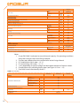
Table 3.2 – WS technical data
GAHP WS
OPERATION WHEN HEATING
OPERATING POINT W10W50
OPERATING POINT W10W65
Thermal capacity
G.U.E. gas usage efficiency
Thermal power delivered
Power recovered from
renewable source
G.U.E. gas usage efficiency
Thermal power delivered
Power recovered from
renewable source
Nominal (1013 mbar - 15°C)
true peak
NOx emission class
NOx emission
CO emission
Hot water delivery temperature
Hot water return temperature
Hot water flow rate
Hot water pressure drop
Ambient air temperature (dry bulb)
Thermal differential
gas consumption
maximum for heating
maximum for DHW
maximum heating
minimum temperature in
continuous operation**
nominal
maximum
minimum
for nominal water flow
rate(W10W50)
maximum
minimum
nominal
methane G20 (nominal)
G30 (nominal)
G31 (nominal)
%
kW
166 (1)
41,6 (1)
kW
16,6
%
kW
143 (1)
35,8 (1)
kW
11,5
kW
kW
ppm
ppm
°C
°C
°C
25,7
25,2
5
25
36
65
70
55
°C
20
l/h
l/h
l/h
3570
4000
1400
bar
0,57 (2)
°C
°C
°C
m3/h
kg/h
kg/h
45
0
10
2,72 (3)
2,03 (4)
2,00 (4)
l/h
l/h
l/h
bar
°C
°C
2850
4700
2300
0,38 (2)
45
3
RENEWABLE SOURCE OPERATING CONDITIONS
Renewable source water flow rate
Renewable source pressure drop
Renewable source water return temperature
Renewable source delivery water temperature
ELECTRICAL SPECIFICATIONS
nominal (W10W50)
maximum
minimum
at nominal flow rate
maximum
minimum
13
GAHP WS
Voltage
TYPE
Power supply
Frequency
Electrical power absorption
Degree of protection
INSTALLATION DATA
Level of acoustic pressure at 10 meters (maximum)
Minimum storage temperature
Maximum operating pressure
Maximum condensation water flow rate
nominal
IP
Water fitting
Gas fitting
Weight
GENERAL INFORMATION
50
mm
mm
mm
kg
kg
kg
bar
C13, C33, C43, C53, C63,
C83, B23P, B33
7,7
10
35
INSTALLATION MODE
AMMONIA R717
WATER H2O
COOLING FLUID
0,47 (5)
X5D
39 (7)
-30
4
4,0
4
3
F
1 1/4
F
3/4
1 1/4
80
80
C63
848 (6)
1278
690
300
"G
"G
mm
Pa
Diameter (∅)
Residual head
Product configuration
width
height
depth
In operation
Size
50 Hz
supply
kW
"G
Safety valve outlet channel fitting
Fume outlet
230
SINGLE PHASE
dB(A)
°C
bar
l/h
l
l
HOT SIDE
COLD SIDE
TYPE
thread
TYPE
thread
Water content inside the apparatus
V
MAXIMUM PRESSURE OF THE COOLING CIRCUIT
** in transient operation, lower temperatures are allowed.
Notes:
1. As per EN12309-2 evaluated on actual thermal capacity. For operating conditions
other than nominal, refer to the Design Manual.
2. For flow rates different from the nominal refer to the Design Manual.
3. PCI 34.02 MJ/m3 (1013 mbar – 15 ° C).
4. PCI 46.34 MJ/kg (1013 mbar – 15 ° C).
5. ± 10% depending on power voltage and absorption tolerance of electric motors.
6. Overall dimensions excluding fumes pipes (see Figure 3.1 Size → 15).
7. Free field, frontal, directionality factor 2.
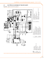
Table 3.3 – PED data
GAHP GS LT
GAHP GS HT
GAHP WS
PED data
COMPONENTS UNDER PRESSURE
TEST PRESSURE (IN AIR)
SAFETY VALVE PRESSURE CALIBRATION
FILLING RATIO
"SEALED SYSTEM" TARE
FLUID GROUP
14
Generator
Leveling chamber
Evaporator
Cooling volume transformer
Absorber/condenser
Cooling absorber solution
Solution pump
l
l
l
l
l
l
l
bar g
bar g
kg of
NH3/l
kg
18,6
11,5
3,7
4,5
3,7
6,3
3,3
55
35
0,137
0,159
165
GROUP 1°
Installation, user and maintenance manual – GAHP-GS/WS
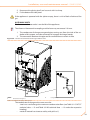
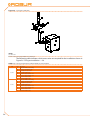
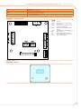
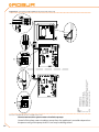
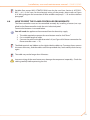
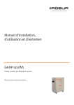
3.5DIMENSIONS AND SERVICE PANEL
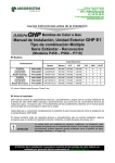
Figure 3.1 – Size
LEGEND
AFumes outlet dia 80
BCombustion air intake dia 80
CManual reset fumes thermostat
DPower cable input
ECooling fan
FAppliance on indicator
GGas fitting dia. ¾"
HHot water return dia. 1"¼
LRenewable source water return dia. 1"¼
MRenewable source water delivery dia. 1"¼
NHot water delivery dia. 1"¼
QSafety valve outlet ducting dia. 1"¼
15
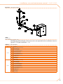
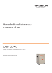
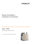
Figure 3.2 – Outdoor unit dimensions
LEGEND
AFumes outlet dia 80
BCombustion air intake dia 80
CManual reset fumes thermostat
DPower cable input
ECooling fan
16
FAppliance on indicator
GGas fitting dia. ¾"
HHot water return dia. 1"¼
LRenewable source water return dia. 1"¼
MRenewable source water delivery dia. 1"¼
NHot water delivery dia. 1"¼
Installation, user and maintenance manual – GAHP-GS/WS
4NORMAL OPERATION
In this section you will find all the indications necessary for the activation, regulation and
control of operation of the appliance depending on the type of installation and control
setup.
• TYPE
A: controlled by CCP (see Figure 6.4 Comfort Control Panel e Accessory → 48,
detail CCP).
• TYPE
B: controlled by DDC (see Figure 6.3 CCI/DDC → 47).
• TYPE
C: controlled by consent switch (e.g. on-off switch, ambient thermostat, timer, etc.).
4.1START UP (AND SHUT DOWN)
Efficient operation and long life of the appliance depend largely on its correct use!
Before activating the appliance, check that:
• the gas valve is open;
• the appliance is powered electrically: the general electrical switch (GS) must be in
the «ON» position;
• power supply to the CCP/DDC (if provided) is on;
• the installation technician has ensured that the hydraulic circuit is supplied in the
correct conditions.
If these conditions are satisfied, it is possible to proceed with activation.
TYPE A: APPLIANCE CONNECTED TO COMFORT CONTROL PANEL (CCP)
If the appliance is connected to a Comfort Control Panel (see detail CCP in Figure 6.4
Comfort Control Panel e Accessory → 48) it is switched on and controlled by the Comfort
Control Panel. In this case, refer to the manual supplied with it.
The appliance must never normally be switched on and off by shutting off the power
supply upstream of the Comfort Control Panel before having used the latter first and
waited for the shutdown cycle to end (approximately 7 minutes). The shutdown cycle
terminates when the hydraulic pump switches off (no parts in motion).
Shutting off the power supply while the appliance is running can cause permanent damages to internal components!
TYPE B: APPLIANCE CONNECTED TO A DIRECT DIGITAL CONTROLLER (DDC)
If the appliance is connected to a Direct Digital Controller (see Figure 6.3 CCI/DDC → 47)
and the DDC is in controller mode, activation and control of the appliance will occur exclusively by operating the DDC. In this case, refer to the manual supplied with it.
The appliance must never normally be switched on and off by shutting off the power
supply upstream of the DDC before having used the latter first and waited for the shut
down cycle to end (approximately 7 minutes). The shutdown cycle terminates when the
hydraulic pump switches off (no parts in motion).
Shutting off the power supply while the appliance is running can cause permanent damages to internal components!
17
TYPE C: STANDALONE APPLIANCE
Standalone appliances must be activated and deactivated only by means of the consent
switch provided by the electrical installation technician.
According to requirements, this consent switch may be an on/off button, an ambient
thermostat, a programmable timer, or one or more voltage free contacts controlled by
another process. For details about the type of on/off command installed, contact the
plant’s electrical installation technician.
The appliance must never normally be switched on and off by shutting off the power
supply upstream of the Controle Device (CCP, DDC or consent switch) before having used
the latter first and waited for the shutdown cycle to end (approximately 7 minutes). The
shutdown cycle terminates when the hydraulic pump switches off (no parts in motion).
Shutting off the power supply while the appliance is running can cause permanent damages to internal components!
Start up
Switch on the appliance by means of the on/off command (placing it in the "ON"
position).
Shut down
Switch off the appliance via the on/off command (placing it in the "OFF" position).
The shutdown cycle takes approximately 7 minutes to complete.
The on/off command is essential! Do not switch the appliance on or off by connecting it
to or disconnecting it from the power supply directly, as this may be a source of danger
and in any case damage the appliance or the plants connected to it.
Visualising and clearing of operating codes
Operating codes can be generated:
• by the S61 on-board controller;
• by the CCP/DDC (if present).
The operating codes generated by the S61 controller are displayed on its screen and can
also be viewed on the CCI (if present) or DDC (if present).
Operating codes generated by the controller can be cleared through the board itself or
from the CCI/DDC (if fitted and allowed).
For a description of the operating codes generated by the electronic board and how to
reset them, refer to the list of operating codes contained in Table 9.1 TABLE OF OPERATING CODES generated by the S61 electronic board (firmware version 3.024) → 82.
The controller (see Figure 6.1 Electronic board S61 → 46) is located inside the electrical
panel of the appliance and the display may be viewed through the viewing hole on the
front panel of the unit itself.
The Machine Codes generated by the CCI/DDC may only be viewed on the display of the
CCI/DDC and may be cleared only through the CCI/DDC.
18
Installation, user and maintenance manual – GAHP-GS/WS
For the operating codes generated by the CCP/DDC, refer to the manuals supplied with
the unit.
Operating codes generated by the electronic board during the start-up of the
appliance
If the appliance remains inactive for a prolonged period, it is possible that air is present in
the gas pipes. In this case, activation fails and the appliance reports the operating code:
"u_12" - flame controller arrest (temporary) (see Paragraph 9.1 OVERVIEW AND OPERATING CODES/TROUBLESHOOTING → 82) and after a brief interval the appliance automatically launches the start up procedure again. If code (u_12) is signalled 3 times on successive activation attempts, the code persists, the appliance locks out the flame controller
and displays the following operating code: "E_12" - flame controller arrest (see Paragraph
9.1 OVERVIEW AND OPERATING CODES/TROUBLESHOOTING → 82). In this case reset is
not automatic.
To restore operation of the appliance, carry out a reset of the flame control unit via menu
2 of the controller: the procedure is illustrated in Paragraph 4.3 RESET OPERATIONS → 22.
After it is reset, the appliance will make a new attempt to activate.
If the appliance locks out several times, contact a Robur TAC by calling the Technical Service Department of Robur S.p.A. (tel. +39.035.888111).
When activation is successful, the appliance is managed by the on-board controller (see
following paragraph).
4.2ON-BOARD ELECTRONICS
The following descriptions refer to the S61 controller with firmware version 3.024.
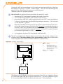
The appliance is fitted with an S61 microprocessor controller with Mod10 modulation
controller mounted above it (see Figure 4.1 On-board controller → 20).
The S61 controller, in the electrical panel, controls the appliance and displays data, messages and operating codes.
Programming, control and monitoring of the appliance take place by interacting with the
display A and knob B shown in Figure 4.1 On-board controller → 20. The CAN-BUS port
connects one or several appliances to the CCP (if present) or a DDC (if present).
The Mod10 controller (detail D in Figure 4.1 On-board controller → 20) is used for combustion modulation and variable rate pump control.
19
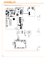
Figure 4.1 – On-board controller
LEGEND
A4 digit display
BKnob
CCAN port
DMod10 controller
S61 + Mod10
Description of menu of S61 controller
The parameters and settings of the appliance are grouped in the menus shown on the
controller’s display:
Table 4.1 – Menu of electronic board
MENU
MENU DESCRIPTION
Menu 0
VIEW DATA (TEMPERATURE, VOLTAGE, PUMP SPEED, ECC...)
Menu 1
VIEW ALL PARAMETERS
Menu 2
ENTER ACTIONS
Menu 3
USER SETTINGS (THERMOSTATING, SET-POINT, T. DIFFERENTIAL)
Menu 4
INSTALLATION TECHNICIAN SETTINGS
Menu 5
TECHNICAL ASSISTANCE CENTRE SETTINGS
Menu 6
TECHNICAL ASSISTANCE CENTRE SETTINGS (MACHINE TYPE)
Menu 7
VIEW DIGITAL IMPUTS
Menu 8
(MENU NOT USED)
E
EXIT MENU
Menu list of electronic board
THE DISPLAY SHOWS
0.
1.
2.
3.
4.
5.
6.
7.
8.
E.
Menus 0, 1 and 7 are Viewing Menus: they only allow the information displayed to be
read, and not modified. Menu 0 shows the appliance operating data in real time. Menu 1
shows the parameters that characterise the operation of the appliance and their current
values.
Menu 7 is to be used ONLY by the Robur TAC.
To view the information contained in these menus, proceed as illustrated in the paragraph "How to acces the menus".
Menu 2 is an execution menu: it allows the operations of resetting the flame control unit,
error reset and the manual defrosting command to be performed.
To perform these procedures, see Paragraph 4.3 RESET OPERATIONS → 22.
Menu 3 is a Settings Menu: it allows the values displayed to be set. The correct values of
these parameters, for optimum performance of the appliance with the plant to be used
20
Installation, user and maintenance manual – GAHP-GS/WS
connected, have already been set during installation. To set new values for the parameters, see Paragraph 5.8 PROGRAMMING OF HYDRAULIC PARAMETERS → 42.
Menus 4, 5, 6 and 7 exclusively concern the installation technician and Robur’s authorized Technical Assistance Centre.
Menu 8 may currently be selected, but not used.
Display and knob
The controller’s display can be viewed through the glass of the viewing aperture on the
front panel of the appliance.
Upon activation, all of the LEDs of the display light up for approximately three seconds,
and then the name of the board, S61, appears. After around 15 seconds after the appliance powers up, the appliance starts running if the required consent is available.
During correct operation the display shows, alternately, the following information: outlet
water temperature, inlet water temperature, and the difference between the two water
temperatures (see Table 4.2 Operating information → 21).
Table 4.2 – Operating information
OPERATING MODE: HEATING
PARAMETER
Hot outlet water temperature
Hot inlet water temperature
Differential Temperature (outlet - inlet)
Example of data visualised on display: water temperature and differential
THE DISPLAY SHOWS
50.0
40.0
10.0
If there are operating problems, the display shows, sequentially, the operating codes corresponding to the problem detected. A list of these codes with their description and the
procedure to follow to bring the appliance back to correct operation is provided in Paragraph 9.1 OVERVIEW AND OPERATING CODES/TROUBLESHOOTING → 82.
The knob is used to display or set parameters, or to execute actions/commands (e.g.: a
function or reset), when permitted.
HOW TO ACCESS THE MENUS
• To use the knob with the special key supplied with the appliance:
You will need: the appliance's electrical power switches set to "ON"; the controller's display sequentially shows the operating data (temperature, delta T) regarding the current
mode (e.g.: heating) and any active operating codes ("u/E...").
1. R
emove the front panel by removing the fixing screws.
2. Remove the cover of the electrical panel to access the knob.
3. Use the special key through the hole to operate the knob and access the controller’s menus and parameters.
4. To display the menus just press the knob once: the display shows the first menu:
"0." (= menu 0).
5. The display shows “0.”. To display the other menus, turn the knob clockwise; The
display will read, in order: "1.", "2.", "3.", "4.", "5.", "6.", "7.", "8." and "E" (see Table 4.1
Menu of electronic board → 20).
6. To display the parameters in a given menu (for example, menu 0), turn the knob
until it displays the menu in question (in the example: "0.") and press the knob: the
display will show the first of the menu’s parameters, in this example "0.0" or "0.40"
(= menu 0, parameter "0" or "40").
21
7. I n the same way: turn the knob to scroll through content (menus, parameters, actions), press the knob to select/confirm the content (access a menu, display/set
a parameter, execute an action, quit or return to the previous level). For example,
to quit the menus, turn the knob to scroll through menus "0.", "1.", "2." etc. until the
controller displays the quit screen "E"; now press the knob to quit.
In the case of menus 0 and 1, the user can view any parameter. For information about
menu 2, refer to Paragraph 4.3 RESET OPERATIONS → 22. To set the parameters of menu
3, refer to Paragraph 5.8 PROGRAMMING OF HYDRAULIC PARAMETERS → 42. The other
menus are not for the User: the information in these menus is dealt with in the sections
dedicated to the installation technician or Robur TAC.
The special key allows the knob of the electronic board to be operated without opening
the cover of the electrical panel, so that operators are protected from live components.
When the necessary settings have been completed, put away the special key, replace the
cap on the aperture of the electrical panel and refit the front panel of the appliance.
4.3RESET OPERATIONS
There are several possible reasons why the appliance may have error status and therefore
its operation arrested; such an error situation does not necessarily correspond to damage
or malfunction on the part of the appliance. The cause that has generated the error may
be temporary: for example, presence of air in the gas supply line or temporary power
failure.
The appliance can be reset with controller menu 2, the Comfort Control Panel (if present)
or the DDC (if present). In these two latter cases, refer to their documentation.
Reset appliance controller
The Table 4.3 Menu 2 → 22 shows the actions available in menu 2.
For regulatory reasons, the flame controller reset is in a dedicated voice of menu.
Table 4.3 – Menu 2
ACTION
0
1
3
4
5
E
REQUIRED FOR EXECUTION
Reset flame controller arrest
Reset other operating codes
Timed forcing to minimum power
Timed forcing to maximum power
Regulation of power
(EXIT MENU)
SHOWN ON DISPLAY AS
2. 0
2. 1
2. 3
2. 4
2. 5
2. E
The general operating codes of the unit's controller can be reset with actions "0" and "1".
Actions "3", "4" and "5" are used to regulate the combustion parameters or for gas type
changeovers, and are thus for use only by the installation technician or Robur TAC (for
other information refer to Paragraph 7.1 PROCEDURE FOR FIRST START UP → 73).
RESET FLAME CONTROLLER (ACTION "0"):
Reset flame controller arrest; this may be used when the appliance is first activated, see
Paragraph 4.1 START UP (AND SHUT DOWN) → 17, when the appliance is in a permanent
locked condition or after a long period of disuse (see Paragraph 4.5 PROLONGED PERIODS OF DISUSE → 24).
You will need: access to the electrical panel, see Paragraph “Display and knob”.
22
Installation, user and maintenance manual – GAHP-GS/WS
To reset the flame control unit select menu 2, as indicated in the Paragraph "Accessing
the Menus"; then proceed as follows:
1. The display shows: "2." press the knob to access the menu. The display initially
shows item "2. 0".
2. Press the knob to display the flashing reset request: "reS1".
3. Press the knob again to reset the flame controller. The reset request stops flashing,
and again the display shows "2. 0". The reset operation has been performed.
4. To quit the menu, turn the knob clockwise until the "2. E" is displayed. Now press
the knob to return to menu selection: "2.".
5. To exit the menu selection and return to the normal visualisation of the parameters
of the appliance, turn the knob clockwise until "E" displays; press the knob to quit.
At this point, if the display does not signal any other operating codes, put away the special key, replace the electrical panel cover and refit the front panel.
RESET OTHER OPERATING CODES (ACTION "1"):
Reset other appliance errors; this is required to reset any errors which may occur during
operation.
You will need: access to the electrical panel, see Paragraph “Display and knob”.
To reset the controller errors, select menu 2, as indicated in the Paragraph "Accessing the
Menus"; Then:
1. The display shows: "2." press the knob to access the menu. The display initially
shows item "2. 0".
2. Turn the knob clockwise to display item "2. 1".
3. Press the knob to display the flashing reset request: "rEr1".
4. Press the knob again to perform a board error reset. The reset request stops flashing, and the again display shows "2. 1". The reset operation has been performed.
5. To quit the menu, turn the knob clockwise until the "2. E" is displayed. Now press
the knob to return to menu selection: "2.".
6. To exit the menu selection and return to the normal visualisation of the parameters
of the appliance, turn the knob clockwise until "E" displays; press the knob to quit.
At this point, if the display does not signal any other operating codes, put away the special key, replace the electrical panel cover and refit the front panel.
4.4OPERATING SETTINGS
The operations described require basic knowledge of the plant installed and of the S61
controller fitted to the appliance; before proceeding, you must acquire this information,
Paragraph 4.2 ON-BOARD ELECTRONICS → 19.
At the moment of installation, the appliance is set up by the installation technician for
best operation according to the type of plant installed. Subsequently it is possible to
modify the operating parameters, but this is not recommended if not in possession of
the necessary knowledge and experience in order to do so. In any case, to set new operating parameters for the appliance see Paragraph 5.8 PROGRAMMING OF HYDRAULIC
PARAMETERS → 42.
23
4.5PROLONGED PERIODS OF DISUSE
When the appliance is to be inactive for a long period, it is necessary to disconnect the
appliance before the period of disuse and reconnect it before it is used again.
To carry out these operations, contact a reputable hydraulic system installation
technician.
Disconnecting the appliance
You will need: the appliance connected to the power/gas supply. Necessary equipment
and materials.
1. I f the appliance is in operation, switch it off with the CCP (if present) or DDC (if
present), or the consent switch and wait for the shutdown cycle to terminate completely (approximately 7 minutes).
2. Disconnect the appliance from the power supply, putting the external disconnection switch in the OFF position (see GS in Figure 6.6 Electrical wiring diagram → 50)
provided in the appropriate panel by the installation technician.
3. Close the gas valve.
Do not leave the appliance connected to power and gas supply if it is expected to remain
inactive for a long period.
If you wish to disconnect the appliance during the winter, one of the following two conditions must be met:
1. make sure that the hydraulic plant connected to the appliance contains an adequate percentage of glycol antifreeze (see Paragraph 5.6 FILLING OF HYDRAULIC
CIRCUIT → 34 and Table 5.3 Technical data for filling the hydraulic circuit → 36);
2. activate the antifreeze function, which runs the circulation pumps and the appliance when water temperature is below 4°C or in case the outdoor temperature is
lower than 2 °C. To do this, contact your installer. This function requires the appliance to be ALWAYS powered up (electricity and gas) and power failures excluded.
Otherwise the manufacturer declines all contractual and extra-contractual liability for consequent damage.
Connecting the appliance before it is used again (to be carried out by the installer)
Before starting this procedure, the hydraulic system installation technician must:
• ascertain whether the appliance requires any maintenance operations (contact your authorised Robur Technical Assistance Centre or consult Paragraph 7.2
MAINTENANCE → 77);
• check that the water content of the plant is correct; if necessary, top up the circuit to at least the minimum quantity (see Paragraph 5.6 FILLING OF HYDRAULIC
CIRCUIT → 34);
• if necessary add, to the water of the system (free of impurities), inhibited monoethylene glycol antifreeze in a quantity in proportion to the MINIMUM winter temperature in the area of installation (see Table 5.3 Technical data for filling the hydraulic
circuit → 36);
• bring the plant to the correct pressure, making sure that the pressure of the water
in the plant is not less than 1 bar and not over 2 bar;
24
Installation, user and maintenance manual – GAHP-GS/WS
In case of winter saesonal switch-off or long period of stopping, we suggest to not empty the hydraulic circuit: in that case possible oxidation process can occur.This oxidation
process could damage both the hydraulic system and also the Robur heat pump.It’s important to verify that no leakages occur in the hydraulic circuit that may empty part of
the system. The above recommendation is necessary in order to avoid to fill continuously
with water that may imply the additional introduction of oxygen and the consequent
dilution of the used inhibitor, for ex glycol. In case of precence of glycol, Robur advices to
use inhibited glycol. Galvanized pipes are not recommended, as they are not compatible
with glycol.
You will need: the appliance disconnected from the electricity/gas supply
1. o
pen the plant gas supply valve to the appliance and make sure that there is no
smell of gas (indicating possible leaks);
if you smell gas, close the gas valve again immediately without operating any other electrical device and, from a safe place, request the assistance of professionally
qualified personnel.
2. I f no smell of gas is detected, connect the appliance to the electricity supply mains
via the external circuit breaker provided by the installation technician in the appropriate panel (set the "GS" circuit breaker to the "ON" position, see Figure 6.6
Electrical wiring diagram → 50);
3. power up the CCP (if present) or DDC (if present);
4. check that the hydraulic circuit is charged;
5. check that the condensate siphon is NOT empty or blocked (see Paragraph 5.5
CONDENSATE DISCHARGE → 31);
6. check that inlet/outlet ducts are correctly connected and NOT obstructed.
7. switch on the appliance by means of the on/off command (or DDC if present and
in control mode, or via CCP, if present).
25
5HYDRAULIC INSTALLATION
In this section you will find all the instructions necessary for installing the appliance from
a hydraulic viewpoint. The hydraulic system installation technician must consult the electrical system installation technician in order to decide upon the correct sequence of the
operations to be carried out.
Before realizing hydraulic system and gas supply for the appliance, the professionally
qualified personnel is advised to read Paragraph 3.1 GENERAL INFORMATION → 8, providing important recommendations about safety and references to current regulations.
5.1GENERAL INSTALLATION PRINCIPLES
Prior to installation, carry out careful internal cleaning of all pipes and every other component to be used both on the hydraulic system and on the fuel supply, in order to remove any debris that may compromise the operation of the appliance.
Installation of the appliance must be carried out in compliance with current regulations
regarding design, installation and maintenance of heating and cooling plants and must
be undertaken by professionally qualified personnel in accordance with the manufacturer’s instructions.
During the installation stage, observe the following indications:
• Check that there is an adequate mains gas supply, in accordance with the manufacturer’s specifications; see Table 5.2 Network gas pressure → 31 for the correct
supply pressures.
• The appliance must be installed inside the building in a suitable room (see EN378).
The machine room must be protected from freezing.
• The
appliance is not designed for outdoors installation. The appliance must
not be exposed to rain and must be installed in a ventilated location in line
with the safety and installation standards applicable to this type of device.
• ONLY the outdoor version (see Figure 3.2 Outdoor unit dimensions → 16) can be
installed outdoor and does not need any specific protection against the weather
and against freezing.
• The front of the appliance must be at least 80 cm away from walls or other fixed
constructions; the right and left sides must have a minimum clearance of 45 cm;
the minimum rear clearance from walls is 20 cm (see Figure 5.2 Clearances → 28).
• The appliance must be installed in such a way that the exhaust flue gas outlet is
not in proximity of any external air inlet of a building. Respect current regulations
regarding the exhaust flue gas outlet.
• Fit a gas cock on the gas supply line.
• Fit antivibration joints on the hydraulic connections.
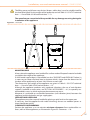
5.2POSITION OF THE APPLIANCE
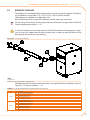
Lifting the appliance and placing it in position
Do not remove packaging during handling on the installation site.
Packing must only be removed upon final installation.
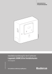
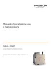
If the appliance has to be lifted, pass slings into the openings in the base supports and
use spreader bars to prevent the slings from damaging the casing during handling (see
Figure 5.1 Lift GS/WS → 27).
26
Installation, user and maintenance manual – GAHP-GS/WS
The lifting crane and all accessory devices (braces, cables, bars) must be suitable sized for
the load to be lifted. For the weight of the appliance, consult Table 3.1 GS HT/LT technical
data → 12 and Table 3.2 WS technical data → 13.
The manufacturer cannot be held responsible for any damage occurring during the
installation of the appliance.
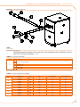
Figure 5.1 – Lift GS/WS
MOUNTING BASE
Always place the appliance on a levelled flat surface made of fireproof material and able
to support the weight of the appliance.
If a horizontal support base is unavailable (see also "SUPPORTS and LEVELLING" below), it
is necessary to create a flat level base in concrete which is larger than the dimensions of
the base of the appliance by at least 100-150 mm on each side.
The dimensions and weight of the appliance are given in Table 3.1 GS HT/LT technical
data → 12 and in Table 3.2 WS technical data → 13.
Although the appliance produces only moderate vibrations, the use of anti-vibration
supports (available as accessories, see SECTION 8 ACCESSORIES → 81) is especially recommended in cases in which resonance phenomena may occur.
Moreover, it is advisable to use flexible connections (anti-vibration joints) between the
appliance and the hydraulic and gas supply pipes.
SUPPORTS AND LEVELLING
The appliance must be correctly levelled by placing a spirit level on the upper part.
If necessary, level the appliance with metal shimming; do not use wooden spacers as
these deteriorate quickly.
CLEARANCES AND WARNINGS
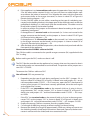
Position the appliance so as to maintain minimum clearances from combustible surfaces, walls or other appliances, as illustrated in Figure 5.2 Clearances → 28.
27
Minimum clearances are necessary in order to be able to carry out maintenance
operations.
The fumes outlet terminals must be installed in such a way that they do not allow the
fumes to collect or return to the circuit in the unit's installation area. The outlet terminal
must be constructed in conformity with established regulations.
Figure 5.2 – Clearances
Place the appliance preferably far from environments where silence is required, such as
bedrooms, meeting rooms, etc.
Evaluate the noise impact of the appliance in consideration of the installation site: avoid
installing the appliance in positions that could amplify its running noise (reverb effect).
5.3HYDRAULIC CONNECTIONS
General indications
• The hydraulic installation may be realized using pipes in stainless steel, black steel,
copper or crosslinked polyethylene for heating/cooling applications. All water
pipes and pipe connections must be properly insulated in compliance with current regulations to prevent heat losses and outer condensation.
• To prevent icing in the primary circuit during winter time, the appliance is provided
with antifreeze functions activating the water circulation pump of the primary circuit (if controlled by the appliance) and the burner of the appliance itself (when
necessary). It is therefore necessary to ensure a permanent supply of electricity
and gas to the appliance throughout the whole winter period. If it is not possible
to ensure a permanent supply of electricity and gas to the appliance, use glycol
antifreeze of the inhibited monoethylene type.
• If glycol antifreeze is to be used (see Paragraph 5.6 FILLING OF HYDRAULIC CIRCUIT → 34), DO NOT USE galvanised pipes, as they are potentially subject to corrosion phenomena in the presence of glycol.
• If using rigid pipes, use vibration damping couplings at the water and gas connections on the appliance's service plate to prevent vibration.
As other hydronic appliances, Robur heating and cooling systems operate with grid-water of good quality. In order to prevent any possible problem of operation or reliability
caused by filling or top-up water, please refer to codes and norms about water treatment
for thermo-hydraulic installations in civil or industrial applications. Parameters indicated
in Table 5.1 Chemical and physical parameters of water → 29 must be complied with.
28
Installation, user and maintenance manual – GAHP-GS/WS
Table 5.1 – Chemical and physical parameters of water
CHEMICAL AND PHYSICAL PARAMETERS OF WATER IN HEATING/COOLING SYSTEMS
PARAMETER
UNIT OF MEASUREMENT
pH
\
Chlorides
mg/l
°f
Total hardness (CaCO3)
°d
Iron
mg/kg
Copper
mg/kg
Aluminium
mg/l
Langelier’s index
\
HARMFUL SUBSTANCES
Free chlorine
mg/l
Fluorides
mg/l
Sulphides
1 with aluminium or light alloys radiators, pH must also be lower than 8 (in compliance with applicable rules)
2 value referred to the maximum water temperature of 80 °C
3 in compliance with applicable rules
ALLOWABLE RANGE
>7 (1)
< 125 (2)
< 15
< 8,4
< 0,5 (3)
< 0,1 (3)
<1
0-0,4
< 0,2 (3)
<1
ABSENT
Water quality can be measured through parameters like acidity, hardness, conductivity,
chlorides content, chlorine content, iron content and the like.
The presence of free chlorine in the water, in particular, can jeopardize parts of the installation and Robur units. Therefore, please make sure that free chlorine content and total
hardness are compliant with the allowable ranges reported in Table 5.1 Chemical and
physical parameters of water → 29.
The way the installation is operated can be the cause of possible degradation of water
quality.
Moreover, abnormally massive water top-up or reintegration can cause a drift of chemical
or physical above-mentioned parameters. Reintegration should not exceed 5% per year
of the total amount of water. It is advised to check regularly the water quality, especially
in case of automatic or periodic top-up.
In case water treatment is needed, this operation should be carried out by a professional
or competent person, following strictly the instructions by the manufacturer or supplier
of the chemical substances for the treatment, since dangers could arise for health, for the
environment and for Robur appliances.
Several products for water treatment are available on the market.
Robur does not perform detailed market surveys. Therefore Robur suggests to contact
Companies which are specialized in water treatments. They will be able to suggest the
best way how to proceed according to the type of installation.
In case washing of the pipes is needed, this operation should be carried out by a professional or competent person, following strictly the instructions by the manufacturer or
supplier of the chemical substances for the washing, avoiding the use of substances aggressive for stainless steel or containing/releasing free chlorine.
Please make sure the pipes are properly rinsed in order to remove any residue of chemical substances from the pipes.
Robur is not liable for ensuring that water quality is always compliant with what reported
in Table 5.1 Chemical and physical parameters of water → 29. Non-compliance with indications above may jeopardize the proper operation, integrity and reliability of Robur
appliances, invalidating the warranty.
For any further detail, please contact directly Robur S.p.A. (tel.+39 035.888.111).
The components below are always to be fitted in proximity to the appliance:
• FLEXIBLE JOINTS on water and gas connections of the appliance.
• PRESSURE GAGES on the inlet and outlet water pipes.
29
•
•
•
•
•
•
F LOW REGULATION VALVE on the water inlet pipe (only if the appliance is controlled by a CCP/DDC).
WATER FILTER installed on the water inlet pipe.
ISOLATION BALL VALVE on the water and gas pipes of the installation.
3 BAR SAFETY VALVE installed on the outlet water pipe.
PLANT EXPANSION TANK installed in the appliance outlet water pipe.
EXPANSION TANK for the individual appliance, installed on the water outlet pipe
(primary side). Provide a plant expansion tank in any case (secondary side), installed in the water outlet pipe.
The appliance is not equipped with an expansion tank; therefore it is necessary to install
a suitable expansion tank, sized for the maximum temperature range and maximum operating water pressure of the plant.
•
•
•
v ariable rate WATER CIRCULATION PUMP, FOR PLANT WITH A SINGLE APPLIANCE,
located on the water inlet pipe of the appliance, flowing towards the appliance.
variable rate WATER CIRCULATION PUMP, FOR PLANT WITH A SEVERAL APPLIANCES
(each appliance have is pump), flowing towards the appliance.
PLANT FILLING SYSTEM: if automatic filling systems are used, a seasonal check of
the percentage of monoethylene glycol in the plant is recommended.
For other components to be installed in the system, refer to "Design Manual". For further information or technical support in this regard, contact Robur S.p.A.'s Presales Office
(tel.+39 035.888.111) or visite site www.robur.it.
The operations necessary for the First Activation or Regulation of the appliance must be
carried out exclusively by an authorised Robur Technical Assistance Centre (TAC). These
operations are described in Section 7 INITIAL ACTIVATION AND MAINTENANCE → 73.
The products' guarantee is void if initial activation is not carried out by a Robur TAC.
5.4GAS SUPPLY
The installation of gas supply pipes must be compliant with current regulations and
norms.
The gas supply pressure must be in the range given in Table 5.2 Network gas
pressure → 31.
Supplying gas to the appliance at pressures higher than those indicated above can damage the gas valve, resulting in dangerous situations.
LPG systems must be equipped with a first stage pressure reducer close to the LPG storage tank, in order to reduce the gas pressure to 1,5 bar, and a second stage pressure
reducer, close to the unit, in order to reduce pression from 1,5 bar to the value in agreement with the gas network pressure of the country of installation (see Table 5.2 Network
gas pressure → 31).
Exemple for the Italian market: for the G30 gas, from 1,5 bar to 0,030 bar (30mbar); for the
G31 gas, from 1,5 bar to 0,037 bar (37mbar).
30
Installation, user and maintenance manual – GAHP-GS/WS
LPG may cause corrosion; piping and fitting materials must be resistant to this
corrosion.
Vertical gas pipes must be equipped with a siphon and provided with a drain for the condensate that may form inside the pipe during cold periods. It may also be necessary to
insulate the gas pipe to prevent the formation of excessive condensate.
In any case, provide an isolation valve (ball valve) on the gas supply line, to isolate the
appliance when required.
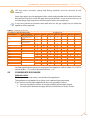
Table 5.2 – Network gas pressure
E3-GS; E3-WS; E3-A; GAHP-GS; GAHP-WS; GAHP-A
Product categories
Countries of destination
AL, BG, CY, CZ, DK, EE, FI, GR,
HR, IT, LT, MK, NO, RO, SE,
II2H3B/P
SI, SK, TR
AT, CH
AL, BG, CZ, ES, GB, HR, IE, IT,
LT, MK, PT, SI, SK, TR
II2H3P
RO
II2ELL3B/P
DE
II2Esi3P
FR
II2HS3B/P
HU
II2E3P
LU
II2L3B/P
NL
II2E3B/P
PL
II2ELwLs3B/P
II2ELwLs3P
I2E(R)B ; I3P
BE
I3P
IS
I2H
LV
I3B/P
MT
I3B
G20 [mbar]
G25 [mbar]
Gas supply pressure
G30 [mbar] G31 [mbar] G25.1 [mbar]
20
30
30
20
50
50
20
20
20
20
25
20
G2,350 [mbar]
20
20
13
13
37
20
25
50
30
25
20
20
20
20
G27 [mbar]
50
37
37
25
30
50
37
30
50
50
37
37
37
37
30
25
20
30
30
30
For data regarding hourly fuel consumption of the appliance, refer to Tables 3.1 GS HT/LT
technical data → 12 and 3.2 WS technical data → 13.
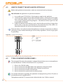
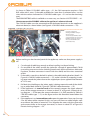
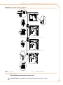
5.5CONDENSATE DISCHARGE
INDOORS UNITS
The fumes condensate outlet is on the left of the appliance.
The appliance is equipped with a siphon with a piece of pipe connected.
If you wish to use the pipe supplied with the unit, proceed as follows:
1. Connect the pipe to a plastic discharge manifold of the proper length.
2. The connection between the pipe and the manifold must remain visible.
31
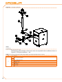
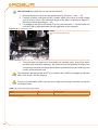
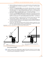
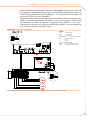
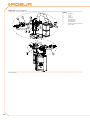
Figure 5.3 – Position of condensate discharge and manual reset fumes thermostat
LEGEND
DCondensate discharge
EHose connecting to condensate siphon
FFumes outlet
GFumes thermostat manual reset
Position of condensate discharge and manual reset fumes thermostat
The condensate discharge to the sewer must be:
• sized so as to discharge the maximum condensation flow (see Table 3.1 GS HT/LT
technical data → 12 and Table 3.2 WS technical data → 13 under the respective
heading);
• made of materials resistant to acidity with pH 3 to 5;
• sized to ensure a slope of 10 mm per metre of length; if this slope cannot be
achieved, a condensate pump must be installed near to the discharge;
• realized in such a way as to prevent icing of the condensate;
• mixed, for example, with domestic effluents (washing machine, dishwasher, etc.),
usually alkaline, acting as a buffer solution before discharging into the sewer.
Do not discharge the condensate into the guttering, since it may ice and corrode the
materials normally used for gutters.
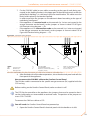
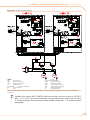
CHARGING THE SIPHON
To charge the siphon, proceed as follows:
1. Connect the condensate discharge pipe to a drain.
2. Remove the bottom left side panel to access the siphon.
3. If
no fumes exhaust equipment has been installed: pour 0.2 litres of water directly into the plastic pipe (detail F in Figure 5.3 Position of condensate discharge
and manual reset fumes thermostat → 32 and check that it is full. Then proceed to
point 6.
4. If
the fumes exhaust equipment has already been installed: remove the clamp
securing the plastic pipe E to the siphon (see Figure 5.3 Position of condensate
discharge and manual reset fumes thermostat → 32), disconnect the plastic pipe E
from the siphon and fill it with 0.2 litres of water.
32
Installation, user and maintenance manual – GAHP-GS/WS
5. R
econnect the plastic pipe E and secure it with its clamp.
6. Fit the bottom left side panel.
If the appliance is operated with the siphon empty, there is a risk of leaks of exhaust flue
gas.
OUTDOORS UNITS
The fumes condensate outlet is on the left of the appliance.
The distance L between the coupling and the base may not exceed 110 mm.
1. T he condensate discharge corrugated pipe, coming out from the side of the underbase left support, must be connected to a proper discharge header.
2. The connection between the pipe and the manifold must remain visible.
Figure 5.4 – Position of condensate discharge outdoors units
LEGEND
ACondensate discharge hose
DCorrugated hose
Position of condensate discharge outdoors units
The condensate discharge to the sewer must be:
• sized so as to discharge the maximum condensation flow (see Table 3.1 GS HT/LT
technical data → 12 and Table 3.2 WS technical data → 13 under the respective
heading);
• made of materials resistant to acidity with pH 3 to 5;
33
•
•
•
s ized to ensure a slope of 10 mm per metre of length; if this slope cannot be
achieved, a condensate pump must be installed near to the discharge;
realized in such a way as to prevent icing of the condensate;
mixed, for example, with domestic effluents (washing machine, dishwasher, etc.),
usually alkaline, acting as a buffer solution before discharging into the sewer.
Do not discharge the condensate into the guttering, since it may ice and corrode the
materials normally used for gutters.
5.6FILLING OF HYDRAULIC CIRCUIT
After having completed all hydraulic, gas and electrical connections, the installer can
proceed filling the hydraulic circuit, observing the following steps:
You will need: the appliance connected hydraulically and electrically.
COLD CIRCUIT GAHP-GS
1. Check that the system delivery and return are correctly connected to the appliance’s respective fittings (see Figure 3.1 Size → 15).
2. Activate the automatic air purging valves of the plant and open all thermostatic
valves.
3. Fill the hydraulic circuit to at least the minimum amount and add inhibited monoethylene glycol to a volume percentage of 25% (obligatory minimum required
for correct system operation) or greater depending on the minimum winter temperature in the installation area (see Table 5.3 Technical data for filling the hydraulic
circuit → 36). Robur recommends using inhibited corrosion resistant monoethylene glycol.
4. Check the filter on the return pipe for impurities; clean it if necessary.
5. Check that the siphon on the drainage condenses has been filled with water as
indicated in the relative paragraph.
6. Bring the plant to the correct pressure, making sure that the water pressure is not
less than 1 bar and not over 2 bar, and run the circulation pump for at least 30 minutes. Check the water filter again and clean it if necessary.
The technical data (Tables 3.1 GS HT/LT technical data → 12 and 3.2 WS technical data → 13) regarding the cold circuit refer to water with 25% glycol content, so that no
correction factor need to be applied to Table 5.3 Technical data for filling the hydraulic
circuit → 36.
To facilitate the operation of bleeding air from the hydraulic circuit, the appliance is
equipped with an additional manual air bleeding valve.
COLD CIRCUIT GAHP-WS
1. Check that the system delivery and return are correctly connected to the appliance’s respective fittings (see Figure 3.1 Size → 15).
2. Activate the automatic air purging valves of the plant and open all thermostatic
valves.
34
Installation, user and maintenance manual – GAHP-GS/WS
3. F ill the hydraulic circuit to at least the minimum amount and add inhibited monoethylene glycol to a volume percentage in proportion to the minimum winter
temperature in the installation area (see Table 5.3 Technical data for filling the hydraulic circuit → 36). Robur recommends using inhibited corrosion resistant monoethylene glycol.
Glycol antifreeze may not be used on condition that the antifreeze function, which
runs the circulation pumps, is activated at the CCI/DDC. This function requires the
appliance to be ALWAYS powered up (electricity and gas) and power failures excluded, otherwise the manufacturer declines all contractual and extra-contractual liability for consequent damage.
4. C
heck the filter on the return pipe for impurities; clean it if necessary.
5. Bring the plant to the correct pressure, making sure that the water pressure is not
less than 1 bar and not over 2 bar, and run the circulation pump for at least 30 minutes. Check the water filter again and clean it if necessary.
The technical data (Tables 3.1 GS HT/LT technical data → 12 and 3.2 WS technical data → 13) regarding the cold circuit refer to water with 25% glycol content, so that no
correction factor need to be applied to Table 5.3 Technical data for filling the hydraulic
circuit → 36.
To facilitate the operation of bleeding air from the hydraulic circuit, the appliance is
equipped with an additional manual air bleeding valve.
HOT CIRCUIT (Heating, sanitary hot water)
1. Check that the system delivery and return are correctly connected to the appliance’s respective fittings (see Figure 3.1 Size → 15).
2. Activate the automatic air purging valves of the plant and open all thermostatic
valves.
3. Fill the hydraulic circuit to at least the minimum amount and add inhibited monoethylene glycol to a volume percentage in proportion to the minimum winter
temperature in the installation area (see Table 5.3 Technical data for filling the hydraulic circuit → 36). Robur recommends using inhibited corrosion resistant monoethylene glycol.
Glycol antifreeze may not be used on condition that the antifreeze function, which
runs the circulation pumps and the appliance, is activated at the CCI/DDC. This
function requires the appliance to be ALWAYS powered up (electricity and gas) and
power failures excluded, otherwise the manufacturer declines all contractual
and extra-contractual liability for consequent damage.
4. C
heck the filter on the return pipe for impurities; clean it if necessary.
5. Check that the siphon on the condensate discharge has been filled with water as
indicated in Paragraph 5.5 CONDENSATE DISCHARGE → 31 under "Loading the
siphon".
6. Bring the plant to the correct pressure, making sure that the pressure of the water
in the plant is not less than 1 bar and not over 2 bar, and run the circulation pump
for at least 30 minutes. Check the water filter again and clean it if necessary.
35
To facilitate the operation of bleeding air from the hydraulic circuit, the appliance is
equipped with an additional manual air bleeding valve.
Use of glycol antifreeze
Glycols, normally used to lower the freezing point of water, are substances in an intermediate state of oxidation which, in the presence of oxidising agents such as oxygen,
are transformed into corresponding acids. This transformation into acids increases the
corrosive nature of the fluid contained in the circuit. For this reason, mixtures that are
commercially available almost always contain inhibiting substances that are able to control the pH of the solution. A condition necessary for the oxidation and degradation of
glycol is the presence of an oxidising agent such as oxygen. In closed circuits in which no
replenishment of water (and therefore of oxygen) occurs over time, once the oxygen initially present has reacted, the degenerative phenomenon of glycol is hugely inhibited.
Most circuits, however, are of the non-sealed type, and therefore receive a more or less
continuous supply of oxygen.
Therefore it is essential, whatever type of glycol is in question, to verify that it is adequately inhibited and that the necessary checks are regularly performed during its entire
period of use.
Antifreeze liquids for cars, which do not contain inhibiting components other than ethylene glycol, are not recommended for cooling and heating plants.
The manufacturer does not accept any contractual or extra-contractual liability for
damages caused by the use or disposal of glycol antifreeze.
It is equally important to recall that the use of monoethylene glycol modifies the thermophysical characteristics of the water in the plant, and in particular its density, viscosity
and average specific heat. Always check the date of expiry and/or degradation of the
product with the supplier.
The technical data (Tables 3.1 GS HT/LT technical data → 12 and 3.2 WS technical data → 13) regarding the hot circuit refer to non-glycolised water, so that the correction
factors of Table 5.3 Technical data for filling the hydraulic circuit → 36 must be applied
to obtain the consequent increased load drop of the system and penalisation of unit efficiency in relation to the percentage of monoethylene glycol used.
Table 5.3 Technical data for filling the hydraulic circuit → 36 should be taken into account
for the sizing of the pipes and the circulation pump (for calculation of internal pressure
drops of the appliance, refer to Tables 3.1 GS HT/LT technical data → 12 and 3.2 WS technical data → 13).
Nevertheless, it is advisable to consult the technical specifications of the monoethylene
glycol used. If automatic loading systems are used, a seasonal check of the quantity of
glycol present in the plant is also necessary.
Table 5.3 – Technical data for filling the hydraulic circuit
% of MONOETHYLENE GLYCOL
WATER-GLYCOL MIXTURE FREEZING TEMPERATURE
PERCENTAGE OF INCREASE IN PRESSURE DROPS
LOSS OF EFFICIENCY OF UNIT
10
-3°C
---
15
-5°C
6%
0,5%
20
-8°C
8%
1%
25
-12°C
10%
2%
30
-15°C
12%
2,5%
35
-20°C
14%
3%
40
-25°C
16%
4%
If the percentage of glycol is ≥ 30% (for ethylene glycol) or ≥ 20% (for propylene glycol):
•
36
then parameter 182 in menu 4 must be set to “1” (at the installer’s care).
Installation, user and maintenance manual – GAHP-GS/WS
5.7EXHAUST FLUE GAS
The appliance is homologated for configuration as a type C and B installation. The following installations are possible: C13, C33, C43, C53, C63, C83, B23P and B33.
The appliance is supplied in configuration C63.
We list below the various types of installation and the necessary accessories.
For the sizing of the fumes exhaust pipe and the combustion air pipe, refer to Table 5.9
Fumes temperature and flow → 41.
In case of installation of more than one unit GS/WS connected to one flue pipe, it’s necessary to insert one clapet valve for each installed unit, in order to avoid the reflux of the
flue through the unit that is not working.
Figure 5.5 – C13 type installation
LEGEND
See table below
Wall mounted co-axial outlet DN80/125 or DN60/100
The following table indicates which accessories are required for the installation shown in
Figure 5.5 C13 type installation → 37
Table 5.4 – C13 type installation: wall mounted co-axial terminal
DN
80/125
60/100
Ref.
A
B
E
E
F
F
A
B
E
E
F
F
Description
DN80/125 2xDN80 double fitting
Co-axial wall terminal DN80/125
Co-axial pipe 80/125 L=1 m
Co-axial pipe 80/125 L=2 m
Co-axial bend 90° 80/125
Co-axial bend 45° 80/125
DN60/100 2xDN80 double fitting
Co-axial wall terminal DN60/100
Co-axial pipe 60/100 L=1 m
Co-axial pipe 60/100 L=2 m
Co-axial bend 90° 60/100
Co-axial bend 45° 60/100
37
Figure 5.6 – C33 type installation
LEGEND
See table below
Roof mounted co-axial outlet DN80/125 or DN60/100
The following table indicates which accessories are required for the installation shown in
Figure 5.6 C33 type installation → 38.
Table 5.5 – C33 type installation: roof mounted co-axial terminal
DN
80/125
60/100
38
Ref.
A
B
C
D
E
E
F
F
A
B
C
D
E
E
F
F
Description
DN80/125 2xDN80 double fitting
Co-axial roof terminal 80/125
Tile adaptor for sloped roof
Tile adaptor for flat roof
Co-axial roof pipe 80/125 L=1 m
Co-axial roof pipe 80/125 L=2 m
Co-axial bend 90° 80/125
Co-axial bend 45° 80/125
DN60/100 2xDN80 double fitting
Co-axial roof terminal 60/100
Tile adaptor for sloped roof
Tile adaptor for flat roof
Co-axial roof pipe 60/100 L=1 m
Co-axial roof pipe 60/100 L=2 m
Co-axial bend 90° 60/100
Co-axial bend 45° 60/100
Installation, user and maintenance manual – GAHP-GS/WS
Figure 5.7 – C43 type installation
LEGEND
See table below
Fumes/combustion air collective pipes
The following table indicates which accessories are required for the installation shown in
Figure5.7 C43 type installation → 39
Table 5.6 – C43 installation.
DN
80/125
60/100
Ref.
A
B
C
D
E
E
F
F
G
G
H
L
A
B
C
D
E
E
F
F
G
G
H
L
Description
DN80/125 2xDN80 double fitting
Wall duct DN 80/125
Flue mount kit DN80
Flue cover DN80 with terminal
Co-axial bend 90° 80/125
Co-axial bend 45° 80/125
Co-axial pipe DN80/125 L=1 m
Co-axial pipe DN80/125 L=2 m
Pipe DN 80 L=1 m
Pipe DN 80 L=2 m
Bend 90° DN80
Bend 45° DN80
DN60/100 2xDN80 double fitting
Wall duct DN 60/100
Flue mount kit DN60
Flue cover DN60 with terminal
Co-axial bend 90° DN60/100
Co-axial bend 45° DN60/100
Co-axial pipe DN60/100 L=1 m
Co-axial pipe DN60/100 L=2 m
Pipe DN 60 L=1 m
Pipe DN 60 L=2 m
Bend 90° DN60
Bend 45° DN60
39
Figure 5.8 – C53 type installation
LEGEND
See table below
Roof mounted flue, wall mounted air intake
The following table indicates which accessories are required for the installation shown in
Figure 5.8 C53 type installation → 40
Table 5.7 – C53 type installation: Roof mounted flue, wall mounted combustion air intake
DN
80
40
Ref.
A
B
C
D
E
F
F
G
H
Description
Double intake/exhaust kit DN80
Flue cover DN80 with terminal
Flue mount kit DN80
Pipe DN80 L = 1 m
Pipe DN80 L = 2 m
Bend 90° DN80
Bend 45° DN80
Installation, user and maintenance manual – GAHP-GS/WS
Figure 5.9 – C53 type installation
LEGEND
See table below
Double wall mounted exhaust
The following table indicates which accessories are required for the installation shown in
Figure 5.9 C53 type installation → 41
Table 5.8 – C53 type installation
DN
Ref Description
B
C
Wall mounted terminal kit DN80
D
80
F
Pipe DN80 L=1 m
F
Pipe DN80 L=2 m
G
Bend 90° DN80
H
Bend 45° DN80
Double wall mounted exhaust
Table 5.9 – Fumes temperature and flow
Gas type
G20
G25
G25.1
G27
G2.350
G30
G31
Thermal capacity
Nominal
Minimum
Nominal
Minimum
Nominal
Minimum
Nominal
Minimum
Nominal
Minimum
Nominal
Minimum
Nominal
Minimum
CO2 (%)
9,10
8,90
9,10
8,90
10,10
9,60
9,0
8,5
9,00
8,70
10,40
10,10
9,10
8,90
TF (C°)
65
46
63,6
45,7
65
46
64
46
62,7
46,8
65
46
65
46
Fumes flow (kg/h)
42
21
42
21
45
23
42
21
42
22
43
22
48
24
Prevalenza residua (Pa)
80
80
80
80
80
80
80
80
80
80
80
80
80
80
41
5.8PROGRAMMING OF HYDRAULIC PARAMETERS
The operations described in this paragraph are necessary only if the appliance is not connected to a DDC or to a CCP.
If the appliance is connected to a CCP/DDC, follow the instructions given in the CCP/DDC
manuals exclusively.
This paragraph explains how to set the hydraulic parameters on the electronic board
of the appliance. Users not familiar with the basic procedures for the use of the board
should refer to Paragraph 4.2 ON-BOARD ELECTRONICS → 19.
To configure the appliance, access menu 3 of the electronic board.
With regard to the hydraulic configuration, six parameters may be set: select the letter E
to exit to the previous menu.
Table 5.10 – Parameters for hydraulic configuration
HYDRAULIC PARAMETER
Select cold water thermostating
Cold water set-point
Cold water temperature differential
Hot water thermostat control selection
Hot water setpoint
Hot water temperature differential
(EXIT MENU)
Menu 3 parameters.
THE DISPLAY SHOWS
3. 73
3. 75
3. 76
3.160
3.161
3.162
3. E
Description of parameters:
• Water thermostat control, parameters 73 and 160. This parameter takes two values: "0" and "1". Value "0" indicates that the appliance's "activation/deactivation"
temperature is to be read by the water probe at the appliance’s INTAKE. Value "1"
indicates that the appliance’s "activation/deactivation" temperature is to be read
by the water probe at the appliance’s OUTLET.
• Water set-point, parameters 75 and 161: these parameters set the water temperature that, when reached, causes the appliance to be deactivated (when the power
modulation is not active - parameter 181).
• Water differential, parameters 76 and 162: these parameters represent an interval
in degrees that, when added to the set-point, defines the temperature at which the
appliance is reactivated. These parameters are used only if the power modulation
is NOT active (parameter 181).
The appliance functions by heating/cooling the water until it reaches the set-point temperature. At this point, if the power modulation is not active (parameter 181), it switches
off. The temperature of the water goes down again until it reaches the temperature corresponding to "set-point + differential"; when this is reached the appliance switches on
again.
Example (heating):
Thermostating: reading from inlet sensor.
Parameter 181: 0 (power modulation NOT active)
Set-point: +40.0°C
Differential: - 2.0° C
• The appliance is functioning: the water in the plant heats up until it reaches the
set-point temperature = +40°C.
42
Installation, user and maintenance manual – GAHP-GS/WS
•
T he appliance switches off: the water in the plant, returning from use, becomes
progressively cooler, until it reaches a temperature of 38°C = 40°C - 2°.
• The appliance switches on again, and the plant water heats up again.
• The cycle is repeated.
The following procedure illustrates in detail how to configure the parameters on the electronic board inside the appliance.
If the procedures for how to access the knob and menus are not familiar, see paragraphs
"Display and knob" and "How to access the menus" and following.
To set the parameters of menu 3:
You will need: the appliance on and access to the electrical panel, see "Display and
knob".
Access menu 3. The display shows the first parameter of the menu, number 73.
1. Turn the knob clockwise to scroll through the parameters: 3.73, 3.75, 3.76, 3.160,
3.161, 3.162; lastly the letter E is shown.
2. Press the knob when a parameter is displayed to select it, or when E is displayed to
exit the menu.
3. For example, to set parameter 161 (hot water set-point), proceed as follows:
· Select the parameter: turn the knob until the display shows 3.161;
· Press the knob to access the value of the parameter; the display shows the previously set value, which flashes, for example 40.0 °C;
· Turn the knob to modify the value of the parameter;
· Press the knob to confirm the value selected; the display shows the current parameter again, 3.161. The new value for this parameter has been set.
4. If other parameters are to be modified, proceed as described previously, and then
exit from the menu by pressing the knob on the letter E.
To exit the menu, turn the knob clockwise until E is displayed, then press it to confirm. For
details regarding the codes displayed by the appliance during operation, see Paragraph
9.1 OVERVIEW AND OPERATING CODES/TROUBLESHOOTING → 82.
5.9SAFETY VALVE DISCHARGE ROUTING
Standard EN378-3 requires that potential leaks of refrigerant be discharged outside the
machine room.
To meet this requirement, the appliance has an outlet on its top panel (detail Q of Figure
3.1 Size → 15) to which a pipe can be fitted to route the refrigerant vented by the safety
valve on the sealed circuit out of the machine room.
DO NOT fit any check equipment (valve, etc.) between outlet Q (Figure 3.1 Size → 15) and
the external discharge of the evacuation pipe. The manufacturer does not accept any
contractual or extra-contractual liability for any damage caused by improper use of the
said pipe.
The missing right installation of the canalization of the security valve might cause dangerous situations inside the installation room. The unit can be switched-on only if the
right canalitation is installed, as indicated in the following.
Install the pipe as instructed below.
43
You will need: the appliance in its permanent location.
1. R
emove the plastic cap on the top panel (detail Q of Figure 3.1 Size → 15).
2. Connect a carbon steel pipe to the Q outlet, which must have an initial straight
tract of at least 30 cm. The maximum length of the pipe is indicated in Table 5.11
Maximum coolant pipe length → 44).
3. Fix the pipe to the nut on the outlet (5.10 Over-pressure valve → 44) and make sure
to fit the Teflon gasket provided with the appliance for this purpose.
Figure 5.10 – Over-pressure valve
LEGEND
Detail of the refrigerant flexible ducting
pipe
Position of the valve
4. T he evacuation terminal must be outside the machine room, away from doors,
windows and ventilation openings; the terminal must be located at a height such
as to prevent any leaks of refrigerant fluid being inhaled by persons walking in the
vicinity of the terminal itself.
The refrigerant discharge pipe MUST be in carbon steel. NEVER use copper or derivate
alloys such as brass for this purpose.
The missing canalitation of the security valve might cause danger conditions inside the
installation room.
Table 5.11 – Maximum coolant pipe length
Diameter
1" 1/4
2"
Maximum coolant pipe length
44
DN
32
52
Maximum length (m)
30
60
Installation, user and maintenance manual – GAHP-GS/WS
6ELECTRICAL INSTALLATION
This section illustrates the operations to perform for the correct electrical installation of
the appliance, and contains electrical diagrams that may be of use in the event of maintenance operations.
Installation of the appliance may only be carried out by firms that are qualified in accordance with current legislation in the country of installation, i.e. by professionally qualified
personnel.
Before proceeding with operations to create the electrical plant of the appliance, the
professionally qualified personnel concerned are advised to read Paragraph 3.1 GENERAL
INFORMATION → 8: it provides important information regarding installation safety and
references to current norms.
Installation that is incorrect or that does not comply with current legislation may cause
damage to people, animals or things; Robur S.p.A. is not responsible for any damage
caused by installation that is incorrect or that does not comply with current legislation.
Figure 6.1 Electronic board S61 → 46 and Table 6.1 S61 electronic controller + Mod10
legend → 46 provide details of input and ouput of the S61 electronic board. The auxiliary
electronic card Mod10 is shown in detail in Figure 6.2 Mod10 controller → 47.
The appliance and the system can be controlled and regulated in one of the following
ways depending on the type of installation and control system selected:
• TYPE
A: controlled by CCP (see Figure 6.4 Comfort Control Panel e Accessory → 48,
detail CCP).
• TYPE
B: controlled by DDC (see Figure 6.3 CCI/DDC → 47).
• TYPE
C: controlled by consent switch (e.g. on-off switch, ambient thermostat, timer, etc.).
In Paragraph 6.1 ELECTRICAL DIAGRAM OF THE APPLIANCE → 49 may be found the Electrical diagrams of the appliance.
45
Figure 6.1 – Electronic board S61
LEGEND
See table below
SCH S61
Table 6.1 – S61 electronic controller + Mod10 legend
CODE
SCH1
SCH3
A1, A2
ENC
F1
F2
F3
F4
FAN (BK, WH, BR)
FL
FS5 (24V AC)
IGN.BOX (L, N)
J1
J10
J82
JP10
JP12
JTAG
MAIN 230V (L,N)
N.O. contact
P7 (R, W, Y, o)
P8 (GND, L, H)
PUMP 230V (L,N)
SPI
SRT1
SRT2
TA
TA1
TA2
TCN
TF
46
DESCRIPTION
Electronic board S61
Mod10 electronic controller (see figure for further details)
Auxiliary inputs
Knob
Fuse T 2A
Fuse F 10A
Fuse T 2A
Fuse T 3.15A
Cooling fan output
Flow switch input
Controller power 24-0-24 Vac
Flame controller power 230 V AC
CAN BUS jumper
Jumper N.O. contact
W10 board connector (on Mod10)
6-pole flame controller connector
Fumes sensor or generator fin sensor input
S61 controller programming connector
S61 controller power 230 V AC
Pump contact, N.O.
Consent inputs
CAN BUS connector
Hydraulic pump power output
Communication port with Mod10 controller
Hydraulic pump rotation sensor input
Hot water flowmeter input
Ambient temperature probe input
Hot water delivery temperature probe input
Hot water return temperature probe input
Combustive air temperature probe input
Exhausted gas thermostat input
Installation, user and maintenance manual – GAHP-GS/WS
CODE
TG
THMF
THRF
TL
DESCRIPTION
Generator temperature probe input
Cold water delivery temperature probe input
Cold water return temperature probe input
Generator limit thermostat input
Figure 6.2 – Mod10 controller
LEGEND
HFLOWNot used
CFLOWCondensation water sensor control
J51SPI connector
HPMPPrimary circuit hot water pump control
output (0-10 V) [A/GS/WS]
CPMPCold side water pump control output
[GS/WS]
NC1-C1Status indication of locking warnig/error
CN5Blower control
J82W10 auxiliary controller connector
J83W10 cable shielding connection W10
CN1Inputs 0-10V (not used)
Mod10 controller
Figure 6.3 – CCI/DDC
47
Figure 6.4 – Comfort Control Panel e Accessory
LEGEND
CCPComfort Control Panel
Components componing the CCP
AVS37Comfort Control Siemens
RVS61System controller and set-point
CCIComfort Control Interface
PLCProgrammable Logic Control
AVS75Expansion
48
Optional components to predict
QAA55Base room unit
QAA75Room unit
QAA78Radio room unit
ASV71Antenna
AVS13Transmitter
QAC34External temperature probe
LPS Central communications for remote control
LEGEND
SCH1S61 circuit board
SCH2W10 circuit board
SCH3Mod10 circuit board
TERAppliance power terminal block
CNTBOXFlame controller
PWRTRBoard transformer
BLWBlower
PMPHydraulic pump
IGNTRIgnition transformer
IGNIgnition electrodes
FLSFlame sensor
LSGas valve ON indicator lamp
GVGas solenoid valve
THMFCold water delivery temperature sensor
THRFCold water return temperature sensor
TMIXCombustion air temperature sensor
TAAmbient air temperature sensor
TGGenerator temperature sensor
THMCHot water delivery temperature sensor
THRCHot water return temperature sensor
REEDHydraulic pump rotation sensor
TF Fumes temperature sensor or generator fin sensor
TCManual fumes thermostat
TLGenerator limit thermostat
FMHot side flowmeter
FLRenewable source water flow switch
CWSCondensation water sensor
MATerminal block
TKCondensate discharge heating element thermostat
FSCondensate hose heating element
Installation, user and maintenance manual – GAHP-GS/WS
6.1ELECTRICAL DIAGRAM OF THE APPLIANCE
Figure 6.5 – Appliance internal wiring diagram
49
6.2HOW TO CONNECT THE APPLIANCE ELECTRICALLY
Before making electrical connections, make sure not to work on live elements.
You will need: the appliance in its permanent location.
1. U
se a cable type FG7(O)R 3Gx1.5 for the power supply to the appliance.
2. Connect power supply with the cable indicated at point 1, fitting close to the appliance a two-pole isolator switch with 3 mm distance between contacts (see detail
«GS» in Figure 6.6 Electrical wiring diagram → 50) and two 5A fuses type T or a 10A
magnetothermic breaker.
3. Prepare the electrical connection in such a way that the ground wire is longer than
the live wires. In this way it will be the last wire to be torn away if the cable is accidentally pulled off; this will ensure the ground connection.
Electrical safety is ensured only when the appliance is correctly connected to an efficient
grounding system, realized according to current safety regulations. Do not use gas pipes
as grounding.
Figure 6.6 – Electrical wiring diagram
LEGEND
TERterminal board
Lphase
Nneutral
Components NOT SUPPLIED
GSgeneral switch
Example of connection of appliance to 230 V 1 N - 50 Hz electricity supply
6.3TYPE A (COMFORT CONTROL PANEL)
This paragraph illustrates the operations to be performed when one or more appliances
are connected to a Comfort Control Panel (CCP). In particular:
1.
2.
3.
4.
5.
hat is the CAN BUS cable.
W
How to connect the CAN BUS cable to the appliance's electronic board
How to connect the CAN BUS cable to the Comfort Control Panel
How to connect the Comfort Control Panel
How to connect the system water circulation pumps
For specific information regarding the operation and programming of the CCP, refer to
the specific manuals supplied with it.
The appliance and the CCP communicate with each other via a CAN bus network.
50
Installation, user and maintenance manual – GAHP-GS/WS
The CAN bus network is characterized by a series of elements (appliances or CCPs) called
nodes, connected to each other by a three-wire cable. The nodes are of two types: terminal nodes and intermediate nodes.
• Terminal nodes are appliances or CCPs that are connected to one other element
only.
• Intermediate nodes are appliances or controllers which are connected to two other
elements.
The diagram in Figure 6.7 Example of CAN BUS → 51 gives an example of a CAN BUS
network: 3 appliances are connected to each other and to 1 CCP. Appliance D and the
CCP (A) are terminal nodes, while appliances C and B are intermediate nodes as they are
connected to 2 elements.
One CCP can control up to 3 appliances of the same type.
Figure 6.7 – Example of CAN BUS
LEGEND
AController
B-C-DAppliance
1-4Terminal nodes
2-3Intermediate nodes
Terminal nodes and intermediate nodes
What is the CAN BUS cable
The cable to be used must be suitable for CAN BUS applications.
The following table gives details of some types of CAN BUS cables, grouped according to
the maximum distance covered by each single type.
Table 6.2 – CAN BUS cables type
CABLE NAME
SIGNAL / COLOR
Robur
ROBUR NETBUS
H= BLACK
L= WHITE
Honeywell SDS 1620
BELDEN 3086A
H= BLACK
L= WHITE
TURCK type 530
DeviceNet Mid Cable
TURCK type 5711
H= BLUE
L= WHITE
Honeywell SDS 2022
TURCK type 531
H= BLACK
L= WHITE
Example types of cables used to connect the CAN network.
MAX LENGTH
GND= BROWN
450 m
GND= BROWN
450 m
GND= BLACK
450 m
GND= BROWN
200 m
Note
Ordering Code O-CVO008
In all cases the fourth conductor should not be used
For total distances lower than 200 m and networks with a maximum of 4 nodes (example:
up to 3 GAHP + 1 controller) a simple shielded cable 3x0.75 mm may be used.
51
As shown in Table 6.2 CAN BUS cables type → 51, the CAN connection requires a CAN
BUS cable with 3 cores. If the cable available has more than 3 coloured wires, use the
wires with the colours indicated in 6.2 CAN BUS cables type → 51 and cut the remaining
ones.
The ROBUR NETBUS cable is available as an accessory, see Section 8 ACCESSORIES → 81.
How to connect the CAN BUS cable to the appliance's electronic board
The CAN BUS cable must be connected to the dedicated terminals on the appliance’s
electronic board, as shown below (see Figure 6.8 CAN BUS cable connection → 52).
Figure 6.8 – CAN BUS cable connection
LEGEND
Aprotective isolating tape
Bshielding of CAN BUS cable (prewired to last unit)
Ccable bracket (the CAN BUS cables
of an intermediate node are present)
DCAN BUS/circuit board connector
Ewires (6) of the CAN BUS cable
(intermediate node)
B
A
D
C
E
A
Example of a single CAN bus cable connected to the board
Before working on the electrical panel of the appliance, make sure that power supply is
off.
1. C
ut a length of cable long enough to allow installing it without kinking.
2. On one end of the cable, remove the jacket for a length of approximately 70-80
mm, taking care not to cut the shielding (metal mesh and/or aluminium sheet and,
if present, the bare connector in touch with the shield) and the wires contained
within.
3. If the cable is too thin to be held in place in the cable holding bracket (detail C in
Figure 6.8 CAN BUS cable connection → 52), make it thicker by wrapping insulating tape around the jacket close to the stripped part (to an approximate diameter
of 12-13 mm).
4. Pull back the shielding on the jacket; apply isolating tape to the end of the shielding as pulled back (detail A, Figure 6.8 CAN BUS cable connection → 52).
5. If the appliance is a terminal node of the network connect the three coloured
wires to the orange connector as shown in detail "A" of Figure 6.9 Electrical wiring diagram → 53. Respect the correct indications L, H, GND provided in Table 6.2
CAN BUS cables type → 51, on the figure and on the electronic board below the
connector.
6. If the appliance is an intermediate node repeat the operations from step 2 to step
5 for the other cables required (in this way you will have two cable lengths each
one without the jacket on one end). Twist together the cores with the same color
and connect them to the orange connector, as shown in detail "B" of Figure 6.9
Electrical wiring diagram → 53.
52
Installation, user and maintenance manual – GAHP-GS/WS
7. F ix the CAN BUS cable (or two cables, according to the type of node being connected) to the holding bracket in the upper part of the electrical panel so that the
pulled-back shielding is in solid touch with the metal bracket. The cables must be
firmly held in place by the bracket if pulled.
In order to position the jumpers on the electronic board according to the type of
node being configured:
• If the appliance is a terminal node on the network (i.e. 3 wires are inserted in the
orange connector on the board): set the jumpers as shown in detail "A" of Figure
6.9 Electrical wiring diagram → 53:
• If the appliance is an intermediate node on the network (i.e. 6 wires are inserted
in the orange connector on the board); set the jumpers as shown in detail "B" of
Figure 6.9 Electrical wiring diagram → 53:
Figure 6.9 – Electrical wiring diagram
LEGEND
SCHelectronic board
GNDCommon data
LData signal LOW
HData signal HIGH
J1Jumper CAN-BUS in board
ADetail case "terminal node" (3 wires;
J1=jumper "closed")
BDetail case "intermediate node" (6
wires; J1=jumper "open")
P8Port can/connector
Connection cable CAN BUS to electronic board: detail A case "terminal node", detail B case "intermediate node"
8. A
fter finished with all the above operations, close the electrical panel and refit the
front panel of the appliance.
How to connect the CAN BUS cable to the Comfort Control Panel
The CAN bus cable is connected to the specific orange connector (P8) supplied with the
CCP in a bag.
Before working on the Comfort Control Panel, make sure that it is off.
The CCP, like the controller on the appliance, has jumpers that must be moved so that it
can be configured as an intermediate or terminal node. The position of the jumpers on
a new CCP is CLOSED.
To connect the CAN bus cable to a CCP:
You will need: the Comfort Control Panel not powered up.
1. Open the Comfort Control Panel’s electrical panel with the handle on its left.
53
2. D
epending on the type of node being configured, set the CCI’s jumpers J21 as
shown in detail "A" or detail "B" in Figure 6.11 Connection of CCI to CAN-BUS network → 55. If necessary, open the CCI’s back panel (4 screws); after jumpers J21
have been correctly positioned, close the cover again and retighten the 4 bolts.
3. Cut a length of cable long enough to allow installing it without kinking.
4. Remove the sheath for a length of approximately 70-80 mm, taking care not to cut
the shielding (metallic shield and/or aluminium sheet and, if present, the bare connector in contact with the shield) and wires contained inside.
5. Roll the shielding and connect it to a 4-mm eyelet terminal, as illustrated in Figure
6.10 Connection from CAN BUS to connector P8 → 55, details C and D. Now proceed as follows:
6. If the CCP is a terminal node of the network connect the three coloured wires to
the orange connector "P8", as shown in detail "A" of Figure 6.11 Connection of CCI
to CAN-BUS network → 55. Observe the terminal markings L, H, GND (on the CCI's
board at the base of the socket "P8") which are given both in Table 6.2 CAN BUS
cables type → 51 and in the example.
7. If the CCP is an intermediate node repeat the operations from step 2 to step 4 for
the other length of CAN bus cable required. Connect the six coloured wires to the
orange connector "P8", following the instruction provided in detail "B" of Figure
6.11 Connection of CCI to CAN-BUS network → 55. Observe the terminal markings
L, H, GND (on the CCI's board at the base of the socket "P8") which are given both
in Table 6.2 CAN BUS cables type → 51 and in the example.
8. Insert the orange connector "P8" with the wires first into the opening prepared in
the cover of the CCI, and then into the appropriate socket on the CCI itself, making
sure it is correctly inserted.
9. Use the rear cover bolts located near the CAN BUS socket to secure the 4-mm
eyelet (or 2 eyelets) (detail D, Figure 6.10 Connection from CAN BUS to connector
P8 → 55). The cable should be secured against pulling out.
The CCI has jumpers J21: the position of the jumpers, depends if the CCI is an intermediate or terminal node, must be as shown in Figure 6.11 Connection of CCI to CAN-BUS
network → 55.
The CCI is equipped with a backup battery which retains the memory settings in case
of power failure. The backup battery lasts approximately 7 years, after which time it
must be replaced by an authorised Robur Technical Assistance Centre.
54
Installation, user and maintenance manual – GAHP-GS/WS
Figure 6.10 – Connection from CAN BUS to connector P8
LEGEND
AInsulating tape to protect board/shield
BCAN BUS cable wires
CCAN bus cable shield
Dterminal and screw for fixing
Connection detail of cable CAN BUS.
Figure 6.11 – Connection of CCI to CAN-BUS network
LEGEND
CCIComfort Control Interface
P8Orange connector
J21Jumpers CAN-BUS on CCI board
Adetail of "terminal node" case (3 wires; J21=jumper "closed")
BDetail of "intermediate node" case (6 wires; J21=jumper "open")
H,L,GND Data signal wires
Jumpers J21 closed
The following wiring diagrams show the connection of the CCI to 1 appliance (Figure 6.12
Connection of CCI to 1 appliance → 56) and 3 appliances (Figure 6.13 Connection of CCI
to 3 appliances → 57) respectively.
55
Figure 6.12 – Connection of CCI to 1 appliance
LEGEND
SCHS61 controller
Connection of CCI to 1 appliance
56
CCIComfort Control Interface
Installation, user and maintenance manual – GAHP-GS/WS
Figure 6.13 – Connection of CCI to 3 appliances
LEGEND
SCHS61 controller
CCIComfort Control Interface
Connection of CCI to 3 appliances
How to connect the Comfort Control Panel
You will need: the appliance disconnected from the electricity supply
57
1. T he Comfort Control Panel’s power cord must be type tipo FG7 3Gx2.5mm2. the
power supply is 230V AC 1N 50Hz.
2. Cut a suitable length of cable.
3. The cable must be connected to the terminal block on the bottom right of the
Comfort Control Panel. First make a hole in the electrical cabinet near to the terminal block and pass the cable through it.
4. Connect the cable to the terminal block as given in Figure 6.6 Electrical wiring diagram → 50 and fit a 10 A thermal cut out upstream of the Comfort Control Panel.
How to connect the system water circulation pumps
Before making the electrical connections, make sure that work is not carried out on live
elements.
To optimise the operation of the appliance install, on the primary circuit, variable rate
WILO STRATOS PARA pumps (see Section 8 ACCESSORIES → 81), which are controlled and
modulated with the Robur Mod10 controller.
No other models pump are supported.
The instruction for connecting the WILO STRATOS PARA pumps are given below (see Section 8 ACCESSORIES → 81).
Each WILO pump includes its power cord (length 1.5 metres) and cable for connection to
the appliance’s controller (1.5 metres). For longer cable runs, use a shielded 2x0.75 mm2
0-10V signal cable and a FG7 3Gx2.5mm2 power cord.
You will need: the appliance in its permanent location.
1. C
heck that power supply is off.
2. Remove the front panel of the appliance and the cover of the electrical panel.
3. Connect the brown wire of the WILO STRATOS PARA pump on the cold side to the
terminal "-" of connector CPMP on the Mod10 board. Connect the white wire of the
WILO STRATOS PARA pump on the cold side to the terminal "+" of the connector
CPMP on the Mod10 board. Insulated black and blue wires (see Figure 6.14 Wiring
diagram for connection of Wilo variable rate pumps → 59).
4. Connect the brown wire of the WILO STRATOS PARA pump on the hot side to the
terminal "-" of connector HPMP on the Mod10 board. Connect the white wire of
the WILO STRATOS PARA pump on the hot side to the terminal "+" of the connector
HPMP on the Mod10 board. Insulated black and blue wires (see Figure 6.14 Wiring
diagram for connection of Wilo variable rate pumps → 59).
5. Collegare la pompa alla rete elettrica prevedendo a monte un interruttore esterno
bipolare (vedi particolare IP di Figura 6.14 Wiring diagram for connection of Wilo
variable rate pumps → 59) con fusibile da 2 A ritardato oppure collegarla ai morsetti interni al quadro elettrico dell’unità (vedi particolare MA di Figura 6.15 Wiring
diagram for hooking up the Wilo variable rate pump powered by the unit → 60).
6. After finished with all the above operations, close the electrical panel and refit the
front panel of the appliance.
NEVER switch on or off the WILO STRATOS PARA pump through the switch on the power
supply.
58
Installation, user and maintenance manual – GAHP-GS/WS
Figure 6.14 – Wiring diagram for connection of Wilo variable rate pumps
LEGEND
IPTwo-position pump power switch
FFuse
PMWHot side water circulation pump (primary circuit)
PMYCold side water circulation pump
Pump signal 0-10V wire colours
brown connect to -ve
white white connect to +ve
black isolate
blue isolate
Wiring diagram for connection of Wilo variable rate pumps
59
Figure 6.15 – Wiring diagram for hooking up the Wilo variable rate pump powered by the unit
LEGEND
PMWHot side water circulation pump
(primary circuit)
PMYCold side water circulation pump
MAUnit terminal block
Pump signal 0-10V wire colours
brown connect to -ve
white connect to +ve
black isolate
blue isolate
Wiring diagram for hooking up the Wilo variable rate pump powered by the unit
6.4TYPE B (DDC)
This paragraph illustrates the operations to be performed when one or more appliances
are connected to a Direct Digital Controller (DDC). In particular:
1.
2.
3.
4.
5.
hat is the CAN BUS cable.
W
How to connect the CAN BUS cable to the appliance's electronic board
How to connect the CAN BUS cable to the DDC.
How to connect the DDC.
How to connect the plant water circulation pump.
For specific information regarding the DDC, refer to the specific manuals supplied with
it.
The appliance and the DDC communicate with each other via a CAN bus network.
The CAN bus network is characterized by a series of elements (appliances or DDCs) called
nodes, connected to each other by a three-wire cable. The nodes are of two types: terminal nodes and intermediate nodes.
60
Installation, user and maintenance manual – GAHP-GS/WS
•
T erminal nodes are appliances or DDCs that are connected to one other element
only.
• Intermediate nodes are appliances or DDCs that are connected to two other
elements.
The diagram in Figure 6.7 Example of CAN BUS → 51 gives an example of a CAN BUS
network:3 appliances are connected to each other and to 1 DDC. Appliance D and the
DDC (A) are terminal nodes, while appliances C and B are intermediate nodes as they are
connected to 2 elements.
It is possible to place one DDC at any point of the CAN bus network: appliances and DDCs
may act equally as terminal or intermediate nodes. One DDC can control and monitor up
to 16 appliances. If there are more than 16 appliances on the network, it is necessary to
connect more than one DDC on the same network, up to a maximum of 3.
What is the CAN BUS cable
The cable to be used must be suitable for CAN BUS applications.
Table 6.2 CAN BUS cables type → 51 gives details of some types of CAN bus cable, grouped
according to the maximum distance covered by each single type.
For overall distances to cover of ≤200 m and networks with a maximum of 6 nodes (a typical example: up to 5 GAHP + 1 DDC) a simple shielded cable 3x0.75 mm may be used.
As shown in Table 6.2 CAN BUS cables type → 51, the CAN connection requires a CAN bus
cable with 3 wires. If the available cable has more than 3 coloured wires, use the wires
with the colours indicated in 6.2 CAN BUS cables type → 51 and cut the remaining ones.
The ROBUR NETBUS cable is available as an accessory, see Section 8 ACCESSORIES → 81.
How to connect the CAN BUS cable to the appliance's electronic board
The CAN BUS cable must be connected to the dedicated terminals on the appliance’s
electronic board, as shown below (see Figure 6.8 CAN BUS cable connection → 52).
Before working on the electrical panel of the appliance, make sure that power supply is
off.
1. C
ut a length of cable long enough to allow installing it without kinking.
2. On one end of the cable, remove the jacket for a length of approximately 70-80
mm, taking care not to cut the shielding (metal mesh and/or aluminium sheet and,
if present, the bare connector in touch with the shield) and the wires contained
within.
3. If the cable is too thin to be held in place in the cable holding bracket (detail C in
Figure 6.8 CAN BUS cable connection → 52), make it thicker by wrapping insulating tape around the jacket close to the stripped part (to an approximate diameter
of 12-13 mm).
4. Pull back the shielding on the jacket; apply isolating tape to the end of the shielding as pulled back (detail A, Figure 6.8 CAN BUS cable connection → 52).
5. If the appliance is a terminal node of the network connect the three coloured
wires to the orange connector as shown in detail "A" of Figure 6.9 Electrical wiring diagram → 53. Respect the correct indications L, H, GND provided in Table 6.2
CAN BUS cables type → 51, on the figure and on the electronic board below the
connector.
61
6. I f the appliance is an intermediate node repeat the operations from step 2 to step
5 for the other cables required (in this way you will have two cable lengths each
one without the jacket on one end). Twist together the cores with the same color
and connect them to the orange connector, as shown in detail "B" of Figure 6.9
Electrical wiring diagram → 53.
7. Fix the CAN BUS cable (or two cables, according to the type of node being connected) to the holding bracket in the upper part of the electrical panel so that the
pulled-back shielding is in solid touch with the metal bracket. The cables must be
firmly held in place by the bracket if pulled.
In order to position the jumpers on the electronic board according to the type of
node being configured:
• If the appliance is a terminal node on the network (i.e. 3 wires are inserted in the
orange connector on the board): set the jumpers as shown in detail "A" of Figure
6.9 Electrical wiring diagram → 53:
• If the appliance is an intermediate node on the network (i.e. 6 wires are inserted
in the orange connector on the board); set the jumpers as shown in detail "B" of
Figure 6.9 Electrical wiring diagram → 53:
8. After finished with all the above operations, close the electrical panel and refit the
front panel of the appliance.
How to connect the CAN BUS cable to the DDC
The CAN bus cable is connected to the specific orange connector (P8) supplied with the
DDC in a bag.
Before working on the DDC, make sure that it is off.
The DDC, like the controller on the appliance, has jumpers that must be moved so that it
can be configured as an intermediate or terminal node. The position of the jumpers on a
new DDC is CLOSED.
To connect the CAN bus cable to a DDC
You will need: DDC not powered up.
1. D
epending on the type of node being configured, set the DDC's jumpers J21 as
shown in detail "A" or detail "B" in Figure 6.16 detail wires and jumpers J21 - terminal/intermediate node CCI/DDC → 63. If necessary, open the DDC's back panel (4
screws); after jumpers J21 have been correctly positioned, close the cover again
and retighten the 4 screws.
• If the DDC is an intermediate node on the network (with no. 6 wires in the orange connector "P8"): set the jumpers "J21" as shown in detail "B" of Figure 6.16
detail wires and jumpers J21 - terminal/intermediate node CCI/DDC → 63: Jumpers OPEN.
• If the DDC is an terminal node on the network (with no. 3 wires in the orange connector "P8"): set the jumpers "J21" as shown in detail "A" of Figure 6.16 detail wires
and jumpers J21 - terminal/intermediate node CCI/DDC → 63: Jumpers CLOSED.
2. Prepare the orange CAN bus connector, from the supplied sleeve.
3. Cut a length of cable long enough to allow installing it without kinking.
4. Remove the sheath for a length of approximately 70-80 mm, taking care not to cut
the shielding (metallic shield and/or aluminium sheet and, if present, the bare connector in contact with the shield) and wires contained inside.
62
Installation, user and maintenance manual – GAHP-GS/WS
5. R
oll the shielding and connect it to a 4-mm eyelet terminal, as illustrated in Figure
6.10 Connection from CAN BUS to connector P8 → 55, details C and D. Now proceed as follows:
6. If the DDC is an terminal node connect the three coloured wires to the orange
connector "P8", following the diagram provided in detail "A" of Figure 6.16 detail
wires and jumpers J21 - terminal/intermediate node CCI/DDC → 63. Observe the
terminal markings L, H, GND (on the DDC at the base of the socket "P8") which are
given both in Table 6.2 CAN BUS cables type → 51 and in the example.
7. If the DDC is an intermediate node repeat the operations from step 2 to step 4 for
the other length of CAN bus cable required. Connect the six coloured wires to the
orange connector "P8", following the diagram provided in detail "B" of Figure 6.16
detail wires and jumpers J21 - terminal/intermediate node CCI/DDC → 63. Observe
the terminal markings L, H, GND (on the DDC at the base of the socket "P8") which
are given both in Table 6.2 CAN BUS cables type → 51 and in the example.
8. Insert the orange connector ("P8") with the wires first into the opening prepared in
the cover of the DDC, and then into the appropriate socket on the DDC itself, making sure it is correctly inserted.
9. Use the rear cover bolts located near the CAN BUS socket to secure the 4 mm
eyelet (or 2 eyelets) (detail D, Figure 6.10 Connection from CAN BUS to connector
P8 → 55). The cable should be secured against pulling out.
Figure 6.16 – detail wires and jumpers J21 - terminal/intermediate node CCI/DDC
LEGEND
DDCCCI/DDC
J21Jumper CAN-BUS in CCI/DDC board
Adetail case "terminal node" (3 wires; J21=jumper "closed")
Bdetail case "intermediate node" (6 wires; J21=jumper "open")
H,L,GNDdata signal wires
Detail terminal and intermediate node: jumpers position J21: "closed" - "open".
How to connect the DDC
The DDC requires a low voltage power supply (24 V) with a 230/24 V AC, 50 Hz safety
transformer; the minimum power requirement is 20 VA. For the connection use a cable
with the minimum specifications 2 x 0.75 mm2.
63
Connect the DDC to the transformer via the 4-pole connector provide for this, following
the diagram in Figure 6.17 CCI/DDC - electric supply → 64. Pass the cable through the
opening in the cover before fixing the wires to the connector.
To power up the DDC, proceed as follows.
You will need: the appliance disconnected from the electricity supply
1. R
emove the DDC's back panel by undoing the 4 bolts securing it.
2. Cut a suitable length of power cord (minimum 2x0.75 mm2).
3. Pass the power cord (DDC side) through the hole in the DDC's cover and hook up
as shown in the example, with the following polarities: terminal 1 = 24 V; terminal
2 = 0 V; terminal 3 = ground.
Make the grounding connection on the transformer terminal connected to terminal 2 of the 4-pole connector (EP) of the DDC. Terminal 2 is connected internally to
terminal 3, and is thus grounded; if the transformer already has one wire grounded,
it must be connected to this terminal. Terminal 3 of the DDC’s 4 pole connector
must always be grounded (r ≤ 0.1Ω).
4. On completion, close the DDC's back panel with the 4 bolts.
The DDC is equipped with a backup battery which retains the memory settings in case
of power failure. The backup battery lasts approximately 7 years, after which time it
must be replaced by an authorised Robur Technical Assistance Centre.
Figure 6.17 – CCI/DDC - electric supply
LEGEND
DDCCCI/DDC
ALsupply 4 poles connector
1clamp and wire for 24 Vac supply
2clamp and wire for 0 Vac supply
3clamp and wire for ground contact
(required connection)
DDCTRsafety transformer
- (230/24 Vac50/60 Hz)
CCI/DDC electric supply from external transformer.
The following wiring diagrams show the connection of the DDC to 1 appliance (Figure
6.18 Connexion câble CAN BUS for plants with one unit → 65) and 2 appliances (Figure
6.19 Connexion câble CAN BUS for plants with more unit → 66) respectively.
64
Installation, user and maintenance manual – GAHP-GS/WS
Figure 6.18 – Connexion câble CAN BUS for plants with one unit
LEGEND
DDCdirect digital control
SCHelectronic board S61
J1Jumper CAN-BUS in board S61
J21Jumper CAN-BUS in board DDC
Aterminal nodes connection - (3 wires; J1 e J21 = "closed")
H,L,GNDdata signal wires (rif. cables table)
Connexion câble CAN BUS between one DDC and one unit
65
LEGEND
DDCdirect digital control
SCHelectronic board S61
J1Jumper CAN-BUS in board S61
J21Jumper CAN-BUS in board DDC
Aterminal nodes connection - (3 wires; J1 e J21 = "closed")
Bintermediate node connection - (6 wires; J1="open")
H,L,Gnddata signal wires (rif. cables table)
Figure 6.19 – Connexion câble CAN BUS for plants with more unit
Connexion câble CAN BUS between one DDC and more unit
How to connect the system water circulation pumps
Control of the plant water circulation pump from the appliance’s controller depends on
the power rating of the pump itself. 2 cases may be distinguished:
66
Installation, user and maintenance manual – GAHP-GS/WS
•
•
irect control from the controller with power absorbed by the pump less than 700
D
W. If the power absorbed by the pump is less than 700 W, make the connection as
shown in Figure 6.20 Electrical wiring diagram → 67 and check that the jumper J10
and J1 are CLOSED, as shown in detail A.
Direct control from the controller with power absorbed by the pump of more than
700 W. If the power absorbed by the pump is more than or equal to 700 W, make
the connection as shown in Figure 6.21 Electrical wiring diagram → 68 using a
control relay. In this case it is necessary to OPEN the jumper J1 and J10 positioning
its as shown in detail A and B of the Figure.
Figure 6.20 – Electrical wiring diagram
LEGEND
SCHelectronic board
SCH2electronic board
J10J1 - jumper closed
N.O. CONTACTclean exit normally open
MAUnit terminal block
Lphase
Nneutral
Components NOT SUPPLIED
PMWHot side water pump <700W
PMYCold side water pump <700W
Connection of plant water circulation pumps (power absorption less than 700W), controlled directly by the appliance.
67
Figure 6.21 – Electrical wiring diagram
LEGEND
SCHelectronic board
SCH2electronic board
J10J1 - jumper open
N.O. CONTACTclean exit normally open
MAUnit terminal block
Lphase
Nneutral
Components NOT SUPPLIED
PMWHot side water pump ≥700W
PMYCold side water pump ≥700W
KPWHot side pump control relay
KPYCold side pump control relay
Connection of plant water circulation pumps (power absorption equal or more than 700W), controlled directly by the appliance.
If several appliances are connected on the same hydraulic circuit, it is always necessary
to provide a safety transformer (secondary SELV) and a respective control relay; make the
connections according to the diagram in Figure 6.22 Electrical wiring diagram → 69.
68
Installation, user and maintenance manual – GAHP-GS/WS
Figure 6.22 – Electrical wiring diagram
LEGEND
SCHelectronic board
SCH2W10 electronic board
SCH3MOD10 electronic board
J1J10 - jumper open
N.O. CONTACTclean exit normally open
MAUnit terminal block
Lphase
Nneutral
Components NOT SUPPLIED
PMWHot side water pump
PMYCold side water pump
KPWHot side pump control relay
KPYCold side pump control relay
PTRSELV safety transformer
IPbipolar pump switch
Example of pump/appliance electrical connection with 230 Vac pump, controlled directly by the appliance through a relay and a SELV safety
transformer
Variable flow pumps WILO STRATOS PARA can also be used (see Section 8 ACCESSORIES → 81). In this case, for the electrical wiring of the pumps, please refer to Figure
6.14 Wiring diagram for connection of Wilo variable rate pumps → 59 and the relevant
paragraph.
69
The primary circulation pump/s must be controlled by the S61 board, or directly
(via “N.O. contact” contacts or 0-10V signal) or indirectly (“OR” use of said contacts
by BMS type external systems). Otherwise, the primary circulation pump/s must be
running permanently.
6.5TYPE C (Consent switch)
Before making the electrical connections, make sure that work is not carried out on live
elements.
General indications
• Check that the power supply voltage is 230 V 1N - 50 Hz power.
• Make the electrical connections as given in the following wiring diagrams.
• Make the electrical connection in such a way that the ground wire is longer than
the live wires. In this way it will be the last wire to be pulled away if the mains cable
should accidentally be pulled, and will thus guarantee the ground connection.
Electrical safety is ensured only when the appliance is correctly connected to an efficient
grounding system, realized according to current safety regulations. Do not use gas pipes
as grounding.
How to connect the consent switch
You will need: the appliance is not powered electrically (external master power switch
set to OFF)
1. C
onnect the permissive (on-off switch or ambient thermostat or timer, etc.) to terminals R and W on the appliance’s electronic board as shown in Figure 6.23 Electrical wiring diagram → 70 (detail “CS”).
For the appliance to operate correctly, it is ALWAYS necessary to provide a consent switch.
Do not use the general mains external circuit breaker («GS») to switch the appliance on
or off.
Figure 6.23 – Electrical wiring diagram
LEGEND
SCHElectronic board
RCommon
WTerminal consensus warming
Components NOT SUPPLIED
CSON/OFF command switch
electrical connections of ON/OFF command switch
How to connect the system water circulation pumps
For how to connect the system pumps, see the section with this title in Paragraph
6.4 TYPE B (DDC) → 60.
70
Installation, user and maintenance manual – GAHP-GS/WS
Variable flow pumps WILO STRATOS PARA can also be used (see Section 8 ACCESSORIES → 81). In this case, for the electrical wiring of the pumps, please refer to Figure
6.14 Wiring diagram for connection of Wilo variable rate pumps → 59 and the relevant
paragraph.
6.6HOW TO RESET THE FLAME CONTROLLER FROM REMOTE
The flame controller reset can be controlled remotely by installing a button (not supplied) to the flame controller inside the unit’s electrical panel.
Connect the button as instructed below.
You will need: the appliance disconnected from the electricity supply
1. T he cable required to connect the reset button must be 3x0.75mm2.
2. Cut a suitable length of cable.
3. Connect the cable to the blind terminals A (see Figure 6.24 Button connection for
flame controller reset → 72).
The blind terminals are hidden on the rightinside the cable tray. To extract them, remove
the cover of the tray, slide the cables out of the provided slots, and carefully close the tray
again.
The cable may not be longer than 20 metres.
Incorrect wiring of the reset button may damage the component irreparably. Check the
cabling carefully before powering the unit.
71
LEGEND
1White
2Grey
3Orange
4Green
5Yellow/Black
6Black
7Yellow/Green (Ground)
8Brown
9Blue
10Yellow
11Violette
12Pink
PLSReset button
ABlind terminals
Figure 6.24 – Button connection for flame controller reset
72
Installation, user and maintenance manual – GAHP-GS/WS
7INITIAL ACTIVATION AND MAINTENANCE
In this section you will find the following information:
• Indications required by the authorized Robur Technical Assistance Centre (TAC) in
order to carry out the entire procedure of first start-up of the appliance.
• Indications regarding maintenance operations of the appliance.
At the end of the section you will find instructions for changing the type of gas.
Before proceeding with the operations described in this section, the installer is invited to
read Paragraph 3.1 GENERAL INFORMATION → 8. Please refer to Paragraph 4.1 START UP
(AND SHUT DOWN) → 17 for switching the appliance on and off.
If the appliance is connected to a CCP for the appliance start-up and switch-off control
phases, reference must be made to the two CCP files dedicated to it.
If the appliance is connected to a DDC (and the DDC is in controller mode), for the phases
of activation and deactivation of the appliance it is necessary to refer to the two manuals
dedicated to the DDC itself.
7.1PROCEDURE FOR FIRST START UP
The entire procedure for the initial activation of the appliance must only carried out by
an authorised Robur Technical Assistance Centre (TAC). The product's guarantee may be
void if the procedure is not carried out by a Robur TAC.
Before leaving the factory, the appliance has been thoroughly tested.
The entire procedure for initial activation of the appliance consists in carrying out the following (main) operating stages:
1. preliminary verification of plant compliance;
2. check/setup of the combustion parameters;
3. regulating the plant operating parameters.
Preliminary checks of the installation compliance
The authorized technician must:
• Check that the whole installation has been realized in accordance with its design,
following the manufacturer's instructions and respecting current legislation. The
design must have been drawn up by a professional specifier.
• Check that all the connections (hydraulic, gas and electrical) of the appliance have
been made correctly.
• Check that the installation is actually compliant as per the Declaration of Conformity provided by the installer to the owner.
The Declaration of Conformity CERTIFIES that the installation is compliant with current
regulations. This Declaration is a mandatory document and as such it must be provided
by the installer to the owner.
• Check that the water pressure and flow in the hydraulic circuit and the dynamic
gas mains pressure are correct, as indicated by the manufacturer.
• Check that the electrical power supply is 230V 50Hz
• Check that the air/fumes pipes are properly connected to the exterior.
• Check that the fumes condensate discharge is properly installed.
• Check that the safety clearances given in Figure 5.2 Clearances → 28 have been
observed.
If all the conditions listed above are in place, the authorized technician can proceed with
the commissioning and start up of the appliance.
73
If any non-compliance is found during the preliminary checks, the authorized technician
may choose not to proceed with the "first start up".
In this case, the authorized technician must:
• Report the user/installer of any installation anomaly.
• Report the user/installer of any situation that is potentially hazardous for the appliance and for people.
• Report of any missing documentation relevant to the installation.
• According to the reports made, advise any corrective action to be taken at the installer's care in order to proceed with the "first start up".
It is the responsibility of the user/installation technician to carry out any corrective measures on the plant indicated by the authorized technician. After such corrective measures
have been completed, the authorized technician will assess the plant again. At this point,
if safety and compliance conditions are judged satisfactory, the authorized technician
must carry out the "first start up".
Plant conditions that are hazardous for people or for the appliance. If any of the following hazardous situations arises, the authorized technician must not carry out the "first
start up":
•
•
•
•
•
a ppliance installed outdoors inadequately protected against the weather;
appliance installed close to combustible substances or surfaces or in any case in
conditions of bad accessibility or not allowing safe maintenance operations;
control of switching on and off of the appliance not via the CCP/DDC or consent
switch but via the master power switch;
damages or failures of the appliance due to transportation or installation;
smell of gas due to probable leaks from the plant itself and in any case all situations
that are due to non-compliant plants, considered potentially hazardous.
Plant anomalies. If any of the following situations exists, the authorized technician may
carry out the "first start up" at his choice, but the appliance must be left off until the
anomalies are removed:
•
•
•
installations (not potentially hazardous) not carried out according to sound workmanship practices, installations (not potentially hazardous) not complying with
current national and local regulations;
installations (not potentially hazardous) not carried out according to good
workmanship practices, not complying with the instructions provided by the
manufacturer;
installations that can cause operational troubles on the appliance.
Procedure for checking/setting-up the combustion parameters
During the initial activation procedure, the combustion parameters must be checked and
set ONLY by a Robur TAC. In this stage, NEITHER the user NOR the installation technician
is authorised to perform such operations, and in so doing may invalidate the guarantee
of the appliance.
The appliance is supplied with all of its units already regulated for the type of gas for
which the appliance itself is set up.
74
Installation, user and maintenance manual – GAHP-GS/WS
The type of gas for which the appliance is set up can be identified from the adhesive label
located on the unit’s internal gas pipe (detail M, Figure 7.2 Gas changeover → 80).
The nozzles required to change the gas type to G30 and G31 are supplied together with
the appliance.
During the first start-up procedure it is in any case necessary to:
• check the dynamic gas mains pressure
• check and adjust the appliance’s combustion parameters
You will need: the appliance connected to the gas and electricity supply: switched off
and with the gas cock closed; front panel removed.
Check the dynamic gas mains pressure
1. Connect the manometer to the gas intake (see detail D, Figure 7.1 Gas
valve → 75).
2. Open the gas valve and check that the grid static pressure complies to the value
reported in Table 5.2 Network gas pressure → 31 (with a tolerance of ±15%).
If the static mains pressure is greater than 50 mbar DO NOT switch on the
appliance!
3. G
ive the consent signal for operation.
4. After some seconds of operation, check that the grid dynamic pressure complies
with the value reported in Table 5.2 Network gas pressure → 31 (with a tolerance
of ±15%).
Figure 7.1 – Gas valve
LEGEND
APlug
BKey Torx TX40
Cscrew adjustment CO2
Dgas pressure intake
Gas valve Honeywell VK 4115V
75
If the pressure measured by the pressure gage is not complying with the value reported in Table 5.2 Network gas pressure → 31 (with a tolerance of ±15%), it is NOT
possible to switch the appliance on!
5. P
roceed with the regulation/verification of the combustion parameters as stated
in the next paragraph.
Checking and adjusting the combustion parameters
After having checked the dynamic mains pressure (see section), you may check and adjust the combustion parameters as follows.
1. Fit a combustion products probe in one of the points provided for this purpose on
the external fumes equipment or at point L in Figure 7.2 Gas changeover → 80
2. Give the unit functioning consent and wait for at least 5 minutes for normal combustion conditions.
3. With the appliance running, access menu 2 parameter 4 of the unit's controller: the
display will flash "P_H0", press to confirm forcing maximum thermal power.
4. Check that the value of CO2 read on the flue gas analyser coincides with the value
given in Table 7.3 Gas nozzles and content of CO2 → 79 at the "Content of CO2
with/MAX modulation" line with +0.2 -0.4 tolerance.
Example (G20 gas): the nominal content of CO2 is equal to 9.1%, values in the range
between 8.7-9.3% are therefore acceptable.
5. Access menu 2 parameter 3 of the unit's controller inside the electric panel: the
display will flash "P_L0", press to confirm forcing minimum thermal power.
6. Now check that the difference between the value read in point 4 and that now
displayed on the flue gas analyser, corresponds to the data given in the Table 7.3
Gas nozzles and content of CO2 → 79 at the "Delta CO2 between MAX and MIN
potentiality" line with tolerance of +0.3-0.0.
Example (G20 gas): if at point 4 a content of CO2 equal to 9.2% was detected, at
point 6 there must be a value of (9.2%-0.4) with tolerance of +0.3 -0.0 on the delta
value, i.e. a value in the range of 8.8-8.5%.
7. If this is not the case, remove cap A from the gas valve (see Figure 7.1 Gas valve → 75)
and use a Torx TX40 wrench to act on screw C in Figure 7.1 Gas valve → 75. Turn
clockwise to increase the percentage of CO2 and anti-clockwise to decrease the
percentage of CO2.
1/8 turn of the regulator screw reduces (counterclockwise) or increases (clockwise)
the CO2 content by approximately 0.1%. DO NOT turn the screw more than one full
turn in either direction.
8. W
ith the appliance running, access menu 2 parameter 4 of the unit's controller: the
display will flash "P_H0", press to confirm forcing maximum thermal power.
9. Check that, also following a regulation intervention on screw C, the value of CO2
corresponds to the value read in Table 7.3 Gas nozzles and content of CO2 → 79 at
the "Content of CO2 with/Max modulation" line with tolerance of +0.2 -0.4.
If you cannot calibrate the CO2 percentage after the second attempt, DO NOT activate the appliance; contact Robur technical service at +39 035/888111.
76
Installation, user and maintenance manual – GAHP-GS/WS
10. I f the check/setup of the combustion parameters has been successful, please enter
menu 2, parameter 5, of the electronic board inside the electric box of the appliance: on the display, the message "unF0", will blink; press to remove the operational
override previously selected and then return to the normal operational configuration with modulation of the thermal power.
After 30 minutes of operation the appliance automatically cancels the preceding forced power mode. To anticipate this timing, select and execute action "5" in
menu 2.
11.
12.
13.
14.
S witch the appliance off.
Close the gas valve.
Reinstall the cap A in Figure 7.1 Gas valve → 75.
Reinstall the front panel.
7.2MAINTENANCE
Correct maintenance prevents problems, guarantees maximum operating efficiency of
the appliance and allows running costs to be contained.
The maintenance operations described in this paragraph must be performed exclusively
by the serviceman in charge of the plant or by an authorized CAT Robur.
Any operation that regards internal components of units of the appliance must be carried out by an authorized Robur Technical Assistance Centre (TAC), according to the instructions supplied by the manufacturer.
The "efficiency check" and every other "check and maintenance operation" (see Table
7.1 → 78 and 7.2 → 78), must be performed with a frequency in agreement to current law or, if more restrictive, in respect of what requested by the planner (builder of the
system) or by the manufacturer of the unit.
The liability of CHECKING THE EFFICIENCY AS A FUNCTION OF THE SYSTEM, OF THE FUEL
IN USE AND OF THE THERMAL POWER, to be carried out with the purpose of containing
the energy consumption, is in charge to the responsable of the system.
Before any maintenance operation, switch off the appliance by means of the permissive
contacts (or by means of DDC/CCP) and wait for the completion of the shut-down cycle.
When the appliance is off, switch off power supply and gas supply (according to antiicing settings), opening the electrical breaker and closing the gas isolation valve.
GUIDELINES FOR THE PREVENTIVE MAINTENACE OPERATIONS
In Table 7.1 → 78 are reported the guidelines for the preventive maintenance
operations.
If the unit is subject to particularly heavy duty (for example in process plants or in
other conditions of continuous operation), these maintenance operations must be
more frequent.
77
Table 7.1
GUIDELINES FOR THE PREVENTIVE MAINTENACE OPERATIONS
Check of the unit
GAHP-A GAHP-GS/WS
AY
ACF
GAHP-AR
Visually check of the general condition of the unit and of its air heat exchanger. (1)
√
√
√
√
Check the correct operation of the device used for monitoring the water flow
√
√
√
√
√
Check the % value of CO2
√
√
√
check gas pressure to the burners
√
√
Check that the condensate discharge is clean (clear the condensate discharge hole of any blockages)
√
√
√
[If necessary, frequency of the maintenace operation must be increased]
Replace the belts after 6 years or 12,000 hours of operation
√
√
√
√
Check/restore the pressure of the primary hydronic circuit
√
Check/restore the air pressure inside of the expansion vessel of the primary hydronic circuit
√
Check every CCI or DDC(2)
DDC o CCI
Check that the plant is able to achive the setpoint temperature
√
Download the hystorical events
√
1It is suggested the cleaning of the air heat exchanger once every 4 years [the optimal frequency of this operation is in any case a consequence of the installation site].
2Check that the plant is able to achive the setpoint temperature.
ORDINARY SCHEDULED MAINTENANCE
Perform the following operations at least once every 2 years.
If the unit is subject to particularly heavy duty (for example in process plants or in
other conditions of continuous operation), these maintenance operations must be
more frequent.
Table 7.2
SCHEDULED MAINTENANCE OPERATIONS
Check of the unit
Clean the combustion chamber
Clean the burner
Clean the electrodes of ignition and flame sensing
Check that the condensate discharge is clean (clear the condensate discharge hole of any blockages)
Replace the silicone gasket
TO BE PERFORMED AT LEAST ONE EVERY TWO YEARS
GAHP-A GAHP-GS/WS
AY
ACF
GAHP-AR
√
√
√
√
√
√
√
√
√
√
√
√
√
√
√
√
√
√
√
In Section 5 HYDRAULIC INSTALLATION → 26 are reported suggestions related to the
hydraulic plant.
7.3CHANGE OF GAS TYPE
This operation must be carried out exclusively by an authorised Robur Technical Assistance Centre (TAC).
If the appliance is to be used with a type of gas other than that indicated on the the adhesive label located on the unit's electric panel, switch off the appliance, shut off its power
and gas supplies and proceed as follows (see Figure 7.2 Gas changeover → 80):
You will need: the appliance switched off and disconnected from the gas/electricity
supplies
1. D
isconnect the gas pipe from the gas valve.
2. Undo the 4 bolts E shown in Figure 7.2 Gas changeover → 80 and remove the gas
valve/blower assembly from the burner.
3. Protect the burner from bolts and nuts falling into it.
4. Using a CH 4 hex key, undo the 4 bolts G indicated in Figure 7.2 Gas changeover → 80 and remove the nozzle D from the gas valve.
78
Installation, user and maintenance manual – GAHP-GS/WS
5. R
eplace the nozzle and o-ring B (see Figure 7.2 Gas changeover → 80) with those
of the diameter suited to the new type of gas (see Table 7.3 Gas nozzles and content of CO2 → 79). The nozzle code is stamped on the nozzle itself.
6. Check that the o-ring C is fitted (see Figure 7.2 Gas changeover → 80).
7. Reassemble the gas valve to the blower with the 4 bolts G taking care that the red
silicon hose between the venturi tube and the gas valve (see detail F of Figure 7.2
Gas changeover → 80) is correctly installed.
8. Replace the white gasket between the blower and the burner.
9. Reinstall the blower/gas valve assembly to the burner with the 4 bolts E, taking
care not to damage the white gasket.
10. Reconnect the gas pipe to the gas valve.
11. Replace the sticker indicating the type of gas for which the appliance was set up
with one that indicates the new type of gas used.
12. Check the tightness of the installation as follows:
• Connect a manometer to the gas intake D (Figure 7.1 Gas valve → 75).
• Open the gas valve.
• Close the gas cock and check that the mains pressure has not dropped.
13. If there is no gas leak, supply gas and electricity to the appliance and restart it.
14. complete the change of gas type by checking that all gas connections are sealed,
including those not directly affected by this operation (using soapy water or another suitable method).
15. Now check and adjust the combustion parameters as indicated in the respective
paragraph.
Table 7.3 – Gas nozzles and content of CO2
Gas type
Nozzle code
Nozzle diameter
Content CO2 with MAX modulation
Delta CO2 between Max and Min potential
G20
180
4,7
9,1%
0,4
G25
181
5,2
9,2%
0,6
G25.1
181
5,2
10,1%
0,8
G27
187
5,4
9,0%
0,5
G2.350
184
5,9
9,0%
0,5
G30
182
3,4
10,4%
0,5
G31
183
3,6
9,8%
0,4
79
Figure 7.2 – Gas changeover
LEGEND
AGas valve
BO-ring
CO-ring
DGas nozzle
EMounting holes
FRed silicon hose
GMounting holes
HManual reset fumes thermostat
LFumes outlet
Gas changeover
80
Installation, user and maintenance manual – GAHP-GS/WS
8ACCESSORIES
This section contains a list of the accessories that are available for the installation and use
of the appliance. To order these accessories, contact Robur S.p.A. on +39 035.888111.
Table 8.1 – Accessories
ACCESSORIES
Name
Description
Code
Wilo-Stratos Para 25-11.
O-PMP004
Pompa Wilo-Stratos Para 30-12
O-PMP008
Sludge filter 1" 1/4
O-FLT014
Sludge filter 1" 1/2
O-FLT015
Air separator filter 1" 1/4
O-FLT010
Air separator filter 1" 1/2
O-FLT016
Sanitary water boiler with oversize coil, 300 l
O-SRB004
Sanitary water boiler with oversize coil, 500 l
O-SRB005
Sanitary water boiler with oversize coil, 500 l
O-SRB006
With integral solar coil.
Sanitary water boiler with oversize coil, 750 l
O-SRB007
With integral solar coil.
Thermal tank, three fittings, 300 l
O-SRB000
Thermal tank, three fittings, 500 l
O-SRB001
Thermal tank, three fittings, 800 l
O-SRB002
Thermal tank, three fittings, 1000 l
O-SRB003
Flow regulator valve
O-VLV001
3-way valve DN20 Kvs 6.3
O-VLV004
3-way valve DN25 Kvs 10
O-VLV005
3-way valve DN32 Kvs 16
O-VLV006
3-way zone ball valve 1"1/4
O-VLV002
3-way zone ball valve 1"1/2
O-VLV003
ANTIVIBRATION
n.4 anti-vibration mounts
O-NTV003
REGULATOR COMPONENTS
Radio module (Siemens)
O-DSP007
Repeater (Siemens)
O-DSP009
Sender (Siemens)
O-DSP008
Room unit basic (Siemens)
O-DSP004
Room unit cooling (Siemens)
O-DSP005
Room unit cooling (Siemens) (radio)
O-DSP006
Servocontrol 230V AC for zone valves, on/off 90 sec
O-BBN000
Modulating servocontrol for 3-way valves 230V AC 150 sec
O-BBN001
Probe + sender (Siemens)
O-DSP010
Contact probe (Siemens)
O-SND006
External probe (Siemens)
O-SND003
Immersion probe, length 2 m
O-SND004
Solar sensor (Siemens)
O-SND005
Commissioning tool
O-DSP002
Communications switchboard
O-DSP003
Robur “NETBUS” CAN BUS CABLE
Cable for data communication networks: for network connection
between CCI and appliance.
O-CVO008
Transformer
50VA trasformer
O-TRS005
CIRCULATION PUMPS
FILTERS
BOILERS AND HYDRAULIC SEPARATORS
VALVES
Notes
Variable rate pump for cold and
hot water.
Max variable flow pump.
81
9OPERATING CODES/TROUBLESHOOTING
9.1OVERVIEW AND OPERATING CODES/TROUBLESHOOTING
Table 9.1 – TABLE OF OPERATING CODES generated by the S61 electronic board (firmware version 3.024)
CODES
E 201
DESCRIPTION
FAULT ON RESET CIRCUIT OF FLAME
CONTROL UNIT
GENERATOR LIMIT TEMPERATURE
THERMOSTAT
GENERATOR LIMIT TEMPERATURE
THERMOSTAT
u 202
FUMES THERMOSTAT
E 202
FUMES THERMOSTAT
u 203
COLD WATER ANTIFREEZE
THERMOSTAT
E 205
HIGH AMBIENT TEMPERATURE
u 206
LOW AMBIENT TEMPERATURE
u 207
HIGH CONDENSER INLET
TEMPERATURE
High temperature detected by limit thermostat
on body of generator
u_01 code active for 1 hour, or u_01 code
generated 3 times in 2 hours of operation.
High temperature detected by exhaust fumes
thermostat.
u_02 code active for 1 hour, or u_02 code
generated 3 times in 2 hours of operation.
Low temperature detected by cold outlet water
sensor.
HIGH temperature detected by ambient
temperature sensor.
LOW temperature detected by ambient
temperature sensor.
Temperature measured by condenser inlet sensor,
fumes sensor or generator fin sensor HIGH.
E 207
HIGH CONDENSER INLET
TEMPERATURE
u_07 code active for 1 hour, or u_07 code
generated 12 times in 2 hours of operation.
E 208
FLAME CONTROL UNIT ERROR
E_12 on unit and condenser inlet temperature
increasing by over 10 °C within 1 hour.
Reset occurs automatically when the condition that generated the
code ceases, with hysteresis of 2 °C.
Reset occurs automatically when the condition that generated the
code ceases.
Reset occurs automatically when the cause ceases or when the unit
is switched off.
Reset occurs automatically when the condition that generated the
code ceases.
Carry out appropriate checks. Reset may be performed from the
CCI/DDC (or from the S61 board via menu 2, parameter 1). If the
code persists, contact authorised TAC.
Carry out appropriate checks. Reset may be performed from the
CCI/DDC (or from the S61 board via menu 2, parameter 1). If the
code persists, contact authorised TAC.
u 210
INSUFFICIENT COLD WATER FLOW
Insufficient water flow (the circulator is on and
the flowmeter is open).
Reset occurs automatically when correct water flow is restored.
E 210
INSUFFICIENT COLD WATER FLOW
u_10 code generated 5 times since appliance
powered, or code u_10 is active for 1 hours.
Reset may be performed from the CCI/DDC (or from the S61 board
via menu 2, parameter 1). If the code persists, contact authorised
TAC.
u 211
INSUFFICIENT ROTATION OF OIL
PRESSURE PUMP
Insufficient rotation of oil pressure pump.
Reset occurs automatically 20 minutes after the Code is generated.
E 211
INSUFFICIENT ROTATION OF OIL
PRESSURE PUMP
u_11 code generated twice in 2 hours of
operation.
u 212
FLAME CONTROL UNIT ARREST
E 212
FLAME CONTROL UNIT ARREST
E 216
COLD OUTLET WATER
TEMPERATURE SENSOR DEFECTIVE
E 217
COLD INLET WATER TEMPERATURE
SENSOR DEFECTIVE
E 220
CONDENSER INLET TEMPERATURE
SENSOR DEFECTIVE
E 222
WATER FLOWMETER FAULT
E 223
AIR/GAS MIXTURE SENSOR FAULT
E 224
FUMES TEMPERATURE SENSOR
FAULT
E 225
CONDENSATE DISCHARGE
CLOGGED
E 226
GENERATOR FIN TEMPERATURE
SENSOR
E 200
u 201
u 229
GAS SOLENOID VALVE EXCITED
DURING FLAME CONTROLLER
ARREST
GAS SOLENOID VALVE WITHOUT
ELECTRICAL POWER
E 229
GAS SOLENOID VALVE WITHOUT
ELECTRICAL POWER
E 228
82
TRIP CONDITIONS
RESET METHOD
Fault on reset circuit of flame control unit.
Contact authorised Technical Assistance.
Acknowledge the thermostat manually: reset will be automatic as
soon as fault condition is over.
Contact authorised Technical Assistance.
Acknowledge the thermostat manually: reset will be automatic as
soon as fault condition is over.
Contact authorised Technical Assistance.
Reset may be performed from the CCI/DDC (or from the S61 board
via menu 2, parameter 1). If the code persists, contact authorised
TAC.
Reset occurs automatically when the solenoid valve opens again
Failure to ignite burner.
(new ignition attempt), or if the code persists for 5 minutes.
Reset may be performed from the CCI/DDC (or from the S61 board
Flame arrest signal.
via menu 2, parameter 0). If the code persists, contact authorised
TAC.
may be performed from the CCI/DDC (or from the S61 board
Fault (interruption or short circuit) on outlet water Reset
via menu 2, parameter 1). If the code persists, contact authorised
temperature sensor.
TAC.
may be performed from the CCI/DDC (or from the S61 board
Fault (interruption or short circuit) on condenser Reset
via menu 2, parameter 1). If the code persists, contact authorised
outlet temperature sensor.
TAC.
may be performed from the CCI/DDC (or from the S61 board
Fault (interruption or short circuit) on condenser Reset
via menu 2, parameter 1). If the code persists, contact authorised
inlet temperature sensor.
TAC.
Reset may be performed from the CCI/DDC (or from the S61 board
Water flowmeter fault.
via menu 2, parameter 1). If the code persists, contact authorised
TAC.
Reset may be performed from the CCI/DDC (or from the S61 board
Air gas mixture sensor fault.
via menu 2, parameter 1). If the code persists, contact authorised
TAC.
Reset may be performed from the CCI/DDC (or from the S61 board
Fumes temperature sensor fault
via menu 2, parameter 1). If the code persists, contact authorised
TAC.
Reset may be performed from the CCI/DDC (or from the S61 board
Condensate discharge clogged
via menu 2, parameter 1). If the code persists, contact authorised
TAC.
Reset may be performed from the controller (or from the S61 board
Generator fin temperature sensor
via menu 2, parameter 21). If the code persists, contact authorised
Technical Assistance.
The flame controller is arrested (E_12) but the gas Reset may be performed from the CCI/DDC (or from the S61 board
solenoid valve is excited. In this case the flame
via menu 2, parameter 1). If the code persists, contact authorised
controller is de-excited (E_12 resets).
TAC.
Gas solenoid valve is off for 5 seconds (with
Reset occurs automatically if the gas solenoid valve switches on
central flame control unit on).
again within 10 minutes (with central flame control unit on).
Carry out appropriate checks. Reset may be performed from the
Code u_29 is active for more than 10 minutes
CCI/DDC (or from the S61 board via menu 2, parameter 1). If the
(with flame controller unit on).
code persists, contact authorised TAC.
Installation, user and maintenance manual – GAHP-GS/WS
CODES
DESCRIPTION
TRIP CONDITIONS
u 236
BLOWER FAULT
Blower fault
E 236
BLOWER FAULT
u_36 code generated three times in 1 hour of
operation.
u 246
HOT INLET WATER TEMPERATURE
TOO HIGH
Resets automatically if, with the circulator on, the cause resolves or
(with circulator off) 20 minutes after generation of code.
u 247
LOW HOT WATER TEMPERATURE
Hot inlet water temperature higher than upper
operating limit of the appliance (if the appliance
is in operation).
Hot water temperature lower than lower
operating limit of the appliance (if the appliance
is in operation).
E 247
LOW HOT WATER TEMPERATURE
u_47 code generated 3 times in 1 hour of
operation of the circulator.
u 248
High hot water differential temperature.
E 248
HOT WATER DIFFERENTIAL
TEMPERATURE TOO HIGH
HOT WATER DIFFERENTIAL
TEMPERATURE TOO HIGH
E 249
SATELLITE BOARD NOT PRESENT
Satellite board not present.
Reset occurs automatically when the condition that generated
the code ceases. If the code persists, contact authorised Technical
Assistance.
Reset occurs automatically 20 minutes after the operating code is
generated.
Reset may be performed from the CCI/DDC (or from the S61 board
via menu 2, parameter 1).
Reset occurs automatically when the condition that generated the
code ceases.
u 251
ANTIFREEZE FUNCTION ACTIVATED
- COLD SIDE
Activation takes place only if the
plant water circulator is off and the
antifreeze function is enabled (see
menu 1, parameter 77).
Inlet or outlet water temperature of the cold
module falls below 4°C (the code generated
signals that the antifreeze function has been
activated). In this case the antifreeze function
activates the plant water circulator.
Reset (deactivation of antifreeze function) occurs automatically
when, with only the circulator on, the inlet and outlet water
temperatures return to over 5°C (in this case the circulator switches
off), or if the function itself is disabled.
u 275
INSUFFICIENT HOT SIDE WATER
FLOW
E 275
E 276
E 277
u 278
u 279
u_48 code generated twice in 2 hours of
operation.
On the hot side, the circulator is on and the
flowmeter is open for 5 seconds (insufficient
water flow).
At the fifth u_75 from machine power supply,
INSUFFICIENT HOT SIDE WATER
or after two hours of u_75 presence, the error is
FLOW
generated.
HOT WATER DELIVERY
Fault (interruption or short circuit) on outlet hot
TEMPERATURE PROBE FAULT.
water temperature sensor.
HOT WATER RETURN TEMPERATURE Fault (interruption or short circuit) on inlet water
PROBE FAULT.
temperature sensor.
OUTLET HOT WATER TEMPERATURE Outlet hot water temperature too high
TOO HIGH
DEFROST FUNCTION ACTIVATED Antifreeze function activated (with function
HOT SIDE
enabled: see menu 1, item163; and only with
Activation takes place only if the
machine off). In this case the antifreeze function
hot module is off and the antifreeze activates the plant water circulator. If this
function is enabled (see menu 1,
temperature falls further to below 3 °C, the
parameter 163).
function also activates the flame controller.
RESET METHOD
Reset occurs automatically 20 minutes after the operating code is
generated.
Reset may be performed from the CCI/DDC (or from the S61 board
via menu 2, parameter 1). If the code persists, contact authorised
TAC.
Reset occurs automatically when cause resolves or 430 seconds
after the code is generated.
The warning automatically resets when the circulator switches off
or the flow meter closes for 5 seconds.
Reset may be performed from the CCI/DDC (or from the S61 board
via menu 2, parameter 1).
Reset may be performed from the CCI/DDC (or from the S61 board
via menu 2, parameter 1).
Reset may be performed from the CCI/DDC (or from the S61 board
via menu 2, parameter 1).
Reset is automatic and occurs when the condition that generated
it ceases to apply.
Resets automatically (defrost function disabled) if, with only the
circulator operating, the hot water inlet/outlet temperature rises
above 5°C (at which point the circulator switches off); or, if also the
flame controller is on, when the temperature reaches 18 °C (in this
case the flame controller and then the circulator switch off).
The code remains until operating parameters are entered and
completed. Contact authorised Technical Assistance. If the board
is replaced, Code E 80 may appear; this means that the unit’s
characterisation parameters have not been set.
Reset occurs automatically when correct parameters are entered.
If the code persists, contact authorised Technical Assistance: if the
Invalid
parameters
or
damage
to
parameter
E 80/280
INVALID PARAMETERS
parameters are incorrect, it is necessary to enter and complete the
memory.
unit operating and characterisation parameters; if the memory is
damaged, the controller must be replaced.
u 281
INVALID BANK 1 PARAMETERS
Invalid Bank 1 data - Bank 2 data OK.
Reset occurs automatically 5 seconds after the code is generated.
The program attempts to resolve the problem by Reset may be performed from the CCI/DDC (or from the S61 board
E 281
INVALID BANK 1 PARAMETERS
writing the second page over the first; if after 5
via menu 2, parameter 1). If the code persists, contact authorised
attempts this fails, the error is generated.
TAC.
u 282
PARAMETRI BANCO 2NON VALIDI
Invalid Bank 2 data - Bank 1 data OK.
Reset occurs automatically 5 seconds after the code is generated.
The program attempts to resolve the problem by Reset may be performed from the CCI/DDC (or from the S61 board
E 282
INVALID BANK 2 PARAMETERS
writing the first page over the second; if after 5
via menu 2, parameter 1). If the code persists, contact authorised
attempts this fails, the error is generated.
TAC.
Check fuses and 24-0-24 V AC electrical power connections on the
Damage
to
one
of
the
2
24-0-24
V
AC
transformer
FAULTY TRANSFORMER
controller. Reset may be performed from the CCI/DDC (or from the
E 284
fuses,
or
one
of
24-0-24
V
AC
wires
to
the
board
CONNECTION OR 24 V AC FUSES
S61 board via menu 2, parameter 1). If the code persists or occurs
not supplying current.
again, contact authorised TAC.
INCORRECT
MODULE
TYPES
(from
The
set
module
type
(from
menu
6)
does
not
Reset occurs automatically when correct parameters are entered. If
E 285
menu 6)
correspond to the one managed by the controller. the code persists, contact authorised Technical Assistance.
E 286
MEMORY TEST UNSUCCESSFUL
Processor error.
Contact authorised Technical Assistance.
E 287
MEMORY TEST UNSUCCESSFUL
Processor error.
Contact authorised Technical Assistance.
E 288
MEMORY TEST UNSUCCESSFUL
Processor error.
Contact authorised Technical Assistance.
E 289
MEMORY TEST UNSUCCESSFUL
Processor error.
Contact authorised Technical Assistance.
Reset may be performed from the CCI/DDC (or from the S61 board
AMBIENT
TEMPERATURE
SENSOR
Interruption
or
short
circuit
of
ambient
E 290
via menu 2, parameter 1). If the code persists, contact authorised
DEFECTIVE
temperature sensor.
TAC.
One of the following is absent: serial number of
E 291
CONTROLLER DEFECTIVE
board, hardware version code or encryption key Contact authorised Technical Assistance.
written during board test.
TABLE OF OPERATING CODES generated by the S61 electronic board (firmware version 3.024)
u 280
INCOMPLETE PARAMETERS
Incomplete parameters.
83
Installation, user and maintenance manual – GAHP-GS/WS
DECLARATION OF CONFORMITY
Figure 1
EC – DECLARATION OF CONFORMITY
Manufacturer
: Robur S.p.A.
Address
: Via Parigi 4/6
City, Country
: Verdellino/Zingonia 24040 (Bg), Italy
This is to declare that the ROBUR Gas Absortion Heat Pump (GAHP) are in conformity with the following ECDirectives:
2006/42/EC Machinery Directive with subsequent amendments and integrations.
2004/108/EC Electromagnetic Compatibility with subsequent amendments and integrations.
Tested and examined according to the following norms: EN55014-1, EN55014-2, EN61000-3-2, EN61000-3-3,
EN62233.
2006/95/EC Low Voltage Directive with subsequent amendments and integrations.
Tested and examined according to the following norms: EN50165, EN60335-2-102, EN60335-1.
2009/142/EC Gas Appliance Directive with subsequent amendments and integrations.
Tested and examined according to the following norms: EN 12309-1. EN 12309-2, EN 483.
As proved whit EC certification number 0964, issued by KIWA Italia S.p.A Via G. Carducci,5 Milan-Italy
97/23/EC Pressure Equipment Directive with subsequent amendments and integrations.
As proved with EC Certification number 1370 of all the components under pressure of the III° category,
issued by BUREAU VERITAS Italia S.p.A. Viale Monza, 261 Milan-Italy
Jvan Benzoni
R&D Director
Robur S.p.A.
coscienza ecologica caring for the environment
Robur S.p.A.
tecnologie avanzate per la climatizzazione
advanced heating and cooling technologies www.robur.it
[email protected]
via Parigi 4/6 24040 Verdellino/Zingonia (BG) Italy T +39 035 888111 F +39 035 884165 capitale sociale € 2.028.000,00 i.v. iscritta al Registro
Imprese di Bergamo n. 154968
codice fiscale/partita iva 00373210160
V.A.T. code IT 00373210160
società soggetta all’attività di direzione e
coordinamento di Fin Robur S.a.p.A. di Benito Guerra & C.
95
Figure 2
Dichiarazione di Conformita’ n°:
Declaration of Conformity n°:
Déclaration de conformité n°:
Konformitätserklärung N°:
Declaración de Conformidad n°:
Verklaring van conformiteit n°:
Zingonia, li/den 14/12/2011
IT
1.
2.
del Refrigeratore d’acqua a gas ad Assorbimento prodotto da ROBUR S.p.A., serie GA: ACF60-00
(standard e versioni speciali);
delle Pompe di Calore a gas ad Assorbimento prodotte da ROBUR S.p.A., serie GAHP: GS, WS, A, AR (standard e versioni
speciali); serie GAS HP: G, W, A (standard e versioni speciali);
rispondono ai requisiti richiesti dalla Direttiva sulle attrezzature a pressione 97/23/CE (PED) come comprovato dal Certificato
CE di Valutazione di Conformità nell'Insieme:
MODULO H, Garanzia Qualità Totale, numero CE-1370-PED-H-ROB001-10-ITA
Rilasciato da:
BUREAU VERITAS ITALIA S.p.A.
Viale Monza 261
20126 Milano – Italy
Si precisa che tali circuiti sono dotati di una valvola di sicurezza (pressione di taratura 35 bar) conforme ai requisiti della stessa
Direttiva 97/23/CE (PED).
coscienza ecologica caring for the environment
Robur Spa
tecnologie avanzate per la climatizzazione
advanced heating and cooling technologies
via Parigi 4/6 24040 Verdellino/Zingonia (Bg) Italy T +39 035 888111 F +39 035 884165
96
www.robur.it
[email protected]
D-FGL073 rev.F 11 MCM SDC 030 del 14/12/2011
Con la presente si dichiara che i circuiti a pressione:
Installation, user and maintenance manual – GAHP-GS/WS
Figure 3
UK
We hereby declare that:
1.
2.
pressurized circuit of the Gas Absorption Chiller manufactured by ROBUR S.p.A., series GA: ACF60-00
(standard and special versions);
pressurized circuit of the Gas Absorption Heat Pump manufactured by ROBUR S.p.A., series GAHP: GS, WS, A, AR (standard
and special versions); series GAS HP: G, W, A (standard and special versions);
comply with Pressure Equipment Directive 97/23/EC (PED) requirements, as proofed with EC Certification of all the components
under pressure:
MODULE H for “Total Quality Assurance”, number CE-1370-PED-H-ROB001-10-ITA
Issued by:
BUREAU VERITAS ITALIA S.p.A.
Viale Monza 261
20126 Milan- Italy
In particular, these circuits are equipped with one safety valve (pressure gauge set at 35 bar) conforming to the requirements of
97/23/EC (PED) Directive.
FR
Nous déclarons par la présente que les circuits hermétiques pressurisés:
1.
2.
des unités à Absorption à gaz fabriquées par la Société ROBUR S.p.A., série GA: ACF60-00
(standard et versions spéciales);
des Pompes à Chaleur à Absorption à gaz fabriquées par la société ROBUR S.p.A., série GAHP: GS, WS, A, AR (standard et
versions spéciales); série GAS HP: G, W, A (standard et versions spéciales);
répondent à la Directive sur les appareils sous pression 97/23/EC (PED) comme d’après le Certificat CE d’Evaluation de
l’Ensemble sous Pression:
MODULE H, “GARANTIE QUALITE TOTALE”, numéro CE-1370-PED-H-ROB001-10-ITA
Délivré par:
BUREAU VERITAS ITALIA S.p.A.
Viale Monza 261
20126 Milano – Italy
Nous précisons que ces circuits sont équipés d'une soupape de sécurité (pression de réglage 35 bar) conformément à la Directive
97/23/EC (PED).
DE
1.
2.
der gasbefeuerte Absorptionskältemaschine , produziert durch ROBUR S.p.A., Typ GA: ACF60-00
(Standard und in den verschiedenen Ausführungen);
der Gasabsorptionswärmepumpe, produziert durch ROBUR S.p.A., Typ GAHP: GS, WS, A, AR (Standard und in den
verschiedenen Ausführungen); Typ GAS HP: G, W, A (Standard und in den verschiedenen Ausführungen);
den Anforderungen der Druckbehälterverordnung 97/23/EC (PED) entsprechen und hiermit die EC Zertifizierung erfüllen im
Ganzen:
x
MODUL H, umfassende Qualitätssicherung CE-1370-PED-H-ROB001-10-ITA
Ausgestellt von:
BUREAU VERITAS ITALIA S.p.A.
Viale Monza 261
20126 Milano – Italy
Hiermit möchten wir klarstellen , daß diese Behälter mit einem Sicherheitsventil (Eichungsdruck 35 bar) nach 97/23/EC (PED)
Verordnung ausgerüstet sind.
D-FGL073 rev.F 11 MCM SDC 030 del 14/12/2011
Hiermit erklären wir, daß die hermetischen Kreisläufe:
coscienza ecologica caring for the environment
Robur Spa
tecnologie avanzate per la climatizzazione
advanced heating and cooling technologies
www.robur.it
[email protected]
via Parigi 4/6 24040 Verdellino/Zingonia (Bg) Italy T +39 035 888111 F +39 035 884165
97
Figure 4
ES
Por la presente certificamos que los circuitos herméticos presurizado:
1)
2)
de las Máquinas de Absorción con gas fabricadas por la Empresa ROBUR S.p.A., serie GA: ACF60-00
(Standard y versiones especiales);
de las bombas de calor por ciclo de absorción con gas fabricadas por la Empresa ROBUR S.p.A., serie GAHP: GS, WS, A, AR
(Standard y versiones especiales); serie GAS HP: G, W, A (Standard y versiones especiales);
se adaptan a la Directiva 97/23/EC (PED) sobre aparatos a presión, y han sido probados conforme al procedimiento EC en
conjunto:
MODULO H, control de aseguramiento de calidad total, número CE-1370-PED-H-ROB001-10-ITA
Efectuados por:
BUREAU VERITAS ITALIA S.p.A.
Viale Monza 261
20126 Milano – Italy
Se precisa que estos circuitos están equipados de una válvula de seguridad (presiòn de calibraciòn 35 bar) conforme a lo
establecido en la Directiva 97/23/EC (PED).
NL
Hierbij verklaren wij dat de drukcircuiten:
1)
2)
van de GasAbsorptie Koelers geproduceerd door ROBUR S.p.A., serie GA: ACF60-00
(standaard e speciale versies);
van de Gasabsorptiewarmtepomp geproduceerd door ROBUR S.p.A., serie GAHP: GS, WS, A, AR (standaard en speciale
versies); serie GAS HP: G, W, A (standaard en speciale versies);
voldoen aan de voorwaarden van de Pressure Equipment Directive 97/23/EC (PED), zoals gecertificeerd door EC Certificaat voor
alle componenten onder druk:
Module H, Totale Qualiteits Garantie, nummer CE-1370-PED-H-ROB001-10-ITA
Gepubliceerd door:
BUREAU VERITAS ITALIA S.p.A.
Viale Monza 261
20126 Milaan-Italie
ROBUR S.p.A.
Ing. Davide Schiavon
Quality and Safety Manager
coscienza ecologica caring for the environment
Robur Spa
tecnologie avanzate per la climatizzazione
advanced heating and cooling technologies
via Parigi 4/6 24040 Verdellino/Zingonia (Bg) Italy T +39 035 888111 F +39 035 884165
98
www.robur.it
[email protected]
D-FGL073 rev.F 11 MCM SDC 030 del 14/12/2011
In het bijzonder is dit circuit uitgerust met een veiligheidsventiel (drukmeter op 35 bar) volgens de eisen van de 97/23/EC (PED)
richtlijn.
Installation, user and maintenance manual – GAHP-GS/WS
99
Distribuidor en España:
Robur, S.p.A.
Advanced heating and cooling
Via Parigi 4/6
24040 Verdellino/Zingonia (BG) Italy
Telf : +39 035 888111
Fax : +39 035 884 165
www.robur.com
[email protected]
Absorsistem, S.L.
Polígono Industrial Santiga
C/ Llobateras nº 20 - Tall 6, nave 4
08210 – Barberà del Vallès
Telf: +34 937 194 304
Fax: +34 937 299 572
www.absorsistem.com
[email protected]