1
Allen-Bradley
Hand-Held
Decoded Bar
Code Scanners
(Cat. No. 2755-HDG-4)
User
Manual
Important User Information
The illustrations, charts, sample programs and layout examples
shown in this guide are intended solely for purposes of example.
Since there are many variables and requirements associated with any
particular installation, Allen-Bradley does not assume responsibility
or liability (to include intellectual property liability) for actual use
based upon the examples shown in this publication.
Allen-Bradley publication SGI-1.1, Safety Guidelines for the
Application, Installation, and Maintenance of Solid-State Control
(available from your local Allen-Bradley office), describes some
important differences between solid-state equipment and
electromechanical devices that should be taken into consideration
when applying products such as those described in this publication.
Reproduction of the contents of this copyrighted publication, in
whole or in part, without written permission of Allen-Bradley
Company, Inc., is prohibited.
Throughout this manual we use notes to make you aware of safety
considerations:
!
ATTENTION: Identifies information about practices
or circumstances that can lead to personal injury or
death, property damage or economic loss.
Attention statements help you to:
• identify a hazard
• avoid the hazard
• recognize the consequences
Important:
Identifies information that is critical for successful
application and understanding of the product.
Table of Contents
Preface
Intended Audience . . . . . . . . . . . . . . . . . . . . . . . . . . . . . . . . . .
Contents of this Manual . . . . . . . . . . . . . . . . . . . . . . . . . . . . . . .
Related Publications . . . . . . . . . . . . . . . . . . . . . . . . . . . . . . . . .
Laser Warning Symbol . . . . . . . . . . . . . . . . . . . . . . . . . . . . . . . .
Chapter 1
Scanner Features
Scanner Features . . . . . . . . . . . . . . . . . . . . . . . . . . . . . . . . . . .
LED Indicators . . . . . . . . . . . . . . . . . . . . . . . . . . . . . . . . . . . . .
Configuration Options . . . . . . . . . . . . . . . . . . . . . . . . . . . . . . . .
Decoding . . . . . . . . . . . . . . . . . . . . . . . . . . . . . . . . . . . . . . . . .
Safety Labels . . . . . . . . . . . . . . . . . . . . . . . . . . . . . . . . . . . . . .
Scanning Ranges . . . . . . . . . . . . . . . . . . . . . . . . . . . . . . . . . . .
Accessories . . . . . . . . . . . . . . . . . . . . . . . . . . . . . . . . . . . . . . .
Chapter 2
P–1
P–2
P–3
P–3
1–2
1–3
1–4
1–4
1–5
1–6
1–8
Connecting and Operating Scanner
Overview . . . . . . . . . . . . . . . . . . . . . . . . . . . . . . . . . . . . . . . . .
Scanner to Synapse Cable or AdaptaScan Pass Through Cable . .
Scanner Cable to Synapse Cable Connection . . . . . . . . . . . . . . .
Scanner Emulation Synapse Cable Connections . . . . . . . . . . . . .
RS-232 Synapse Cable Connection . . . . . . . . . . . . . . . . . . . . . .
Keyboard Wedge Synapse Cable Connections . . . . . . . . . . . . . .
AdaptaScan Pass Through Cable Connection . . . . . . . . . . . . . . .
Connecting Scanner to Enhanced Decoder Scanner Port . . . . . . .
Connecting Scanner to Enhanced Decoder Aux Port . . . . . . . . . .
Connecting Scanner to Flexible Interface (RB) Module . . . . . . . . .
Connecting Scanner to a PLC . . . . . . . . . . . . . . . . . . . . . . . . . .
Connecting Scanner to an SLC . . . . . . . . . . . . . . . . . . . . . . . . .
Operating the Scanner . . . . . . . . . . . . . . . . . . . . . . . . . . . . . . . .
Automatic Shutoff . . . . . . . . . . . . . . . . . . . . . . . . . . . . . . . . . . .
Audible Response . . . . . . . . . . . . . . . . . . . . . . . . . . . . . . . . . . .
Configuring the Scanner and Synapse Cables . . . . . . . . . . . . . . .
2–2
2–3
2–4
2–5
2–6
2–8
2–10
2–12
2–13
2–14
2–15
2–16
2–17
2–18
2–18
2–20
Publication 2755-6.2
toc–ii
Chapter 3
Configuring the Scanner
Important Notes on Configuring a Scanner . . . . . . . . . . . . . . . . .
Scanner Configuration Bar Codes . . . . . . . . . . . . . . . . . . . . . . . .
Configuring the Scanner . . . . . . . . . . . . . . . . . . . . . . . . . . . . . .
Scanner Default Settings . . . . . . . . . . . . . . . . . . . . . . . . . . . . . .
Select Cable Type . . . . . . . . . . . . . . . . . . . . . . . . . . . . . . . . . . .
Select Symbologies . . . . . . . . . . . . . . . . . . . . . . . . . . . . . . . . . .
UPC / EAN Options . . . . . . . . . . . . . . . . . . . . . . . . . . . . . . . . . .
Codabar Options . . . . . . . . . . . . . . . . . . . . . . . . . . . . . . . . . . . .
Code 39 Options . . . . . . . . . . . . . . . . . . . . . . . . . . . . . . . . . . . .
MSI Plessey Options . . . . . . . . . . . . . . . . . . . . . . . . . . . . . . . . .
I 2-of-5 and Discrete 2-of-5 Options . . . . . . . . . . . . . . . . . . . . . .
Data Format Options . . . . . . . . . . . . . . . . . . . . . . . . . . . . . . . . .
Laser Control and Audible Response Options . . . . . . . . . . . . . . .
Chapter 4
Communication Setup (Cable Configuration)
Cable Defaults . . . . . . . . . . . . . . . . . . . . . . . . . . . . . . . . . . . . .
Setting RS-232 Synapse Cable Options . . . . . . . . . . . . . . . . . . .
Setting IBM PC Keyboard Wedge Synapse Cable Options . . . . . .
Setting DEC VT520 Wedge Synapse Cable Options . . . . . . . . . . .
Setting DEC VT220 / VT320 / VT420 Wedge Synapse
Cable Options . . . . . . . . . . . . . . . . . . . . . . . . . . . . . . . . . . .
Setting Scanner Emulation Synapse Cable Options . . . . . . . . . . .
Setting AdaptaScan Pass Through Cable Options . . . . . . . . . . . .
Chapter 5
3–1
3–1
3–2
3–2
3–4
3–4
3–5
3–8
3–9
3–11
3–12
3–13
3–17
4–1
4–2
4–9
4–13
4–16
4–19
4–24
Troubleshooting and Maintenance
Troubleshooting the Scanner . . . . . . . . . . . . . . . . . . . . . . . . . . .
Cleaning the Scan Window . . . . . . . . . . . . . . . . . . . . . . . . . . . .
Publication 2755-6.2
5–2
5–4
toc–iii
Appendix A Specifications
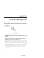
Appendix B Hands-Free Stand Operation
Appendix C Scanner Pinout Connections
Appendix D ASCII Chart
Appendix E European Union Directive Compliance
Glossary
Publication 2755-6.2
Preface
Using this Manual
Read this preface to familiarize yourself with the rest of the manual.
This preface covers the following topics:
•
•
•
•
intended audience
chapter contents
laser warning symbol
related publications
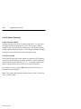
Intended Audience
No special knowledge is required to understand this document or use the
scanner. Decoded scanners may be connected to a variety of host
devices. We assume you are familiar with the host’s communication
ports.
Important: You will need the Bar Code Programming Guide for
Decoded Hand-Held Scanners (Publication 2755-6.5) to configure the
scanner and interface cables.
Publication 2755-6.2
P-2
Using this Manual
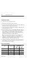
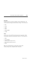
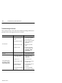
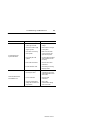
Contents of this Manual
The following table briefly describes the contents of each section.
Chapter
Title
Contents
Preface
Using this Manual
Describes the purpose, background, and scope
of this manual. Also provides a list of related
publications.
1
Scanner Features
Overview of the scanner. Includes read range
charts and description of accessory items.
2
Connecting and Operating
the Scanner
Describes how to connect the scanner to a host
device. Operating tips are also provided.
3
Configuring the Scanner
Describes how to configure the scanner using
the bar codes provided in the Bar Code
Programming Guide.
4
Communication Setup
(Cable Configuration)
Describes how to configure the scanner cables
using the bar codes provided in the Bar Code
Programming Guide.
Appendix A
Specifications
Provides physical, electrical and environmental
specifications.
Appendix B
Hands-Free Stand
Operation
Describes scanner automatic operation when
using the adjustable stands.
Appendix C
Scanner Connector
Pinouts
Provides scanner pinout signal names and a
brief description of each.
Appendix D
ASCII Chart
ASCII conversion chart also provides Code 39
Full ASCII encoded characters.
Appendix E
European Union Directive
Compliance
Provides requirements for scanners when used
within the European Union.
Glossary
Provides definitions of commonly used
teminology.
Bar Code Test Symbols
Sample symbols useful for testing the operation
of your bar code system.
Inside Back
Cover
Publication 2755-6.2
Using this Manual
P-3
Related Publications
Below is a list of related publications you may need to refer to when
using the scanner.
Publication No.
Title
2755-6.5
Bar Code Programming Guide
Provides the configuration bar codes for the decoded scanner and
interface cables.
2755-921
Bar Code Basics
Describes bar code symbologies, equipment, and typical applications.
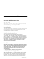
Laser Warning Symbol
Be aware of the following laser caution symbol.
Publication 2755-6.2
Chapter
1
Scanner Features
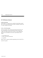
This chapter describes the features of the decoded scanner.
Included are descriptions of:
•
•
•
•
•
•
•
major features
LEDs
scanning ranges
configuration options
decoding
safety labels
accessories
Publication 2755-6.2
1-2
Scanner Features
Scanner Features
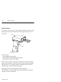
The scanners use a low power visible (red) laser diode for scanning. The
trigger turns on the laser which scans a label at approximately 36 scans
per second.
LEDs
Trigger
Cable Connector
The laser beam:
-exits through the scan window
-reflects off the label back through the window
-is detected by a sensor in the scanner
When a label is read, the laser beam is automatically turned off until the
trigger is pressed again. If no label is read, the laser beam automatically
turns off after 0.5 to 3 seconds (timeout is adjustable) and remains off
until the trigger is released and pressed again.
Note: When used with the adjustable stands (Catalog No.
2755-HFN-K1, -K2), the scanner operates automatically for hands-free
operation. Refer to Appendix B.
Publication 2755-6.2
Scanner Features
1-3
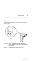
LED Indicators
On the back of the scanner there is a clear window through which two
LEDs are visible.
Green
Red
Green LED = Decode, indicating that a bar code symbol has been
scanned and decoded. LED remains on until the next scan
(trigger pressed).
Red LED = Scanning, indicating that the laser light is on.
Publication 2755-6.2
1-4
Scanner Features
Configuration Options
The scanner is readily adaptable to a wide variety of applications by
scanning configuration bar codes. The configuration bar codes control
the operation of:
• decoding
• laser light
• communications
Chapters 3 and 4 describe the configuration options.
Decoding
The scanner can decode the following symbologies:
•
•
•
•
•
•
•
UPC-A
EAN 8
Codabar
Code 39 Full ASCII
Interleaved 2 of 5
MSI Plessey
•
•
•
•
•
•
UPC-E
EAN 13
Code 39
Discrete 2 of 5
Code 128
Code 93
EAN 128
The scanner is autodiscriminating so that multiple symbologies may be
enabled at the same time. The only exception is the scanner cannot
discriminate between Code 39 and Code 39 Full ASCII.
Publication 2755-6.2
Scanner Features
1-5
Safety Labels
The scanners use a low power visible laser diode. As with any bright
light source, you should avoid staring directly into the beam.
Momentary exposure to a CDRH Class II laser is not known to be
harmful.
The following figure shows the location of all safety labels as they
appear on the scanner.
LASER LIGHT
DO NOT STARE INTO BEAM
CLASS 2 LASER PRODUCT
680nm LASER
1.0 MILLIWATT MAX OUTPUT
AVOID EXPOSURE
LASER LIGHT IS
EMITTED FROM
THIS APERATURE.
Appears on both sides.
RAYONNEMENT LASER
NE PAS REGARDER DANS LE FAISCEAU
APPAREIL A LASER DE CLASSE 2
LASER–STRAHLUNG
NICHT IN DEN STRAHL BLICKEN !
LASER KLASSE 2
COMPLIES WITH
IEC 825–1:1993/EN 60825
CAUTION – LASER LIGHT WHEN OPEN –
DO NOT STARE INTO BEAM.
ATTENTION – RAYONNEMENT LASER EN
CAS DOUVERTURE. NE PAS REGARDER
DANS LE FAISCEAU
VORSICHT!
LASERSTRAHL, WENN ABDECKUNG GEOEFFNET
Publication 2755-6.2
1-6
Scanner Features
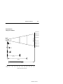
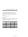
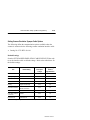
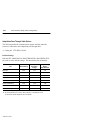
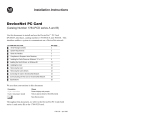
Scanning Ranges
The scanner can read bar code symbols at various distances depending
upon the bar code width (width of bars or spaces).
Minimum Bar Code
Width
Read Range
(Catalog No. 2755-HDG4)
Inches / Centimeters
4.0 mil
(.13 mm)
1.5 in to 2.0 in
(3.8 cm to 5.1 cm)
5.0 mil
(.13 mm)
1.25 in to 3.25 in
(3.2 cm to 8.2 cm)
7.5 mil
(.19 mm)
0.0 in to 7.0 in
(0.0 cm to 17.8 cm)
20.0 mil
(.51 mm)
0.0 in to 25.0 in
0.0 cm to 63.5 cm)
40.0 mil
(1.02 mm)
2.0 in to 40.0 in
(5.1 cm to 101.6 cm)
55.0 mil
(1.40 mm)
3.0 in to 55.0 in
(7.6 cm to 140 cm)
Publication 2755-6.2
Scanner Features
1-7
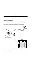
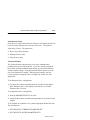
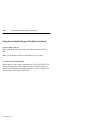
Decoded Scanner
Catalog No. 2755-HDG-4
20 (50.8 cm)
15 (38.1 cm)
10 (25.4 cm)
5 (12.7 cm)
Scan Width
Scanner
0
5 (12.7 cm)
4 mil
(0.10 mm)
10 (25.4 cm)
15 (38.1 cm)
20 (50.8 cm)
5 mil
(0.13 mm)
7.5 mil
(0.19 mm)
20 mil
(0.51 mm)
40 mil
(1.02 mm)
55 mil
(1.40 mm)
0
inches
centimeters
5
12.7
10
25
15
38
20
51
25
64
30
76
35
89
40
102
45
114
50
127
55
140
Distance From Front of Scanner
Publication 2755-6.2
1-8
Scanner Features
Accessories
The following accessories are available.
Scanner Cables – Connects scanner to Synapse
cable. See page 2–3 for connections.
• 8 ft. / 2.44 meter
(Catalog No. 2755-HDC-GS1-08)
• 20 ft. / 6.1 meter
(Catalog No. 2755-HDC-GS1-20)
RS-232 Synapse Cables – Provide RS-232
output. Cables are configurable.
See page 2-7 for connections.
• RS-232-C, 25-pin DB, male, Txd on Pin 3
(Catalog No. 2755-HFC-SR2-01)
• RS-232-C, 9-pin DB, female, Txd on Pin 2
(Catalog No. 2755-HFC-SR3-01)
Publication 2755-6.2
Scanner Features
1-9
Power Supplies – Connect to RS-232, keyboard
wedge or scanner emulation Synapse cable.
Provides power for the scanner ➀.
• 100 - 240 VAC, 50 - 60 Hz
(Catalog No. 2755-HFP-D1)
• Power cable for power supply, IEC 320,
terminated, US 110V AC
(Part No. 77121-801-01)
• Power cable for power supply, IEC 320,
unterminated, US 240V AC
(Part No. 77121-801-02)
• Power cable for power supply, IEC 320,
unterminated, European 240V AC
(Part No. 77121-801-03)
➀ Some applications may not require a power supply when the host provides adequate
power for the scanner. This ability of the host to power the scanner will vary with
system configurations. The scanner with cable requires 150 mA at 5 volts (typical).
Keyboard Wedge Synapse Cables – Connects
between keyboard and host device. Host device
receives decoded bar code data the same as
keyboard input. See page 2–8 for connections.
• For IBM XT/AT keyboard, 5-pin DIN
(Catalog No. 2755-HFC-SP1-01)
• For PS/2 keyboard, 6-pin Mini-DIN
(Catalog No. 2755-HFC-SP2-01)
• For DEC VT220, 320, 420 keyboards
(Catalog No. 2755-HFC-SV1-01)
• For DEC VT520 keyboards
(Catalog No. 2755-HFC-SV2-01)
Publication 2755-6.2
1-10
Scanner Features
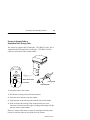
Scanner Emulation Synapse Cable – Provides
undecoded scanner output. See page 2-12 for
connections.
• (Catalog No. 2755-HFC-SA1-01)
AdaptaScan Pass Through Cable – Connects
scanner to custom cable for connection to
AdaptaScan RS-232 and power terminal blocks.
See page 2-10 for connections.
• RS-232-C, 25-pin DB, male, Txd on Pin 3
(Catalog No. 2755-HDC-GA2-08)
Adjustable Stands – Provide hands-free
operation. When placed into the stand, the
scanner automatically turns on and remains on
in a blinking mode. Any symbol passed under
the scan line is decoded. Has separate
adjustments for scanner angle and height.
• 5 to 18 inch (127 to 457 mm) height
(Catalog No. 2755-HFN-K1)
• 9 to 16 inch (229 to 406 mm) height
(Catalog No. 2755-HFN-K2)
Publication 2755-6.2
Scanner Features
1-11
Multi-mount Stand – Rubber coated, fixed
mount holder for counter or wall mounting.
The stand has the following approximate
dimensions: 3.5 x 4.0 x 6.5 inches (89 x 102 x
165 mm).
• (Catalog No. 2755-HFN-K3)
Protective Boot – Heavy canvas boot provides
additional protection for the scanner.
• (Catalog No. 2755-HFN-H1)
Publication 2755-6.2
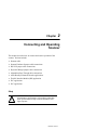
Chapter
2
Connecting and Operating
Scanner
This chapter describes how to connect and test the operation of the
scanner. Sections include:
•
•
•
•
•
•
•
•
•
Scanner cable
Scanner Emulator Synapse cable connections
RS-232 Synapse cable connections
Keyboard Wedge Synapse cable connections
AdaptaScan Pass Through cable connections
Allen-Bradley Enhanced Decoder applications
Flexible Interface Module (RB) application
PLC application
SLC application
Safety
!
ATTENTION: Caution - use of controls or
adjustments or performance of procedures other than
those specified herein may result in hazardous laser
light exposure.
Publication 2755-6.2
2-2
Connecting and Operating Scanner
Overview
The scanner may be connected to a variety of host devices through an
interface cable. The communication parameters for the cables are
configured by scanning bar codes. There are four types of cables:
•
•
•
•
Scanner Emulator Synapse cable
RS-232 Synapse cable
Keyboard Wedge Synapse cable
AdaptaScan Pass Through cable
Note: The AdaptaScan Pass Through cable (Catalog No.
2755-HDC-GA2-08) provides a physical link between the scanner’s
output connector and a user supplied custom cable connected to an
AdaptaScan Bar Code Reader’s RS-232 and power terminal blocks.
All configuration bar codes are in the Bar Code Programming Guide for
Decoded Hand-Held Scanners (Publication No. 2755-6.5).
Publication 2755-6.2
Connecting and Operating Scanner
2-3
Scanner to Synapse Cable or
AdaptaScan Pass Through Cable
The scanner to synapse cable (Catalog No. 2755-HDC-GS1-08, -20) or
AdaptaScan Pass Through cable (Catalog No. 2755-HDC-GA2-08)
connect to the bottom of the scanner handle.
Slot for Tab on Collar
Locking Collar
Connector
Cable Connector
To attach the cable to the scanner.
1. Pull back the locking collar from the connector.
2. Insert the cable connector into the scanner.
3. Align the tabs on the locking collar with the slots on the handle.
4. Push in and turn the locking collar counterclockwise to lock.
Connector is locked when flat edge of locking collar aligns with the
flat edge of the scanner handle.
Remove a scanner cable from a scanner by rotating the locking collar
clockwise until the cable can be pulled out of the scanner.
Publication 2755-6.2
2-4
Connecting and Operating Scanner
Scanner Cable to Synapse Cable Connection
To connect the scanner cable to a Synapse cable, push the cable into the
connector until you hear the connector snap in place. To remove the
scanner cable, press down on the small raised bump on the connector end
and remove cable.
Scanner Cable
Scanner
Press Here to Remove
Synapse Cable
(2755-HFC-SR3-01 shown)
Publication 2755-6.2
Connecting and Operating Scanner
2-5
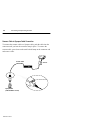
Scanner Emulation Synapse Cable Connections
Use the scanner emulation Synapse cable to provide undecoded output to
a scanner input port of a bar code decoder (cable has female 9-pin DB
connector). The following scanner emulation cable is available.
Catalog No. 2755-HFC-SA1-01
A separate power supply provides power to the scanner. The power
supply plugs into the scanner emulation Synapse cable.
Power Supply
Scanner Cable
Scanner
Scanner Emulation Synapse Cable
(2755-HFC-SA1-01)
Note: The power supply
should be connected last.
To Bar Code Decoder
!
ATTENTION: Do not install the scanner emulation
Synapse cable with power applied to either the Synapse
cable or decoder. Failure to follow this caution may result
in damage to the scanner, Synapse cable, or decoder.
Publication 2755-6.2
2-6
Connecting and Operating Scanner
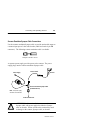
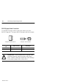
RS-232 Synapse Cable Connections
Use the RS-232 Synapse cable to connect the scanner to any host
RS-232C input port. Two types of RS-232 Synapse cables are available:
Catalog No. 2755-HFC-SR2-01
Catalog No. 2755-HFC-SR3-01
RS-232 Synapse
Cable
Output Connector
Output Signal
2755-HFC-SR2-01
Male 25-pin DB
RS-232C, Txd on Pin #3
2755-HFC-SR3-01
Female 9-pin DB
RS-232C, Txd on Pin #2
!
ATTENTION: Do not install the RS-232 Synapse cable
with power applied to either the Synapse cable or host
device. Failure to follow this caution may result in damage
to the scanner, Synapse cable, or host device.
Publication 2755-6.2
Connecting and Operating Scanner
2-7
Connect the scanner to an RS-232 port as shown below. A separate
power supply provides power to the scanner. The power supply plugs
into the RS-232 Synapse cable.
Scanner Cable
Power Supply
Scanner
RS-232 Synapse Cable
(2755-HFC-SR3-01 shown)
Note: The power supply
should be connected last.
To Host RS-232 Port
Host with RS-232 Port
Publication 2755-6.2
2-8
Connecting and Operating Scanner
Keyboard Wedge Synapse Cable Connections
Use the keyboard wedge Synapse cable to connect the scanner between a
keyboard and a host device. The host device interprets the decoded
scanner output the same as keyboard data. Four types of keyboard
wedge Synapse cables are available:
Catalog No. 2755-HFC-SP1-01
Catalog No. 2755-HFC-SP2-01
Catalog No. 2755-HFC-SV1-01
Catalog No. 2755-HFC-SV2-01
Keyboard Wedge
Synapse Cable
For Keyboard Type:
2755-HFC-SP1-01
IBM AT/XT Keyboard (5-pin DIN)
2755-HFC-SP2-01
PS/2 Keyboard (6-pin Mini-DIN)
2755-HFC-SV1-01
DEC VT220/320/420
2755-HFC-SV2-01
DEC VT520
A separate power supply plugs into the Synapse cable and provides
power to the scanner. The following wedge cable applications may not
require the power supply if the host provides adequate power for the
scanner (depends on system configuration):
•
•
•
•
IBM PC/AT
IBM PS / 2-50, 55SX, 60, 70, 80
IBM PC/XT and compatibles
IBM PS/2-30
Publication 2755-6.2
Connecting and Operating Scanner
Power Supply
(May not be required
see previous page.)
Scanner Cable
2-9
Scanner
Wedge Synapse Cable
(2755-HFC-SP1-01 shown)
Note: The power supply
should be connected last.
To Host
Keyboard Connector
To Keyboard
To connect the scanner cable to the keyboard wedge cable, push the
cable into the connector until you hear the connector snap in place. To
remove the scanner cable, press down on the small raised bump on the
connector end and remove cable.
!
ATTENTION: Do not install the wedge cable or
disconnect/connect the keyboard with power applied to
either the wedge cable or host device. Failure to follow
this caution may result in damage to the scanner, wedge
interface cable, or host device.
The wedge Synapse cable connects between the keyboard and the host
device. Unplug the keyboard and connect one end of the wedge cable to
the host keyboard input. Connect the other end of the wedge interface
cable to the keyboard.
Publication 2755-6.2
2-10
Connecting and Operating Scanner
AdaptaScan Pass Through Cable Connection
The standard Pass Through cable has a 25 pin male DB connector.
When connecting the cable to an AdaptaScan RS-232 terminal block,
you will need to attach an unterminated cable with a female 25 pin DB
connector on one end. Power for the scanner is provided by the package
detect terminal block connector.
Important: Power for the scanner (from Package Detect terminals) is
not provided until the Reader is installed on the wiring base.
AdaptaScan Pass Through Cable
Scanner
Custom Cable (see next page)
AdaptaScan Wiring Base
!
ATTENTION: Turn off all power to the AdaptaScan
wiring base before making cable connections. Failure to
follow this caution could result in electrical shock and/or
damage to the scanner or AdaptaScan wiring base.
Publication 2755-6.2
Connecting and Operating Scanner
2-11
The custom cable for the AdaptaScan Pass Through cable connects to the
RS-232 and package detect terminals in the AdaptaScan wiring base.
25-Pin
Female DB Connector
PKG DET
+12VDC
Custom Cable
Maximum length of
18 inches (.46 meter)
Ground
No Connection
Transmit (Tx)
No Connection
No Connection
Receive (Rx)
Clear to Send (CTS)
Ready to Send (RTS)
Shield (SHD)
AdaptaScan Wiring Base
The following table provides the pinout connections for the cable (DB
25-pin female connector).
Pass Through Cable
Pin Number
(DB25 Connector)
Function
AdaptaScan Terminal Connection
2
Receive Data Input
Tx (RS-232 Terminal Block)
3
Transmit Data Output
Rx (RS-232 Terminal Block)
4
CTS Input
RTS (RS–232 Terminal Block)
5
RTS Output
CTS (RS-232 Terminal Block)
7
Ground
GND (Package Detect Terminal Block)
9
+V 4.8 to 14.0V DC
12V (Package Detect Terminal Block)
Shield
Shield Ground
SHD (RS-232 Terminal Block)
Publication 2755-6.2
2-12
Connecting and Operating Scanner
Scanner to Enhanced Decoder Scanner Port Application
Use the Scanner Emulation Synapse cable (Catalog No.
2755-HFC-SA1-01) and Gun Adapter (Catalog No. 2755-NC16, Series
B) to connect the scanner cable to a scanner port on the Allen-Bradley
Enhanced Decoders (2755-DS1/DD1).
Power Supply
Scanner Cable
Scanner
Scanner Emulation Synapse Cable
(2755-HFC-SA1-01)
Note: The power supply
should be connected last.
Gun Adapter
(Catalog No. 2755-NC16 Series B)
Allen-Bradley
Enhanced Decoder
(2755-DS/DD)
!
ATTENTION: Use the Series B Gun Adapter (Catalog
No. 2755-NC16, Series B). The Series A Gun Adapter was
designed for earlier versions of the hand-held scanners
(such as 2755-G2, -G3) and will not work with the new
hand-held scanners.
Publication 2755-6.2
Connecting and Operating Scanner
2-13
Scanner to Enhanced Decoder Aux Port Application
Use the 25-pin RS–232 Synapse cable (Catalog No. 2755-HFC-SR2-01)
to connect the scanner cable to a Aux port on the Allen-Bradley
Enhanced Decoders (2755-DS1/DD1).
Scanner Cable
Power Supply
Scanner
25-pin RS-232 Synapse Cable
(2755-HFC-SR2-01)
Note: The power supply
should be connected last.
Null Modem
Allen-Bradley Enhanced Decoder
(2755-DS1/DD1)
Publication 2755-6.2
2-14
Connecting and Operating Scanner
Scanner to Flexible Interface (RB) Module Application
Use the 25-Pin RS-232 Synapse cable (Catalog No. 2755-HFC-SR2-01)
to connect the scanner cable to a port on the Flexible Interface Module
(Catalog No. 2760-RB). The protocol cartridges (Catalog No.
2760-SFC1, -SFC2) support RS-232 communications.
Scanner Cable
Power Supply
Scanner
RS-232 Synapse Cable
(2755-HFC-SR2-01)
Note: The power supply
should be connected last.
SFC1, SFC2 Protocol Cartridge
To RB Module Communications Port
Flexible Interface Module
Refer to the user manual for the Flexible Interface Module for the proper
configuration. Make sure the Synapse cable communications settings
match the Flexible Interface Module settings for the port.
Publication 2755-6.2
Connecting and Operating Scanner
2-15
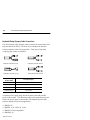
Scanner to PLC Application
Use the 25-Pin RS-232 Synapse cable (Catalog No. 2755-HFC-SR2-01)
to connect the scanner cable to the channel 0 port on a PLC-5. The
channel 0 port must be configured for RS-232 communications.
Power Supply
Scanner Cable
Scanner
RS-232 Synapse Cable
(2755-HFC-SR2-01)
Note: The power supply
should be connected last.
PLC-5
To Channel 0 Port
Refer to the user manuals for the Allen-Bradley 6200 Series
Programming Software to make sure the channel 0 settings match the
Synapse cable settings.
Publication 2755-6.2
2-16
Connecting and Operating Scanner
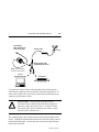
Scanner to SLC Application
Use the 9-Pin RS-232 Synapse cable (Catalog No. 2755-HFC-SR3-01) to
connect the scanner cable to the channel 0 port on an SLC-5/03 or 5/04.
The channel 0 port must be configured for RS-232 communications.
Scanner Cable
Power Supply
Scanner
RS-232 Synapse Cable
(2755-HFC-SR3-01)
Note: The power supply
should be connected last.
SLC 5/04
To Channel 0 Port
Channel 0
Refer to the user manuals for the Allen-Bradley Advanced Programming
Software (APS) to make sure the channel 0 settings match the Synapse
cable settings.
Publication 2755-6.2
Connecting and Operating Scanner
2-17
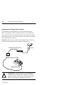
Operating the Scanner
1. Check your connections.
• Is the scanner cable securely attached?
• Is the scanner cable securely connected to the
Synapse cable?
• If a power supply is required, is there power
to the power supply and is the power supply
plugged into the Synapse cable?
2. Test the scanner
Aim the scanner at the work
surface and press the trigger.
You should see the red beam
on the work surface, and the
red LED on the back of the
scanner should be on.
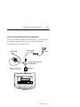
3. Scan a label.
Scan a bar code. Adjust the
scanner position so that the scan
beam is centered on the bar
code and overlaps both sides.
When the scanner has read a
symbol:
• You will hear a beep from the
scanner (if symbology has
been enabled, all symbologies enabled at default).
• The green LED will turn on
and remain on until the next
scan.
Publication 2755-6.2
2-18
Connecting and Operating Scanner
Automatic Shutoff
The scanner automatically stops scanning after a bar code symbol has
been read. The length of time the scanner remains on without reading a
label is configurable from 0.5 to 3 seconds. You must release and press
the trigger again to resume scanning.
Audible Response
When scanning a bar code symbol, listen for a single short beep from the
scanner. This beep indicates that the bar code has been successfully
scanned. Refer to the following tables for all other responses:
Beep During Normal Operation
This Response
Indicates
1 Beep (short high tone)
Bar code symbol decoded. Scanner audible
response must be enabled.
4 Beeps (long, low tone)
Format or transmission error detected. This error
occurs if the scanner is not properly configured. All
data is ignored. Verify option settings.
Beep During Configuration
This Response
Indicates
1 Beep (short high tone)
Bar code symbol decoded. Scanner audible
response must be enabled.
1 Beep (low / high tone)
Input error. Possible causes:
Incorrect bar code scanned
Cancel scanned
Incorrect configuration sequence
1 Beep (high / low tone)
Bar code scanned requiring a value. Scan in the
value using the configuration bar codes.
1 Beep (high / low / high / low tone)
Publication 2755-6.2
Configuration setting successfully changed.
Connecting and Operating Scanner
2-19
Beep During Code 39 Buffering
This Response
Indicates
1 Beep (high / low tone)
New Code 39 data entered into the buffer.
3 Beeps (long high tone)
Code 39 buffer is full.
1 Beep (low / high / low tone)
Buffer cleared or an attempt to transmit an empty
buffer occurred.
2 Beeps (long high tone)
Error in data transmission, check cable
connections.
1 Beep (low / high tone)
Transmission of buffer data successful.
Publication 2755-6.2
2-20
Connecting and Operating Scanner
Configuring the Scanner and Cables
Configure the scanner, Synapse and AdaptaScan Pass Through cables by
scanning the bar codes in the Bar Code Programming Guide for Decoded
Hand-Held Scanners (Publication 2755-6.5). The scanner is always
enabled to read the Code 128 configuration bar codes used for
configuring the scanner. Refer to:
• Scanner Configuration (Chapter 3)
• Communication Setup, Cable Configuration (Chapter 4)
Publication 2755-6.2
Chapter
3
Configuring the Scanner
This chapter describes the scanner configuration options.
Important Notes on Configuring a Scanner
Be aware of the following when configuring the scanner:
• Both the scanner and Synapse cable configuration bar codes are
located in the Bar Code Programming Guide for Hand-Held Scanners
(Publication 2755-6.5).
• Configure the scanner for use with a Synapse cable or AdaptaScan
Pass Through cable. Separate scanner configuration codes are used
for each cable type. Make sure you use the correct configuration
codes. The programming guide has separate tabbed sections for
Scanner Configuration (for Synapse Cable) and Scanner
Configuration (for AdaptaScan Pass Through Cable)
• Chapter 4 describes the communication setup (cable configuration)
codes for the RS-232, keyboard wedge cable, scanner emulation, and
AdaptaScan Pass Through cables.
Scanner Configuration Bar Codes
All programming codes may be found in the Bar Code Programming
Guide for Hand-Held Scanners (Publication 2755-6.5). The scanner is
always enabled to read Code 128 configuration labels since all
configuration codes use this symbology.
Publication 2755-6.2
3–2
Configuring the Scanner
Configuring the Scanner
1. Connect the interface cable to the scanner.
2. Apply power to the interface cable (if required).
3. Scan the SCAN THIS SYMBOL FIRST bar code (found in Bar Code
Programming Guide, see page references below).
4. Then scan the SET SCANNER FOR (SYNAPSE or ADAPTASCAN)
CABLE OPERATION bar code.
5. Select the scanner cable type. Scan ENABLE SYNAPSE CABLE if
you are using one of the Synapse cables (RS-232, keyboard wedge, or
scanner emulation). Scan the ENABLE ADAPTASCAN PASS
THROUGH CABLE bar code if you are using the AdaptaScan Pass
Through cable (Catalog No. 2755-HDC-GA2-08).
Note: The scanner stores the Synapse cable and AdaptaScan pass
through cable configurations separately. To change between
configurations, scan the ENABLE SYNAPSE CABLE or ENABLE
ADAPTASCAN PASS THROUGH CABLE bar code.
6. Configure the scanner by scanning the bar codes for the options you
want to change. The scanner is currently set with default settings as
listed on this and the following page.
Scanner Default Settings
Item
Default Setting
Programming Guide ➀
Page Reference
For AdaptaScan
For All Other
Cable
Cables
Cable Type
AdaptaScan Pass
Through Cable
2-2
1-2
Symbologies
All Enabled
2-4
1-4
Transmit UPC-A Check Digit
Enabled
2-8
1-8
Transmit UPC-E Check Digit
Enabled
2-8
1-8
Convert UPC-E to UPC-A
Disabled
2-8
1-8
EAN Zero Extend
Disabled
2-9
1-9
Publication 2755-6.2
Configuring the Scanner
Item
Decode UPC / EAN
Supplemental
Default Setting
3–3
Programming Guide ➀
Page Reference
For AdaptaScan
For All Other
Cable
Cables
Disabled
2-9
1-9
UPC-A Preamble
System Character
2-10
1-10
UPC-E Preamble
System Character
2-10
1-10
0
2-11
1-11
CLSI Editing
Disabled
2-12
1-12
NOTIS Editing
Disabled
2-12
1-12
Codabar Decode Redundancy
Disabled
2-12
1-12
Transmit Code 39 Check Digit
Disabled
2-13
1-13
Buffer Code 39
Disabled
2-13
1-13
Code 39 Full ASCII
Disabled
2-13
1-13
One
2-14
1-14
Mod 10 - Mod 10
2-14
1-14
Convert Interleaved 2 of 5 (14
digit) to EAN 13
Disabled
2-15
1-15
Interleaved 2 of 5 Code Length
14
2-15
1-15
Discrete 2 of 5 Code Length
12
2-15
1-15
Prefix
None
2-17
1-17
Suffix
None
2-17
1-17
Data Transmission Format
➁
2-19
1-19
Transmit No-Read Message
Disabled
2-19
1-20
Transmit Code ID Character
Disabled
2-20
1-20
Transmit AIm ID Character
Disabled
2-20
1-21
Audible Response
Enabled
2-21
1-21
UPC/EAN Security Level
MSI Plessey Check Digit
MSI Plessey 2 Check Digit
Algorithm
➂
2-21
1-21
Laser On Timeout
3 Seconds
2-22
1-22
Hands-FreeOperationTimeout
60 minutes
2-24
1-23
Power Mode
➀ Bar Code Programming Guide for Decoded Scanners (Publication No. 2755-6.5)
➁ for AdaptaScan Cable = Suffix Only, for Synapse Cable = Data As Is
➂ for AdaptaScan Cable = Low Power, for Synapse Cable = Continuous
Publication 2755-6.2
3–4
Configuring the Scanner
Select Cable Type
Important: Select the cable type before configuring the scanner. The
scanner configuration codes (and some options) for each cable type
(Synapse and AdaptaScan Pass Through) are different. Each
configuration is stored separately. The selections are:
• Enable Synapse Cable
• Enable AdaptaScan Pass Through Cable (default)
After configuring the scanner, you can switch between configurations by
scanning the cable selection bar code.
Select Symbologies
Scan the bar code labels for the symbologies you want the scanner to
decode. Only enable the symbologies you expect to read. The scanner
automatically discriminates between all of the following symbologies.
The only exception is that the scanner cannot discriminate between Code
39 and Code 39 Full ASCII. The scanner can read and decode the
following symbologies. All symbologies are enabled by default.
UPC-A
UPC-E
Code 39
Code 39 Full ASCII
EAN 8
EAN 13
Interleaved 2 of 5
Discrete 2 of 5
Codabar
Code 128
MSI / Plessey
Code 93
EAN 128
To enable a symbology, scan the ENABLE bar code for the symbology.
To disable a symbology, scan the DISABLE bar code.
Publication 2755-6.2
Configuring the Scanner
3–5
UPC / EAN Options
The following options are available for UPC-A and UPC-E codes:
Transmit UPC-A Check Digit
When enabled, UPC-A symbol data is transmitted with the check digit.
Enabled is the default.
Transmit UPC-E Check Digit
When enabled, UPC-E symbol data is transmitted with the check digit.
Enabled is the default.
Convert UPC-E to UPC-A
When enabled, this option converts UPC-E (zero suppressed) decoded
data to a UPC-A format before sending the data. After conversion,
output data will be affected by UPC-A programming selections such as
preamble and check digit settings. Disabled is the default.
Decode UPC / EAN Supplemental
When enabled, supplemental digits are decoded. If the supplemental
digits are not enabled and a symbol having supplemental digits is read,
the supplemental digits are ignored. On the other hand, if supplemental
digits are enabled, only symbols with supplemental digits are decoded.
Disabled is the default.
Autodiscriminate UPC / EAN with Supplementals
When enabled, supplemental digits are decoded. Both codes with and
without supplemental digits are decoded. Disabled is the default.
Publication 2755-6.2
3–6
Configuring the Scanner
UPC / EAN Options (Continued)
EAN 8 Zero Extend
When enabled, five leading zeros are added to decoded EAN 8 symbol
data. The five zeros make the EAN 8 symbols compatible with the EAN
13 format. Disabled is the default.
UPC-A / UPC-E Preambles
The UPC preamble consists of the system character and country code.
The system character is the the first character on the left side of the
symbol. The country code for UPC is always 0. Select whether these
characters are sent with the bar code data. System character is the
default.
• system character only
• country code and system character
• no preamble
Note: There are separate preamble programming codes for both UPC-A
and UPC-E symbols.
Publication 2755-6.2
Configuring the Scanner
3–7
UPC / EAN Decode Security Levels
There are four levels of decode security. There is an inverse relationship
between security and the ability to decode codes of varying quality.
Increasing the security level, “tightens” the scanner’s requirements for a
valid read. Select one of the levels below.
The default security level is 0. This level is sufficient for most
applications. Higher security levels:
• may result in more no-reads on poor quality labels
• reduce the chance of mis-reads on poor quality labels
Security Level
Decode Operation
0
At the level 0, the scanner decodes many poor or low quality codes while
providing adequate security for UPC/EAN codes within specifications.
1
As the quality level of UPC / EAN bar codes decrease, certain digits are
more susceptible to misreads ( 1, 2, 7, 8) If you have problems only
decoding symbols with these digits, select this security level.
2
If you are having problems decoding poor quality bar codes and the
problem isn’t limited to the digits ( 1, 2, 7, 8), select this level.
3
If you selected security level 2 and are still having problems decoding
symbols, select this security level.
Note: Only select this level if you are scanning high quality bar codes. The
scanner will reject codes that are not within the specifications for the
symbology.
Publication 2755-6.2
3–8
Configuring the Scanner
Codabar Options
The following options are available for Codabar bar codes:
NOTIS Editing
When enabled, the scanner removes the start and stop characters from the
decoded symbol data.
CLSI Editing
When enabled, the scanner removes the start and stop characters and
inserts a space after the 1st, 5th, and 10th characters of a 14 character
Codabar Symbol.
Note: Symbol length does not include start and stop characters.
Decode Redundancy for Codabar
When enabled, a Codabar symbol must be read in both directions before
being decoded.
Publication 2755-6.2
Configuring the Scanner
3–9
Code 39 Options
The following options are available for Code 39 symbols.
Code 39 Check Digit
When enabled, the scanner verifies the Code 39 check digit (modulo 43
check character).
Code 39 Buffering (Scan and Store)
When enabled, the scanner stores all Code 39 symbol data that has a
leading space as the first character (following start pattern). As Code 39
labels are scanned for buffering, the scanner provides a high/low beep to
indicate that the data is stored in the buffer.
Up to 250 bytes of information may be stored. If you scan a symbol and
the buffer is full, the scanner will provide three long high tone beeps. No
transmission will occur and the data in the buffer is not affected.
Note: Before you can disable Code 39 buffering, you must clear the
buffer (see below).
Clear Transmission Buffer
Clears the Code 39 transmission buffer. You will hear a high/low/high
beep after the buffer has been cleared. No data is transmitted.
Publication 2755-6.2
3–10
Configuring the Scanner
Code 39 Options (Continued)
Send Transmission Buffer
Sends the contents of the Code 39 transmission buffer. You will hear a
low/high beep after the buffer has been sent. You can also send the
contents of the Code 39 buffer by scanning any Code 39 label with any
leading character other than a space. If you attempt to transmit an empty
buffer, the scanner will provide a short low/high/low beep.
Code 39 Full ASCII
The full ASCII option allows the scanner to output any ASCII character
or control code (including non-printable characters). When enabled, the
scanner interprets some characters ($, +, %, /) as special control codes.
Refer to Appendix E for a list of the Code 39 Full ASCII codes.
For example, scanning a symbol $H results in the ASCII code for a
Backspace being transmitted.
Note: The scanner cannot autodiscriminate between Code 39 and Code
39 Full ASCII symbols.
Publication 2755-6.2
Configuring the Scanner
3–11
MSI Plessey Options
The following options are available for MSI Plessey codes:
MSI Plessey Check Digit
When enabled, the scanner verifies the one or two digit check character
before transmitting the data. Check digits are not included in the
transmitted data.
MSI Plessey 2 Check Digit Algorithm
When enabled, the scanner performs an additional verification. You
must select either Mod 10 - Mod 10 (Default) or Mod 11 - Mod 11 check
digits.
Publication 2755-6.2
3–12
Configuring the Scanner
I 2-of-5 and Discrete 2-of-5 Options
The following options are available for Interleaved and Discrete 2 of 5
symbols:
I 2 of 5 (14 digit) to EAN 13 Conversion
When enabled, 14 character Interleaved 2 of 5 data is converted and
transmitted in an EAN 13 format.
Note: Interleaved 2 of 5 must be enabled and one code length (Length 1
or Length 2) must be set to 14. In addition, the code must have a leading
0 and a valid EAN 13 check digit.
Code Lengths
Specifies the expected length of the bar code symbol. When a specific
length is enabled, symbols that are not the specified length are ignored.
Only one or two lengths may be specified, all other lengths are ignored.
First scan the length symbol followed by the 2 digit length. Length 1
may range from 01 to 31. Length 2 may be in the range of 00 to 31.
Determine the number of characters in a symbol by counting the number
of printed digits (human readable characters).
Note: The scanner cannot be configured to read Interleaved or Discrete
2-of-5 labels of “any length”. You must specify code length(s).
Publication 2755-6.2
Configuring the Scanner
3–13
Data Format Options
The following options define the what happens to the data after a symbol
has been decoded:
Data Prefix / Suffix
To add prefix or suffix data to bar code data, scan the prefix or suffix bar
code followed by the 4 digit ASCII equivalent value for each character
(refer to Appendix D for the ASCII chart). Only one character may be
specified as a suffix or prefix. When you enter the last digit of a prefix
or suffix, the scanner lets you know that you have entered a valid value
by providing a high-low-high beep.
Data Transmission Formats
You can set whether or not prefix or suffix data is added to the decoded
symbol data. You have four options:
•
•
•
•
<DATA> only bar code data is sent
<PREFIX> <DATA> prefix data is sent then the bar code data
<DATA> <SUFFIX> bar code data is sent then the suffix data
<PREFIX><DATA><SUFFIX> prefix data is sent then bar code
data followed by the suffix data
Transmit NO READ Message
When enabled, a NR is transmitted with each no-read. If enabled, a
prefix and suffix will appear with the NR output message.
Publication 2755-6.2
3–14
Configuring the Scanner
Transmit Code ID Character
The code ID identifies a scanned bar code symbol’s code type.
If enabled, the code ID is sent after the prefix and before the bar code
data. The code ID codes are:
A = UPC-A, UPC-E, or EAN 13
B = Code 39
C = Codabar
D = Code 128
E = Code 93
F = Interleaved 2 of 5
G = Discrete 2 of 5
J = MSI Plessey
K = EAN 128
Transmit AIM ID Character
When enabled, the AIM code identifier is sent after the prefix and before
the bar code data. The identifier is a three character prefix. Refer to the
following:
Each AIM Code Identifier contains the 3-character string ]cm where:
]
=
Flag Character (ASCII 93)
c
=
Code Character (see table below)
m
=
Modifier (see table on next pages)
Code Character /
Generic Identifier
Code Type
A / ]A0
Code 39
C / ]C0
Code 128
E / ]E0
UPC/EAN
I / ]I0
Interleaved 2 of 5
Publication 2755-6.2
Configuring the Scanner
3–15
The modifier character is the sum of the applicable option values based
on the following table.
Code Type
Code 39
Option Value
Option
0
1
2
No Check character or Full ASCII processing.
Reader has checked one check character.
Reader has stripped check character.
Reader has performed Full ASCII character
conversion.
A Full ASCII bar code 1234 with check character W,
A+I+MI+DW, can be transmitted as ]A71234 where
7 = (1+2+4).
Standard data packet. No Function code 1 in first
symbol position.
Function code 1 in first symbol character position.
Function code 1 in second symbol character position.
A Code (EAN) 128 bar code 12345 with Function 1
character in the first position, Fcnt112345 will
transmitted as ]C112345.
Standard packet in full EAN country code format,
which is 13 digits for UPC-A and UPC-E (not including
supplemental data).
Two digit supplement data only.
Five digit supplement data only.
EAN-8 data packet.
A UPC-A bar code 012345678905 will be transmitted
as ]E00012345678905.
No check digit processing.
Reader has checked check digit.
Reader has stripped check digit before transmission.
4
Example:
0
Code 128
1
2
Example:
0
EAN/UPC
1
2
4
Example:
Interleaved
2 of 5
0
1
2
Example:
An I 2 of 5 bar code without check digit, 4123 will be
transmitted as ]I04123.
Publication 2755-6.2
3–16
Configuring the Scanner
According to AIM standards, a UPC with supplemental bar code is
transmitted in one of the following formats:
]E0 (UPC chars) (terminator) ]E2 (supplemental) (terminator) or
]E2 (supplemental) (terminator) ]E0 (UPC chars) (terminator)
In the 2755-HDG-4, however, this format is changed to:
]E0 (UPC chars) ]E2 (supplemental)
Therefore, a UPC with two supplemental characters, 01234567890510,
will be transmitted as a 21-character string ]E00012345678905]E110.
Publication 2755-6.2
Configuring the Scanner
3–17
Laser Control and Audible Response Options
Beep After Decode
When enabled, the scanner will beep after a symbol has been decoded.
We recommend that you leave this option enabled.
Laser On Time Out
This setting determines the maximum time the scanner remains on while
the trigger is pressed. The time out is programmable in 0.5 second
increments from 0.5 seconds to 5.0 seconds.
Hands-Free Stand Operation Timeout
If the scanner is used with an adjustable stand (Catalog No.
2755-HFN-K1, -K2), the scanner operates without pressing the trigger.
Refer to Appendix C for hands-free operation. The timeout determines
how long the scanner scans for a label before reducing the scan rate and
beam intensity. The scanner will resume scanning at the normal rate
when a label is presented. The timeout is selectable in 15 minute
intervals between 15 and 90 minutes.
Power Mode
Determines whether or not the scanner power remains on after a decode
attempt. With low power mode enabled, the scanner powers down after
each attempted decode. With continuous power mode enabled, the
scanner remains on at all times. We recommend that you use the
following settings:
• low power mode for AdaptaScan Pass Through cable
• continuous power mode for Synapse cables
Note: When the scanner is in low power mode and a label is scanned,
the first character of the first symbol will not be read as the scanner
powers up. Use continuous mode if this causes a problem with your
application (such as stand mode or A-B Basic Module applications).
Publication 2755-6.2
Chapter
4
Communication Setup (Cable
Configuration)
This chapter describes the configuration of scanner communication
parameters. The types of options available depends on the interface
cable you are using.
For This Cable
See These Pages:
RS-232 Synapse Cables
4-2 through 4-8
IBM PC Keyboard Wedge Synapse Cables
4-9 through 4-12
DEC VT520 Keyboard Wedge Synapse Cable
4-13 through 4-15
DEC VT220, VT320, VT420 Keyboard Wedge Synapse Cable
4-16 through 4-18
Scanner Emulation Synapse Cable
4-19 through 4-23
AdaptaScan Pass Through Cable
4-24 through 4-29
Important: All programming codes are in the Bar Code Programming
Guide for Hand-Held Scanners (Publication 2755-6.5).
Cable Defaults
To set cable defaults, scan the default label for the interface cable you are
using. Refer to each cable section for a table listing the defaults. The
selections for cable defaults are:
•
•
•
•
•
Set RS-232 Synapse Cable Defaults
Set IBM PC Keyboard Wedge Synapse Cable Defaults
Set DEC VT 520 Keyboard Wedge Synapse Cable Defaults
Set DEC VT VT220, VT320, VT420 Wedge Synapse Cable Defaults
Set AdaptaScan Pass Through Synapse Cable Defaults
Publication 2755-6.2
4-2
Communication Setup (Cable Configuration)
Setting RS-232 Synapse Cable Options
The following define the communication options available when the
scanner is connected to one of the following RS-232 Synapse cables:
• Catalog No. 2755-HFC-SR2-01
• Catalog No. 2755-HFC-SR3-01
Default Settings
Scanning the SET RS-232 SYNAPSE CABLE DEFAULTS bar code sets
the following parameters:
Item
Default Setting
Refer to
Description
on Page:
Programming
Guide ➀
Page Reference
Host
Standard RS-232
4-3
3-3
Baud Rate
9600
4-3
3-4
Parity
None
4-4
3-5
Check Parity
Enabled
4-4
3-5
Stop Bits
1
4-4
3-6
Data Bits
8
4-4
3-6
Hardware
Handshaking
None
4-5
3-7
RTS State
Low
4-5
3-7
Software
Handshaking
None
4-6
3-8
Beep on BEL
Enabled
4-7
3-9
Unknown Characters Send Bar Codes With
Unknown Characters
4-7
3-9
Response Timeout
2 seconds
4-7
3-10
Parameter Set
Set #1
4-8
3-12
➀ Bar Code Programming Guide for Decoded Scanners (Publication 2755-6.5).
Publication 2755-6.2
Communication Setup (Cable Configuration)
4-3
Host Selection
Currently, the only host selection is for standard RS-232
communications. Additional host selections may be added in the future.
• Standard RS-232 (default)
Baud Rate
Sets the rate (bits per second) at which the scanner transmits data.
The scanner baud rate setting must match the host setting.
The selections are:
•
•
•
•
•
•
•
•
110
300
600
1200
2400
4800
9600 (default)
19200
Publication 2755-6.2
4-4
Communication Setup (Cable Configuration)
Setting RS-232 Synapse Cable Options (Continued)
Parity
Set the parity of each ASCII coded character that is transmitted. Make
sure the parity matches the requirements of the host. The selections are:
•
•
•
•
•
Odd
Even
Mark (parity bit always set to 1)
Space (parity bit always set to 0)
None (default)
Check Parity
When enabled, the scanner checks the parity bit.
Number of Stop Bits
The stop bit marks the end of each character transmitted. Set the number
of stop bits to match the host device. The selections are:
• 1 Stop Bit (default)
• 2 Stop Bits
Data Bits
Determines the number of data bits for each ASCII character. The
selections are:
• 7 data bits
• 8 data bits (default)
Publication 2755-6.2
Communication Setup (Cable Configuration)
4-5
Hardware Handshaking
When enabled, handshaking verifies the readiness of a receiving device
before data is transmitted. You can enable or disable the hardware
handshaking lines. The DTR (Data Terminal Ready) signal is either
active high or low (see below).
This is how the scanner handshaking functions:
1. The scanner checks the Clear to Send (CTS) line. If CTS is active,
the scanner will wait for up to 2 seconds and check the line again. If
the line is still active, the scanner will provide an audible beep and
any scanned data will be lost.
2. If the CTS line is not active, the scanner will assert the Request to
Send (RTS) line and wait for two seconds for the host to assert the
CTS line. When the host asserts the CTS line, the scanner transmits
the data.
3. After the transmission is completed, the scanner will negate the RTS.
4. The host device should then negate CTS. The scanner checks the
CTS line on the next transmission.
RTS State
Selects the active state for the Request to Send (RTS) signal.
Make sure that this setting matches the requirements of the host device.
The selections are:
• RTS State Low (default)
• RTS State High
Publication 2755-6.2
4-6
Communication Setup (Cable Configuration)
Setting RS-232 Synapse Cable Options (Continued)
Software Handshaking
Software handshaking controls the transmission of data. Use software
handshaking instead of (but not with) hardware handshaking. There are
four options:
•
•
•
•
•
None (default)
ACK/NAK Only
ENQ Only
ACK/NAK with ENQ
XON/XOFF
ACK/NAK Only checks the result of a transmission. The scanner waits
for one of two responses from the host: ACK which means a successful
transmission or NAK which means there was a problem. Whenever the
scanner receives a NAK, it retransmits the data up to three times. If an
ACK is still not received after three attempts, the transmission is aborted
and the scanner will provide four short beeps.
ENQ ONLY requires that the scanner receive an enquire character
(ENQ) from the host before sending data. With ENQ enabled, the
scanner must receive an ENQ from the host within a two second period
after the last scan or a transmission error occurs. The scanner will
provide four short beeps to indicate the error.
ACK/NAK with ENQ combines both ACK/NAK and ENQ options.
With XON/ XOFF enabled, the interface cable assumes an XON for the
first transmission. The scanner will transmit data until an XOFF is
received from the host device. If an XON is not received within 30
seconds after an XOFF, a transmission error occurs.
Publication 2755-6.2
Communication Setup (Cable Configuration)
4-7
Beep on BEL
When enabled, the scanner will beep when a <BEL> character is
detected on the RS-232 link. <BEL> may be used to indicate an event
such as an illegal entry.
Unknown Characters
Unknown characters are characters not recognized by the scanner. When
SEND BAR CODES WITH UNKNOWN CHARACTERS is enabled,
all decoded bar code data is transmitted except for the unknown
characters. If this option is disabled, bar codes containing one or more
unknown characters are not transmitted.
Response Timeout
The response timeout determines the maximum amount of time the
scanner will wait before it assumes the end of a transmission. The
timeout period may be from 0.0 to 9.9 seconds in 0.1 second increments.
The default is 2.0 seconds.
To enter a new timeout, scan the timeout label followed by the two digit
timeout. The decimal point is fixed between the first and second digits.
Publication 2755-6.2
4-8
Communication Setup (Cable Configuration)
Setting RS-232 Synapse Cable Options (Continued)
Advanced Features
The advanced feature options allow you to store communication
parameters for up to two applications. If you have already configured
the scanner, all of the communication settings are stored as Parameter 1
settings (default setting). Using the advanced feature options, you can
also create Parameter 2 settings. When using the scanner, scan the
correct parameter setting bar code to configure the scanner for each
application.
To set Parameter Set 1 configuration:
1. Configure the scanner communications as described in this chapter.
Since Parameter Set 1 is the default you do not have to scan the
Parameter Set 1 bar code.
To set Parameter Set 2 configuration:
1. Scan the PARAMETER SET 2 bar code.
2. Configure the scanner communication parameters as described in this
chapter.
To set defaults for a parameter set, scan the appropriate default bar code.
The selections are:
• SET CABLE DEFAULTS CURRENT PARAMETER SET
• SET CABLE DEFAULTS BOTH PARAMETER SETS
Publication 2755-6.2
Communication Setup (Cable Configuration)
4-9
Setting IBM PC Keyboard Wedge Synapse Cable Options
The following define the communication options available when the
scanner is connected to one of the following IBM AT/XT or PS/2
keyboard wedge Synapse cables:
• Catalog No. 2755-HFC-SP1-01
• Catalog No. 2755-HFC-SP2-01
Defaults Settings
Scan the SET PC WEDGE SYNAPSE CABLE DEFAULTS bar code to
set the interface cable to default settings. The following table lists the
default settings.
Default Setting
Refer to
Description
on Page:
Programming
Guide ➀
Page Reference
IBM PC/AT
IBM PS/2-50, 55SX, 60, 70,
80
4-10
4-2
Country
North American
4-10
4-3
Bar Codes with
Unknown Characters
Send Bar Codes With
Unknown Characters
4-11
4-4
Intercharacter Delay
5 milliseconds
4-11
4-4
Parameter Set
Parameter Set 1
4-12
4-5
Item
Host
➀ Bar Code Programming Guide for Decoded Scanners (Publication 2755-6.5).
Publication 2755-6.2
4-10
Communication Setup (Cable Configuration)
Setting IBM PC Keyboard Wedge Interface
Synapse Cable Options (Continued)
Host Selection
Select the type of host the scanner will be communicating with.
The selections are:
•
•
•
•
IBM PC/AT , PS/2-50, 55SX, 60, 70, 80 (default)
IBM PC/XT
IBM PS/2-30
NCR 7052
Country Selection
Select the country for the keyboard type the interface cable is connected
to. The selections are:
•
•
•
•
•
•
•
•
North American (default)
German
French
French International
Spanish
Italian
Swedish
British
Publication 2755-6.2
Communication Setup (Cable Configuration)
4-11
Unknown Characters
Unknown characters are characters not recognized by the scanner. When
SEND BAR CODES WITH UNKNOWN CHARACTERS is enabled
(default), all decoded bar code data is transmitted except for the
unknown characters. If this option is disabled, bar codes containing one
or more unknown characters are not transmitted.
Intercharacter Delay
Setting an intercharacter delay provides the host time to perform
processing tasks between characters. The default is short delay (5 msec).
The options are:
• Short 5 msec delay (default)
• Medium 50 msec delay
• Long 99 msec delay
Publication 2755-6.2
4-12
Communication Setup (Cable Configuration)
Setting IBM PC Keyboard Wedge Interface
Synapse Cable Options (Continued)
Advanced Features
The advanced feature options allow you to store communication
parameters for up to two applications. If you have already configured
the scanner, all of the communication settings are stored as Parameter 1
settings (default setting). Using the advanced feature options, you can
also create Parameter 2 settings. When using the scanner, scan the
correct parameter setting bar code to configure the scanner for each
application.
To use and/or set Parameter Set 1 configuration:
1. Configure the scanner communications as described in this chapter.
Since Parameter Set 1 is the default you do not have to scan the
Parameter Set 1 bar code.
To use and/or set Parameter Set 2 configuration:
1. Scan the PARAMETER SET 2 bar code.
2. Configure the scanner communication parameters as described in this
chapter.
To set defaults for a parameter set, scan the appropriate default bar code.
The selections are:
• SET CABLE DEFAULTS CURRENT PARAMETER SET
• SET CABLE DEFAULTS BOTH PARAMETER SETS
Publication 2755-6.2
Communication Setup (Cable Configuration)
4-13
Setting DEC VT520 Keyboard Wedge Synapse Cable Options
The following define the communication options available when the
scanner is connected to one of the following DEC keyboard wedge
Synapse cable:
• Catalog No. 2755-HFC-SV2-01
Default Settings
Scan the SET DEC VT 520 KEYBOARD WEDGE SYNAPSE CABLE
DEFAULTS bar code to set the interface cable to default settings. Refer
to the table below for the default settings.
Item
Default Setting
Refer to
Description
on Page:
Programming
Guide➀
Page Reference
Host
DEC VT520
4-14
5-2
Country
North American
4-14
5-2
Unknown Characters
Send Bar Codes With
Unknown Characters
4-14
5-4
Intercharacter Delay
5 Millisecond
4-15
5-4
Parameter Set
Parameter Set 1
4-15
5-5
➀ Bar Code Programming Guide for Decoded Scanners (Publication 2755-6.5).
Publication 2755-6.2
4-14
Communication Setup (Cable Configuration)
Setting DEC VT520 Keyboard Wedge Interface
Synapse Cable Options (Continued)
Host Selection
Select the type of host the scanner will be communicating with.
The selections are:
• DEC VT520 (default)
• DEC VT520 with PS/2 Keyboard
Country Selection
Select the country for the keyboard type the interface cable is connected
to. The selections are:
•
•
•
•
•
•
•
•
North American (default)
German
French
French International
Spanish
Italian
Swedish
British
Unknown Characters
Unknown characters are characters not recognized by the scanner. When
SEND BAR CODES WITH UNKNOWN CHARACTERS is enabled
(default), all decoded bar code data is transmitted except for the
unknown characters. If this option is disabled, bar codes containing one
or more unknown characters are not transmitted.
Publication 2755-6.2
Communication Setup (Cable Configuration)
4-15
Intercharacter Delay
Some devices require a delay between characters to simulate the effect of
keystroke delays (characters are sent at a lower rate). The default is
short delay (5 msec). The options are:
• Short 5 msec delay (default)
• Medium 50 msec delay
• Long 99 msec delay
Advanced Features
The advanced feature options allow you to store communication
parameters for up to two applications. If you have already configured
the scanner, all of the communication settings are stored as Parameter 1
settings (default setting). Using the advanced feature options, you can
also create Parameter 2 settings. When using the scanner, scan the
correct parameter setting bar code to configure the scanner for each
application.
To set Parameter Set 1 configuration:
1. Configure the scanner communications as described in this chapter.
Since Parameter Set 1 is the default you do not have to scan the
Parameter Set 1 bar code.
To set Parameter Set 2 configuration:
1. Scan the PARAMETER SET 2 bar code.
2. Configure the scanner communication parameters as described in this
chapter.
To set defaults for a parameter set, scan the appropriate default bar code.
The selections are:
• SET DEFAULTS CURRENT PARAMETER SET
• SET DEFAULTS BOTH PARAMETER SETS
Publication 2755-6.2
4-16
Communication Setup (Cable Configuration)
Setting DEC VT220 / VT320 / VT420 Keyboard Wedge
Synapse Cable Options
The following define the communication options available when the
scanner is connected to the following DEC keyboard wedge interface
cable:
• Catalog No. 2755-HFC-SV1-01
Default Settings
Scan the SET DEC VT 220/320/420 WEDGE SYNAPSE CABLE
DEFAULTS bar code to set the interface cable to default settings. The
table below lists the defaults.
Item
Default Setting
Refer to
Description
on Page:
Programming
Guide ➀
Page Reference
Host
DEC VT220 / 320
4-16
6-2
Country
North American
4-17
6-2
Unknown Characters
Send Bar Codes With
Unknown Characters
4-17
6-4
Intercharacter Delay
5 Millisecond
4-17
6-4
Parameter Set
Parameter Set 1
4-18
6-5
➀ Bar Code Programming Guide for Decoded Scanners (Publication 2755-6.5).
Host Selection
Select the type of host the scanner will be communicating with.
The selections are:
• DEC VT 220/320 (default)
• DEC VT420
Publication 2755-6.2
Communication Setup (Cable Configuration)
4-17
Country Selection
Select the country for the keyboard type the interface cable is connected
to. The selections are:
•
•
•
•
•
•
•
•
North American (default)
German
French
French International
Spanish
Italian
Swedish
British
Unknown Characters
Unknown characters are characters not recognized by the scanner. When
SEND BAR CODES WITH UNKNOWN CHARACTERS is enabled
(default), all decoded bar code data is transmitted except for the
unknown characters. If this option is disabled, bar codes containing one
or more unknown characters are not transmitted.
Intercharacter Delay
Some devices require a delay between characters to simulate the effect of
keystroke delays (characters are sent at a lower rate). The default is
short delay (5 msec). The options are:
• Short 5 msec delay (default)
• Medium 50 msec delay
• Long 99 msec delay
Publication 2755-6.2
4-18
Communication Setup (Cable Configuration)
Setting DEC VT220 / VT320 / VT420 Keyboard Wedge
Synapse Cable Options (Continued)
Advanced Features
The advanced feature options allow you to store communication
parameters for up to two applications. If you have already configured
the scanner, all of the communication settings are stored as Parameter 1
settings (default setting). Using the advanced feature options, you can
also create Parameter 2 settings. When using the scanner, scan the
correct parameter setting bar code to configure the scanner for each
application.
To set Parameter Set 1 configuration:
1. Configure the scanner communications as described in this chapter.
Since Parameter Set 1 is the default you do not have to scan the
Parameter Set 1 bar code.
To set Parameter Set 2 configuration:
1. Scan the PARAMETER SET 2 bar code.
2. Configure the scanner communication parameters as described in this
chapter.
To set defaults for a parameter set, scan the appropriate default bar code.
The selections are:
• SET CABLE DEFAULTS CURRENT PARAMETER SET
• SET CABLE DEFAULTS BOTH PARAMETER SETS
Publication 2755-6.2
Communication Setup (Cable Configuration)
4-19
Setting Scanner Emulation Synapse Cable Options
The following define the communication options available when the
scanner is connected to the following scanner emulation interface cable:
• Catalog No. 2755-HFC-SA1-01
Default Settings
Scan the SET SCANNER EMULATION CABLE DEFAULTS bar code
to set the interface cable to default settings. Refer to the table below for
the default settings.
Item
Default Setting
Refer to
Description
on Page:
Programming
Guide➀
Page Reference
Emulation
Standard
4-20
7-2
Leading Margin
80 Millisecond
4-20
7-3
Decode LED
Enabled
4-20
7-3
Emulation Timeout
3 Seconds
4-21
7-4
Polarity
Margin Low / Bar High
4-21
7-5
Unknown Characters
Send Bar Codes with
Unknown Characters
4-21
7-5
Convert All to Code 39
Disabled
4-22
7-6
Code 39 to Code 39
Full ASCII
Disabled
4-22
7-6
Parameter Set
Parameter Set 1
4-23
7-7
➀ Bar Code Programming Guide for Decoded Scanners (Publication 2755-6.5).
Publication 2755-6.2
4-20
Communication Setup (Cable Configuration)
Setting Scanner Emulation Synapse Cable Options (Continued)
Emulation
Select the type of emulation your decoder requires.
The selections are:
•
•
•
•
Standard Emulation (default)
MSI Wand Emulation
Texlon Wand Emulation
Norand Wand Emulation
Variable Leading Margin
Sets the leading margin for wand emulation. The leading margin can be
varied to allow more time for the decoder to wake up before the bar code
data is received. The selections are:
• 80 msec (default)
• 140 msec
• 200 msec
Check for Decode LED
When enabled (default), a transmission error occurs if the decode LED
line from the host is not active.
Publication 2755-6.2
Communication Setup (Cable Configuration)
4-21
Emulation Timeout
Determines how long:
• the interface cable waits for the laser on signal from the scanner after
the trigger is pulled.
• the scanner waits for a decode LED (check if Decode LED is
enabled).
These are the options:
•
•
•
•
•
3 second timeout (default)
4 second timeout
5 second timeout
10 second timeout
30 second timeout
Polarity
Sets the polarity of the wand emulation signal. The selections are:
• Margin Low / Bar High (default)
• Margin High / Bar Low
Unknown Characters
Unknown characters are characters not recognized by the scanner. When
SEND BAR CODES WITH UNKNOWN CHARACTERS is enabled,
all decoded bar code data is transmitted except for the unknown
characters. If this option is disabled, bar codes containing one or more
unknown characters are not transmitted.
Publication 2755-6.2
4-22
Communication Setup (Cable Configuration)
Setting Scanner Emulation Synapse Cable Options (Continued)
Convert All to Code 39
When enabled, decoded data is converted and transmitted as Code 39
data.
Note: ASCII from the scanner is transmitted as Code 39 data.
Code 39 to Code 39 Full ASCII
When enabled, Code 39 data is transmitted as Code 39 Full ASCII. The
full ASCII option allows the scanner to output any ASCII character or
control code (including non-printable characters). Refer to Appendix E
for a list of the Code 39 Full ASCII codes.
Publication 2755-6.2
Communication Setup (Cable Configuration)
4-23
Advanced Features
The advanced feature options allow you to store communication
parameters for 2 separate applications. If you have already configured
the scanner, all of the communication settings are stored as Parameter 1
settings (default setting). Using the advanced feature options, you can
also create Parameter 2 settings. When using the scanner, scan the
correct parameter setting bar code for each application.
To select and/or set Parameter Set 1 configuration:
1. Configure the scanner communications as described in this chapter.
Since Parameter Set 1 is the default you do not have to scan the
Parameter Set 1 bar code.
To set Parameter Set 2 configuration:
1. Scan the PARAMETER SET 2 bar code.
2. Configure the scanner communication parameters as described in this
chapter.
To select and/or set defaults for a parameter set, scan the appropriate
default bar code. The selections are:
• SET CABLE DEFAULTS CURRENT PARAMETER SET
• SET CABLE DEFAULTS BOTH PARAMETER SETS
Publication 2755-6.2
4-24
Communication Setup (Cable Configuration)
AdaptaScan Pass Through Cable Options
The following define the communication options available when the
scanner is connected to the AdaptaScan pass through cable.
• Catalog No. 2755-HDC-GA2-08
Default Settings
Scan the SET ADAPTASCAN PASS THROUGH CABLE DEFAULTS
bar code to set the default settings. The table below lists the defaults.
Default Setting
Refer to
Description
on Page:
Programming
Guide➀
Page Reference
9600
4-25
2-26
Even➁
4-25
2-27
Stop Bits
2➁
4-26
2-28
Data Bits
7➁
4-26
2-28
Hardware Handshaking
None
4-27
2-29
Software Handshaking
None
4-28
2-30
Disabled
4-29
2-31
0
4-26
2-32
Item
Baud Rate
Parity
Beep on BEL
Intercharacter Delay
➀ Bar Code Programming Guide for Decoded Scanners (Publication 2755-6.5).
➁ We recommend that you set Parity = None, Stop Bits = 1, and Data Bits = 8 for
communication with the AdaptaScan Bar Code Reader.
Publication 2755-6.2
Communication Setup (Cable Configuration)
4-25
Baud Rate
Sets the rate (bits per second) at which the scanner transmits data. The
scanner baud rate setting must match the host setting. The selections are:
•
•
•
•
•
•
600
1200
2400
4800
9600 (default)
19200
Parity
Set the parity of each ASCII coded character that is transmitted. Make
sure the parity matches the requirements of the host. The selections are:
•
•
•
•
•
Odd
Even (default)
Mark (parity bit always set to 1)
Space (parity bit always set to 0)
None
Note: We recommend that you set the parity to None when
communicating with an AdaptaScan Bar Code Reader.
Publication 2755-6.2
4-26
Communication Setup (Cable Configuration)
AdaptaScan Pass Through Cable Options (Continued)
Number of Stop Bits
The stop bit marks the end of each character transmitted. Set the number
of stop bits to match the host device. The selections are:
• 1 Stop Bit
• 2 Stop Bits (default)
Note: We recommend that you set the number of stop bits to 1 when
communicating with an AdaptaScan Bar Code Reader.
Data Bits
Determines the number of data bits for each ASCII character.
The selections are:
• 7 data bits (default)
• 8 data bits
Note: We recommend that you set the number of data bits to 8 when
communicating with an AdaptaScan Bar Code Reader.
Intercharacter Delay
Some devices require a delay between characters to process data
(characters are sent at a lower rate). The default is 00 milliseconds, you
can enter a value between 00 and 99 milliseconds.
Publication 2755-6.2
Communication Setup (Cable Configuration)
4-27
Hardware Handshaking
When enabled, handshaking verifies the readiness of a receiving device
before transmitting data. You can enable or disable the hardware
handshaking lines.
This is how the scanner handshaking functions:
1. The scanner checks the Clear to Send (CTS) line. If CTS is active,
the scanner will wait for up to 2 seconds and check the line again. If
the line is still active, the scanner will provide an audible beep and
any scanned data will be lost.
2. If the CTS line is not active, the scanner will assert the Request to
Send (RTS) line and wait for two seconds for the host to assert the
CTS line. When the host asserts the CTS line, the scanner transmits
the data.
3. After the transmission is completed, the scanner negates the RTS.
4. The host device should then negate CTS. The scanner checks the
CTS line on the next transmission.
Publication 2755-6.2
4-28
Communication Setup (Cable Configuration)
AdaptaScan Pass Through Cable Options (Continued)
Software Handshaking
Software handshaking controls the transmission of data. Use software
handshaking instead of (but not with) hardware handshaking.
There are four options:
•
•
•
•
•
None (default)
ACK/NAK Only
ENQ Only
ACK/NAK with ENQ
XON/XOFF
ACK/NAK Only checks the result of a transmission. The scanner waits
for one of two responses from the host: ACK which means a successful
transmission or NAK which means there was a problem. Whenever the
scanner receives a NAK, it retransmits the data up to three times. If an
ACK is still not received after three attempts, the transmission is aborted
and the scanner provides four short beeps.
ENQ ONLY requires that the scanner receive an an enquire character
(ENQ) from the host before sending data. With ENQ enabled, the
scanner must receive an ENQ from the host within a two second period
after the last scan or a transmission error occurs. The scanner provides
four short beeps to indicate an error (ENQ not received).
ACK/NAK with ENQ combines both ACK/NAK and ENQ options.
With XON/ XOFF enabled, the scanner assumes an XON for the first
transmission. The scanner transmits data until an XOFF is received from
the host device. If an XON is not received within 30 seconds after an
XOFF, a transmission error occurs.
Publication 2755-6.2
Communication Setup (Cable Configuration)
4-29
Beep on BEL
When enabled, the scanner beeps when a <BEL> character is detected on
the RS-232 link. <BEL> may be used to indicate an event such as an
illegal entry.
Note: The scanner will not respond to a <BEL> character between
decode attempts if the scanner is configured for low power operation.
Publication 2755-6.2
Chapter
5
Troubleshooting and
Maintenance
This chapter describes how to troubleshoot and maintain the scanner.
• troubleshooting chart
• cleaning the scan window
• Allen-Bradley Global Technical Support
Publication 2755-6.2
5-2
Troubleshooting and Maintenance
Troubleshooting the Scanner
This section provides a list of the most common operating problems, the
probable causes, and suggested corrective actions.
Problem
Probable Cause(s)
1. Power supply not
connected to Synapse
cable.
1. Make sure power supply is
connected and plugged
into a power source.
2. Scan beam has timed out.
2. Normal operation. Release
trigger completely and
scan again.
3. Defective interface cable.
3. If possible, try another
cable.
4. Defective scanner.
4. If possible, try another
scanner using the same
connections. Contact
Allen-Bradley Global
Support (GTS).
1. Defective scanner.
1. Contact Allen-Bradley
Global Technical Support.
1. Scanner not configured for
correct wedge cable.
1. Make sure scanner is
configured for correct
wedge cable.
2. Caps lock is on.
2. Turn Caps lock off.
3. Incorrect interface cable.
3. Check that you are using
the proper cable.
4. Decoder options not
properly configured.
4. Check all options such as
UPC-E to UPC-A
conversion.
5. Scanned data still appears
incorrectly.
5. Contact Allen-Bradley
Global Technical Support.
No Scan Beam.
Scan Beam Appears as a Dot
Not a line
Scanned data appears
incorrectly on a display
terminal when using a
keyboard wedge cable.
Publication 2755-6.2
Corrective Action
Troubleshooting and Maintenance
Problem
Scan Beam Present,
Symbols Not Read
Data is decoded but not
transmitted to host.
5-3
Probable Cause(s)
Corrective Action
1. Scanner not set to decode
symbol type scanned.
1. Verify the scanner decoder
settings.
2. Scanner not held at slight
angle to symbol.
2. Hold scanner at an angle
to the symbol.
3. Scan beam not crossing
entire symbol.
3. Make sure scan beam
crosses every bar and
space on the symbol.
4. Poor quality bar code
symbols.
4. Use the symbols provided
on the inside back cover
for testing.
5. Loose cable connections.
5. Check for loose cable
connections.
6. Incorrect interface cable.
6. Check that you are using
the proper cable.
1. Scanner is not configured
for the proper cable.
1. Make sure the scanner is
configured for the correct
cable (standard RS-232 or
smart cable).
2. Loose connections
2. Check all cable
connections.
3. Scanner communication
settings do not match host
requirements.
3. Verify cable
communication settings
such as baud rate.
Publication 2755-6.2
5-4
Troubleshooting and Maintenance
Cleaning the Scan Window
You may need to clean the window of the scanner. Carefully clean the
window by first removing loose particles of dirt with clean air. Then use
an optical quality cloth moistened with an optical quality cleaning fluid
for plastic lenses and wipe the window in a single direction (don’t wipe
cloth back and forth across window). Do not leave streaks.
!
!
ATTENTION: Do not use abrasive materials such as
disposable wipes and facial tissue. Do not use solvents like
alcohol or acetone. These materials will damage the
window or the finish on the scanner.
ATTENTION: The scanner has no serviceable parts. Do
not open the housing of the scanner.
A-B Technical Support
If you should require assistance or need additional information on
operating the scanner or Allen-Bradley decoder, contact Allen-Bradley
Global Technical Services (GTS) at (216) 646-6800.
Publication 2755-6.2
Apendix A
Specifications
Optical
Nominal Scan Rate . . . . . . . . . . .
Wavelength (nominal) . . . . . . . . .
Maximum Roll (Skew) . . . . . . . . .
Maximum Pitch . . . . . . . . . . . . . .
Maximum Yaw . . . . . . . . . . . . . .
Depth of Field . . . . . . . . . . . . . . .
Print Contrast (Minimum) . . . . . . .
Ambient Light Immunity
Artificial Lighting . . . . . . . . . .
Sunlight . . . . . . . . . . . . . . . .
33 to 39 scans/second
675 nm (Visible Red)
10% from normal
50% from normal
60% from normal
See page 1-7
25% absolute dark/light differential
200 ft. candles (2153 lux)
8000 ft. candles (86112 lux)
Electrical
Supply Voltage . . . . . . . . . . . . . . 4.8 to 14.0V DC
Current . . . . . . . . . . . . . . . . . . . . 150 mA at 5V DC (typical)
Mechanical
Dimensions
Inches . . . . . . . . . . . . . . . . . 5.0 (L) x 2.8 (W) x 6.3 (H)
Millimeters . . . . . . . . . . . . . . 127 (L) x 71 (W) x 160 (H)
Weight . . . . . . . . . . . . . . . . . . . . 8.5 oz (240 g)
Publication 2755-6.2
A–2
Environmental
Operating Temperature . . . . . . . .
Storage Temperature . . . . . . . . . .
Humidity . . . . . . . . . . . . . . . . . . .
Drop Test . . . . . . . . . . . . . . . . . .
-22_ to 122_F (-30_ to 50_C)
-40_ to 140_F (-40_ to 60_C)
5% to 95% (noncondensing)
6ft (1.8 meter) to concrete
Laser Certifications
CDRH . . . . . . . . . . . . . . . . . . . . Class II laser product
IEC 825 . . . . . . . . . . . . . . . . . . . Class 2
Agency Certifications
UL and CUL Listed
CE marked for all applicable directives
Publication 2755-6.2
Appendix B
Hands-Free Stand Operation
The scanner operates automatically when used with an adjustable stand:
• 2755-HFN-K1
• 2755-HFN-K2
To use the stand for hands-free operation:
1. Adjust the stand at a distance and angle suitable for the labels you are
scanning.
2. Place the scanner in the stand, the scanner will turn on and begin
scanning. You do not need to press the trigger.
3. The scanner will remain scanning until a readable bar code symbol is
placed under the scan line. After reading the label the scanner will
stop scanning, attempt to transmit the data, and then resume scanning.
4. If the scanner does not scan a bar code symbol within the configured
Stand Operation Timeout, the scanner will enter a reduced power
mode (blinking scan). Normal scanning resumes once a bar code
symbol is read.
Publication 2755-6.2
Appendix C
Scanner Pinout Connections
Pin #1
Pin #10
Pin
Function
AdaptaScan Pass Through Cable
Function
Synapse Cable
1
Not Used
Not Used
2
Power Input (4.8 to 14V DC).
Power Input (4.8 to 14V DC).
3
Power and signal ground.
Power and signal ground.
4
RTS Output
Not Used
5
Receive Data (RxD) Input
Not used
6
Not Used
ZIF Clock
7
DTR Output
Not Used
8
Transmit Data (TxD) Output
Not Used
9
CTS Input
Not Used
10
Not Used
ZIF Data
Publication 2755-6.2
Appendix D
ASCII Chart
ASCII
Value
Full ASCII
Code 39
Encode
Char.
Character
(Control Code)
ASCII
Value
Full ASCII
Code 39
Encode
Char.
Character
(Control Code)
1000
%U
NULL (CTRL 2)
1016
$P
DLE (CTRL P)
1001
$A
SOH (CTRL A)
1017
$Q
DC1 (CTRL Q)
1002
$B
STX (CTRL B)
1018
$R
DC2 (CTRL R)
1003
$C
ETX (CTRL C)
1019
$S
DC3 (CTRL S)
1004
$D
EOT (CTRL D)
1020
$T
DC4 (CTRL T)
1005
$E
ENQ (CTRL E)
1021
$U
NAK (CTRL U)
1006
$F
ACK (CTRL F)
1022
$V
SYN (CTRL V)
1007
$G
BEL (CTRL G)
1023
$W
ETB (CTRL W)
1008
$H
BS (CTRL H)
1024
$X
CAN (CTRL X)
1009
$I
HT (CTRL I)
1025
$Y
EM (CTRL Y)
1010
$J
LF (CTRL J)
1026
$Z
SUB (CTRL Z)
1011
$K
VT (CTRL K)
1027
%A
ESC (CTRL[)
1012
$L
FF (CTRL L)
1028
%B
FS (CTRL \)
1013
$M
CR (CTRL M)
1029
%C
GS (CTRL ])
1014
$N
SO (CTRL N)
1030
%D
RS (CTRL 6)
1015
$O
SI (CTRL O)
1031
%E
US (CTRL _ )
Publication 2755-6.2
D–2
ASCII
Value
Full ASCII
Code 39
Encode
Char.
Character
ASCII
Value
Full ASCII
Code 39
Encode
Char.
Character
1032
SP
SP
1057
9
9
1033
/A
!
1058
/Z
:
1034
/B
’
1059
%F
;
1035
/C
#
1060
%G
<
1036
/D
$
1061
%H
=
1037
/E
%
1062
%I
>
1038
/F
&
1063
%J
?
1039
/G
’
1064
%V
@
1040
/H
(
1065
A
A
1041
/I
)
1066
B
A
1042
/J
*
1067
C
C
1043
/K
+
1068
D
D
1044
/L
,
1069
E
E
1045
-
-
1070
F
F
1046
.
.
1071
G
G
1047
/
/
1072
H
H
1048
0
0
1073
I
I
1049
1
1
1074
J
J
1050
2
2
1075
K
K
1051
3
3
1076
L
L
1052
4
4
1077
M
M
1053
5
5
1078
N
N
1054
6
6
1079
O
O
1055
7
7
1080
P
P
1056
8
8
1081
Q
Q
Publication 2755-6.2
D–3
ASCII
Value
Full ASCII
Code 39
Encode
Char.
Character
ASCII
Value
Full ASCII
Code 39
Encode
Char.
Character
1082
R
R
1105
+I
i
1083
S
S
1106
+J
j
1084
T
T
1107
+K
k
1085
U
U
1108
+L
l
1086
V
V
1109
+M
m
1087
W
W
1110
+N
n
1088
X
X
1111
+O
o
1089
Y
Y
1112
+P
p
1090
Z
Z
1113
+Q
q
1091
%K
[
1114
+R
r
1092
%L
\
1115
+S
s
1093
%M
]
1116
+T
t
1094
%N
^
1117
+U
u
1095
%O
_
1118
+V
v
1096
%W
’
1119
+W
w
1097
+A
a
1120
+X
x
1098
+B
b
1121
+Y
y
1099
+C
c
1122
+Z
z
1100
+D
d
1123
%P
{
1101
+E
e
1124
%Q
|
1102
+F
f
1125
%R
}
1103
+G
g
1126
%S
~
1104
+H
h
1127
Undefined
Publication 2755-6.2
D–4
ALT Key Values
ALT Key
Value
Keystroke
ALT Key
Value
Keystroke
ALT Key
Value
Keystroke
2064
ALT 2
2075
ALT K
2086
ALT V
2065
ALT A
2076
ALT L
2087
ALT W
2066
ALT B
2077
ALT M
2088
ALT X
2067
ALT C
2078
ALT N
2089
ALT Y
2068
ALT D
2079
ALT O
2090
ALT Z
2069
ALT E
2080
ALT P
2091
ALT [
2070
ALT F
2081
ALT Q
2092
ALT \
2071
ALT G
2082
ALT R
2093
ALT ]
2072
ALT H
2083
ALT S
2094
ALT 6
2073
ALT I
2084
ALT T
2095
ALT -
2074
ALT J
2085
ALT U
Keystroke
Miscellaneous Key Values
Misc. Key
Value
Keystroke
Misc. Key
Value
Keystroke
Misc. Key
Value
3001
PA 1
3009
CMD 7
3017
_
3002
PA 2
3010
CMD 8
3018
1/
2
3003
CMD 1
3011
CMD 9
3019
W
3004
CMD 2
3012
CMD 10
3020
w
3005
CMD 3
3013
O
3021
|
3006
CMD 4
3014
o
3022
0/00
3007
CMD 5
3015
h
3008
CMD 6
3016
–
Publication 2755-6.2
D–5
Numeric Key Values
Numeric
Key Value
Keystroke
Numeric
Key Value
Keystroke
Numeric
Key Value
Keystroke
6042
*
6049
1
6056
8
6043
+
6050
2
6057
9
6044
Undefined
6051
3
6058
Enter
6045
–
6052
4
6059
Num Lock
6046
.
6053
5
6060
00
6047
/
6054
6
6048
0
6055
7
Extended Keyapd Key Values
Numeric
Key Value
Keystroke
Numeric
Key Value
Keystroke
Numeric
Key Value
Keystroke
7001
Break
7008
Backspace
7015
Up Arrow
7002
Delete
7009
Tab
7016
Down Arrow
7003
Page Up
7010
Print Screen
7017
Left Arrow
7004
End
7011
Insert
7018
Right Arrow
7005
Page Down
7012
Home
7019
Back Tab
7006
Pause
7013
Enter
7007
Scroll Lock
7014
Escape
Publication 2755-6.2
Appendix E
European Union
Directive Compliance
If the Hand Held Decoded Scanner is installed within the European
Union or EEA regions and has the CE mark, the following regulations
apply.
EMC Directive
Decoded Hand-Held Bar Code Scanners
This apparatus is tested to meet EMC Directive 89/336/EEC and Low
Voltage Directive 73/23/EEC using the following standards, in whole or
in part:
• EN 55 022 : 1988
• EN 50 082-1 : 1992
IEC 801.2 : 1988
IEC 801.3 : 1988
IEC 801.4 : 1988
• EN 60 950 : 1992 + A1:1995 + A2:1993
• EN 60 825-1 : 1994
The product described is intended for use in an industrial environment.
Declarations of Conformity
A copy of the Declaration of Conformity is provided on the next page.
This document declares that the terminals conform to the applicable
directives.
Publication 2755-6.2
E-2
Publication 2755-6.2
Glossary
A
ASCII
American Standard Code for Information Interchange.
A 7 bit-plus-parity code representing 128 letters, numerals,
punctuation marks, and control characters. It is a standard data
transmission code in the U.S.
B
Bit
Binary digit. One bit is the basic unit of binary information. Generally,
eight consecutive bits compose one byte of data. The pattern of 0 and 1
values within the byte determines its meaning.
Byte
On an addressable boundary, eight adjacent binary digits (0 and 1)
combined in a pattern to represent a specific character or numeric value.
Bits are numbered from the right, 0 through 7, with bit 0 the low-order
bit. One byte in memory can be used to store one ASCII character.
C
CDRH
Center for Devices and Radiological Health. A federal agency
responsible for regulating laser product safety. This agency specifies
various laser operation classes based on power output during operation.
Check Digit
A digit used to verify a correct symbol decode. The scanner inserts the
decoded data into an arithmetic formula and checks that the resulting
number matches the encoded check digit. Check digits are required for
UPC but are optional for other symbologies. Using check digits
decreases the chance of substitution errors when a symbol is
decoded.
Publication 2755-6.2
G–2
Codabar
A discrete self-checking code with a character set consisting of digits 0
to 9 and six additional characters: (- $ : / , +).
Code 128
A high density symbology which allows the controller to encode all 128
ASCII characters without adding extra symbol elements.
Code 3 of 9 (Code 39)
A versatile and widely used alphanumeric bar
code symbology with a set of 43 character types, including all uppercase
letters, numerals from 0 to 9, and 7 special characters (- . / + % $ and
space). The code name is derived from the fact that 3 of 9 elements
representing a character are wide, while the remaining 6 are narrow.
Code 93
An industrial symbology compatible with Code 39 but offering a full
character ASCII set and a higher coding density than Code 39.
Continuous Code
A bar code or symbol in which all spaces within the symbol are parts of
characters. There are no intercharacter gaps in a continuous code. The
absence of gaps allows for greater information density.
Publication 2755-6.2
G–3
D
Decode
To recognize a bar code symbology (e.g., UPC/EAN) and then analyze
the content of the specific bar code scanned.
Decode Algorithm
A decoding scheme that converts pulse widths into data representation of
the letters or numbers encoded within a bar code symbol.
Discrete Code
A bar code or symbol in which the spaces between characters
(intercharacter gaps) are not part of the code.
Discrete 2 of 5
A binary bar code symbology representing each character by a group of
five bars, two of which are wide. The location of wide bars in the group
determines which character is encoded; spaces are insignificant. Only
numeric characters (0 to 9) and START/STOP characters may be
encoded.
E
EAN
European Article Number. This European/International version of the
UPC provides its own coding format and symbology standards. Element
dimensions are specified metrically. EAN is used primarily in retail.
H
Host Computer
A computer that serves other terminals in a network, providing such
services as computation, database access, supervisory programs, and
network control.
Publication 2755-6.2
G–4
I
IEC
International Electrotechnical Commission. This international
agency regulates laser safety by specifying various laser operation
classes based on power output during operation.
Intercharacter Gap
The space between two adjacent bar code characters in a discrete code.
Interleaved Bar Code
A bar code in which characters are paired together, using bars to
represents the first character and the intervening spaces to represent the
second.
Interleaved 2 of 5
A binary bar code symbology representing character pairs in groups of
five bars and five interleaved spaces. Interleaving provides for
greater information density. The location of wide elements
(bar/spaces) within each group determines which characters are
encoded. This continuous code type uses no intercharacter spaces.
Only numeric (0 to 9) and START / STOP characters may be
encoded.
Publication 2755-6.2
G–5
L
Laser
An acronym for Light Amplification by Stimulated Emission of
Radiation. The laser is an intense light source. Light from a laser is all
the same frequency, unlike the output of an incandescent bulb. Laser
light is typically coherent and has a high energy density.
Laser Diode
A gallium-arsenide semiconductor type of laser connected to a power
source to generate a laser beam. This laser type is a compact source of
coherent light.
P
Parameter
A variable that can have different values assigned to it.
Programming Mode
The state in which a scanner is configured for parameter values. See
SCANNING MODE.
Q
Quiet Zone
A clear space, containing no dark marks, which precedes the start
character of a bar code symbol and follows the stop character.
Publication 2755-6.2
G–6
S
Scanner
An electronic device used to scan bar code symbols and produce a
digitized pattern that corresponds to the bars and spaces of the symbol.
Its three main components are:
1. Light source (laser or photoelectric cell) - illuminates a bar code.
2. Photodetector - registers the difference in reflected light (more
light reflected from spaces).
3. Signal conditioning circuit - transforms optical detector output
into a digitized bar pattern.
Scanning Mode
The scanner is energized, programmed, and ready to read a bar code.
Scanning Sequence
A method of programming or configuring parameters for a bar code
reading system by scanning bar code menus.
Self Checking Code
A symbology that uses a checking algorithm to detect encoding errors
within the characters of a bar code symbol.
Start / Stop Character
A pattern of bars and spaces that provides the scanner with start and stop
reading instructions and scanning direction. The start and stop characters
are normally to the left and right margins of a horizontal code.
Symbol
A scannable unit that encodes data within the conventions of a certain
symbology, usually including start/stop characters, quiet zones, data
characters, and check characters.
Symbology
The structural rules and conventions for representing data within a
particular bar code type (e.g. UPC/EAN, Code 39).
Publication 2755-6.2
G–7
U
UPC
Universal Product Code. A relatively complex numeric symbology. Each
character consists of two bars and two spaces, each of which can be
any of four widths. The standard symbology for retail food packages in
the United States.
Publication 2755-6.2
Index
A
Accessories
AdaptaScan Pass Through Cable,
1-10
Keyboard Wedge Cable, 1-9
Protective Boot, 1-11
RS–232 Cable, 1-8
Scanner Cable, 1-8
Stands, 1-10
ACK/NAK, 4-6, 4-28
AdaptaScan Pass Through Cable,
1-10, 2-3
Baud Rate, 4-25
Beep on BEL, 4-29
Connecting, 2-10
Data Bits, 4-26
Defaults, 4-24
Hardware Handshaking, 4-27
Intercharacter Delay, 4-26
Parity, 4-25
Scanner Pinouts, C–1
Software Handshaking, 4-28
Stop Bits, 4-26
Wiring Base Connections, 2-11
Advanced Features
DEC VT520 Wedge Cable, 4-15
IBM PC Wedge Cable, 4-12
RS–232 Synapse Cable, 4-8
Scanner Emulation Cable, 4-23
ASCII Chart, D–1
Audible Response, 2-18
Audience, Intended, P-1
Automatic Shutoff, 2-18
B
Bar Codes, Configuration, 3–1
Baud Rate
AdaptaScan Pass Through Cable,
4-25
RS–232 Synapse Cable, 4-3
Beep
Audible Response, 2-18
Codes, 2-18
BEL, Beep on, 4-7, 4-29
Boot, Protective, 1-11
Buffer
Clear, 3–9
Using, 3–9
Send, 3–10
C
Cables
AdaptaScan Pass Through, 3–4
Connecting AdaptaScan Pass
Through, 2-10
Connecting Keyboard Wedge, 2-9
Connecting RS–232, 2-7
Connecting Scanner Emulation,
2-5
DEC VT220/320/420, 4-16, 4-18
DEC VT520, 4-13
Defaults, 4-1
IBM PC Wedge, 4-9
Keyboard Wedge, 1-9, 2-8
Overview, 2-2
RS–232, 1-8, 2-6
RS–232 Smart Cable, 4-2
Scanner, 1-8, 2-3
Scanner Emulation, 1-10, 2-5,
4-19
Synapse, 1-8, 3–4
Certifications, A–2
Publication 2755-6.2
I–2
Check Digits
Code 39, 3–9
MSI Plessey, 3–11
UPC / EAN, 3–5
Cleaning, 5-4
CLSI Editing, 3–8
Codabar
CLSI Editing, 3–8
Decode Redundancy, 3–8
NOTIS Editing, 3–8
Code 39
Buffer, 3–9
Buffer Beep Codes, 2-19
Check Digit, 3–9
Clear Buffer, 3–9
Full ASCII, 3–10
Full ASCII Encoding, D–1, D–4,
D–5
Send Buffer, 3–10
Code ID, 3–14
Code Lengths
Discrete 2 of 5, 3–12
Interleaved 2 of 5, 3–12
Configuration
Audible Response Options, 3–17
Bar Codes, 3–1
Cable Type Selection, 3–4
Codabar Options, 3–8
Code 39 Options, 3–9, 3–10
Data Format Options, 3–13
Discrete 2 of 5 Options, 3–12
Important Notes On, 3–1
Interleaved 2 of 5 Options, 3–12
Laser Options, 3–17
MSI Plessey Options, 3–11
Options, 1-4
Selecting Symbologies, 3–4
UPC / EAN Options, 3–5, 3–6
Convert
I 2 of 5 to EAN 13, 3–12
Publication 2755-6.2
UPC E to A, 3–5
Convert to Code 39, Scanner
Emulation Cable, 4-22
Convert to Full ASCII, Scanner
Emulation Cable, 4-22
Country Selection
DEC VT220/320/420 Wedge
Cable, 4-17
DEC VT520 Wedge Cable, 4-14
IBM PC Wedge Cable, 4-10
D
Data Bits
AdaptaScan Pass Through Cable,
4-26
RS–232 Synapse Cable, 4-4
Data Formats, 3–13
DEC VT220/320/420 Wedge Cable
Country Selection, 4-17
Defaults, 4-16
Host Selection, 4-16
Intercharacter Delay, 4-17
Unknown Characters, 4-17
DEC VT520 Wedge Cable
Advanced Features, 4-15
Country Selection, 4-14
Defaults, 4-13
Host Selection, 4-14
Intercharacter Delay, 4-15
Unknown Characters, 4-14
Declarations of Conformity, E-1
Decode Beep, 3–17
Decode LED, Scanner Emulation
Cable, 4-20
Decode Redundancy, 3–8
Decoding, Symbologies, 1-4
Defaults
I–3
AdaptaScan Pass Through Cable,
4-24
Cable, 4-1
DEC VT220/320/420 Wedge
Cable, 4-16
DEC VT520 Wedge Cable, 4-13
IBM PC Wedge Cable, 4-9
Scanner Emulation Cable, 4-19
Discrete 2 of 5, Code Lengths, 3–12
E
Handshaking
AdaptaScan Pass Through Cable,
4-27, 4-28
Hardware RS–232 Synapse
Cable, 4-5
Software RS–232 Synapse Cable,
4-6
Host Selection
DEC VT220/320/420 Wedge
Cable, 4-16
IBM PC Wedge Cable, 4-10
Rs–232 Synapse Cable, 4-3
Electrical Specifications, A–1
Emulation Type, Scanner Emulation
Cable, 4-20
Enhanced Decoder, Connecting to
Scanner, 2-12, 2-13
ENQ, Hardware Handshaking, 4-6,
4-28
Environmental Specifications, A–2
Error, Beep Codes, 2-18
I
IBM PC Wedge Cable
Advanced Features, 4-12
Country Selection, 4-10
Defaults, 4-9
Host Selection, 4-10
Intercharacter Delay, 4-11
Unknown Characters, 4-11
ID
F
Features, 1-2
Flexible Interface Module,
Connecting to Scanner, 2-14
Full ASCII, Code 39, 3–10
G
Global Technical Support, 5-4
Gun Adapter, for Enhanced Decoder,
2-12
AIM, 3–14
Code, 3–14
Intercharacter Delay
AdaptaScan Pass Through Cable,
4-26
DEC VT220/320/420 Wedge
Cable, 4-17
DEC VT520 Wedge Cable, 4-15
IBM PC Wedge Cable, 4-11
Interleaved 2 of 5
Code Lengths, 3–12
EAN 13 Conversion, 3–12
K
H
Hands–Free Operation, B–1
Keyboard Wedge Cable, 1-9, 2-8
Connecting, 2-9
Publication 2755-6.2
I–4
L
Label, Scanning, 2-17
Laser
Certifications, A–2
Timeout, 3–17
Warning Label, 1-5
Warning Symbol, P-3
Leading Margin, Scanner Emulation
Cable, 4-20
LEDs
Decode, 1-3
Green, 1-3
Location, 1-2
Red, 1-3
M
Mechanical Specifications, A–1
MSI Plessey
Check Digit, 3–11
Check Digit Algorithm, 3–11
AdaptaScan Pass Through Cable,
4-25
RS–232 Synapse Cable, 4-4
PLC Controller, Connecting to
Scanner, 2-15
Polarity, Scanner Emulation Cable,
4-21
Power Mode, 3–17
Power Supply, 1-9, 2-5, 2-6
Prefix Data, 3–13
Protective Boot, 1-11
Protocol Cartridge, for Flexible
Interface Module, 2-14
Publication, Related, P-3
R
Read Range, Chart, 1-7
Read Ranges, 1-6
Related Publications, P-3
Response, Audible, 2-18
N
NAK/ ACK, 4-6, 4-28
No Read Mesage, 3–13
NOTIS Editing, 3–8
O
Operation, 2-17
Optical Specifications, A–1
P
Parity
Publication 2755-6.2
Response Timeout, RS–232
Synapse Cable, 4-7
RS–232 Cable, 1-8, 2-6
Advanced Features, 4-8
Baud Rate, 4-3
Beep on BEL, 4-7
Check Parity, 4-4
Connecting, 2-7
Connecting to PLC, 2-15
Connecting to SLC, 2-16
Data Bits, 4-4
Defaults, 4-2
Hardware Handshaking, 4-5
Parity, 4-4
Response Timeout, 4-7
I–5
Software Handshaking, 4-6
Stop Bits, 4-4
RTS State, RS–232 Synapse Cable,
4-5
S
Scanner
Audible Response, 2-18
Automatic Shutoff, 2-18
Beep Codes, 2-18
Cable, 1-8, 2-3
Cleaning, 5-4
Connecting to Enhanced Decoder,
2-12, 2-13
Connecting to Flexible Interface
Module, 2-14
Connecting to PLC Controller,
2-15
Connecting to SLC Controller,
2-16
Emulation Cable, 1-10, 2-5
Features, 1-2
Operating, 2-17
Pinout Connections, C–1
Scanning Position, 2-17
Testing, 2-17
Troubleshooting, 5-2
Scanner , Read Ranges, 1-6
Scanner Emulation Cable, 1-10
Advanced Features, 4-23
Convert to Code 39, 4-22
Convert to Full ASCII, 4-22
Decode LED, 4-20
Defaults, 4-19
Emulation Type, 4-20
Leading Margin, 4-20
Polarity, 4-21
Timeout, 4-21
Unknown Characters, 4-21
Scanning
Beep Codes, 2-18
Labels, 2-17
Security Levels, UPC / EAN, 3–7
SLC Controller, Connecting to
Scanner, 2-16
Specifications
Electrical, A–1
Environmental, A–2
Mechanical, A–1
Optical, A–1
Stand, Timeout, 3–17
Stands
Hands–Free Operation, B–1
Standard and Adjustable, 1-10
Stop Bits
AdaptaScan Pass Through Cable,
4-26
RS–232 Synapse Cable, 4-4
Suffix Data, 3–13
Supplemental Characters, UPC /
EAN, 3–5
Supplemental Digits,
Autodiscrimination of, 3–5
Support, GTS, 5-4
Symbologies
Available, 1-4
Selecting, 3–4
Publication 2755-6.2
I–6
T
Technical Support, GTS, 5-4
Telephone No., Technical Support,
5-4
Testing, 2-17
Timeout
Laser, 3–17
RS–232 Synapse Cable, 4-7
Scanner Emulation Cable, 4-21
Stand, 3–17
Transmission Formats, 3–13
Troubleshooting, 5-2
U
Unknown Characters
DEC VT220/320/420 Wedge
Cable, 4-17
DEC VT520 Wedge Cable, 4-14
IBM PC Wedge Cable, 4-11
RS–232 Synapse Cable, 4-7
Publication 2755-6.2
Scanner Emulation Cable, 4-21
UPC / EAN
Autodiscriminate Supplements,
3–5
Check Digits, 3–5
Convert UPC E to A, 3–5
Decode Supplementals, 3–5
EAN 8 Zero Extend, 3–6
Preambles, 3–6
Security Level, 3–7
W
Warning
Laser Light, P-3
Safety Label, 1-5
X
XON/XOFF, Hardware Handshaking,
4-6, 4-28
TEST SYMBOLS
1 2 3 4 5
1 2 3 4 5
Code 128
Code 93
A 1 2 3 4 B
Codabar
A
1
2
3
4
B
Code 39
1
2
3
4
5
Discrete 2 of 5
1 2 3 4 5
EAN 128
1 234567 891019
EAN 13
1234 5670
EAN 8
012345
Interleaved 2 of 5
1
23456 78901
UPC A
0
123456
UPC E
5
2
Synapset is a trademark of Symbol Technologies Inc.
AdaptaScant is a trademark of Allen-Bradley
Worldwide representation.
Argentina • Australia • Austria • Bahrain • Belgium • Brazil • Bulgaria • Canada • Chile • China, PRC •
Colombia • Costa Rica • Croatia • Cyprus • Czech Republic • Denmark • Ecuador • Egypt • El Salvador •
Finland • France • Germany • Greece • Guatemala • Honduras • Hong Kong • Hungary • Iceland • India •
Indonesia • Ireland • Israel • Italy • Jamaica • Japan • Jordan • Korea • Kuwait • Lebanon • Malaysia •
Mexico • Netherlands • New Zealand • Norway • Pakistan • Peru • Philippines • Poland • Portugal •
Puerto Rico • Qatar • Romania • Russia–CIS • Saudi Arabia • Singapore • Slovakia • Slovenia • South
Africa, Republic • Spain • Sweden • Switzerland • Taiwan • Thailand • Turkey • United Arab Emirates •
United Kingdom • United States • Uruguay • Venezuela • Yugoslavia
Allen-Bradley Headquarters, 1201 South Second Street, Milwaukee, WI 53204 USA, Tel: (1)
414 382-2000 Fax: (1) 414 382-4444
Publication 2755-6.2 – November 1997
40062-329-01(C)
Supercedes Publication 2755-6.2 – November 1996
Copyright 1997 Allen-Bradley Company, Inc. Printed in USA
October 1995
1784-6.5.19-RN1