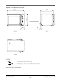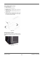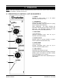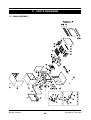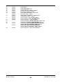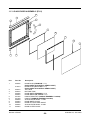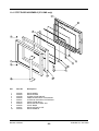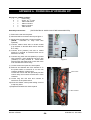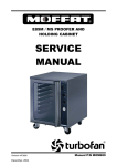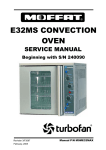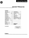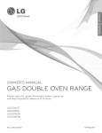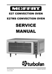
1
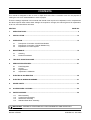
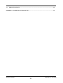
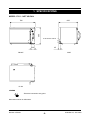
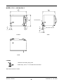
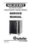
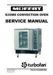
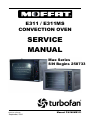
E311 / E311MS
CONVECTION OVEN
SERVICE
MANUAL
Max Series
S/N Begins 258733
Revision 4/F3535
September, 2004
Manual P/N M0ME311
WARNING: ALL INSTALLATION AND SERVICE REPAIR WORK MUST BE CARRIED OUT BY
QUALIFIED PERSONS ONLY.
Revision 4/F3535
-2-
© Moffat Ltd, June 2004
CONTENTS
This manual is designed to take a more in depth look at the E311 convection oven for the purpose of
making the unit more understandable to service people.
There are settings explained in this manual that should never require to be adjusted, but for completeness
and those special cases where these settings are required to change, this manual gives a full explanation
as to how, and what effects will result.
SECTION
PAGE NO.
1.
SPECIFICATIONS ........................................................................................................................... 5
2.
INSTALLATION............................................................................................................................. 10
3.
OPERATION.................................................................................................................................. 12
3.1
3.2
3.3
4.
Description of Controls—Not US/Can Models
Description of Controls—US/Can Models Only
Explanation of Control System
MAINTENANCE ............................................................................................................................ 16
4.1
4.2
Cleaning
Routine Procedures
5.
TROUBLE SHOOTING GUIDE ..................................................................................................... 18
6.
SERVICE PROCEDURES ............................................................................................................. 21
6.1
6.2
6.3
6.4
Fault Diagnosis
Access
Replacement
Adjustment / Calibration
7.
ELECTRICAL SCHEMATICS ....................................................................................................... 39
8.
ELECTRICAL WIRING DIAGRAMS ............................................................................................. 41
9.
SPARE PARTS ............................................................................................................................. 43
10.
ACCESSORIES / OPTIONS.......................................................................................................... 45
11.
PARTS DIAGRAM......................................................................................................................... 46
11.1
11.2
11.3
11.4
Main Assembly
Control Panel Assembly
Glass Door Assembly
Stainless Steel Door Assembly
IMPORTANT: MAKING ALTERATIONS MAY VOID WARRANTIES AND APPROVALS.
Revision 4/F3535
-3-
© Moffat Ltd, June 2004
12.
SERVICE CONTACTS .................................................................................................................. 54
APPENDIX A. POWER RELAY UPGRADE KIT.................................................................................... 56
Revision 4/F3535
-4-
© Moffat Ltd, June 2004
1. SPECIFICATIONS
MODEL: E311 - NOT US/CAN
600
580
796
ELECTRICAL ENTRY
1
E
1
120
E
45
SIDE
FRONT
1
E
PLAN
LEGEND
- Electrical connection entry point
Dimensions shown in millimetres.
Revision 4/F3535
-5-
© Moffat Ltd, June 2004
MODEL: E311 - US/CAN ONLY
3"
318
7"
228
5"
238
15
8"
WATER ENTRY
5"
8
43
4"
ELECTRICAL ENTRY
13
4"
SIDE
FRONT
PLAN
LEGEND
- Electrical connection entry point
- Water entry - 9mm / 3/8” I.D male hose connection
Dimensions shown in inches.
Revision 4/F3535
-6-
© Moffat Ltd, June 2004
MODEL: E311MS NOT US/CAN
600
580
796
ELECTRICAL ENTRY
1
E
1
120
E
45
FRONT
SIDE
1
E
PLAN
LEGEND
- Electrical connection entry point
- Water entry - 9mm / 3/8” I.D male hose connection
Dimensions shown in millimetres.
Revision 4/F3535
-7-
© Moffat Ltd, June 2004
MODEL: E311MS - US/CAN ONLY
313
8"
227
8"
235
8"
15
8"
WATER ENTRY
5"
8
43
4"
ELECTRICAL ENTRY
13
4"
SIDE
FRONT
PLAN
LEGEND
- Electrical connection entry point
- Water entry - 9mm / 3/8” I.D male hose connection
Dimensions shown in inches.
Revision 4/F3535
-8-
© Moffat Ltd, June 2004
LOCATION
To ensure correct ventilation for the motor and
controls the following minimum installation
clearances are to be adhered to:
Top
Rear
Left-hand side
Right-hand side
200mm / 8”
25mm / 1”
25mm / 1”
25mm / 1”
OVEN INTERNAL DIMENSIONS
Width
Height
Depth
Oven Volume
544 mm / 21.4”
418 mm / 16.5”
432 mm / 17”
0.12 m³ / 4.25 ft³
OVEN RACK SIZE
Width
Depth:
530 mm / 20 7/8”
370 mm / 14 1/2”
ELECTRICAL SUPPLY SPECIFICATION
OPTIONS
208 V AC 60 Hz, 14.6 A, 3.2kW @ 208 V
220-240 V AC 60 Hz, 13.0 A, 3.1kW @ 240 V
208-220 V AC 50 Hz, 14.6 A, 3.2kW @ 220 V
230-240 V AC 50 Hz, 13.0 A, 3.1kW @ 240 V
ELECTRICAL PLUG SPECIFICATION
REQUIREMENTS
Australia
3-pin 250V 15A, AS/NZ 3112
Canada
3-pin 250V 15A, NEMA 6-15
New Zealand 3-pin 250V 15A, AS/NZ 3112
United Kingdom 3-pin 250V 13A fused, BS 1363A
United States 3-pin 250V 15A, NEMA 6-15
Other Countries 3-pin 250V 13A minimum, type
to meet country standards
WATER SUPPLY CONNECTION
(US/CAN ONLY)
Max Pressure 550 kPa / 5.5 bar / 80 psi
Min Pressure 100 kPa / 1.0 bar / 15 psi
Revision 4/F3535
-9-
© Moffat Ltd, June 2004
2. INSTALLATION
WARNING: THIS APPLIANCE MUST BE GROUNDED.
WARNING: ALL INSTALLATION AND SERVICE REPAIR WORK MUST BE CARRIED OUT BY
QUALIFIED PERSONS ONLY.
DOUBLE STACKING UNITS
It is most important that the oven is installed
correctly and that the operation is correct
before use. Installation shall comply with local
electrical, health and safety requirements.
When it is desired to mount one unit on top of
another the 31mm (1¼") high spacer feet must be
used. These short feet should be screwed on,
and the unit lifted on top of the bottom unit, where
it locates safely under its own weight, for normal
applications.
BEFORE CONNECTION TO THE POWER
SUPPLY
Unpack and check unit for damage and report
any damage to the carrier and dealer. Report
any deficiencies to your dealer. Fit the feet which
are packed inside the oven. Fit door handle to
oven door. Check that the available power
supply is correct to that shown on the rating plate
located on the right-hand side panel (refer figure
2.3).
BEFORE USE
Operate the oven for about 1 hour at 200°C (400°
F) to remove any fumes or odours which may be
present.
ELECTRICAL CONNECTION
E311 convection ovens are supplied with
pre-fitted cords. Ensure unit is fitted with the
correct cord and plug for the installation (refer
specifications section).
208 V AC 60 Hz, 14.6 A, 3.2kW @ 208 V
220-240 V AC 60 Hz, 13.0 A, 3.1kW @ 240 V
208-220 V AC 50 Hz, 14.6 A, 3.2kW @ 220 V
230-240 V AC 50 Hz, 13.0 A, 3.1kW @ 240 V
L1
Phase
LOCATION
RED
BROWN
BLACK
To ensure correct ventilation for the motor and
controls the following minimum installation
clearances are to be adhered to:
L2
Ground
Neutral
BLACK
BLUE
WHITE
GREEN
GREEN/YELLOW
WARNING: THIS APPLIANCE MUST
BE GROUNDED / EARTHED
Top
Rear
Left-hand side
Right-hand side
200mm / 8”
25mm / 1”
25mm / 1”
25mm / 1”
Figure 2.1
Should changing of the cord be necessary, gain
access to the electrical connection terminal block
and strain relief by removing the back panel (four
screws).
IMPORTANT: THE OVEN VENT
LOCATED ON THE CABINET TOP MUST
NEVER BE OBSTRUCTED.
WATER CONNECTION - US/CAN ONLY
Position the oven in its allocated working
position. Use a spirit level to ensure the oven is
level from side to side and front to back. (If this is
not carried out, uneven cooking could occur).
The feet/legs used with bench or floor mounting
or provided with stands are adjustable and will
require adjusting in levelling the unit. It should be
positioned so the operating panel and oven
shelves are easily reachable for loading and
unloading.
A cold water supply should be fitted to the
water inlet (9mm / 3/8” hose connection) which is
located on the rear of the left hand side of the
unit.
Connect water supply - Max inlet pressure 80psi /
550kPa.
Turn on water supply to check for leaks.
IMPORTANT: MAXIMUM INLET WATER
PRESSURE IS 550 kPa / 80 psi.
Revision 4/F3535
-10-
© Moffat Ltd, June 2004
DOOR HANDLE INSTALLATION
1. Open oven door.
2. Remove two screws (item 2).
3. Remove the two screws (item 3) from the
handle (item 1).
4. Install the handle bracket through the slot on
the door side.
5. Screw in the two screws (item 2) fully, then
fully screw in the previous two screws (item
3). Ensure that they are tight.
1
3
2
Figure 2.2
RATING PLATE LOCATION
The rating plate for the E311 convection oven is
located at the bottom left corner of the RH side
panel.
Rating Plate
Figure 2.3
Revision 4/F3535
-11-
© Moffat Ltd, June 2004
3. OPERATION
NOTE: A full user’s operation manual is supplied with the product and can be used for further referencing
of installation, operation and service.
3.1 DESCRIPTION OF CONTROLS—NOT US/CAN MODELS
1. POWER
Depress to switch power on or off (switch
illuminates when power is on).
2. THERMOSTAT
Temperature range 50 - 280°C.
Indicator illuminates when elements are cycling
ON to maintain set temperature.
1
GRILL POSITION - The GRILL indicator will
illuminate indicating that the GRILL function has
been set. The HEATING indicator will also
illuminate whenever the elements are on.
2
3. BAKE TIMER
1 Hour bake timer.
(Indicator illuminates when “time up” (0) is
reached, and buzzer sounds).
4. ROAST N HOLD
Depress switch to activate ’ROAST N HOLD’
function (Switch illuminates when ON).
3
5. ROAST TIMER
3 Hour roast timer.
Indicator illuminates when “time up” (0) is
reached, and product held at 75°C.
4
6. LIGHT SWITCH
Push switch to activate oven light.
(Light illuminates while button latched in the down
position) (From S/N 258733 “E311MS” models)
(From S/N 260862 “E311” models).
5
(Light illuminates while button depressed) (Up to
S/N 260861).
6
Revision 4/F3535
-12-
© Moffat Ltd, June 2004
3.2 DESCRIPTION OF CONTROLS—US/CAN MODELS ONLY
1. POWER
Depress to switch power on or off (switch
illuminates when power is on).
2. THERMOSTAT
Temperature range 120 - 550°F.
Indicator illuminates when elements are cycling
ON to maintain set temperature.
1
BROIL POSITION - The BROIL indicator will
illuminate indicating that the BROIL function has
been set. The HEATING indicator will also
illuminate whenever the elements are on.
2
3. BAKE TIMER
1 Hour bake timer.
(Indicator illuminates when “time up” (0) is
reached, and buzzer sounds).
4. ROAST N HOLD
Depress switch to activate ’ROAST N HOLD’
function (Switch illuminates when ON).
3
5. ROAST TIMER
3 Hour roast timer.
Indicator illuminates when “time up” (0) is
reached, and product held at 167°F.
4
6. STEAM SWITCH
Push switch to activate water injection (Water
injects into oven while the button is depressed).
7. LIGHT SWITCH
5
Push switch to activate oven light.
(Light illuminates while button latched in the down
position) (From S/N 258733 “E311MS” models)
(From S/N 260862 “E311” models).
(Light illuminates while button depressed) (Up to
S/N 260861).
6
7
Revision 4/F3535
-13-
© Moffat Ltd, June 2004
3.3
steam button will close the solenoid valve. This
feature is used to instantaneously add moisture
into the oven cavity, or to introduce a reservoir of
water in the water trough to maintain humidity in
the oven chamber and minimise product’s
moisture loss during cooking.
EXPLANATION OF CONTROL
SYSTEM
The E311 Turbofan convection oven features
multi-function operator controls for which a
correct understanding of their operation is
required before carrying out any service or fault
repair work. The control device functions are
explained as follows:
For units manufactured from serial number
232054, power to the temperature control circuit
and elements is supplied via a power relay
located near the terminal block at the rear of the
unit. Although the power relay has two poles with
changeover contacts, only the normally closed
contact on one pole is used - the other is
redundant. When the power switch on the control
panel is switched on the power relay is energised
and the normally open contact is closed,
providing power to the temperature control circuit.
A power switch on the control panel isolates all
power to the controls of the oven. With the power
switch Off all functions of the oven are
inoperable.
NOTE: The supply voltage is fed directly to the
input side of the power relay whenever the
electrical supply is on.
The temperature control of this oven is with a
capillary type thermostat which can be set to a
required cooking temperature, or set to the Grill/
Broil position to provide top browning or grilling/
broiling in the oven.
With the power switch On (illuminated) power is
directly supplied to the 60 minute bake timer,
steam (water injection) switch, door microswitch,
light switch, and the hold switch circuit. (On units
manufacture prior to serial number 232053 power
is also supplied directly to the temperature control
circuit). Accordingly the oven circulation fan will
operate when the door is closed, and with door
open the oven light will come on and the circulation fan will shut down, as these are controlled via
the door microswitch. The control panel light
switch will turn the oven light on when the door is
closed. On units from S/N 260862 the switch is
latching and will activate the light while latched in
the down position. On units prior to S/N 260861
the switch is momentary and will need to be held
in to activate the light.
The thermostat switch has a separate switch
body assembled onto the front from the shaft
assembly and when the thermostat is set to a
cooking temperature, one set of contacts is
closed to switch power from the oven thermostat
to the bottom heating element in the oven. The
second switch contact of this switch assembly
remains open in this setting and isolates power
from the top element inner coil. The top element
outer coil is directly switched on from the oven
thermostat. Accordingly only the top outer
element and the bottom element are used when a
cooking temperature is selected. The control
panel indicator light above the thermostat knob
cycles On and Off with the thermostat to indicate
when the elements are on and the oven is
heating.
The 60 minute timer is a mechanical timer and
can therefore be operated with the oven’s power
switch On or Off. However, only with the oven’s
power switch On will the switch contacts of the 60
minute timer turn on the time-up buzzer and
illuminate the time-up indicator on the control
panel. The buzzer and time-up indicator provide
indication that the time setting has run down to
zero and at this point will remain On continuously
until the 60 minute timer has been manually set
back to the Off (vertical) position. The 60 minute
timer does not control any other part of the oven’s
operating system as this timer is independent of
the temperature control and heating system.
When the thermostat control is set to the Grill
position the first switch contact opens and the
second switch contact closes. This arrangement
allows power to be provided to the top element
inner coil when the thermostat is On, and isolates
power from going to the bottom heating element.
The top element outer coil which is directly fed
from the oven thermostat switch is therefore On
in conjunction with the top element inner coil
when the thermostat is set to the Grill position.
As both the top inner and outer element coils are
thermostatically controlled, the elements will cycle
On/Off with the door closed as the thermostat
setting in the Grill position is 300°C (600°F). If the
Grill position is selected with the door open, the
elements will remain On continuously and the
US/Canada only: The steam (water injection)
switch on the control panel can be operated
whenever the power switch is On. The switch is
momentary and when depressed, will operate the
electric solenoid valve at the rear of the oven and
inject water into the water trough at the bottom of
the left hand side rack in the oven. Releasing the
Revision 4/F3535
-14-
© Moffat Ltd, June 2004
circulation fan will be turned Off. The control
panel Grill indicator will illuminate when the
thermostat is set to the Grill position and will cycle
On and Off with the main heating indicator light.
over to their normally closed position which
isolates power from the timer motor and the oven
thermostat. It also switches power back to the
oven hold thermostat.
At this point the
temperature control is now maintained by the
hold thermostat as previously described. To
cancel the hold circuit the Roast-and-Hold switch
is turned Off. This turns off the contactor which
removes power from the 3 hour timer and closes
the contactor pole on the contactor that feeds the
main oven thermostat.
The E311 Turbofan convection oven features a
Roast-and-Hold system which can be used to
automatically set the oven to a fixed holding
temperature at the end of a timed cooking period.
From serial number 232054: When the Roastand-Hold switch is turned On the switch will
illuminate and turn on a relay found on the inside
of the control panel. (This relay has two poles
with changeover contacts, but only one pole is
used). When this relay is switched On the
normally closed contact opens, isolating the
normal power supply to the oven thermostat and
the normally open contact closes supplying power
to the 3 hour roast timer.
To serial number 232053: When the Roast-andHold switch is turned On the switch will illuminate
and turn on a mini-contactor found on the inside
of the control panel. When this relay is switched
On a normally closed switch pole on the contactor
is open and the normal power supply to the oven
thermostat is isolated. A second normally open
switch pole is closed and this provides power to
the 3 hour roast timer.
The factory preset hold thermostat can be
adjusted as required to change the holding
temperature if necessary. Refer Service section
for this procedure.
The following Troubleshooting Guide should be
used to identify any incorrect oven operation. On
correct identification of the operating fault the
Troubleshooting Guide will make reference to the
corrective action required, or refer to the Fault
Diagnosis section and/or Service section to assist
in correction of the fault.
If the roast timer is in the Hold (vertical) position
the timer switch contacts will be in their normally
closed position and supply power directly to the
Hold thermostat located behind the control panel.
The Hold thermostat is factory set to 75°C (167°
F) and will directly supply power to the bottom
heating element as required to maintain its preset
temperature.
If the main thermostat is turned On, power will
also be supplied to the top outer element coil
through the first switch contact of the thermostat
front switch assembly.
In this case the
thermostat heating light will also cycle On/Off as
the Hold thermostat maintains temperature.
In the Roast-and Hold mode the 3 hour timer can
be set to a selected roasting time. During this
time period the normally open switch contacts of
the timer are closed. The timer has two change
over switches and in this position one is used to
supply power to its timing motor and the other is
used to switch power directly to the main oven
thermostat. During the 3 hour timer run-down
period the oven temperature will be controlled by
the main oven thermostat to the set temperature
and operate as previously described.
When the 3 hour timer has run down and reached
the Hold position the two switch contacts change
Revision 4/F3535
-15-
© Moffat Ltd, June 2004
4. MAINTENANCE
WARNING: ALL INSTALLATION AND SERVICE REPAIR WORK MUST BE CARRIED OUT BY
QUALIFIED PERSONS ONLY.
OVEN SEALS
4.1 CLEANING
To remove, hold at their centre point and pull
forward until they unclip. Remove side seals first,
then top and bottom. The seals may be washed
in the sink, but take care not to cut or damage
them. To replace, ensure that the lip is facing the
oven opening. Fit the top and bottom seals first,
then the side seals.
WARNING:
ALWAYS TURN THE
POWER
SUPPLY
OFF
BEFORE
CLEANING.
IMPORTANT:
THIS UNIT IS NOT
WATER PROOF.
DO NOT USE A WATER JET SPRAY TO
CLEAN INTERIOR OR EXTERIOR OF THIS
UNIT.
OVEN DOOR GLASS
Clean with conventional glass cleaners
EXTERIOR
Clean with a good quality stainless steel cleaning
compound.
Harsh abrasive cleaners may
damage the surface.
INTERIOR
Ensure that the oven chamber is cool. Do not use
wire brushes, steel wool or other abrasive
materials. Clean the oven regularly with a good
quality oven cleaner. Take care not to damage
the fan or the tube at the right side of the oven
which controls the thermostat.
OVEN RACKS
To remove, slide out to the stop position, raise
the front edge up, and lift out.
SIDE RACKS
Undo the thumbscrew (anti-clockwise rotation)
securing rack to oven wall, swing rack towards
centre of oven to disengage location pin at front
of side, and pull rack forward to remove. To
replace, engage rack in rear holes, swing towards
side of oven to engage in front hole, and replace
thumbscrew.
FAN BAFFLE
To remove, unscrew the oven lamp glass and lift
the baffle out. To replace, locate the bottom edge
of the baffle over the bottom element terminal
plate and secure in place with the oven lamp
glass.
IMPORTANT: DO NOT OVER- TIGHTEN
THE LAMP GLASS.
Revision 4/F3535
-16-
© Moffat Ltd, June 2004
4.2 ROUTINE PROCEDURES
PROCEDURE
INTERVAL
DOOR SEALS
Check for deterioration.
12 months
DOOR PIVOT BUSHES
Check for wear.
12 months
DOOR CATCH
Ensure that catch is adjusted such that the door closes 12 months
properly.
ELEMENTS
Check that element resistances are correct to their rating 12 months
(refer 6.3.13)
WATER NOZZLE
(US/CAN ONLY)
Check for liming / scale build-up in water nozzle.
Revision 4/F3535
-17-
12 months
© Moffat Ltd, June 2004
5. TROUBLE SHOOTING
WARNING: ALL INSTALLATION AND SERVICE REPAIR WORK MUST BE CARRIED OUT BY
QUALIFIED PERSONS ONLY.
FAULT
THE OVEN DOES NOT
OPERATE / START
FAN DOESN’T OPERATE
OVEN LIGHT NOT
ILLUMINATING - DOOR OPEN
POSSIBLE CAUSE
REMEDY
The mains isolating switch on the
wall, circuit breaker or fuses are
“off” at the power board.
Turn on.
The power switch on the oven is
off.
Depress switch. Switch will
illuminate.
Incorrect electrical supply.
(Refer fault diagnosis 6.1.1)
Ensure electrical supply correct.
Power switch on unit faulty.
(Refer fault diagnosis 6.1.1)
Replace.
(Refer service section 6.3.4)
Door not closed.
(Fan only operates with door
closed).
Close door.
Door microswitch out of
adjustment.
(Refer fault diagnosis 6.1.2)
Adjust.
(Refer service section 6.4.2)
Door microswitch faulty
(Refer fault diagnosis 6.1.2)
Replace.
(Refer service section 6.3.2)
Fan motor faulty.
(Refer fault diagnosis 6.1.2)
Replace.
(Refer service section 6.3.18
Wiring.
Check and tighten any loose
wiring.
Blown bulb.
Replace.
(Refer service section 6.3.1)
No power to light.
(Refer fault diagnosis 6.1.3)
OVEN LIGHT NOT
Blown bulb.
ILLUMINATING - DOOR CLOSED
NO WATER INJECTION /
STEAM—US/CAN ONLY
Revision 4/F3535
Replace.
(Refer service section 6.3.1)
Light switch faulty.
(Refer fault diagnosis 6.1.4)
Replace.
(Refer service section 6.3.4)
Water not turned on.
Turn water on at water supply.
Oven water nozzle blocked.
Remove, clean or replace. (Refer
service section 6.3.15)
Fault with water valve.
(Refer fault diagnosis 6.1.5)
Service or replace as required.
(Refer service section 6.3.13,
6.3.14)
Steam switch faulty.
Replace.
(Refer service section 6.3.4)
-18-
© Moffat Ltd, June 2004
FAULT
CONTINUOUS WATER OUT OF
OVEN WATER NOZZLE—
US/CAN ONLY
POSSIBLE CAUSE
REMEDY
With oven on only—Electrical fault. Correct electrical fault.
(Refer fault diagnosis 6.1.6)
With oven on or off—Fault with
water valve.
Service or replace as required.
(Refer service section 6.3.13,
6.3.14)
60 MINUTE TIMER WILL NOT
TIME DOWN
Timer faulty.
Replace.
(Refer service section 6.3.7)
60 MINUTE TIMER
INACCURATE BELOW 20
MINUTES
Timer not set correctly.
For timer settings below 20
minutes, always rotate past 20
minutes, then back to desired
time.
Zero (time up) position not set
correctly.
(Refer service section 6.4.5
Buzzer faulty.
(Refer fault diagnosis 6.1.7)
Replace.
(Refer service section 6.3.6)
Timer not switching on buzzer.
(Refer fault diagnosis 6.1.7)
Replace.
(Refer service section 6.3.7)
60 MINUTE TIMER NO TIME UP
INDICATOR
Indicator faulty.
(Refer fault diagnosis 6.1.8)
Replace.
(Refer service section 6.3.3)
NO HEAT
Power relay faulty (From S/N
232054 only).
(Refer fault diagnosis 6.1.9)
Replace.
(Refer service section 6.3.5)
Hold relay/mini contactor faulty.
(Refer fault diagnosis 6.1.9)
Replace.
(Refer service section 6.3.11)
Thermostat faulty
(Refer fault diagnosis 6.1.9)
Replace.
(Refer service section 6.3.9)
NO TEMPERATURE
CONTROL
Thermostat faulty
(Refer fault diagnosis 6.1.10)
Replace.
(Refer service section 6.3.9)
SLOW RECOVERY
Oven in ‘Roast ‘n Hold’ mode.
Switch off ‘Roast ‘n Hold’.
Overloading of oven.
Reduce oven loading.
Electrical supply incorrect.
Check supply voltage is as per
rating plate voltage.
Fan not working.
Check fan operation.
Thermostat calibration.
(Refer fault diagnosis 6.1.11)
Correct calibration.
(Refer service section 6.4.1)
Element(s) not working.
Correct element fault.
(Refer Fault: Top element, Fault:
Bottom element)
60 MINUTE TIMER NO TIME UP
BUZZER
Revision 4/F3535
-19-
© Moffat Ltd, June 2004
FAULT
POSSIBLE CAUSE
REMEDY
BOTTOM ELEMENT NOT
WORKING
Element faulty (blown).
(Refer fault diagnosis 6.1.12)
Replace.
(Refer service section 6.3.16)
TOP ELEMENT NOT
WORKING (IN BAKE MODE—
NOT GRILL / BROIL MODE)
Element faulty / blown.
(Refer fault diagnosis 6.1.13)
Replace.
(Refer service section 6.3.16)
GRILL NOT WORKING
Element faulty / blown.
(Refer fault diagnosis 6.1.15)
Replace.
(Refer service section 6.3.16)
GRILL INDICATOR LIGHT NOT
WORKING
Indicator faulty.
(Refer fault diagnosis 6.1.16)
Replace.
(Refer service section 6.3.3)
ROAST TIMER (180 MINUTE)
WILL NOT TIME DOWN
Roast ’n’ Hold switch not
depressed.
Depress switch. Switch will
illuminate.
No power to timer / timer faulty.
(Refer fault diagnosis 6.1.17)
Correct electrical fault / replace
timer.
(Refer service section 6.3.8)
‘Roast ‘n Hold’ switch faulty.
(Refer fault diagnosis 6.1.17)
Replace.
(Refer service section 6.3.4)
Faulty indicator.
(Refer fault diagnosis 6.1.18)
Replace.
(Refer service section 6.3.3)
Faulty timer.
(Refer fault diagnosis 6.1.18)
Replace.
(Refer service section 6.3.8)
Hold thermostat set
temperature incorrect
Adjust to correct temperature.
(Refer service section 6.4.4)
Hold thermostat faulty.
(Refer fault diagnosis 6.1.19)
Replace.
(Refer service section 6.3.10)
Tray in way of door.
Correctly position tray in rack.
Door seal obstruction.
Correctly install door seal.
(Refer service section 6.3.22)
Door handle installed incorrectly.
Fit correctly.
(Refer installation section)
Door ball catch setting incorrect.
Adjust.
(Refer service section 6.4.3)
Door pivot bushes / pins worn.
Replace.
(Refer service section 6.3.23)
Door seal damaged.
Replace.
(Refer service section 6.3.22)
Door seal incorrectly fitted.
Correctly install door seal.
(Refer service section 6.3.22)
Door ball catch setting incorrect.
Adjust.
(Refer service section 6.4.3)
Door pivot bushes / pins worn.
Replace.
(Refer service section 6.3.23)
NO HOLD INDICATOR
HOLDING TEMPERATURE
INCORRECT
DOOR DOES NOT CLOSE
DOOR SEAL LEAKS
Revision 4/F3535
-20-
© Moffat Ltd, June 2004
6. SERVICE PROCEDURES
WARNING: ENSURE POWER SUPPLY IS SWITCHED OFF BEFORE SERVICING.
WARNING: ALL INSTALLATION AND SERVICE REPAIR WORK MUST BE CARRIED OUT BY
QUALIFIED PERSONS ONLY.
SECTION
6.1
FAULT DIAGNOSIS ....................................................................................................................... 23
6.1.1
6.1.2
6.1.3
6.1.4
6.1.5
6.1.6
6.1.7
6.1.8
6.1.9
6.1.10
6.1.11
6.1.12
6.1.13
6.1.14
6.1.15
6.1.16
6.1.17
6.1.18
6.1.19
6.2
Oven Does Not Operate / Start ..................................................................................... 23
Fan Does Not Operate .................................................................................................. 23
Oven Light Not Illuminating—Door Open...................................................................... 23
Oven Light Not Illuminating—Door Closed ................................................................... 23
No Water Injection / Steam—US/Can Only................................................................... 23
Continuous Water Out Of Oven Water Nozzle—US/Can Only ..................................... 24
60 Minute Timer No Time Up Buzzer............................................................................ 24
60 Minute Timer No Time Up Indicator ......................................................................... 24
No Heat ......................................................................................................................... 24
No Temperature Control ............................................................................................... 25
Slow Recovery .............................................................................................................. 25
Bottom Element Not Working........................................................................................ 25
Top Element Not Working (In Bake Mode—Not Grill / Broil)......................................... 26
No Thermostat Heating Indicator .................................................................................. 26
Grill Not Working ........................................................................................................... 26
Grill Indicator Not Working ............................................................................................ 26
Roast Timer (180 Minute) Will Not Time Down............................................................. 26
No Hold Indicator .......................................................................................................... 27
Holding Temperature Incorrect ..................................................................................... 27
ACCESS ......................................................................................................................................... 28
6.2.1
6.2.2
6.2.3
6.2.4
6.3
PAGE NO.
Control Panel................................................................................................................. 28
Service Panel (Rear Panel)........................................................................................... 28
Baffle ............................................................................................................................. 28
Control Panel (Rear) ..................................................................................................... 28
REPLACEMENT............................................................................................................................. 29
6.3.1
6.3.2
6.3.3
6.3.4
6.3.5
6.3.6
6.3.7
6.3.8
6.3.9
6.3.10
6.3.11
6.3.12
6.3.13
6.3.14
6.3.15
Light Bulb / Glass .......................................................................................................... 29
Door Microswitch........................................................................................................... 29
Indicator Neon Light ...................................................................................................... 29
Power / Roast / Lights / Water Switches ....................................................................... 29
Power Relay (From S/N 232054) .................................................................................. 29
Buzzer ........................................................................................................................... 30
Bake Timer.................................................................................................................... 30
Roast Timer................................................................................................................... 30
Thermostat .................................................................................................................... 30
Hold Thermostat............................................................................................................ 31
Hold Relay (From S/N 232054) ..................................................................................... 31
Mini-Contactor (To S/N 232054) ................................................................................... 31
Water Solenoid—US/Can Only ..................................................................................... 32
Water Solenoid Cleaning—US/Can Only...................................................................... 32
Spray Nozzle—US/Can Only ........................................................................................ 33
Revision 4/F3535
-21-
© Moffat Ltd, June 2004
6.3.16
6.3.17
6.3.18
6.3.19
6.3.20
6.3.21
6.3.22
6.3.23
6.3.24
6.3.25
6.3.26
6.3.27
6.4
Elements ....................................................................................................................... 33
Fan ................................................................................................................................ 33
Motor ............................................................................................................................. 33
Outer Glass (E311) ....................................................................................................... 34
Inner Glass (E311) ........................................................................................................ 34
Inner Glass Seal (E311) ................................................................................................34
Door Seals..................................................................................................................... 35
Door Pivot Bushes......................................................................................................... 35
Outer Glass (E311MS) .................................................................................................. 35
Inner Glass (E311MS)...................................................................................................35
Outer Glass Seal (E311MS).......................................................................................... 35
Inner Glass Seal (E311MS)........................................................................................... 36
ADJUSTMENT / CALIBRATION.................................................................................................... 36
6.4.1
6.4.2
6.4.3
6.4.4
6.4.5
Thermostat Calibration ..................................................................................................36
Door Microswitch Adjustment........................................................................................ 37
Door Alignment.............................................................................................................. 37
Hold Temperature Adjustment ...................................................................................... 38
60 Minute Timer Zero Position Adjustment ................................................................... 38
Revision 4/F3535
-22-
© Moffat Ltd, June 2004
6.1 FAULT DIAGNOSIS
If there is no voltage then check the electrical
connections of supply wiring.
6.1.1 OVEN DOES NOT OPERATE / START
If voltage is correct then check the oven fan for
free rotation. Remove any obstruction.
Incorrect electrical supply
If fan is free to spin and the voltage supply is correct, then the motor is faulty—replace.
Check that the voltage across phase and
neutral (L1 and L2) terminals of terminal block is
the voltage as stated on the unit’s electrical rating
plate.
6.1.3 OVEN LIGHT NOT ILLUMINATING—
DOOR OPEN
If incorrect, check electrical connection of supply
wiring and / or check electrical supply.
No power to light
Check the supply voltage across lamp housing
terminals at rear of oven. If the voltage is correct,
replace the bulb (if faulty). If the bulb is OK,
check lamp housing. Replace if faulty.
Power switch faulty
Check if power switch latches. If the switch does
not latch, then switch is faulty—replace.
If there is no voltage, open oven door and
manually depress door microswitch actuator at
top right of oven. If this activates the fan, then
the microswitch actuator arm at rear of oven
requires adjustment.
With switch latched, check voltage across
terminal one to terminal three or four. If there is
no voltage, check for fault in wiring.
Check voltage across terminal two to terminal
three or four. If there is no voltage, then switch is
faulty—replace.
NOTE:
Check voltage across micro-switch terminals to
neutral.
When power switch is latched, it should
illuminate if operating correctly.
With the door closed there should be power to the
com terminal and the n.o. terminal.
With the door open there should be power to the
com terminal and the n.c. terminal.
6.1.2 FAN DOESN’T OPERATE
If not, microswitch is faulty—replace.
Microswitch out of adjustment
Open oven door and manually depress door
microswitch actuator at top right of oven. If this
activates the fan, then the microswitch actuator
arm at rear of oven requires adjustment.
6.1.4 OVEN LIGHT NOT ILLUMINATING—
DOOR CLOSED
Light switch faulty
Microswitch faulty
Check voltage to the bottom terminal of the
switch. If there is no voltage, then check wiring.
Check voltage across microswitch terminals to
neutral.
With the door closed there should be power to the
com terminal and the n.o. terminal.
With switch depressed, check voltage at top
terminal. If there is no voltage, then replace the
switch.
With the door open there should be power to the
com terminal and the n.c. terminal.
If voltage is correct, then check wiring to light.
Alternately, perform a continuity test across the
terminals with the light switch depressed.
If not, microswitch is faulty—replace.
Microswitch
NOTE: Units from S/N 260862 use a latching
type switch.
Units up to S/N 260861 use a
momentary type switch.
com
6.1.5 NO WATER INJECTION / STEAM
(US/CANADA ONLY)
n.c.
n.o.
Fault with water valve
Figure 6.1.1
Check voltage supply across the water valve
solenoid coil with the steam switch depressed. If
there is no power supply then check the control
panel steam switch.
Fan motor faulty
Check the supply voltage across motor terminals.
Revision 4/F3535
-23-
© Moffat Ltd, June 2004
Check voltage to the bottom terminal of the
switch. If there is no voltage, then check wiring.
If no voltage at terminal 2 then timer is faulty—
replace.
With switch depressed, check for voltage at top
terminal. If there is no voltage then replace
switch.
If voltage correct, check wiring to
solenoid coil.
NOTE: Timer will continue to run for
approximately three minutes below zero.
Buzzer and time up indicator will
continue until the timer manually
switched off (to vertical position).
If the power supply to the coil is correct,
disconnect wiring to coil and check the
resistance of the coil windings.
Correct coil resistance: 2500 ohms
6.1.8 60 MINUTE TIMER NO TIME UP
INDICATOR
NOTE: If open circuit / high resistance, then the
coil is faulty—replace.
Indicator faulty
If coil resistance is correct, rewire and listen for
an audible solenoid click when the steam switch
is depressed.
With the timer in the zero position, check for
voltage across the indicator light. If correct, then
the indicator light is faulty—replace.
If solenoid can be heard functioning, and oven
water nozzle is not blocked, then remove
water solenoid and fittings and check for
blockages.
If there is no voltage then check wiring.
6.1.9 NO HEAT
Power relay faulty - From S/N 232054
Check voltage to terminal 7 on power relay (on
rear panel of oven). If there is no voltage then
check wiring to the relay.
6.1.6 CONTINUOUS WATER OUT OF OVEN
WATER NOZZLE (US/CANADA ONLY)
Water solenoid electrical fault
With control panel steam switch not
depressed, check for power supply across
solenoid coil. If there is power to the coil, then
check wiring and steam switch (refer 6.1.5).
Power
Relay
6.1.7 60 MINUTE TIMER NO TIME UP BUZZER
Figure 6.1.3
Buzzer faulty
Ensure that the power switch on the unit is turned
on, and check for voltage at terminal 4 of the
power relay. If there is no voltage at 4 then check
that the relay is energised (i.e. voltage between
terminals A and B. If not then check wiring. If
there is voltage and there is no power at terminal
4 then the relay is faulty - replace.
With timer in ‘zero’ position, check the buzzer at
top of control panel (inside) for voltage across
terminals. If voltage is correct then buzzer is
faulty—replace.
If there is no voltage, then check wiring.
Buzzer
If there is voltage at terminal 4 then check the
hold relay and the thermostat (refer below).
Buzzer Terminals
Hold relay faulty - From S/N 232054
Check voltage to terminal 1 on oven
thermostat. If there is no voltage then check
voltage at terminals 1 and 7 on hold relay (inside
control panel). If there is no voltage to terminal 7
then check wiring. If there is no voltage at
terminal 1 then check that the relay is not
energised (i.e. there should be no power between
terminals A and B on the relay). If the relay is not
energised, and there is no voltage at terminal 1
Figure 6.1.2
Timer not switching on buzzer
With timer in zero position, check voltage to top
connection (terminal 1) and bottom connection
(terminal 2) of timer. If there is no voltage at
terminal 1 then check wiring.
Revision 4/F3535
-24-
© Moffat Ltd, June 2004
then the relay is faulty - replace.
6.1.10 NO TEMPERATURE CONTROL
NOTE: The relay should only be energised when
the ’Roast ’n Hold’ switch is depressed.
Thermostat faulty
With thermostat in off (vertical) position, the
heating indicator should be off. If not then the
thermostat is faulty—replace.
If there is voltage at terminal 1 then check all
wiring to the thermostat.
Check that the thermostat phial is in correct
location and check for broken capillary tube—
replace if damaged.
B
Place an accurate digital thermometer probe in
centre of oven. Set thermostat to 180°C or
355°F. Close the oven door and allow oven
thermostat to regain temperature. If temperature
overshoots by 50°C and continues, switch off and
replace.
A
7
4
1
Figure 6.1.4
6.1.11 SLOW RECOVERY
Hold mini-contactor faulty - to S/N 232053
Thermostat out of calibration
Check voltage to terminal 1 on oven thermostat.
If there is no voltage then check voltage through
terminal 21 and 22 on mini contactor (inside
control panel). If there is no voltage to terminal
21 then check wiring. If there is no voltage to
terminal 22 then check that the contact indicator
on centre of the contactor is in ‘0’ position. If
indicator is in ‘0’ position and there is no voltage
to 21 then replace contactor.
Place an accurate digital thermometer probe in
centre of oven. Set thermostat to 180°C or 355°
F.
Close the oven door and allow oven
thermostat to cycle on and off twice. Record
oven centre temperature for the next thermostat
on and off cycle. The thermostat should cycle on
and off between 165°C and 195°C or 330°F and
385°F when set to the above temperature. If
oven temperature is outside these ranges, then
the thermostat requires recalibration.
Terminal A1
NOTE: Thermostat cycling span should be ±15°
C or 27°F
Terminal 21
Contact
Indicator
Terminal 22
6.1.12 BOTTOM ELEMENT NOT WORKING
Terminal A2
Figure 6.1.5
Element faulty (blown)
With the thermostat on and heating check voltage
across bottom element terminals at rear of oven.
If the voltage is correct then check the current
draw of element. If there is no current draw then
element is faulty—replace.
If indicator is in the ‘1’ position then check the
voltage across contactor coil terminals A1 and
A2.
NOTE: There should be no voltage across these
terminals when ‘Roast ‘n Hold’ is not
selected.
If the indicator is in position ‘1’ with no voltage
across A1 and A2 then the contactor is faulty—
replace.
Bottom Element
Terminals
Thermostat faulty
Set thermostat to 200°C or 400°F. Check the
voltage out of terminal two on the thermostat. If
there is no voltage then the thermostat is faulty—
replace.
If the voltage is correct and the heating light is on
then check all wiring to elements.
Revision 4/F3535
Figure 6.1.6
-25-
© Moffat Ltd, June 2004
If there is no voltage then check voltage is
being supplied to bottom element from terminal 6
on switch block mounted to the front of the
thermostat (fig 6.4.1). If no voltage at 6 then
check for voltage at terminal P6. If power to P6
(and none to 6), then the thermostat is faulty—
replace.
If grill indicator is illuminated, but the top inner grill
element is not functioning, check the voltage at
the top inner element coils at rear of oven. If the
voltage is correct then check current draw of
element. If there is no current draw then element
is faulty—replace.
NOTE: Top inner element current draw:
NOTE: Correct bottom element current draw:
208 V :
9.6A ± 5%
220—240V: 8.7A ± 5%
208 V:
8.7A ± 5%
220—240 V: 7.8A ± 5%
6.1.13 TOP ELEMENT NOT WORKING (IN
BAKE MODE—NOT GRILL / BROIL)
6.1.16 GRILL INDICATOR NOT WORKING
Indicator faulty
Element faulty / blown
Check the voltage across the indicator terminals.
If the voltage is correct then indicator is faulty—
replace.
NOTE: In bake mode (50—270°C or 100—550°F)
the outer coil only of the top element assembly
operates. The inner coil works only when in grill
or broil mode.
If there is no voltage then check wiring.
With thermostat on and heating check voltage
across top element terminals at rear of oven. If
voltage is correct then check current draw of the
element. If there is no current draw then the
element is faulty—replace.
6.1.17 ROAST TIMER (180 MINUTE) WILL NOT
TIME DOWN
If there is no voltage check voltage is being supplied to the top element from terminal two on the
switch block mounted to front of thermostat.
Check the voltage at terminal 5 on underside of
the 180 minute timer.
No power to timer
Check that one lead of timer motor is connected
to terminal 5 of timer and the other lead is
connected to neutral of ‘Roast ’n Hold’ switch.
If voltage is correct then check wiring.
NOTE: Top outer element current draw:
208V :
3.8A ± 5%
220—240V: 3.5A ± 5%
If voltage at terminal 5 is correct and wiring is
correct then the timer motor is faulty—replace
timer.
If there is no power at terminal 5 check for power
supply at terminal 4 of timer. If there is voltage at
terminal 4 and not at terminal 6 with timer set,
then timer switch is faulty—replace timer.
6.1.14 NO THERMOSTAT HEATING
INDICATOR
Indicator faulty
Check the voltage across the indicator terminals.
If the voltage is correct then the indicator is
faulty—replace.
If there is no voltage then check wiring.
Terminal 4
Terminal 1
6.1.15 GRILL NOT WORKING
Terminal 2
Terminal 5
Element faulty / blown
Figure 6.1.7
With thermostat in grill or broil position (fully
clockwise), check that the grill indicator on the
control panel indicates. If not, then check the
voltage at terminal P5 on the thermostat switch
(fig 6.4.1). If there is no voltage check that the
switch has power on terminal 5. If there is power
at terminal 5, but not at P5 when thermostat is in
grill position, then the switch is faulty—replace
thermostat assembly.
Revision 4/F3535
Terminal 6
Terminal 3
From Serial Number 232054:
If no voltage at terminal 4, check the relay
behind the control panel is energised (i.e.
voltage across terminals A and B). If there is
no voltage then check wiring from the hold
switch. If there is voltage then check that
there is voltage at terminal 4 and terminal 7 of
-26-
© Moffat Ltd, June 2004
the hold relay. If there is voltage at 7, but
none at 4 (and the relay is energised) then
relay is faulty - replace. If no voltage at 7 then
check wiring.
6.1.19 HOLDING TEMPERATURE INCORRECT
Hold thermostat faulty
To Serial Number 232053:
With the power switch on and illuminated, ‘Roast
‘n Hold’ switch on and illuminated, and the roast
(180 minute) timer set to hold, check that the hold
indicator is illuminated.
If no voltage at terminal 4, then check mini
contactor behind control panel is latched to the
‘1’ position. If contactor is in ‘1’ position then
check wiring.
With a cold oven (ie room temperature) check
that the top outer and bottom oven elements only
are heating. Test the voltage across the bottom
element and top element terminals at the rear of
oven. If the voltage is correct then refer Fault:
Bottom element not working (trouble shooting
section).
If contactor is in ‘0’ position when ‘Roast ‘n
Hold’ switch illuminated then check the voltage
across terminals A1 and A2 of mini contactor
(fig 6.1.3). If the voltage is correct but the
contactor in the off (‘0’) position then the
contactor is faulty—replace.
If there is no voltage across A1 and A2 then
check wiring.
NOTE: If the main thermostat is set to off
(vertical) position and ‘Roast ‘n Hold’
mode is selected, then only the bottom
element will heat.
‘Roast ‘n Hold’ switch faulty
Check if the switch latches. If the switch does not
latch then the switch is faulty—replace.
If there is no voltage at the element terminals,
check the voltage at terminal 2 (top) of the hold
thermostat at bottom rear of control panel (fig
6.3.12). If there is no voltage then check wiring.
With the switch latched, check voltage across
terminal 1 to terminal 3 or 4. If there is no voltage
then check for fault in wiring.
If the voltage is correct, and the thermostat is
adjusted above oven temperature, then check for
output voltage at terminal 1 (bottom). If there is
no voltage and the thermostat will not switch on
then the thermostat is faulty—replace.
Check voltage across terminal 2 to terminal 3 or
4. If there is no voltage then switch is faulty—
replace.
If the voltage is correct but the bottom element is
not working then check wiring.
NOTE: When the switch is latched, it should
illuminate if operating correctly.
6.1.18 NO HOLD INDICATOR
Indicator faulty
Check the voltage across the indicator terminals.
If the voltage is correct then the indicator is
faulty—replace.
If there is no voltage then check wiring.
Timer faulty
Check the voltage at terminal 3 of timer, with
timer in hold position. If the voltage is correct
then check wiring.
If there is no voltage then check voltage at
terminal 1 of timer. If there is voltage at 1, but no
voltage at terminal 3 with timer in hold
position, then timer switch is faulty—replace.
Revision 4/F3535
-27-
© Moffat Ltd, June 2004
6.2 ACCESS
6.2.3 BAFFLE
1) Remove trays, racks, element guard and left
hand side rack.
6.2.1 CONTROL PANEL
2) Undo lamp cover.
1) Open the oven door. Remove microswitch
button by pulling straight off.
Lamp
Cover
2) Undo the two screws now visible.
Microswitch
Button
Side
Rack
Two
Screws
Element
Guard
Figure 6.2.4
3) Remove baffle.
Figure 6.2.1
3) Panel is now free to hinge along right hand
side. When closing the panel ensure wires
and capillary tube are clear of metal or other
terminals.
6.2.4 CONTROL PANEL—REAR
Buzzer
Power Switch
Heating Indicator
Grill / Broil Indicator
Thermostat
Bake Time Up
Indicator
Figure 6.2.2
Bake Timer (60 minute)
6.2.2 SERVICE (REAR) PANEL
Roast‘n Hold Switch
1) Undo the four screws holding the panel.
Hold Relay / Mini Contactor
Roast ‘n Hold Time
Up Indicator
Roast Timer (180 minute)
Four
Screws
Steam Switch / Light Switch
(US/Can only) (Not US/Can)
Light Switch
(US/Can only)
Figure 6.2.3
Hold Thermostat
2) Remove panel.
Figure 6.2.5
Revision 4/F3535
-28-
© Moffat Ltd, June 2004
6.3 REPLACEMENT
Neon
Wires
6.3.1 LIGHT BULB / GLASS
1) Unscrew lamp cover.
Lamp
Cover
Figure 6.3.3
2) From back push neon through front of panel
rotating clockwise.
3) Push new neon in from front of panel, and
reconnect wires.
6.3.4 POWER / ROAST / LIGHTS / WATER
SWITCHES
Figure 6.3.1
2) Unscrew bulb out of fitting.
1) With control panel open (refer 6.2.1)
remove the wires from the back of the switch,
noting their positions.
3) Screw in replacement bulb.
4) Ensure seal fitted. Screw lamp cover into
holder with baffle fitted (do not over tighten).
Switch
Wires
6.3.2 DOOR MICROSWITCH
1) Remove service panel (refer 6.2.2).
2) Remove two screws holding microswitch to
bracket.
Figure 6.3.4
2) From back push switch through front of panel.
3) Push new switch in from front of panel, and
reconnect wires.
Two Screws
6.3.5 POWER RELAY (FROM S/N 232054)
1) Remove service panel (refer 6.2.2).
2) Remove the two screws securing the relay to
the rear panel.
Figure 6.3.2
3) Transfer wires to new micro-switch and
re-assemble.
Power
Relay
4) Adjust microswitch (refer 6.4.2).
6.3.3 INDICATOR NEON LIGHT
Figure 6.3.5
1) With control panel open (refer 6.2.1) remove
the wires from the back of the neon.
Revision 4/F3535
3) Transfer the wires to the new relay.
4) Secure the relay to the rear panel with two
screws and replace the service panel.
-29-
© Moffat Ltd, June 2004
6.3.6 BUZZER
6.3.8 ROAST TIMER
1) Remove control panel (refer 6.2.1).
1) Remove roast timer knob by pulling it firmly
away from control panel.
2) Remove two screws holding buzzer bracket
to panel.
2) Open control panel (refer 6.2.1) and undo two
screws securing timer.
Two Screws
Two Screws
Figure 6.3.9
3) Transfer wires to new timer.
Figure 6.3.6
4) Withdraw old timer and insert new timer,
securing with screws.
3) Withdraw and remove two screws holding
buzzer to bracket.
5) Replace knob.
6.3.9 THERMOSTAT
1) Pull knob off front of thermostat
Two
Screws
2) Open control panel (refer 6.2.1) and undo two
screws securing thermostat.
Figure 6.3.7
Two Screws
4) Transfer wires to new buzzer.
5) Reassemble in reverse order.
6.3.7 BAKE TIMER
1) Remove bake timer knob by pulling it firmly
away from control panel.
Figure 6.3.10
3) Transfer wires to new thermostat.
2) Open control panel (refer 6.2.1) and undo two
screws securing timer.
4) Remove service panel (refer 6.2.2) and from
inside of oven loosen two screws holding
thermostat phial bracket.
Two Screws
Two
Screws
Figure 6.3.8
Figure 6.3.11
3) Transfer wires to new timer.
4) Withdraw old timer and insert new timer,
securing with screws.
5) Replace knob.
Revision 4/F3535
-30-
© Moffat Ltd, June 2004
5) Withdraw old thermostat phial through rear of
oven.
6.3.11 HOLD RELAY (FROM S/N 232054)
6) Remove fibreglass sleeve from old thermostat
and fit it to replacement thermostat.
1) Open control panel (refer 6.2.1) and
transfer wires from old hold relay to new
relay.
2) Remove two screws securing the old hold
relay to control panel.
7) Insert new thermostat.
Fibreglass Sleeve
Thermostat Phial
Figure 6.3.12
Hold Relay
8) Re-assemble in reverse order.
Figure 6.3.15
6.3.10 HOLD THERMOSTAT
3) Secure new hold relay to the control panel
using two screws.
1) Open control panel (refer 6.2.1) and undo two
screws securing hold thermostat bracket.
6.3.12 MINI-CONTACTOR (TO S/N 232053)
1) Open control panel (refer 6.2.1) and transfer
wires from old mini-contactor to new
contactor.
2) Remove two screws securing old minicontactor to control panel.
Two Screws
Two Screws
Figure 6.3.13
2) Transfer wires to new thermostat.
Figure 6.3.16
3) Remove service panel (refer 6.2.2) and from
inside of oven loosen the thermostat phial
bracket.
3) Secure new mini-contactor to control panel
using two screws.
Two
Screws
Figure 6.3.14
4) Withdraw old thermostat phial through rear of
oven.
5) Insert new thermostat.
6) Re-assemble in reverse order.
Revision 4/F3535
-31-
© Moffat Ltd, June 2004
6.3.13 WATER SOLENOID (US/CAN ONLY)
6.3.14 WATER SOLENOID CLEANING
(US/CAN ONLY)
1) Ensure water supply is turned off.
Units manufactured from S/N 258733
2) Inside the oven remove the baffle (refer
6.2.3), then unscrew the water injection
nozzle.
1) Disconnect water supply from the water
solenoid.
2) Remove the sieve from the water valve
assembly by pulling firmly away from the
assembly with a pair of pliers.
Water Injection
Nozzle
Sieve
Figure 6.3.17
3) With the service panel removed (refer 6.2.2)
remove the wires from the solenoid.
Figure 6.3.15
4) Disconnect hose fitting.
4) Clean the sieve, removing all dirt and grime.
5) Unscrew the three screws holding solenoid
bracket to the rear of unit and remove valve
assembly.
5) Replace the sieve and reconnect the water
supply.
Units manufactured up to S/N 258732
1) Remove water solenoid (refer 6.3.13).
2) Remove the two screws securing the bracket
to the solenoid.
Figure 6.3.18
Three Screws
Two Screws
6) On suitable work surface, remove brass
piping connections (1/2” spanner) and two
screws (on bracket) and extract solenoid.
Figure 6.3.20
3) Remove the valve assembly.
Two
Screws
Brass
Connections
Valve Assembly
Figure 6.3.21
Figure 6.3.19
4) Clean the valve assembly, removing all dirt
and grime from the valve seat.
5) Reassemble the valve assembly and
solenoid.
7) Secure new solenoid with screws, and
re-assemble. Check that flow direction as
marked on valve is correct (flow into spray
nozzle).
Revision 4/F3535
-32-
© Moffat Ltd, June 2004
6.3.15 SPRAY NOZZLE (US/CAN ONLY)
6.3.17 FAN
1) Inside the oven remove the LH side rack and
baffle (refer 6.2.3), then unscrew the water
injection nozzle.
1) With service panel and baffle removed (refer
6.2.2 and 6.2.3) undo the centre nut.
NOTE: LH thread - Turn clockwise to loosen.
Water Injection
Nozzle
Centre Nut
Figure 6.3.22
2) Clean or replace as required, ensuring debris
free on re-assembly.
Figure 6.3.24
2) Replace and re-assemble in reverse order.
6.3.16 ELEMENTS
6.3.18 MOTOR
1) With service panel and baffle removed (refer
6.2.2 and 6.2.3) remove the wires from the
element(s).
1) Remove fan (refer 6.3.17) and then remove
the wires that go to the motor.
2) Undo the four screws holding the motor
bracket in place (from the outside) and
remove motor assembly.
2) Unscrew the element from inside the oven.
Screws (4)
Top Element
One Screw
60 Hz
Terminal
Neutral
50 Hz
Terminal
Earth /
Ground
Bottom Element
Two Screws
Figure 6.3.25
Figure 6.3.23
3) Remove three screws holding motor to
bracket and remove motor.
3) Pull element carefully to remove.
4) Replace and re-assemble in reverse order.
Element Ratings ±5%
208 V
220 - 240V
Top Inner Element
24.5 ohms
Top Outer Element
55.3 ohms
Bottom Element
22.5 ohms
Top Inner Element
29.5 ohms
Top Outer Element
66.5 ohms
Bottom Element
27.3 ohms
Three Screws
Figure 6.3.26
4) Replace and re-assemble in reverse order.
5) Ensure wire connections are correct to the
voltage supply—60 Hz / 50 Hz (fig 6.3.23)
Revision 4/F3535
-33-
© Moffat Ltd, June 2004
Two
Screws
6.3.19 OUTER GLASS (E311)
1) Open door
2) Undo two screws securing Turbofan cover
plate to oven, and remove cover plate.
Two Screws
Figure 6.3.30
6) Lift outer glass away from door.
7) To replace, ensure that the two silicone
rubber seals are in place on the left hand and
right hand side of the door frame. Clean the
inside of the glass and refit it, ensuring that
the silicone rubber seals cover the outer
edges of the glass. Refit the bottom trim.
2 Screws
Figure 6.3.27
3) Remove LH screw whilst supporting the door.
Lift bracket and remove door from oven.
6.3.20 INNER GLASS (E311)
1) Remove the outer glass as above. Uncrimp
the retaining lugs of the window spacer and
remove the spacer and glass.
LH Screw
Retaining
Lugs
Figure 6.3.28
4) Remove screws securing door handle.
Figure 6.3.31
Screws
2) To replace, ensure the silicone rubber seal
has not been displaced. Clean the glass and
refit it. Place the window spacer in position
and crimp the retaining lugs over to hold the
glass in place. Refit outer glass as above.
Figure 6.3.29
6.3.21 INNER GLASS SEAL (E311)
5) Remove two screws in top trim and two
screws in bottom trim of door, and remove
trim panels.
1) Remove the door inner glass (refer 6.3.20).
2) The inner glass seal can now be removed and
replaced.
NOTE: When fitting new seal, ensure join is at
top of door.
Revision 4/F3535
-34-
© Moffat Ltd, June 2004
3) Place door on bench with door outer facing
up. Lift door outer up removing it from door
assembly. Remove outer glass.
6.3.22 DOOR SEALS
1) Open oven door.
2) To remove, hold at their centre point and pull
forward until they unclip
4) To replace, clean inner and outer glass,
ensure the silicone rubber seal has not been
displaced and refit door outer. Reassemble in
reverse order.
5) Reinstall door by reversing steps one to three
of section 6.3.19.
6.3.25 INNER GLASS (E311MS)
Figure 6.3.32
1) Remove outer glass as per steps one to three
of section 6.3.23
Door Seals
2) Uncrimp the retaining tags and remove glass
clamp.
3) Refit new seals.
Note: Fit top and bottom seals first, with the open
side of the seal facing downwards. Fit side
seals with open side facing outwards.
3) Remove inner glass.
4) To replace, ensure the silicone rubber seal
has not been displaced. Clean the glass and
refit it. Place the glass clamp in position and
crimp the retaining tags over to hold the glass
in place. Refit outer glass as above.
6.3.23 DOOR PIVOT BUSHES
Door Inner
1) Remove door as per steps one to three of
section 6.3.19.
Door Glass
2) Door bushes can now be removed and
replaced.
Door Outer
3) Reinstall door by reversing steps one to three
of section 6.3.19.
6.3.24 OUTER GLASS (E311MS)
1) Remove door as per steps one to three of
section 6.3.19.
2) Remove door bushes, catch plate (4 screws),
handle (4 screws), top and bottom screws (4).
Inner Seal
Glass Clamp
Top Door
Screws
Outer Seal
Figure 6.3.34
Door Pivot
Bushes
Door Catch
Plate
(4 screws)
6.3.26 OUTER GLASS SEAL (E311MS)
1) Remove the door outer glass (refer 6.3.24).
2) The outer glass seal can now be removed
and replaced.
Bottom Door
Screws
NOTE: When fitting new seal, ensure join is at
top of door.
Door Handle
(4 screws)
Figure 6.3.33
Revision 4/F3535
-35-
© Moffat Ltd, June 2004
6.4 ADJUSTMENT / CALIBRATION
6.3.27 INNER GLASS SEAL (E311MS)
1) Remove the door inner glass (refer 6.3.25).
2) The inner glass seal can now be removed and
replaced.
6.4.1 THERMOSTAT CALIBRATION
NOTE: When fitting new seal, ensure join is at
top of door.
IMPORTANT:
IF
THE
OVEN
TEMPERATURE NEEDS TO BE INCREASED,
ENSURE THAT THE THERMOSTAT IS IN THE
‘OFF’ POSITION BEFORE CARRYING OUT
ADJUSTMENT.
IF OVEN TEMPERATURE NEEDS TO BE
DECREASED, ENSURE THERMOSTAT IS IN
THE ‘MAX’ TEMPERATURE POSITION
BEFORE CARRYING OUT ANY ADJUSTMENT.
Calibration Nut
Thermostat Shaft
Grill/Broil Switch
Thermostat
Figure 6.4.1
1) Turn off power.
2) Remove thermostat knob by pulling it firmly
away from control panel.
3) Open control panel (refer 6.2.1). Remove two
screws on control panel holding thermostat.
Screws
Figure 6.4.2
4) The thermostat can now be removed.
Revision 4/F3535
-36-
© Moffat Ltd, June 2004
Thermostat
6.4.2 DOOR MICROSWITCH ADJUSTMENT
1) Open oven door.
2) Remove service panel (refer 6.2.2).
3) With fingers, bend actuator arm of
microswitch so that switch operates when
door is in closed position.
Actuator Arm
Figure 6.4.3
5) Carefully remove two screws holding Grill/
Broil switch to thermostat.
HINT: Tape Grill/Broil switch assembly
together before removal to prevent it from
springing apart.
Screws
Figure 6.4.6
6.4.3 DOOR ALIGNMENT
Grill/Broil
Switch
1) Alignment of the door can be achieved by
loosening the two hex head bolts securing the
bottom plate to the oven body. The plate may
now be moved sideways or in / out to achieve
correct door alignment. (Door should be
parallel to bottom plate and touching oven
seal evenly). When correct tighten bolts.
Figure 6.4.4
7) Adjust the calibration nut located at the base
of the thermostat shaft.
To increase oven temperature, turn
calibration nut anticlockwise.
To decrease oven temperature, turn
calibration nut clockwise.
Adjustment of the calibration nut by 1°
angular will alter oven temperature by
approximately 2°C (3.6°F).
Calibration Nut
Two Hex Head Bolts
Figure 6.4.7
2) To adjust the door catch, loosen locknut and
turn the slot (using the tool supplied with the
unit); anticlockwise to increase roller height,
clockwise to decrease roller height.
Figure 6.4.5
Adjustment
Tool
8) Reassemble Grill/Broil switch onto the
thermostat and fit assembly back onto control
panel.
9) Turn on power and recheck oven thermostat
calibration.
Locknut
10) Repeat procedure if necessary.
Figure 6.4.8
Revision 4/F3535
-37-
© Moffat Ltd, June 2004
6.4.4 HOLD TEMPERATURE ADJUSTMENT
1) The hold temperature of the oven can be
adjusted by turning the hold thermostat dial to
the desired hold temperature. This dial is
located inside the control panel.
Hold Thermostat
Dial
Figure 6.4.9
6.4.5 60 MINUTE TIMER ZERO POSITION
ADJUSTMENT
1) Remove 60 minute timer knob by pulling it
firmly away from control panel.
2) Open control panel (refer 6.2.1). Loosen two
screws on control panel holding 60 minute
timer.
Two Screws
Figure 6.4.10
3) The timer can now be rotated as required to
ensure that the buzzer sounds at the zero
position.
Revision 4/F3535
-38-
© Moffat Ltd, June 2004
Revision 4/F3535
-39-
E
L2
L1
4
3
N
TIME
UP
2
2
1
POWER
SWITCH
Ø
1
6
B
BUZZER
3 5
4
1Hr
TIMER
1
4
NO
3
60Hz
FAN
50Hz
WATER
SOLENOID
(OPTION ONLY)
WATER
SWITCH
(OPTION ONLY)
NC
OVEN
LIGHT
HEATING
DOOR
MICRO
SWITCH
LIGHT
SWITCH
POWER
RELAY
3
NO
6 4
9
1
7
TOP
OUTER
OVEN
T/STAT
B
A
6
5
2
6
TOP
INNER
P6
5
3
4
2
HOLD
B
A
GRILL
HOLD
T/STAT
3
NC
NO
1
1
7
6 4
9
HOLD SWITCH
P5
M
4
2
1
3Hr
TIMER
3
1
HOLD
RELAY
7. ELECTRICAL CIRCUIT SCHEMATICS
From Serial Number 232054
© Moffat Ltd, June 2004
To Serial Number 232053
Revision 4/F3535
-40-
© Moffat Ltd, June 2004
Revision 4/F3535
-41-
24
T/STAT
HEAT
34
22
28
35
BUZZER
33
32
44
52
33
11
31
26
2
2
3
4
3
1
4
2
1
POWER
P6
31
25 TIME
UP
35
15
1
6
9
B
3
1
13
25
30
HOLD RELAY
4
7
14
A
50
3
2
23
6
20
9
P
E
1hr TIMER
37
38
39
N
47
5
P5
27
GRILL
12
1
2
21
45
TOP
ELEMENT
23
40
11
24
3
NC
NO
60Hz
14
12
29 15
2
4
ROAST
13
1
3
17
3
2
MICROSWITCH
COM
FAN MOTOR
1
40
1
6
5
4
9
E
47
4
3
10
8
6
17
49
4
46
HOLD
LIGHT
3hr TIMER
50Hz
22
18
36
45
20
48
8
19
7
6
19
2
1
1
LIGHTS
2
WATER
41
BOTTOM
ELEMENT
HOLD
T/STAT
5
48
37
44
36
7
1
WATER
SOLENOID
29
43
53 51
53
6
9
3
1
42
E
N
Ø
MAINS
TERMINAL BLOCK
POWER RELAY
4
7
50
B
51
A
52
8. ELECTRICAL WIRING DIAGRAMS
From Serial Number 232054
Dotted lines indicate wiring used only on models with water injection.
© Moffat Ltd, June 2004
To Serial Number 232053
Dotted lines indicate wiring used only on models with water injection.
Revision 4/F3535
-42-
© Moffat Ltd, June 2004
9. SPARE PARTS
PART NO
DESCRIPTION
CONTROLS
021473
024562
024563
017121
020823
020849
011760
011794
021476
011419
011983
021472
024773
021474
024562
022281
018223
002990
003002
003434
013521
014218
Switch - Power
Power Relay (From S/N 232054)
Power Relay Upgrade Kit (To S/N 232053)
Thermostat
Knob - Thermostat / Bake Timer
Neon Indicator
Bake Timer
Buzzer
Switch - ‘Roast n Hold’
‘Roast n Hold’ Timer (50Hz)
‘Roast n Hold’ Timer (60Hz)
‘Roast n Hold’ Timer Knob
Light Switch - Latching (From S/N 260862)
Light Switch - Momentary (To S/N 260861)
Hold Relay (From S/N 232054)
Hold Relay (To S/N 232053)
Hold Thermostat
Microswitch
Oven Lamp Glass
Silk Gasket
Oven Lamp - 40W Miniature Edison Screw (E311)
Oven Lamp - 25W Miniature Edison Screw (E311MS)
MOTOR & ELEMENTS
003113
003114
011604
003074
013431
013432
Oven Top Element 208 Volts
Oven Bottom Element 208 Volts
Oven Top Element 240 Volts
Oven Bottom Element 240 Volts
Fan Motor
Oven Fan
STEAM SYSTEM (OPTION ONLY)
021474
012781
Steam Switch
Water Solenoid
DOOR
014225
023257
021469
021468
025499
021465
023264
023263
011005
025501
025502
Oven Door Seal Strip Side
Oven Door Seal Strip Top / Bottom
Handle Assembly (E311)
Handle (E311)
Handle (E311MS)
Handle Bracket (E311)
Door Outer Glass (E311)
Door Inner Glass (E311), Door Glass (All)(E311MS)
Door Catch (E311)
Door Catch Plate (E311MS)
Door Bush (E311MS)
Revision 4/F3535
-43-
© Moffat Ltd, June 2004
RACKS
023255
023256
023254
004874
004595
Oven Side Rack LH
Oven Side Rack RH
Oven Rack
Bottom Element Guard
Fan Baffle
Revision 4/F3535
-44-
© Moffat Ltd, June 2004
10. ACCESSORIES
OVEN RACKS (PART NO 23254)
100 MM (FOUR INCH) FOOT OPTION (PART
NO 13048)
25 MM (ONE INCH) FOOT OPTION (PART NO
13908)
A25 / A311 STAINLESS STEEL STAND
Revision 4/F3535
-45-
© Moffat Ltd, June 2004
11. PARTS DIAGRAMS
11.1 MAIN ASSEMBLY
Revision 4/F3535
-46-
© Moffat Ltd, June 2004
Pos
Part No.
Description
1
2
010761
025548
023242
090414
025549
023276
023277
011412
011389
002990
003012
011410
025528
023275
003016
013431
025092
011286
011287
020851
020869
025546
025545
012784
012782
011634
012781
019208
012785
011404
024562
024563
013586
002138
002441
018251
023241
013048
013908
004594
017770
004870
011413
011407
013520
003434
013521
014218
003002
013432
004595
003123
003113
011604
003074
003114
003219
004993
GROMMET (E311 FROM S/N 260862; E311MS)
WRAPPER (E311 FROM S/N 260862; E311MS)
WRAPPER (E311 UP TO S/N 260861)
INSULATION
COVER PANEL (E311 FROM S/N 260862; E311MS)
COVER PANEL (E311 UP TO S/N 260861)
COVER PANEL PLATE
MICROSWITCH BRACKET
MICROSWITCH INSULATOR
MICROSWITCH
ACTUATOR ROD
MICROSWITCH BUTTON (NOT ILLUSTRATED)
VENT TUBE (E311 FROM S/N 260862; E311MS)
VENT TUBE (E311 UP TO S/N 260861)
MOTOR MOUNTING PLATE
MOTOR
MOUNTING BUSH (US/CAN ONLY) (FROM S/N 258733)
OLIVE (US/CAN ONLY) (FROM S/N 258733)
NUT (US/CAN ONLY) (FROM S/N 258733)
WATER SOLENOID (US/CAN ONLY) (FROM S/N 258733)
CONNECTOR 3/8”F x 1/4” COMP (US/CAN ONLY) (FROM S/N 258733)
WATER TUBE (US/CAN ONLY) (FROM S/N 258733)
SOLENOID MOUNTING PLATE (US/CAN ONLY) (FROM S/N 258733)
SOLENOID EXTENSION (US/CAN ONLY)
HOSE CONNECTOR (US/CAN ONLY) (UP TO S/N 258732)
ELBOW (US/CAN ONLY) (UP TO S/N 258732)
SOLENOID VALVE (US/CAN ONLY) (UP TO S/N 258732)
SOLENOID MOUNTING BRACKET (US/CAN ONLY) (UP TO S/N 258732)
INJECTOR (US/CAN ONLY) (UP TO S/N 258732)
L.H OVEN SUPPORT
POWER RELAY (FROM SERIAL NUMBER 232054)
POWER RELAY UPGRADE KIT (TO SERIAL NUMBER 232053)
TERMINAL BLOCK
CABLE CLAMP
INSULATOR
CABLE ENTRY CLAMP BRACKET
BODY
LEG - 4" (100 mm)
FOOT ASSEMBLY - 1" (25 mm)
COUNTERWEIGHT (UK ONLY)
PHIAL GUARD
OVEN INNER
R.H OVEN SUPPORT
SIDE INSULATION PANEL
OVEN LIGHT ASSEMBLY
SILK GASKET
LAMP 40W (E311)
LAMP 25W (E311MS)
LIGHT GLASS
FAN
FAN BAFFLE
BAFFLE BRACKET
TOP ELEMENT 208 - 220V
TOP ELEMENT 230 - 240V
BOTTOM ELEMENT 230 - 240V
BOTTOM ELEMENT 208 - 220V
ELEMENT SUPPORT
ELEMENT COVER (E311 FROM S/N 260862; E311MS)
3
4
5
6
7
8
9
10
11
12
13
14
15
16
17
18
19
20
21
22
23
24
25
26
27
28
29
30
31
32
33
34
35
36
37
38
39
40
41
42
43
Revision 4/F3535
-47-
© Moffat Ltd, June 2004
44
45
46
47
48
49
50
51
52
53
54
55
023254
023256
023255
012787
004874
014225
003028
023257
023278
004877
004994
023243
------------------025502
013610
56
023245
Revision 4/F3535
OVEN RACK
OVEN SIDE RACK - RH
OVEN SIDE RACK - LH
WATER TROUGH (US/CAN ONLY)
BOTTOM ELEMENT GUARD
OVEN SEAL ASSEMBLY - VERTICAL
VERTICAL SEAL - 455mm
OVEN SEAL ASSEMBLY - HORIZONTAL
HORIZONTAL SEAL - 584mm
PIVOT COVER - BLACK (E311 ONLY)
PIVOT COVER - ST/ST (E311MS ONLY)
PIVOT SUPPORT - TOP ASSEMBLY
DOOR ASSEMBLY (REFER SECTION 11.3 & 11.4)
CONTROL ASSEMBLY (SEE SECTION 11.2)
DOOR BUSH (E311 FROM S/N 260862; E311MS)
(ALSO USED ON CONTROL PANEL PIVOT)
DOOR BUSH (E311 UP TO S/N 260861)
(ALSO USED ON CONTROL PANEL PIVOT)
PIVOT SUPPORT - BOTTOM ASSEMBLY
-48-
© Moffat Ltd, June 2004
11.2 CONTROL PANEL ASSEMBLY
11.2.1 E311 CONTROL PANEL
Pos
Part No.
Description
1
2
3
4
5
6
018224
018223
021538
017121
011760
011419
011983
024562
022281
021536
018789
011005
021442
011794
HOLD THERMOSTAT KNOB
HOLD THERMOSTAT
HOLD THERMOSTAT BRACKET (AFFIX 018209 LABEL)
THERMOSTAT 50-300 ºC
TIMER - 1 Hr
TIMER - 3 Hr (240V 50 Hz)
TIMER - 3 Hr (240V 60 Hz)
HOLD RELAY (FROM SERIAL NUMBER 232054)
HOLD MINI-CONTACTOR (TO SERIAL NUMBER 232053)
RELAY / CONTACTOR BRACKET
BALL CATCH PLATE
BALL CATCH & LOCKNUT
TIMER MOUNTING PANEL
BUZZER
7
8
9
10
11
12
Revision 4/F3535
-49-
© Moffat Ltd, June 2004
13
14
15
16
17
18
19
20
21
021537
004873
004872
004729
013610
024773
021474
024773
021474
021474
020823
020849
021476
021473
Revision 4/F3535
BUZZER MOUNTING BRACKET
CONTROL PANEL BAKBAR °C
CONTROL PANEL BLUE SEAL °C
CONTROL PANEL MOFFAT °F
DOOR BUSH
LIGHT SWITCH - LATCHING (USA/CAN ONLY) (FROM S/N 258733)
LIGHT SWITCH - MOMENTARY (USA/CAN ONLY) (UP TO S/N 258732)
LIGHT SWITCH - LATCHING (NOT USA/CAN) (FROM S/N 260862)
LIGHT SWITCH - MOMENTARY (NOT USA/CAN) (UP TO S/N 260861)
STEAM SWITCH (USA/CAN ONLY)
THERMOSTAT / TIMER KNOBS
INDICATOR LIGHT
ROAST ‘N’ HOLD SWITCH
POWER SWITCH
-50-
© Moffat Ltd, June 2004
11.2.2 E311MS CONTROL PANEL
1
4
6
2
15
16
17
3
18
5
19
7
8
20
9
10
11
12
21
22
13
Pos
1
2
3
4
5
6
7
8
9
10
11
12
13
14
15
16
17
18
19
20
21
22
14
Part No.
Description
011794
021537
017121
011760
021536
024562
018789
011005
018224
018209
011419
011983
021442
021538
018223
025544
025503
025531
025532
025530
021473
020849
020823
021476
024773
021474
024473
BUZZER
BUZZER MOUNTING BRACKET
THERMOSTAT
60 MINUTE TIMER
RELAY MOUNTING BRACKET
HOLD RELAY
BALL CATCH PLATE
BALL CATCH
HOLD THERMOSTAT KNOB
HOLD THERMOSTAT LABEL
THREE HOUR TIMER - 50Hz
THREE HOUR TIMER - 60Hz
TIMER MOUNTING PANEL
HOLD THERMOSTAT BRACKET
HOLD THERMOSTAT
CONTROL PANEL WA (BAKBAR / BLUE SEAL)
CONTROL PANEL WA (MOFFAT)
CONTROL PANEL OVERLAY (BAKBAR - °C)
CONTROL PANEL OVERLAY (BLUE SEAL °C)
CONTROL PANEL OVERLAY (MOFFAT - °F)
POWER SWITCH
INDICATOR LIGHT
KNOB
‘ROAST N HOLD’ SWITCH
LIGHT SWITCH (NOT USA/CAN)
STEAM SWITCH (USA/CAN ONLY)
LIGHT SWITCH (USA/CAN ONLY)
Revision 4/F3535
-51-
© Moffat Ltd, June 2004
11.3 GLASS DOOR ASSEMBLY (E311)
4
2
5
1
6
8
9
10
11
1
3
Pos
Part No.
Description
1
025502
DOOR BUSH (FROM S/N ******)
(ALSO USED ON CONTROL PANEL PIVOT)
DOOR BUSH (UP TO S/N ******)
(ALSO USED ON CONTROL PANEL PIVOT)
TOP TRIM
BOTTOM TRIM
DOOR INNER (FROM S/N ******)
DOOR INNER (UP TO S/N ******)
HANDLE BRACKET (HANDLE ASSEMBLY 021469)
HANDLE (HANDLE ASSEMBLY 021469)
SILICON EXTRUSION - 1.90M
DOOR INNER GLASS
DOOR GLASS CLAMP ANGLE
SILICON EXTRUSION - 0.96M
DOOR OUTER GLASS
013610
2
3
4
5
6
7
8
9
10
11
023615
023616
004992
004875
021465
021468
090200
023263
004876
090225
023264
Revision 4/F3535
-52-
© Moffat Ltd, June 2004
11.4 ST/ST DOOR ASSEMBLY (E311MS only)
Pos
1
2
3
4
5
6
7
8
9
10
Part No.
Description
004992
023263
025498
090200
090201
090415
025504
025502
025501
025499
DOOR INNER
DOOR GLASS
GLASS CLAMP ANGLE
INNER GLASS SEAL EXTRUSION
OUTER GLASS SEAL EXTRUSION
INSULATION 38mm
DOOR OUTER PANEL WA
PIVOT BUSH
DOOR CATCH PLATE
DOOR HANDLE
Revision 4/F3535
-53-
© Moffat Ltd, June 2004
11. SERVICE CONTACTS
AUSTRALIA
VICTORIA - MOFFAT PTY
HEAD OFFICE AND MAIN WAREHOUSE
740 Springvale Road
Mulgrave VIC 3170
Spare Parts Department
NEW SOUTH WALES - MOFFAT PTY
Unit 8/142 James Ruse Drive
Rosehill NSW 2142
Spare Parts
Tel (03) 9518 3888
Fax (03) 9518 3838
Free Call 1800 337 963
Fax (03) 9518 3895
Free Call 1800 337 963
Fax (03) 9518 3895
QUEENSLAND - MOFFAT PTY
30 Prosperity Place
Geebung QLD 4034
Spare Parts
Free Call 1800 337 963
Fax (03) 9518 3895
SOUTH AUSTRALIA - MOFFAT PTY
28 Greenhill Rd
Wayville SA 5034
Spare Parts
Tel (08) 8274 2116
Free Call 1800 337 963
WESTERN AUSTRALIA - MOFFAT PTY
PO Box 689
Joondalup Business Centre WA 6027
Spare Parts
Tel (08) 9305 8855
Free Call 1800 337 963
NATIONAL COVERAGE FOR 24 HOUR SERVICE OR MAINTENANCE DIAL
FREE CALL 1800 622 216 (AUSTRALIA ONLY)
CANADA
Lessard Agencies Limited
PO Box 97
Stn “D”
Toronto, ONT M6P 3J5
Tel (416) 766 2764
Fax (416) 760 0394
Free Call 1 888 537 7273
NEW ZEALAND
CHRISTCHURCH - MOFFAT LTD
16 Osborne St
PO Box 10-001
Christchurch
Spare Parts
Free Call 0800 Moffat
(0800 663 328)
Tel (03) 389 1007
Fax (03) 389 1276
AUCKLAND - MOFFAT LTD
4 Waipuna Road
Mt Wellington
Auckland
Spare Parts
Revision 4/F3535
Tel (09) 574 3150
Fax (09) 574 3159
Free Call 0800 Moffat
(0800 663 328)
-54-
© Moffat Ltd, June 2004
UNITED KINGDOM
BLUESEAL LTD
Units 6-7 Mount St Business Park
Mount Street
Nechells
Birmingham B7 5QU
England
Tel 0121-327 5575
Fax 0121-327 9711
UNITED STATES OF AMERICA
MOFFAT INC.
3765 Champion Blvd
Winston-Salem
NC27115
Tel 1-800-551 8795
Fax 336 661 9546
NATIONAL COVERAGE FOR SERVICE OR MAINTENANCE DIAL
FREE CALL 1800 551 8795 (USA ONLY)
Revision 4/F3535
-55-
© Moffat Ltd, June 2004
APPENDIX A. POWER RELAY UPGRADE KIT
Kit (part no. 024563) includes:
1
x
Power relay
2
x
Screw - 8 x 3/8 truss
1
x
160mm black wire
1
x
180mm red wire
1
x
950mm red wire
1
x
1050 red wire
Assembly Instructions:
(THE ELECTRICAL SUPPLY MUST BE DISCONNECTED)
1) Remove the rear service panel.
2) Mark and drill 2x ø3.5mm holes as per figure 1.
3) Mount relay to holes with 2 screws provided.
(NOTE:
Terminals on relay must face
upwards).
4) Connect 160mm black wire to vacant neutral
(L2) terminal on terminal block and to terminal
B on relay.
64
5) Connect short (180mm) red wire to vacant
phase (L1) terminal on terminal block and to
terminal 7 on relay.
85
6) Connect long thick red wire (950mm) to power
relay terminal 4 and remaining long thin wire
(1050mm) to relay terminal A. Feed these
wires through the plastic bush in the rear of the
oven and into the control cavity.
185
Figure 1
7) Loosen screws and open the control panel.
8) Remove and discard wire from terminal 2 on
the power switch to terminal 21 on the mini
contactor inside the control panel.
Locate end of thick red wire previously fed into
control cavity and connect to terminal 21 of the
contactor.
Power switch
9) Locate long thin red wire and connect to
terminal 2 on the power switch.
10) Close and fasten control panel taking care not
to trap any wires.
11) Replace and fasten rear service panel.
Mini-contactor
Figure 2
Revision 4/F3535
-56-
© Moffat Ltd, June 2004
Circuit schematic (new wires shown in bold):
Figure 3
Revision 4/F3535
-57-
© Moffat Ltd, June 2004