1
-
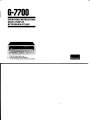
E-7700
OPERATING INSTRUCTIONS
MODE D'EMPLOI
BETRIEBSANLEITUNG
:x
:1
!
i
:t
$
&
!
i
:i
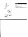
Read this manual before use.
Lire cette notice avant I'utilisation,
Vor der Verwendung diese Anleitung durchlesen.
-
We are grateful for your choice of this fine Sansui high fidelity product.
Before you operate it, we suggest that you read this booklet once
through carefully, familiarizing yourself with the important precautions, operational procedures and every one of the product's many
features. lt will help to ensure that you will avoid possible damage and
that the product's superb performance will be yours to enjoy for many
years to come.
4
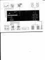
Precautions
Connections
I
Panel information
15
Operating procdures
Some useful hints
Specifications
26
38
44
WARNING: To prevent fire or shock hazard,
do not expose this appliance to rain or
moisture.
The Model No. and Serial No. of your unit aro shown on i$ back
pan€|.
. Oo not lose the Warranty
and Serial No.
Card that carries your unit's Model No.
t
Nous sommes reconnaissants pour votre choix de ce produit Sansui
d'une remarquable haute fid6lit6. Avant de commencer d vous en servir,
nous vous recommandons de lire cette notice compldtement et soigneusement, vous fam iliarisant ainsi avec les prdcautions importantes,
les manceuvres de fonctionnement et chacune des nombreuses caract6ristiques de I'appareil. Cela vous aidera d ne pas provoquer d'dventuels
dommages et a vous permettre de profiter pendant de longues ann6es
des superbes performances de votre appareil.
Pr6cautions
Connexions
lndicationssurlepanneau
Proc6d6sder6glage
Ouelquesconseilsutiles
Sp6cifications
...4
...8
.......15
......26
. . . . . . .38
........44
ATTENTION: Pour 6viter les dangers d'6lectrocution ou d'incendie, ne pas exposer cet
appareil d la pluie ou i I'humidit6.
Le num6lo du modCle et le num6ro de sdrie de lbppare3l sont
3ur son pannoau arriire.
Ne perdez
p6 b
carta de garantie
Sie vor der lnbetriebnahme des Gerdtes diese Anleitung sorgfdltig durch,
um sich mit den wichtigen VorsichtsmaBnahmen, den Bedienungsvorgdngen und den vielen hervorragenden Eigenschaften dieses Geretes
vollstdndig \,ertraut zu machen. Mogliche Beschddigungen krinnen
dadurch vermieden werden, so daB Sie das hervorragende Leistungsrermogen dieser Komponente fiir viele Jahre genieBen konnen.
VorsichtsrnaBnahmen
Anschltisse
Schalttafelinformation
Bedienungsrerfahren.
Einigen(itzlicheHinweise
TechnischeDaten
........4
....8
.........15
. . . . . . . .26
.......38
.....44
WARNUNG: Setzen Sie dieses Gerdt zur
Verh0tung von Feuer- und Stromschlaggefahr
weder Regen noch Feuchtigkeit aus.
imcrits
oi 6t.indiqu6e le num6ro
modAle et le num6ro dans la sdrie du type de l'apparail.
Wir mochten zu dieser Gelegenheit unseren Dank aussprechen, daB Sie
sich f0r diesen HiFi-Baustein von Sansui entschieden haben. Bitte lesen
du
Die Modell- und die Sedennummer lhros Goritc sind auf der
Geriteriickseite angegeben.
Verlieren Sie bitte nicht den Garantielchein, auf dem die Modcllund die Ssiennummer dicer Einheit angegeben sind.
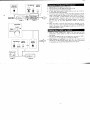
Precautions
lnstallation
r Never install the unit in dusty or humid
locations,
or in
close
proximity to heating appliances. Also, do not place it near a flower
basin or fish bowl, for accidental spillover may cause fire, electrical
*
r
shock and/or breakdown.
Keep the unit away from TV sets to avoid buzz noise.
When mounting the unit on a shelf, be sure that its supports are
solidly fixed.
Connection
r
*
r
When connecting or re-locating the unit, be sure to turn the power
off or disconnect the power cable.
Be sure not to confuse the right channel with the left, plus cables
with minus or inputs with outputs. Check each step carefully.
Use connection cords of dependable quality. Check that connections are secure and that connecting leads are not frayd or in
contact with other objects. Poor connection may cause hum noise
or breakdown-
Ventilation
*
r
*
f-/
\--L- 6JO
I
----1
r-\
r trtot _J
lnstall the unit where there is a good circulation of air.
Do not obstruct the ventilation opening of the cabinet.
Do not remove the cabinet cover or bottom board of the unit.
Pr6cautions
lnstallation
*
*
*
Ne placez jamais l'appareil dans un endroit poussi6reux ou humide,
ou d proximit6 imm6diate d'appareils de chauffage. De meme,dviter
la proximitd de bacs d fleurs ou d'aquariums. car une projection
accidentelle d'eau peut 6tre la cause de feu, de court-circuits violents
et/ou d'une panne de l'appareil.
Ne pas placer l'appareil prds d'un poste de tdldvision pour6viter les
gr6sillements.
Si vous installez l'appareil sur une 6tagdre, s'assurer que les supports
en soient bien fixds.
VorsichtsmaBnahmen
lnstallierung
*
*
Dieses GerAt niemals an Orten mit groBer Staubentwicklung oder
hoher Feu€htigkeit aufstellen; die Ndhe von Heizkorpern vermeiden.
Auch darauf achten, daB dieses Gerdt nicht in der Ndhe von Blumentopfen, Aquarien usw. aufgestellt wird, da es ansonsten durch
\erschiittetes Wasser zu elektrischen Sch ldgen, Feue rgef ahr u nd/oder
Beschddigung kommen konnte.
Dieses Ger6t moglichst entfernt von Fernsehgerdten aufstellen, um
induziertes Brummen zu vermeiden.
dieses Gerdt in Regalen eingebaut, darauf achten, daB deren
Festigkeit ausreicht, um das Gewicht abzustiitzen.
* Wird
Connexion
*
*
Ouand vous branchez l'appareil ou si vous l'installez dans un nouvel
endroit, assurez-vous de couper l'alimentation ou de d6connecter le
cable d'alimentation.
S'assurer de ne pas confondre le canal droit avec le canal gauche, les
cdbles de polaritd positive et ceux de polaritd ndgative et les entrdes
et les sorties. Controler chague 6tape soigneusement.
des fils de connexion de bonne qualit6. S'assurer que les
connexions soient parfaites et que les tetes d6nud6es des fils ne
soient pas cisaill6es ou en contact avec d'autres objets. De mauvaises
connexion peuvent 6tre la cause de grondements ou meme d'une
* Utiliser
AnschluB
* Zum
Anschlief3en bzw. wenn der Aufstellungsort dieses Gerates
gedndert wird, unbedingt den Netzschalter ausschalten und das
Netzkabel abziehen.
* Nicht den rechten Kanal mit dem linken, positive mit negativen
Kabeln bzw. Eingiinge mit Ausgdngen \erwechseln. Nach dem
Ansch lieBen unbedingt jede einzelne Komponente riberpruf en.
* Nur Verbindungskabel hoher Oualitdt benutzen. Auf richtigen
AnschluB achten und iiberprrifen, daB die Kabel nicht beschadigt
sind bzw. KurzschluB verursachen. Falscher AnschluB kann zu
Brumm ftihren oder des Ger6t beschddigen.
panne de l'appareil.
Ventilation
*
*
*
lnstaller l'appareil dans un endroit bien venti16.
Ne pas obstruer les ouvertures de ventilation du coffret.
N'enlevez pas le couvercle anti-poussidre ni le panneau de fond de
l'appareil.
Ventilation
*
*
*
Stellen Sie das Gerdt an einem Platz mit guter Luftzirkulation auf.
Verdecken Sie die Ventilationsof{nungen des Gerates nicht.
Niemals den Gehdusedeckel oder die Bodenabdeckung des Gerdtes
abnehmen.
5
l
Don't
NOTE: No AC outlet is provided on units
sold in some areas owing to local laws and
regu lations.
use
thinners on equipment
dry cloth to wipe the front panel or the cabinetry of this unit.
Never use thinners, alcohol or other solvents, or some of the words
indica:ted on the front panel may be erased or the dial plate may
become foggy. Also, when you use aerosol insecticide, be sure to avoid
Use soft,
spraying the unit.
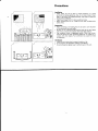
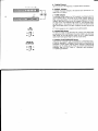
AC outlets
Of the two AC outlets provided on the rear panel, the one marked
REMAROUE: Aucune sortie AC (Courant
Alternatif) n'6quipe les moddles vendus dans
certaines 169ions en raison des 169lements
locaux.
ANMER KUNG : Aufgrund ortlicher Vorschriften und Gesetze sind in manche Gebiete gelieferte Gerdte nicht mit Wechselstromsteckdosen ausgestattet.
--AC
OUTT
swrTcN
IW
tD
TAX
SWITCHED, is controlled by the front-panel power s /itch. The other
one, marked UNSWITCHED, is not related to the power switch. The
former has a capacity of 100 watts and the latter 150 watts. Do not
connect any component whose power consumption exceeds these
capacities, as it is extremely dangerous.
The power consumption rating is usually listed in the specifications or
instructions of the component, or on the equipment itself; be sure to
check the rating.
o ln case you have connected a component to one of the unit's AC
outlets and then another component to the first component's
outlet, be sure to add the second component's rated power consumption to the consumption of the component connected to the
unit itself.
N'utilisez jamais du diluant synth6tique sur I'appareil
Pour nettoyer le panneau frontal ou le coffret de l'appareil il est recommand6 d'utiliser toujours un chiffon sec et doux. Ne jamais utiliser
du diluant synth6tique, de l'alcool ou d'autres diluants, car dans ce cas,
il est possible que quelques mots appos6s sur le panneau frontal
puissent se trouver effac6s ou que la paroi du cadran devienne opaque.
De m€me, quand vous utilisez un insecticide en adrosol d proximit6 de
l'appareil, prendre bien soin de ne jamais en r6pandre dessus.
Les sorties AC
Des deux sorties AC plac6es sur le panneau arridre, celle marqu6e
SWITCHED est command6e par le commutateur de puissance plac6 sur
le panneau frontal. L'autre, marqu6e UNSWITCHED n'est pas relide au
commutateur. La premidre a une capacitd de 100 Watts et la seconde de
150 Watts. Ne jamais connecter de composants dont la consommation
de puissance d6passe ces capacitds, car c'est extremement dangereux. Le
niveau de consommation de puissance est habituellement indiqud dans
les sp6cifications, dans la notice technique de ces composants ou sur les
appareils eux-m6mes. Bien contr6ler ces instructions.
. Dans le cas oD vous avez connect6 un composant A l'une des sorties
AC de l'appareil et puis un autre composant sur la sortie du premier
composant, s'assurer de bien ajouter la puissance consommde par le
deuxidme composant avec celle consommde par le composant
branch6 sur l'appareil lui-m€me.
Niemals Verdiinner zum Reinigen dieses Gerdtes verwenden
Die Frontplatte und das Gehiiuse dieses Gerates regelmiiBig mit einem
weichen und trockenen Putzlappen reinigen. Niemals Verdiinner,
Alkohol oder andere Losungsmittel verwenden, da ansonsten die
Beschriftung abgelost und die Skalenabdeckung getri.ibt werden
konnten. Auch darauf achten, daB lnsektenvertilgungsmittel nicht auf
dieses Ger6t gesprtiht werden.
Wechselstro m-Ausginge
Von den beiden an der Gereter[ickseite angebrachten WechselstromAusgangen ist der mit SWITCH ED gekennzeichnete Ausgang durch den
an der Frontseite angebrachten Netzschalter schaltbar; der zweite
Ausgang, gekennzeichnet mit UNSWITCHED, ist nicht mit dem
Netzschalter verbunden. Der erstgenannte Ausgang hat eine Nennleistung von'100 Watt, der zweite eine von 150Watt. Unbedingtdarauf
achten, daB an diese Ausgdnge angerhlossene Komponenten eine
Leistungsaufnahme haben, die geringer als die Nennleistung dieser
Ausg6nge ist, da ansonsten gefdhrliche Situationen hervorgerufen
werden konnten.
.Die Leistungsaufnahme der anzuschlieBenednen Komponenten ist
meistens an dem Bausteinen selbst angegeben oder kann der einsch169igen Anleitung entnommen werden.
o
Falls eine Stereo-Komponente an die Wechselstrom-Ausgangsbuchse
dieses Geriites angeschlossen ist und eine weitere Komponente mit
dem Wechselstrom-Ausgang der an dieses Gerdt angerhlossenen
Stereo-Komponente \€rbunden ist, dann darf die Summe der
Leistungsaufnahmen dieser beiden Komponenten nicht die Nennleistung des Wechselstrom-Ausganges dieses Gerdtes iibersteigen.
-
Gonnections
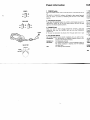
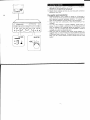
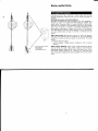
lndoor T-shaped FM antenna
Spread the antenna supplied out in the shape of a "T". Then while
listening to your favorite FM station change the direction and location
until the position where optimum, noise-free reception is found, and
secure the antenna.
B
Outdoor FM antenna
lnstallation of an outdoor FM antenna is recommended for very highquality FM reception. The T-shaped FM antenna supplied should be
used
only until you install an outdoor antenna.
1. The antenna should be installed as high and as far away as possible
from the street, railroad tracks and high-tension lines which
can
cause noise.
cable should be of the 75-ohm coaxial type, for it
of noise more effectively than the 300-ohm
twin lead type.
The lead-in cable should be as short and as far away from power
lines as possible. Simply cut off the extra length, if any. Be sure not
to bundle it into a coil.
FM antennas possess directionality. lnstall a highly directional type
antenna for improved noise-free reception. Refer to page 38.
2. The lead-in
suppresses intrusion
3.
4.
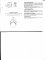
FM antenna connection
&-Pff
Use the FM 30o-ohm terminals when connecting the T-shaped FM
antenna supplied or a 300-ohm lead-in cable from an outdoor antenna'
Use the FM 75-ohm terminal when connecting a 75-ohm coaxial cable
from an outdoor antenna.
Gonnexions
Anschliisse
Antenne int6rieure FM en T
Zimmer-T-Antenne fiir U KW
Breiten Sie die mitgelieferten Antenne in Form eines "T" aus
Etirer l'antenne fournie en forme de "T". Ensuite tout en 6coutant une
6mission FM, changer la direction et l'inclinaison jusqu'd la position
optimum pour obtenir une r6ception exempte de bruit et enfin fixer
l'antenne.
und
Sndern Sie Richtung und Ort der Antenne, wiihrend Sie lhren beliebtesten UKw-Sender horen, bis Sie die Position fijr besten storungsfreien
Empfang gefunden haben, und befestigen Sie die Antenne in dieser
Position.
Antenne extdrieure FM
L'installation d'une antenne FM extdrieure est recommandde pour
obtenir une r6ception FM de trds bonne qualit6. L'antenne en forme de
T fournie avec l'appareil doit seulement €tre utilisde jusqu'A l'installation de l'antenne ext6rieure.
1. L'antenne doit 6tre install6e aussi haut que possible et le plus loin
qu'on peut de la rue, des lignes de chemin de fer et des lignes d
haute tension qui risquent de produire du bruit.
2.
Le cdble de raccordement
il supprime
3.
4.
les
doit €tre du type coaxial de 75 ohms, car
bruits intempenstifs plus s0rement que ceux du type
feeder de 300 ohms.
Le c6ble d'amen6e doit etre le plus court et le plus loin possible des
lignes d'alimentation. ll suffit de supprimer la longueur en excds,
quand il y a lieu. S'assurer de ne pas le mettre en boule.
Les antennes FM possddent un sens de direction. lnstaller une
antenne directionnelle afin d'obtenir une r€ception d faible bruit
amdlior6e. Se rdfdrer d la page 38.
Connexion de l'antenne FM
Utiliser les bornes FM de 300 ohms quand vous connectez l'antenne
feeder en forme de T fournie avec l'appareil, ou un cSble de 300ohms
provenant d'une antenne ext6rieure.
Utiliser les bornes FM de 75 ohms quand vous connectez un cdble 75
ohms provenant d'une antenne exterieure.
UKW-AuBenantenne
UKW-Empfang sehr hoher Oualitiit wird die lnstallierung einer
UKW-Auf3enantenne empfohlen. Die mitgelieferte T-formige UKWAntenne ist nur als Zwischenlosung gedacht, bis eine AuBenantenne
installiert ist.
1. Die Antenna sollte so hoch wie moglich und so weit wie moglich
von StraBen, Eisenbahnlinien und Hochspannungen entfernt installiert werden, da diese Storungen verursachen konnen.
Fiir
2. Die Amennenzuleitung sollte aus einem
3.
4.
75Ohm-Koaxialkabel
bestehen, da ein solches Kabel bessere Abschirmung als ein 300O hm-Kabel mit Paarverseilung gewdhrleistet.
Das Zuleitungskabel sollte so kurz wie moglich sein und von
Stromleitungen ferngehalten werden. Schneiden Sie eventuelle
UberlSngen einfach ab. Wickeln Sie sie nicht zu einer Rolle (Spule)
zusammen.
UKW-Antennen haben Richtwirkung. lnstallieren Sie eine Richtantenne frjr verbesserten Empfang
Sie sich bitte auf die Seite 38.
mit weniger Storungen.
Beziehen
AnschluB der U KW-Antenne
Die mit FM 300 Ohm bezeichneten Klemmen fiir den AnschluB der
mitgelieferten T-formigen UKW-Antenne bzw. der 300Ohm-Zuleitung
von einer Aul3enantenne verwenden.
Die 7SOhm-Klemmen benutzen, wenn eine 75ohm-Antennenzuleitung von einer UKW-Auf3enantenne verwendet wird.
-
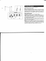
While actually listening to an AM station, pull the rear-panel bar
antenna and align in the direction where you get the best reception. To
avoid noise, do not run the power cable or speaker cables in the vicinity
10
of the antenna.
Further advice for better AM reception.
'l . Move the antenna away f rom the wall.
2. Place the unit near the window.
3. Re-align the unit itself.
4. Connect a PVC cord to the AM ANTENNA terminal and extend it
outdoors-
Lroo"J
Tout en 6coutant une station. AM, tirer sur l'antenne d barreau du
panneau arridre et l'aligner dans le sens or] l'on obtient la meilleure
r6ception. Pour dviter le bruit, ne pas faire courir le fil d'alimentation
ou bien les cdbles de haut-parleurs dans le voisinage de l'antenne.
Voici encore d'autres conseils pour une meilleure r6ception AM.
1. Eloigner l'antenne du mur.
2. Placer l'appareil prds de la fenetre.
3. Rdaligner l'appareil lui-m€me.
4. Connecter un cordon PCV A la borne AM ANTENNA et l'dtirer
l'extdrieu r.
Ziehen Sie die Stabantenne an der Rtickseite des Gerdtes nach oben und
richten Sie sie fi.ir besten Empfang aus, wdhrend Sie tatsachlich einen
MW-Sender empfangen. Leiten Sie zur Vermeidung von Storungen
weder Netzkabel noch Lautsprecherkabel in der Ndhe der Antenne
vorbei-
Nachfolgend finden Sie einige weitere Hinweise
fiir
besseren MW-
Empfang.
A
i. Bewegen Sie die Antenne von der Wand weg.
2. Stellen Sie das Gerdt in der Ndhe eines Fensters auf
3. Richten Sie das Gerat selbst aus.
4. Schlief3en Sie ein PVC-Kabel an die Klemme AM ANTENNA
.
Verlegen Sie es ins Freie.
an und
11
\-
\i
-F*:-i'f
infl
e/+tl ih,.,r,r'
M
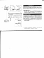
Speaker systems
To SPEAKER SYSTEM-A or B terminals, connect speaker cords taking
care not to confuse the right channel with the left, the plus polarity
with the minus.
. Be sure that exposed leads are firmly secured to the terminals.
/\\' rL
Turntable
l@ll@)
r-
I
SPEAKEF SYSTEM.A
*u-
Connect your turntable to the PHONO terminals. lf your turntable is
equipped with a grounding cable, connect it to the unit's GND terminal. But disconnect it if you notice increased hum.
o lf your turntable has a crystal or ceramic cartridge, connect it to
TAPE/AUX inputs, not PHONO inputs.
r The shorting pin plugs should be inserted into unused PHONO input
terminals, but not into any other terminals; otherwise, signals will
be interrupted and sound may not come from speakers.
Tape deck
You can connect up to two tape decks to the unit. Connect the unit's
TAPE REC terminals to the line input terminals of your tape deck, and
the unit's TAPE PLAY terminals to the output terminals of the deck.
Dolby NR adaptor
The Dolby NR (decoder) adaptor is used when you want to play back a
Dolbyized tape on a non-Dolby tape deck,orwhen you receive Dolbyized FM broadcasts, and enjoy hiss-free reproduction. Connect your
Dolby N R adaptor to the TAPE-2 terminals on the unit.
t
0 00 00 ,A\00,4\
00 000
oOooUo(JOooo
Dolby NR adaptor
Adaptateur Dolby NR
0olhy-N R-Adapter
Dolby is a trademark of Dolby Laboratories, lnc.
13
Lautsprecherboxen
Enceintes
Pour les bornes SPEAKER SYSTEM-A ou B, connecter les cdbles des
enceintes en prenant bien soin de ne pas confondre le canal droit et
gauche et la polarit6 positive avec la n6gative.
. Eien s'assurer que les parties exposdes des conducteurs sont bien
fix6es dans les bornes.
-
An die mit SPEAKER SYSTEM-A oder B bezeichneten Klemmen sind
die
Lautsprecherkabel anzuschlief3en; dabei jedoch darauf achten, daB
der rechte nicht mit dem linken Kanal und der positive Leiter nicht mit
dem negativen verwechselt wird.
. Darauf
achten, daB die blanken Leiter richtig an den Klemmen
gesichert sind.
Tournedisque
Raccorder votre tournedisque aux bornes PHONO. Ouand votre
tournedisque est muni d'un cdble de Mise ir la terre, le raccorder d la
borne GND de l'appareil. Mais deconnectez-le si vous remarquez une
augmentation anormale du ronf lement.
. Si votre tournedisque possdde une cellule de cristal ou cdramique,
la connecter aux entr6es TAPE/AUX au lieu des entr6es PHONO.
r Les fiches de mise en courtcircuit devront 6tre introduites seulement dans les bornes d'entr6e PHONO inutilis6es e l'exception de
toute autre borne; autrement, les signaux seront interrompus et il
est possible qu'aucun son ne provienne des enceintes.
Magn6tophone
Vous pouvez raccorder jusqu'd deux magndtophones sur l'appareil.
Raccorder les bornes TAPE REC de l'appareil aux bornes d'entrde de
votre magn6tophone et les bornes TAPE PLAY de l'appareil aux
14
Plattenspieler
lhren Plattenspieler an die Klemmen PHONO
Plattenspieler mit einem
anschlief3en; Wenn lhr
Erdungskabel ausgestattet ist, dieses an die
Klemme GND des Gerates anschlieBen; falls jedoch dadurch der Brumm
verstarkt wird, das Erdungskabel wieder abklemmen.
. Wenn lhr Plattenspieler einen Kristall- oder Keramiktonabnehmer
hat, so schlieBen Sie ihn bitte nicht an die PHONO-Eingange
sondern an die TAPE/AUX-Eing6nge an.
o Wenn die PHONO Klemmen nicht belegt sind. unbedingt die Blindstecker anstecken; diese jedoch an keinen anderen Klemmen
einstecken, da ansonsten Beschddigungen auftreten bzw. die Lautsprecher unterbrochen werden konnten.
Tonbandgeriite
bornes de sortie de votre magndtophone.
Sie konnen nach Wunsch bis zu zwei Tonbandgerate anschlieBen. Die
Klemmen TAPE REC dieses Ger6tes mit den Eingangs- und die
Klemmen TAPE PLAY mit den Ausgangsklemmen des Tonbandgeretes
Adaptateur Dolby NR
verbinden.
L'adaptateur (ddcodeur) Dolby NR doit €tre utilisd guand vous ddsirez
procdder d la reproduction d'une bande Dolby-s6e avec un magn6tophone ne poss6dant pas de systdme Dolby, ou quand vous recevez des
6missions FM Dolby-s6es pour pouvoir obtenir une r6ception sans
parasites. Raccordez votre adaptateur Dolby NFI aux bornes TAPE-2
Der Dolby-NR-Adapter (Dekoder) wird verwendet, wenn dolbysierte
Bandaufnahmen auJ einem Tonbandgeret ohne Dolby-Bauschunter-
de l'appareil.
Dolby-NR-Adapter
driickung abgespielt oder wenn dolbysierte UKW-Rundfunkprogramme
empfangen werden. Den Dolby-NR-Adapter an die TAPE-2 Klemmen
dieses Geretes anschl ieBen.
t Dolby est la marque ddposde
I
nc.
des dtablissements
Dolby Laboratories,
t Dolby ist ein Markenname der Dolby Laboratories,
lnc.
This page folds out for use as reference
while reading th€ rest of the booklet.
. C6tte pago se plie i l'ext6rieur
r6te de la notice.
15
pour
l'utiliser comme r6f6rence tout en lisant le
. Bitte
klappen Sie diese Seite heraus, wenn
Sie den Rest dieser Anleitung durchlcen.
-
lndic
Panel information
POWER
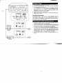
1 POWER Switch
Push the POWER switch once to
off.
0t{
16
turn the unit on, once more to turn
it
1
lntel
Appuyer
fonction
The SAFELY OPERATE lndicator will begin to glow several seconds Le t6moi
after the switch is turned on, indicating that the unit is now ready le comm
OFF
SPEAKERS
::,f,; f,::,
operate.
I'appareil
2 SPEAKERS Switches
2
They select the speaker systems (A and B) to which signals are sent for
reproduction. When set to ON, the switch permits the unit to send
signals to the selected speaker systems.
3
PHONES Jack
When you want
to
listen through headphones privately, insert
Com
Ces comt
B) auxqr
est sur la
slgnaux €
the 3
Ptise
hedphone plug into the PHONES jack and turn the SPEAKERS Ouand
off.
switches
Be sure
o
to disconnect the
phones from the jack when not
in
SELECTOR Switch
Set to the program source (record, broadcast, etc.) you wish to
usd.
4
I
6couteur
PHONES
prenc
.
prise
hear.
TAPE/AUX: For
4
PHONO-1,2:
FM AUTO:
TAPE/A
SETECTO R
AM:
reproduction of whatever program source is connected to the TAPE/AUX inputs.
For playing disc records.
For receiving FM stereo or mono broadcasts. When an
FM stereo broadcast is received, the FM STEREO
indicator lights.
For receiving AM broadcasts.
Con
Rfuler s
d6sire dc
PHONO.
FM AUI
FM AUTO
AM:
lndications sur le panneau
-
Scha lttafel i nformation
1 lnterrupteur d'alimentation (POWER)
Appuyer une fois sur le bouton POWER pour mettre l'appareil
en
1 Netzschalter (POWER )
Driicken Sie den POWER Schalter zum Einschalten des
Gerdtes,
fonction, et une deuxidme fois pour l'arreter.
Le tdmoin SAFELY OPEBATE s'allumera quelques secondes aprds que
le commutateur d'alimentation ait 6td manoeuvrd, indiquant ainsi que
l'appareil est pret d fonctionner.
dri.icken Sie ihn erneut zum Ausschalten.
2
Ces
K E RS)
commutateurs seryent d sdlectionner les enceintes acoustiques (A et
B) auxquelles sont envoy6es les signaux pour la reproduction. Ouand il
est sur la position ON, le commutateur permet d l'appareil d'envoyer les
2 Lautsprecherschalter (SPEAKERS)
An dieses Gerdt konnen bis zu zwei Boxenpaare angeschlossen werden,
die iiber diese beiden Schalter in Betrieb gesetzt werden konnen.
Wenn auf Position ON gestellt, dann ermoglicht dieser Schalter die
signaux aux enceintes acoustiques choisies.
Absteuerung des ausgewiihlten Boxenpaares.
3
Prise de casque-6couteurs (PHONES)
Ouand vous d6sirez dcouter de la musique d l'aide d'un casque6couteurs, introduire la fiche du casque4couteurs dans la prise
3
PHONES et couper les commutateurs SPEAKERS.
abscha lten.
Gommutateu rs d'enceintes acoustiques (SPEA
Die SAFELY OPERATE Anzeige leuchtet einige Sekunden nach dem
Einschalten des Netzschalters auf und zeigt damit die Betriebsbereitschaft des Gerates an.
Kopfhiirerbuchse (PHONES)
Fiir ungestortes Hovergen0gen ein
Paar HiFi-Stereo-Kopfhorer an die
PHONES Buchse anschliel3en und die beiden SPEAKERS Schalter
o
Prendre bien soin de d6brancher la fiche du casque-6couteurs de la
prise quand on ne l'utilise pas.
.
Werden die Kopfhorer nicht verwendet, diese unbegingt vom Geret
abtrennen.
4
Commuateur de s6lecteur (SELECTOR)
4
Wahlschalter (SELECTOR)
Rdgler sur la source de programme (disque,6mission, etc.) que l'on
d6sire 6couteur.
TAPE/AUX:
PHONO-I,2:
FM AUTO:
AM:
Pour reproduire n'importe quelle source de
pro-
gramme connectde aux entrdes TAPE/AUX.
Pour passer des disques.
Pour recevoir des dmissions mono ou FM stdr6o.
Ouand une dmision FM stdrdo est reque, le t6moin
FM STEREO s'allume.
Pour recevoir des 6missions AM.
Stellen Sie die Programmquelle (Plattenspieler, Radio usw.) ein, die Sie
horen wollen.
TAPE/AUX: Wiedergabe der an die Klemmen TAPE/AUX ange-
PHONO-I,2:
FMAUTO:
AM:
schlossenen Programmquelle.
Fiir das Abspielen von Schallplatten.
FUr den Empfang von UKW Stereo- oder MonoSendungen. Wenn eine UKW-Stereo-Sendung empfangen
wird, leuchtet die FM STEREO Anzeige auf .
Fiir den Empfang von Mittelwellensendungen.
17
5
TUNING Control
Use
it to tune in on the frequency of
a desired
6
SIGNAL lndicator
7
TUNE lndicator
8
FM MUTING Switch
9
DOLBY FM DE-EMPHASIS Switch
AM or FM station.
indicates the signal strength at the antenna input terminals of a received AM or FM station.
It
FM
MUTIiIG
oxn
,rrlLJTll
D,
-
DOTBY FM
DE.EMPHASIS
*;f,=
The optimal tuning position for FM broadcasts is achieved when the
round indicator light in the center of the TUNE indicator lights up.
When tuning slips slightly f rom the optimal tuning position, the round
indicator light goes off and one of the triangular indicators at the left
and right of the round indicator light comes on. The triangular indicator lights point in the direction the tuning control should be moved.
When tuning slips totally from signal, triangular indicator lights also go
off.
o TUNE lndicator is not in operation during AM reception.
The built-in muting circuit eliminates the irritating noise heard while
you are tuning from one FM station to another. Since it also eliminates
weak signals, set the FM MUTING switch to OFF to receive faraway
stations with faint signals. Keep it at ON at all other times.
Dolbyized FM broadcasts must be processed by a deemphasis value a curve of attenuation - different from the one for conventional FM
broadcasts to obtain proper response. When receiving a Dolbyized FM
broadcast, set this switch to ON. When you receive conventional FM
broadcasts, keep it at OFF. Refer to "Listening to radio broadcasts"
in "Operating procedures".
-
5
Commande de syntonisation (TUNING)
L'utiliser pour s'accorder sur la frdquence de la station FM ou AM
d6sir6e.
6 T6moin de puissance
ll
du signal (SIGNAL)
indique le puissance du signal aux bornes d'entrde de l'antenne d'une
station FM ou AM.
7 T6moin d'accord
(TUNE)
La position d'accord pour les 6missions FM est optimale lorsque la
lampe ronde du t6moin TUNE s'allume. Lorsque l'accord glisse l6gdrement de la position optimale, la lampe ronde s'6teint et l'une des
lampes triangulaires d gauche ou d droite de la lampe ronde s'allume.
Les lampes triangulaires indiquent le sens dans lequel la commande
d'accord doit 6tre ddplac6e. Lorsque l'accord ne se fait plus sur le
signal de la station, les lampes triangulaires du t6moin s'dteignent
dgalement.
. Le t6moin TUNE ne fonctionne pas lors d'une reception AM.
8
lnterrupteurde sourdine FM (FM MUTINGI
circuit incorpo16 de sourdine 6limine les parasites ddsagr6able; que
l'on peut entendre quand on change de station FM. Comme il supprime
aussi les signaux de faible puissance, mettre l'interrupteur FM MUTING
sur la position OFF pour €tre capable de recevoir les stations dmettrices
lointaines aux signaux faibles. Le garder sur la position ON dans tous les
Le
autres cas.
9
lnterrupteur d'att6nuation du dispositif Dolby FM
(DOLBY FM DE.EMPHASIS)
FM Dolby doivent subir un processus d'att6nuation - une
courbe d'att6nuation - qui est diffdrent de celui destin6 aux dmissions
FM cohventionnelles, pour obtenir la rdponse correcte. Ouand on regoit
une dmission FM Dolby-sde, mettre cet interrupteur sur la position ON.
Ouand on reqoit des 6missions FM conventionnelles, laisser cet interrupteur sur la position OFF. Rdf6rer au paragraphe "Ecoute de la radio"
dans le chapitre "Proced6s de 169lage."
Les dmissions
5
Senderabstimmknopf (TUNINGI
Diesen Knopf zum Abstimmen der Frequenz des gewl.inrhten MW- oder
UKW-senders verwenden.
6
Signalstdrkeanzeige (SIGNAL)
Dieses lnstrument zeigt die Signalstiirke eines empfangenen MW- oder
UKW-Senders an den Antenneneingangsklemmen an.
7
Abstimmanzeige (TUNE)
Die Stellung fiir optimale Abstimmung von UKW-Sendungen ist
19
bei
Aufleuchten der runden Anzeigeleuchte in der Mitte der TUNE Anzeige
erreicht. Wenn sich die Abstimmung Ieicht von der optimalen Abstimmstellung verschiebt, erlischt die runde Anzeigeleuchte, und eine der
Dreieckanzeigen links und rechts von der runden Anzeigeleuchte
leuchtet auf . Die Dreieckanzeigeleuchten weisen in die Richtung, in
welcher der Abstimmknopf gedreht werden sollte. Weicht die Abstimmung ganz vom Sender ab, erloschen die Dreieckanzeigeleuchten ebenfa I ls.
. Bei Mittelwellenempfang ist die TUNE Anzeige nicht in Betrieb.
8
UKW-Stummabstimmungsschalter
(FM MUTING)
Diesen Schalter auf Position ON stellen, um bel der Sendersuche im
U KW-Bereich lSstiqes Zw ischenstationsrau schen zu vermeiden. Fa lls es
sich bei dem gewiinschten Sender um eine sehr schwach einfallende
Station halten, den FM MUTING Schalter auf Position OFF stellen, da
schwache und stark verrauschte Sender ansonsten ebenfalls unterdnickt
werden. Fiir alle anderen Falle diesen Schalter auf Position ON stellen.
9
Deemphasisschalter fiir dolbysierte UKW-Programme
(DOLBY FM DE.EMPHASIS)
Dolbysierte UKW-Programme mtissen mit einem unterschiedlichen
Deemphasiswert als herkommliche U KW-Programme verarbeitet werden.
FLir den Empfang von dolbysierten UKW-Sendungen diesen Schalter
auf Position ON stellen. Werden herkommliche (nicht dolbysierte)
UKW-Programme empfangen, diesen Schalter immer auf Position OFF
stellen. Beziehen Sie sich bitte auf ddm Abschnitt "Horen von Badiosendungen" im Kapitel "Bed ienungsverf ahren".
MONITOR
2
1
TAPE
s0uRcE
SOURCE
TAPE
TAPE
10
MO]IITOR
-
rate record and PlaYback heads.
When dubbing from the TAPE-1 deck to the TAPE-2 deck, set the
TAPE MON ITOR-1 switch to the TAPE position.
o When you finish playing back, monitoring or dubbing, push the
switch once more to release it.
coPYl>2
11
PEAK P0WER
t20 25 5.0 t.0
as you
record, push the TAPE MONITOR-1 or -2 switch, whichever is applicable for the tape deck you wish to use. Monitoring of your recording
while you record is only posible with 3-head tape decks having sepa-
20
rFFr
TAPE MONITOR Switches
To play back a recorded tape or to monitor your recording
SOURGE
0.25 0.05
tEVEI WATTS/8o
0.01
0.01 0.05 0.25
VOTUME
1.0 5.0 25
SOURCE MONITOR switch
When this switch is set to ON, you will be able to hear the sound of the
program which you have selected with the SELECTOR switch regardless of the position of the TAPE MONITOR switch.
120
12PEAK POWER LEVEL indicator
This indicator shows the volume. When speaker systems with ah imped'
ance of 8 ohms are used, the lighred length of this indicator shows the
volume in accordance with the power delivered.
13VOLUME Control
It adjusts the output level (volume) of your
the right it is turnd, the greater the volume.
audio system. The more to
j
10 Interrupteurs de contrOle de bande
(TAPE MONITOR)
Pour reproduire une bande magndtique ou pour controler votre enregistrement au fur et d mesure que vous enregistrez, enfoncez l'interrupteur TAPE MONITOR-I ou -2 suivant lequel est utilisable pour le
magndtophone que vous voulez utilisez, Le controle de votre enregistrement au fur et d mesure gue vous enregistrez n'est possible que si vous
poss6dez un magn6tophone A trois tetes ind6pendantes dont celle pour
la reproduction et celle pour l'enregistrement.
Ouand on procdde d un copiage de bande de la platine TAPE-I vers
la platine f APE-2, mettre l'interrupteur TAPE MONITOR-1 sur la
position TAPE.
. Ouand vous avez fini la reproduction, le contr6le de bande ou le
copiage de bande, poussez encore une fois sur l'interrupteur qui
reviendra dans la position relach6e.
11 lnterrupteur de contr6le de source (SOURCE MONITORI
Ouand cet interrupteur se trouve sur ON, on peut €couter le son du
programme choisi par le commutateur SELECTOR, ind6pendamment
position de l'interrupteur TAPE MONITOR.
10 Bandmithrirschalter (TAPE MON ITOR I
Ftir die Wiedergabe eines bespielten Tonbandes oder zum Mithoren der
Aufnahme, den TAPE MONITOR-1 oder -2 Schalter drticken, je nachdem an welche Klemmen das Tonbandgerdt angeschlossen ist. Mithoren
der Aufnahme (d.h. Hinterbandkontrolle) ist nur moglich, wenn das
Tonbandgeriit mit drei Tonkopfen (getrennter Tonkopf fiir Aufnahme
und Wiedergabe) bestiickt ist.
Wenn eine Tonbandaufnahme von TAPE-I auf TAPE-2 iiberpielt
werden soll, denTAPE MONITOR-1 Schalter auf Position TAPE stellen.
.
Nach Beendigung derWiedergabe, des Bandmithorens bzw. des Uberspielen, den Schalter durch nochmaliges Dfi.icken wieder freigeben.
11
Mithcirschalter (SOURCE MONITOR)
Wenn dieser Schalter auf ON gestellt wird, konnen Sie den Ton des
Programms abhoren, dasSie mit Hilfe desSEIECTOR Schalters gewehlt
haben, ohne Riicksicht auf die Stellung des TAPE MONITOR Schalters.
1
2
Spitzenpegel-Leistungsanzeige (PEAK POWER LEVEL)
de la
Diese Anzeige zeigt die Lautsterke an. Wenn Lautsprecherboxen mit
l2T6moin de niveau de puissance de cr€te
(PEAK POWER LEVEL)
ll sert d indiquer le volume. A l'emploi de enceintes acoustiquesd'une
dieser Anzeige
Leistung an.
impddance de 8 ohms, la longueur 6clair6e de ce tdmoin indique
tensit6 du volume en fonction de la puissance d6livr6e.
l3Commande de volume (VOLUME)
l'in-
Cette commande sert a rdgler le niveau de sortie (volume sonore) de
votre ensemble stdr6o. Plus il est tournd vers la droite, plus le niveau du
son est 6lev6.
8
Ohm lmp€danz
angeschlossen sind, zeigt
die erleuchtete
Lenge
die Lautstarke in Ubereinstimmung mit der geliefenen
13 Lautstdrkeregler (VOLUME
Mit diesem Regler wird der
)
Ausgangspegel
lhrer HiFi-Anlage geregelt.
Den Regler nach rechts drehen, um die Lautstarke zu erhohen.
-
21
14AUDlO MUTING Switci
AUDIO
MUTIIIIG
,:,'"f,=
With this switch, you can reduce the volume by 20 dB instantly. lt is
most convenient when you reduce the volume temporarily on such
occasions as when you answer a phone call or place a stylus on the
record surface. Adjustment of the volume of very low sounds is easily
carried out by adjusting the VOLUME control after the AUDIO
MUTING switch has been set to the '-20 dB' position.
15MODE Switch
to listen to mono records or tapes reproduced
Push
MODE
: f,::T'
BAIAIIGE
02
-
using a monophonic
cartridge or tape deck. The monophonic equipment may be connected
to either the rearpanel right or left input. The sounds will be mixed
and reproduced from both speakers.
o The MODE switch is used to change an FM stereo broadcast into a
mono one. Also, use it when you wish to record an FM stereo
broadcast in mono. By depressing this switch, the noise heard in
an FM stereo broadcast is greatly reduced when receiving the FM
signal in mono.
l6BALANCE Control
8
The volume of the left and right speakers can be adjusted by the
BALANCE control. As the control is turned counterclockwise f rom the
center position, the sound from the left speaker becomes louder than
that from the right speaker, and vice versa. Adjust so that the sounds
from the left and right speakers are heard with equal volume at your
listening position.
Mtc MlxlilG
tEVEt
.E
17 MIG Jack
18MlC MIXING LEVEL Control
lnsert a microphone plug into the Jront-panel MIC jack and adjust its
Mlc MlxlNG LEVEL control. You can mix microphone
sounds with other program sources. (Refer to page 36).
. When no microphone is used, be sure to turn, its control fully
counterclockwise to the "0" position.
level with the
I
I
I
i
I
14 lnterrupteur d'attdnuation audio (AUDIO MUTI NG )
Avec cet interrupteur, on peut r6duire le volume de 20 dB instantandment. Cela s'avdre trds pratique pour r6duire le volume momentan6ment lorsgue le t6l6phone sonne ou pour placer la pointe de lecture sur
le disque. Le r6glage du volume des sons trds faibles s'effectue aisdment
MUTING a la position '-2O dB.'
14 Schalter fOr Geriiuschsperre (AUDIO MUTING)
diesem Schalter konnen Sie die Lautstarke sofort um 20 dB verringern. Dies ist bequem frir zeitweilige Verringerung der LautstArke
beim Telefonieren oder beim Aufsetzen der Nadel auJ eine Schallplatte.
Lautstarkeregelung fiir sehr leise Tone gerhieht einfach durch Einstellung des VOLUME Reglers mit dem AUDIO MUTING Schalter in der
Stellung '-2O dB.'
15lnterrupteur de mode (MODE)
1
par la commande VOLUME aprds avoir rdgld l'interrupteur AUDIO
Sert A dcouter les disques mono ou pour la reproduction des bandes
en utilisant un magndtophone ou une cartouche monophonique.
L'6quipement monophonique peut 6tre connectd d la prise d'entrde
gauche ou droite du panneau arridre. Les sons se trouvent alors mdlangds et reproduits par les deux haut-parleurs.
. L'interrupteur MODE sert a changer une dmission FM stdr6o en
mono. De mdme, appuyer dessus lorsqu'on ddsire enregistrer une
dmission FM stdr6o en mono. En appuyant sur cet interrupteur, le
bruit entendu dans une6mission FM stdrdo en recevant un signal FM
mono est grandement r€duit.
16
Commande d'6quilibrage (BALANCE
)
Le volume des enceintes acoustiques gauche et droite peut €tre 16916
par la commande BALANCE. Si la commande est tourn6 dans le sens
contraire des aiguilles d'une montre d partir de sa position mddiane, le
son de l'enceinte acoustique gauche sera accentud par rapport d celui de
l'enceinte acoustique droite, et vice-versa. R6gler de fagon que le son
provenant des enceintes acoustiques gauche et droite soit entendu
avec la mdme intensitd depuis la position d'6coute.
jack de micro (MlC)
lSCommande de niyeau micro (MlC MIXING LEVEL)
17 Prises
lntrodJire une prise de microphone dans la prise jack MIC du panneau
i l'aide de la commande MIC MIXING
frontal et ajuster le niveau
LEVEL. Vous pouvez aussi mdlanger des sons provenant du micro avec
des sons d ?utres sources de programmes. (Se r6f6rer A la page 36)
.
.
Ouand on n'utilise pas de microphone, prendre bien soin de tourner
sa commande compldtement dans le sens contraire des aiguilles
d'une montre sur la position "0".
Mit
5 Betriebsartenschalter (MODE I
Frir die Wiedergabe von monauralen Schallplatten oder Tonbdndgern
tiber Mono-Plattenspieler oder -Tonbandgerat. Die Mono-Ausriistung
kann entweder an den linken oder an den rechten Eingang an der
Geraterilckseite angeschlossen werden. Die Tone werden gemischt und
von beiden Lautsprechern wiedergegeben.
r Der MODE
Schalter dient zum Umschalten einer UKwstereo-
Sendung in eine Mono-Sendung. Verwenden Sie ihn auch, wenn Sie
eine UKWStereo-Sendung monaural aufnehmen wollen. Durch
Driicken dieses Schalters werden die Storungen bei Empfang einer
U KWStereo-Sendung in Mono-Betrieb start verringert.
16 Balanceregler (BALANCE)
Mit dem BALANCE Regler kann die Lautstarke der linken und rechten
Lautsprecher eingestellt werden. Durch Drehen des Reglers aus der
Mittelstellung nach links wird der linke Lautsprecher lauter als der
rechte und umgekehrt. Stellen Sie so ein, daB Sie an dem Platz, an dem
Sie hclren wollen, beide Lautsprecher gleich laut horen.
17 Mikrofonbuchse (MlC)
18 Mikrofonpegelreglel (MlC MIXING LEVEL)
Mikrofonstecker an die MIC-Buchse an der Geretefrontseite anschlieBen
und den Mikrofonpegel mittels MIC MIXING LEVEL Regler aus-
starern. Mikrofonbeimischung zu anderen Programmquellen
ist
ebenfalls moglich (siehe Seite 36).
. Wird kein Mikrofon verwendet, unbedingt den Mikrofonpegelregler
bis zu Position "0" gegen den Uhrzeigersinn drehen.
23
t0u
19 LOUDNESS Switch
this switch when listening at a low volume level accents the
DttlEss
Pushing
: f::
lows and highs properly to render the reproduced sound more realistic.
This compensates for the fact that the human ear becomes insensitive
to the lows and highs as the sound volume is reduced.
20TONE Switch
To adjust tone with the tone controls, first set the ToNE switch to the
ON position. To obtain a flat response, set it to the DEFEAT position.
Then the tone control circuits are switched out of the signal path
irrespective of the positions of the tone controls.
ToNE
24
trtt;:
f :
21 BASS Tone Control
Sounds of a bass and other low-frequency sounds can be emphasized or
deemphasized by ad,justing BASS tone control.
TBEBLE
BASS
-20
+2
-20 -\+4
\
\+6
\{l
+6
I
\JA
Sounds of cymbals and other high-frequency sounds can be emphasized
or deemphasized by adjusting the TBEBLE tone control.
23 SUBSONIC FILTER Switch
Superflow-frequency noise, caused by warped or offcentered records,
forces the moving structure of a woofer to work excessively; such
abnormal excursion generates d istortion.
This filter cuts such superlow-frequency noise below 16 Hz and im.
proves bass response.
FITTEBS
SUBSOTUIC HIGH
"';f,:
22TREBLE Tone Control
+2
24 HIGH FILTER Switch
to the ON position when scratch noise of records or
hiss of recorded tapes is irritating.
o Do not use this filter unless the high-frequency noise is excessirrely
Set this switch
f
::'
annoying.
En enfongant cet interrupteur lors de l'6coute d faible niveau sonore,
cela permet d'accentuer les graves et aigus de fagon convenable pour
donner un effet plus r6aliste des sons reproduits. Cela compense le fait
que l'oreille humaine devient insensible aux graves et aux aigus d mezure
que le volume sonore€st rftuit.
19 Geh<irrichtige Lautstdrkekorrektur (LOUDNESS)
Durch Druck auf diesen Schalter beim Horen mit geringer Lautsterke
werden die Tiefen und Hohen richtig akzentuiert, um die Tonwiedergabe realistischer zu machen. Hierdurch wird fi.lr die Tatsache kompensiert, daB das menschliche Ohr bei verringerter Lautstiirke
unempf indlich fiir tiefe und hohe Tone wird.
20 lnterrupteur de tonalit6 (TONE)
Pour ajuster la tonalitd avec les commandes de reglage de tonalit6, il
20 Klangschalter (TONE)
Stellen Sie zur Klangregelung mit Klangreglern zuerst den Schalter
l9lnterrupteur de contour sonore (LOUDNESS)
faut d'abord regler l'interrupteur TONE sur la position ON. Pour
obtenir une rdponse plate, le r6gler sur la position DEFEAT. Ensuite les
circuits de reglage de tonalitd sont s6pards du circuit quelles que soient
les positions de tonalitd et des commandes de reglage de tonalit6.
21 Commande de tonalit6 grave (BASS)
Les sons graves et les autres sons de basses fr6quences peuvent etre
exag6r6s ou diminu6s en 169lant la commande de tonalite BASS.
22 Commande de tonalit6 aigui (TREBLE)
Les sons de cymbales et les autres sons de hautes frdquences peuvent
6tre exag6r6s du diminu6s en r6glant la commande de tonalit6 TB EBLE.
23
lnterrupteur de filtre subsonique (SUBSONIC FILTER)
Les bruits parasites de trds basses frdquences, causds par des disques
rayds ou d6centr6s, entrainent une contrainte excessive des dldments
mobiles d'un woofer; cette contrainte provoque une distorsion sonore.
Ce filtre supprime de telles trds basses fr6quences audessous de l6 Hz
et amdliore la rdponse des graves.
24lnterrupteur de filtre haut (HIGH FILTER)
Mettre cet interrupteur sur la position ON quand les bruits provoquds
par leS rayures d'un disque ou les sifflements de bandes enregistrdes
deviennent d6sagrdables.
. Ne pas utiliser ce filtre sauf dans les cas o0 les bruits parasites de
hautes fr6quences sont excessivement irritants.
TONE in die Stellung ON. Stellen Sie ihn fiir flachen Frequenzgang in
die Stellung DEFEAT. Die Klangregelstromkreise werden dann unabhdngig von der Stellung der Klangregler abgeschaltet.
21 BaBklangregler {BASS}
Die B6sse, d.h. der untere Frequenzbereich, konnen mit Hilfe des BASS
Reglers betont bzw. abgeschwiicht werden.
22 Hiihenkrangregler (TR EBLE
)
Hochfrequente Tonanteile konne durch Einstellen des TREBLE Reglers
betont bzw. abgeschwdcht werden.
23 Schalter fiir Unterschallfilter (SUBSONIC Fl LTER)
Extrem tiefe Frequenzanteile, wie sie z.B. durch unebene Schallplatten
erzeugt werden, verursachen groBe Schwingungsamplituden in den
Tieftonern der Lautsprecherboxen und fOhren damit zu Verzerrungen.
Dieses Unterschallfilter unterdriickt alle Frequenzanteile
und verbessert die BaBwiedergabe.
24Schalter
unter
'16 Hz
fiir Rauschfilter (HIGH FILTER)
Diesen Schalter auf Position ON stellen, um Kratzgerdusche von Schallplatten oder Tonbandrauschen zu eliminieren.
. Dieses Filter nur dann verwenden, wenn LibermdBige Storungen im
hoheren Frequenzbereich auftreten.
25
=......-
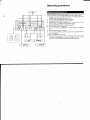
Operating procedures
26
Before turning the unit on, see that all controls and switches are pr
perly adjusted as recommended, especially the VOLUME control.
1. Be sure to turn the VOLUME control fully counterclockwise befot
operating any of the switches on the unit.
2. set the TAPE MONITOR switches to souRcE.
3. Set the SOURCE MONITOR switch to OFF.
4. Depending on the speaker systems (A or B) you wish to use, s
either or both of the SPEAKERS switches to ON.
5. Set the BALANCE control to its center position.
6. Set the TONE switch to DEFEAT.
-t.
Set the FILTER, LOUDNESS and AUDIO MUTING switchesl
OFF.
8. Set the MODE switch to STEREO.
9. Turn the MIC MIXING LEVEL control fully counterclockwise'
the "0" position.
10. Set the POWER switch to ON.
o For about 6 seconds after you've turned the unit on, no sound w
come from the speakers; the built-in protection circuit is at wo
until the circuits inside the unit are electrically stabilized.
.Proc6d6s de r6glage
Bed ienungsverf
Avant de mettre l'appareil en marche, prendre bien soin d ce que
toutes les commandes et interrupteurs soient mis sur une position
correcte de la fagon indiqu6e, surtout en cequiconcerne la commande
Vor dem Einschalten des Gerdtes unbedingt
VOLUME.
1. Prendre soin de bien tourner la commande VO LUME compldtement
dans le sens contraire des aiguilles d'une montre avant de manoeuvrer n'importe lequel des interrupteurs de l'appareil.
2. Mettre les interrupteurs TAPE MONITOR sur la position SOURCE.
3. Mettre l'interrupteur SOURCE MONITOR sur la position OFF.
4. Mettre I'un ou l'autre, ou les deux d la fois, des interrupteurs
SPEAKERS sur la position ON en fonction de quelles enceintes
acoustiques (A ou B) vous ddsirez utiliser.
5. Mettre la commande BALANCE sur sa position centrale.
6. Mettre l'interrupteur TONE sur la position DEFEAT.
7. Mettre les interrupteurs, FILTER, LOUDNESS et AUDIO MUTING
sur la position OFF.
8. Mettre l'interrupteur MODE sur
drehen, bevor irgendwelche andere Schalter des Geriites betdtigt
werden.
2. f
APE MONITOR Schalter auf Position SOUBCE stellen.
3. SOURCE MONITOR Schalter auf Position OFF stellen.
4. Abhdngig von den angeschlossenen Lautsprecherboxen (A oder B),
einen oder beide SPEAKERS Schalter auf Position ON stellen.
5. Den BALANCE Regler in seine Mittelstellung bringen.
6. Den TONE Schalter auf Position DEFEAT stellen.
7. FILTER, LOUDNESS und AUDIO MUTING Schalter
auf Position
OFF stellen.
8. Den MODE Schalter auf Position STEREO stellen.
9. Den MIC MIXING LEVEL Regler bis zu Position "O" gegen den
U
le
contraire des aiguilles d'une montre sur la position "0",
10. Mettre l'interrupteur POWER sur la position ON.
. Pendant environ 6 secondes aprds que vous ayez mis l'appareil en
marche, vous n'entendrez aucun son en provenance des enceintes
acoustiques: Le circuit de protection incorpord a 6td activ6 et fonctionne jusqu'e ce que tous les circuits, d l'intdrieur de l'appareil, se
trouvcnt 6lectriquement stabiliscs.
sens
darauJ achten, daB alle
Regler und Schalter gemdB Empfehlung eingestellt sind; besonders auf
die Einstellung des VOLUME Reglers achten.
1. Den VOLUME Regler bis zum Anschlag gegen den Uhrzeigersinn
la position STEREO.
9. Tourner la commande MIC MIXING LEVEL compldtement dans
ahren
hrzeigersinn drehen.
auf Position ON stellen.
Es dauert etwa 6 Sekunden nach dem Einschalten, bis die Lautsprecher in Betrieb gesetzt werden. Diese Zeitverzogerung wird
durch die eingebaute Schutzschaltung verursacht, die die Lautsprecherboxen erst einschaltet, wenn die elektrischen Schaltkreise
elektron isch stabi lisiert si nd.
1O. Den POWER Schalter
o
27
-
1. Turn the SELECTOR switch to PHONO-1 or -2,
2.
3.
whichever i
applicable for the turntable you wish to use.
OWrcte your turntable to play the records.
Adjust volume, balance and tone to your liking with controls arl(
switches on your unit.
Poor-quality record leproduction
10
*
*
Superlow-frequency noise, caused by warped or offcentered re
cords, forces the moving structure of a woofer to work excessively
such abnormal excursion generates distortion. To prevent sucl
noise, set the SUBSON lC FILTER switch to the ON position.
When you hear hum continuously, check the grounding of you
tu rntab le.
* You may hear howling or
@oo/K)\/o\)@oo@
3 O'"'O ff""':
FITTERS
SELECTOR
suBsoil rc
";f, g
-lm
P{oro 1'.-\'
\__/
acoustic feedback, caused when
wave
from the
avok
speakers,
and undesired signals are amplified. To
howling, move the turntable away from the speakers or install
*
tht
pickup of your turntable is affected by the vibrating sound
tht
turntable on a solid, non-resonating stand.
When you hear the irritating noise during record playback, it i
suggested that you check if there is dust accumulated on the surfao
of the record and on stylus tip. The cause may be a worn stylus tip
When you use a record cleaner, be sure to always use one of higl
quality.
'-
1. Tourner le commutateur SELECTOR sur PHONO-I ou -2 suivant
2.
3.
lequel est utilisable pour le tournedisque que vo_us voulez utiliser.
Faire fonctionner votre tournedisque pour 6couter les disques,
Rfulez le volume, l'6quilibrage et la tonalit6 suivant vos gouts per-
sonnels
d l'aide des commandes et interrupteurs de votre appareil.
1. Den SELECTOB Schalter auf PHONO-1 oder -2 drehen, je nachdem
an welche Klemmen der zu verwendende plattenspieler an-
2.
3.
Reproduction de disques de mauvaise qualit6
*
Les bruits parasites de trds basses fr6quences, causes par des disques
ray6s ou d6centr6s, entrainent une contrainte excessive des 6ldments
mobiles d'un woofer; cette contrainte provoque une distorsion
*
sonore. Pour 6viter un tel bruit, mettre l'interrupteur SUBSONIC
FILTEF sur la position ON.
Si l'on entend un ronflement r6gulier, v6rifier la mise 6 la terre du
tourne-d isque.
* On peut
entendre un hurlement ou une r6action acoustique, se
produisant lorsque le pick-up du tourne disque est affect6 par les
vibrations sonores provenant des enceintes acoustiques, et les
signaux ind6sir6s sont amplif i6s. pour 6viter le hurlement, 6loigner le
tourne disque des enceintes acoustiques ou installer le tournedisque
sur un support solide, exempt de r6sonance. On pourra en attdnuer
les effets 6galement si l'on place le tourne disque d l,un des coins de
*
6tre due
d
la pointe de lecture. Si l'on utilise un nettoyeur de
disque, ne pas manquer d'en trouver un de bonne qualit6.
Lautstarke, Balance und Klangfarbe mittels der Regler und Schalter
auf lhrem Geriite nach Wunsch einstellen.
Schallplattenwiedergabe schlechter Qualitiit
* Extrem tiefe Frequenzanteile, wie sie z.B. durch unebene Schallplatten erzeugt werden, verursachen groBe Schwingungsamplituden
in den Tieftonern der Lautsprecherboxen und fi.ihren damit zu Verzerrungen. Zur Vermeidung solcher Storungen, stellen Sie den
SUBSONIC FILTER
auf Position ON.
* Uberprilfen Sie beiSchalter
andauerndem Brummen die Erdung lhres
P lattensp ielers.
* Wenn der Tonabnehmer lhres Plattenspielers von den Schallwellen
der Lautsprecher beeinf luBt wird und diese unerwi.inschten Schwingungen \€rstarkt werden, kann es zu Heulen oder akustischer
Rilckkoplung kommen. Entfernen Sie zum Vermeiden von Heulen
den Plattenspieler von den Lautsprechern oder installieren Sie ihn
auf einem soliden, resonanzfreien Stand. Heulen kann auch durch
la piece.
Si l'on entend une un bruit d6sagr6able durant la reproduction d,un
disque, il est conseil16 verifier s'il n'y a pas de poussidre accumul6e
sur la surface du disque et sur la pointe de lecture. La cause peut
geschlossen ist.
Betreiben Sie den Plattenspieler zum Abspielen der Schallplatten.
Aufstellung des Plattenspielers in einer Ecke lhres Raums verringert
*
werden.
Pr[ifen Sie bei storgerduschen wdhrend der Wiedergabe von Schall-
platten auf Staubansammlung auf der Schallplatte oder an der
Nadelspitze. Eine weitere Ursache kann eine abgenutzte Nadel sein.
Verwenden Sie nur einen Schallplattenreiniger guter Oualitiit.
29
7
1.
2.
Set the SELECTOB switch to FM AUTO or AM (to FM AUTO t(
receive an FM broadcast, to AM to receive an AM broadcast).
Adjust the TUN ING control and tune in the desired station.
AM Rocoption
Optimal tuning is achieved when the rightmost SIGNAL indicato
light comes on.
FM Rocoptaon
30
Optimal tuning is achieved when the rightmost SIGNAL indicato
light and the round indicator light in the center of the TUNI
indicator come on. lf the left or right TUNE indicator light come
on, tuning has slipped somewhat. Turn the tuning control in th
direction pointed to by the triangular indicator light until the roun
TUNE indicator light comes on.
After optimal tuning is achieved,
the DIGITALLY
OUART
LOCKED System goes into operation to ensure continuousl
accurate tuning. The OUARTZ LOCKED indicator light showsthi
this system is in operation.
To tune in a weak-strength or fringe-area FM station, set the Fl
MUTING switch to OFF.
To receive a Dolbyized FM broadcast, set the DOLBY FM Dl
EMPHASIS switch to ON, turn on the Dolby NR (decoder) adaptr
you've connected to the TAPE-2 terminals on the unit, and set ti
TAPE MONITOR-2 switch to TAPE.
lf you haven't connectd a Dolby NR adaptor to the unit, but wa
to receive Dolbyized FM broadcasts, set the DOLBY FM 0
EMPHASIS switch to OFF; you can enjoy such broadcasts with
appreciable loss of high fedelity.
3. Adjust volume, balance and tone to your liking with controls ar
svvitches on your unit.
I
0 00 00
l^00
eo00\)g
FM
TODE
MUTITG
DOTBY F]S
OE-EMPHASIS
/J-l r r Dl sreaeo
0,,
[_[ | [J "*,
or
-
*;f,=
1. Stellen Sie den SELECTOR Schalrer aut FM AUTO oder auf AM
(fiir
2. Ajuster la commande TUNING et accorder sur la position
R6ception AM
2.
ddsiree.
L'accord est optimal lorsque la lampe la plus d droite du tdmoin
SIGNAL s'allume.
R6ctption FM
L'accord est optimal lorsque la lampe la plus d droite du t6moin
SIGNAL et la lampe ronde se trouvant au centre du tdmoin TUNE
s'allument. Si l'une des lampes droite ou gauche du temoin TUNE
s'allume, l'accord n'est pas parfait. Dans ce cas. tourner la commande d'accord dans le sens indiqu6 par la lampe triangulaire
s'6tant allum6e jusqu,d ce que la lampe ronde s,allume.
Une fois l'accord optimal obtenu,le systdme DIGITALLy
OUARTZ
LOCKED entre en action pour assurer la continuit6 de la pr6cision
de l'accord. Le t6moin OUARTZ LOCKED s,allume alors pour
r
r
3.
indiquer que le systdme fonctionne.
Pour 169ler une 6mission FM faible ou e la limite d,6mission, mettre
l'interrupteur FM MUTING sur la position OFF.
Pour pouvoir recevoir une 6mission FM Dolby-s6e, mettre le commutateur DOLBy FM DE_EMPHASIS sur la position ON, mettre en
marche l'adaptateur (ddcodeur) NB Dolby que vous avez raccord|
aux bornes TAPE-2 de l,appareil, puis mettre l,interrupteur TApE
l\4ONITOR-2 sur ta position TApE.
Si vous n'avez pas raccordd d,adaptateur NR Dolby d l,appareil.
mais
que vous vouliez recevoir des 6mission FM Dolby-s6es,
il faut mettre
le commutateur DOLBy FM DE-EMPHASIS sur la position
OFF;
vous pourrez alors profiter de ces 6missions sans perte sensible
au
niveau de la haute-f id6lit6
R6glez le volume, l'6quilibrage et la tonalitd suivant vos gouts per_
sonnels d l'aide des commandes et interrupteur de votre appareil.
-
UKW auf FM AUTO, fiir Mittelweile auf AM)
Mittels TUNING Knopf danach auf den Sender rhrer wahr abstim
men.
M
ittelwellenempfang
Optimale Abstimmung ist erreicht, wenn die duBerste rechte An
zeigeleuchte der SIGNAL Anzeige auf leuchtet.
UKW-Empfang
Optimale Abstimmung ist erreicht, wenn die euBerste rechte Anzeigeleuchte der SIGNAL Anzeige und die runde Anzeigeleuchte jn
der Mitte der TUNE Anzeige auf leuchten. Falls die rechte oder linke
Abstimmanzeigeleuchte aufleuchtet, ist die Abslimmung leicht
verschoben. Den Abstimmknopf in dje durch die Dreieckan,
zeigeleuchte angezeigte Richtung drehen, bis die runde Abstimmanzeigeleuchte auf leuchtet.
Nachdem optimale Abstimmung erreicht ist. wird das DIGITALLy
OUARTZ LOCKED System aktiviert, um eine unverenderr genaue
Abstimmung zu gewdhrleisten. Die OUARTZ LOCKED An_
zeigeleuchte zeigt den Betrieb dieses Systems an.
Wenn Sie auf einen schwach einfallenden bzw. entfernten
Sender
abstimmen wollen, den FM MUTING Schalter auf position
OFF
stellen.
Um ein dolbysiertes UKW-programm zu empfangen, den DOLBy
FM DE-EMPHASIS Schalter auf position ON stelten, den an die
T APE-2 Klemmen des Gerates angeschlossenen Dolby-NR-Adapter
einschalten und den TAPE MON ITOR_2 Schalter auf position
TApE
stellen.
Falls Sie keinen Dolby-NR-Adapter an das Gerdt angeschlossen
haben und ein dolbysiertes UKW-programm empfangen mochten,
den DOLBY FM DE-EMpHASIS Schalter auf position OFF stellen;
das UKW-Programm kann nun mit vernachldssigbaren eualitdtwer-
lusten empfangen werden.
Lautsterke, Balance und Klangfarbe mittels der Regler und Schalter
au{ lhrem Gerdte nach Wunsch einstellen.
3i
I
1.
2.
3.
TAPE
t
-:::
MO]IITOR
2
1.
)
to
:3"'6 O'u'OH4"
32
Set the SOURCE MON ITOR switch to OFF.
Push the TAPE MONITOR-I or -2 switch, whichever is applicable
for the tape deck you wish to use.
lf your tape deck has no Dolby facility, but the tape you wish to
play is Dolbyized, turn on the Dolby NR (decoder) adaptor you've
the unit's TAPE-2 terminals, and set the TAPE
connected
MONITOR-2 switch on the unit to TAPE.
Operate the tape deck to start playback.
Adjust volume, balance and tone to your liking with controls and
switches on your unit.
4.
5.
SOURCE
MoillToR
Poor-quality tape playback
High-freuqnecy hiss is a noise inherent in tape. Eliminate it with the
unit's HIGH FILTER switch. The noise increases when the heads of
your tape deck are magnetized. For elimination of such noise, refer to
f,-::::f,"::f,=
LcopYt>21
the instruction book of that tape deck.
I
F
L
L
a
t'
a
TAPE
I
n
MOilITOR
2
SOURCE
moillron
{[[
TAPE SOUBCE
OFF
(,,
TAPE TOTITOB
12
n
r0illT0B
quired.
h')
TAPE
-@!
f^^^A.
!rvvv.
TAPE-2
record/playback head, set the TAPE MONITOR saritch
to
SOURCE position and hear the sound before it is recorded.
Set the MODE switch to STEREO, when stereo recording
s0uRcE
tt -l- lt_
0Ff
SOURCE
-ffi-irln
oar.all
Prepare the program sour@ you wish to record and keep it ready to
go. The SELECTOR switch must be adjusted.
2. Operate the tape deck and start recording. Adjust the record levels
with controls provided on the tape deck. The volume and tone
controls on the unit do not affect the sound to be recorded.
3. To monitor the sound being recorded, follow the same procedure as
for playback after making certain that the tape deck itself is provided to permit monitoring. lf the tape deck only has a combined
(,,
the
is
re-
I
1
1
2
Mettre l'interrupteur SOURCE MONITOR sur la position OFF.
Enfoncer l'interrupteur TAPE MONITOR-l ou -2, suivant tequel
utilisable pour le magndtophone que vous voulez utiliser.
Si votre platine de magn6tophone n'est pas 6quip6e d'un dispositif
Dolby, mais que la bande que vous d6sirez passer soit elle DolbySe mettre en marche l'adaptateur (d6codeur) NR Dolby que vous
avez raccord6 aux bornes f APE-2 de l'appareil, et mettre l,interrupteur TAPE MONITOR-2 sur la position TApE.
Faire fonctionner le magn6tophone sur reproduction.
B69lez le volume, l'dquilibrage et la tonalit6 suivant vos gouts
personnels A l'aide des commandes et interrupteur de votre appareil.
est
4.
5.
Reproduction de bande de mauvaise qualit6
Le sifflement en haute frdquence est un bruit inh6rent d la bande.
L'6liminer avec l'interrupteur H IGH FILTER de l,appareil. Le bruit
augmente quand les tetes de la table de lecture sont magndtis6es. pour
l'6limination d'un tel bruit, se r6l6rer au livret d,instruction de cet
appa rei l.
1. Pr6parer la source de programme que l'on d6sire enregistrer et etre
pret au fonctionnement. Le commutateur SELECTOR doit €tre
169l6.
1. Den SOURCE MONITOR Schalter auf Position OFF srellen.
2. Danach den TAPE MONITOR-1 oder -2 Schalter drilcken,
je
nachdem an welche Klemmen das zu verwendende Tonbandgerat
angeschlossen ist.
3. Falls lhr
Tonbandgerat nicht mit Dolby ausgertistet ist, das abzuspielende Band jedoch mit Dolby aufgezeichnet wurde, den an
d ie
4.
5.
K
lemmen angesch lossenen Dolby-N
R
-Adapter ( Dekoder)
Tonbandwiedergabe schlechter Qualitdt
Hochfrequenzzischen ist eine Tonbdndern eigenttJmliche Storung. Be_
seitigen Sie es mit dem HIGH FILTER Schalter desGerdtes. Bei mag-
netisierten Tonkopfen des Tonbandgeriites erhohen sich die Storungen,
Beziehen Sie sich fiir die Beseitigung auf die Bedienungsanleitung des
Tonbandgerdtes.
l.
2. Faire fonctionner le magn6tophone et commencer l,enregistrement.
Ajuster les niveaux d'enregistrement e l'aide des diff6rents boutons
sur le magndtophone. Les boutons de volume et de tonalitd sur
l'appareil n'affectent pas le son d enregistrer.
3. Pour proc6der au contr6le du son en cours d'enregistrement, suivre
la mdme mdthode que pour la reproduction apres s,€tre assurd que
le magn6tophone lui-mdme est regl6 convenablement pour l,op6ra_
tion de contr6le sonore. Si le magndtophone ne possdde seulement
qu'une tete combin6e pour la reproduction/enregistrement, rdgler
l'interrupteur TAPE MONITOR sur la position SOURCE et ecouter
le son avant qu'il ne soit enregist16.
. Ouand vous d6sirez un enregistrement st6r6o, mettre l,interrupteur
MODE sur la position STEREO.
TAPE-2
einschalten und den TAPE MONITOR-2 Schalter des Gerdtes auf
Position TAPE stellen.
Betreiben Sie das Tonbandgerat fiir Wiedergabe.
Lautst6rke, Balance und Klangfarbe mittels der Regler und Schalter
auf lhrem Gerdte nach Wunsch einstellen.
Bereiten Sie die autzunehmende programmquelle vor und halten Sie
sie in Bereitschaft. Der SELECTOR Schalter muB entsprechend
eingestellt werden.
Betreiben Sie das Tonbandgeret und beginnen Sie mit der
Aufnahme. Stellen Sie die AuJnahmepegel mit den Reglern des
Tonbandgerdtes ein. Die Lautstdrke- und Tonregler des Gerdtes
beeinflussen den aufzunehmenden Ton nicht.
.1
Folgen Sie zum Mithoren des Aufnahmetons dem gleichen Ver_
fahren wie fUr Wiedergabe, nachdem Sie sich rergewissert haben,
daB das Tonbandgerdt fijr Mithoren eingerichtet ist. Wenn das
Tonbandgerdt nur einen Kombinationstonkopf fiir Aufnahme und
Wiedergabe hat, so stetlen Sie den TAPE MONITOR Schalter in die
Stellung SOUBCE, um den Ton zu horen, bevor er aufgenommen
wird.
Den MODE Schalter auf position STEREO stellen, wenn
Auf nahmen durchgeftihrt werden sollen.
Stereo_
33
TAPE
1
f_l
Il
MOl{ITOR
2
I
SOURCE
MOITITOR
1.
n
souRcg
l,J
OFF
------
-Z
lsuncr
-\il;p+;^llltr!+
it.@r rr '.th r
Dolby 1{R adsptol
AdaDtateur 0olby t{R
0olby-NR.AdapteI
(,,
TAPE.2
When you want
sound as
it's recorded on a nonbroadcasts but
haven't connected a Dolby NR adaptor, switch the DOLBY
EMPHASIS switch to OFF.
FM AUTO
1'l+-\'
to monitor the
Dolby tape deck while recording Dolbyized FM
SETECTOR
when re-
cording Dolbyized FM broadcasts.
To monitor your recordings of Dolbyized FM broadcasts as they are
made or before they are made, set the TAPE MONITOR switch to
TAPE or SOURCE. ln either position, the sound you hear is Dolbyized (undecoded). Therefore, when you want to hear the sound
decoded. turn on the Dolby NR (decoder) adaptor. connected to
the unit, then set the TAPE MONITOR-2 switch on the unit to
TAPE.
Prioilo-
1
2. Set the DOLBY FM DE-EMPHASIS SWitCh tO ON.
3. Operate the tape deck and start recording.
. lJ your deck has a built-in Dolby circuit do not use it
r _f l__L
TAPE TAPE
34
SEt thE SELECTOR SWitCh tO FM AUTO.
FIV DE-
AM
t^tr"*'-'@\
Push the TAPE MONITOR-1 switch. Do not push the TAPE
MONITOR-2 switch unless you wish to monitor the recording as
you record.
\-/
2. Play back the desired tape on the tape deck connected to TAPE-I,
it into the tape deck connected to TAPE-2.
While dubbing is undertaken, you can hear the program source
selected by the SELECTOR switch. When you want to hear records
or broadcasts, set the SOUBCE MONITOR siwtch to ON.
and record
MOTITOR
2
I-
s0 uRcE
(,,
s0u RcE
MOI{ITOR
M01{tT0R
A
[-
0lll
OFF
.
-\.
fti'r:--n :rr['r']
ilL:(,-€loo""':lf
TAPE-1
IAPE.2
-----r!
l.
Mettre lecommutateur SELECTOR sur la position FM AUTO.
2. Mettre l'interrupteur DOLBY FM DE-EMPHASIS sur la position
1
2
oN.
oN.
3.
.
4.
r
Faire fonctionner le magn6tophone et commencer l'enregistrement.
Si votre magndtophone est 6quipd d'un systeme Dolby incorpord,
ne pas l'utiliser quand vous procddez d des enregistrements d'6missions FM Dolby-s6es.
Pour contr6ler vos enregistrements d'6missions FM Dolby-s6es au
fur et d mesure qu'ils sont effectu6s, ou m€me avant qu'ils soient
eJfectuds, mettre l'interrupteur TAPE MONITOR soit sur la position
3
a
TAPE-2.
Ouand le copiage de bande est en train, vous avez la possibilitd d'entendre la source de programme s6lection6e, en actionnant le commutateur SELECTOR. Ouand vous ddsirez entendre des disques ou
des 6missions de radio, il faut mettre l'interrupteur SOURCE
MONITOR sur la position ON.
Betreiben Sie das Tonbandgerat und beginnen Sie mit der Aufnahme.
Fal ls I hr Tonbandgerat m it Dolby-R auschunterd r0ckung ausgeriistet
ist, diese nicht einschalten, wenn dolbysierte UKW-Programme
mitgerhnitten werden.
Um die Aufnahme von dolbysierten UKW-Programmen mitzuhoren,
den TAPE MONITOR Schalter entweder auJ Position TAPE (Hinter-
bandkontrolle) oder auf Position SOURCE (Vorderbandkontrolle)
stellen. ln beiden Fdllen wird jedoch nur das dolbysierte (nicht
dekodierte) Programm vernommen. Falls Sie daher das dekodierte
TAPE ou sur la position SOURCE. Sur ces deux positions, le son
que vous entendez est Dolby-s6 (non ddcod6). Par consdquent, si
vous d6sirez entendre un son d6cod€, mettre en marche l'adaptateur
(ddcodeur) Dolby NR raccord6 d l'appareil,puis mettre l'interrupteur
TAPE MONITOR-2 de l'appareil sur la position TAPE.
Ouand vous voulez controler le son au fur et d mesure qu'il est
enregistr6 sur un magndtophone non 6quipd d'un systdme Dolby
tout en enregistrant des 6missions FM Dolby-s6es mais sans avoir
raccord6 un adaptateur Dolby NR, mettre l'interrupteur DOLBY
FM DE-EMPHASIS sur la position OFF.
Enfoncer l'interrupteur TAPE MONITOR-1. Ne pas utiliser l'interrupteur TAPE MONITOR-2 a moins que vous vouliez contrOler
l'enregistrement au fur et a mesure que vous enregistrez.
Reproduire la bande que vous d6sirez sur le magn6tophone raccord6
sur TAPE-I, et l'enregistrer sur le magndtophone raccord6 sur
Stellen Sie den SELECTOR Schalter auf Position FM AUTO.
Stellen Sie den DOLBY FM DE-EMPHASIS Schalter auf Position
Programm horen mdchten, den an das Geret angerhlossenen
Dolby-NR-Adapter (Dekoderl einschalten und den TAPE MONITOR-2 Schalter auf Position TAPE stellen.
Wenn Sie die Aufnahme von dolbysierten UKW-Programmen auf
einem Tonbandgerdt ohne Dolby-Rauschunterdriickung mithoren
mcjchten
und kein Dolby-NR-Adapter angerhlossen ist,
den
DOLBY FM DE-EMPHASIS Schalter auf Position OFF stellen.
1.
2.
Den TAPE MONITOR-1 Schalter dri.icken; jedoch nicht den TAPE
MONITOR-2 Schalter betatigen, wenn Sie nichr gleichzeitig mit der
Aufnahme das aufgenommene Tonmaterial mithoren mochten.
Das gewiinschte Band auf Tonbandgerdt TAPE-I auflegen und die
Wiedergabefunktion einstellen; das an
o
f APE-2
angeschlossene
Tonbandgerat auf Aufnahme stellen, um das Tonband zu kopieren.
Unabhdngig vom Uberspielen von Tonbdndern kann auch die mittels
SELECTOR Schalter gewehlte Programmquelle gehort werden.
Wenn Sie z.B. Schallplatten reproduzieren bzw. Rundfunkprogramme empfangen mdchten, den SOURCE MONITOR Schalter
auf Position ON stellen.
35
-
o@
@o
1. lnsert the microphone plug into the MIC jack on the front panel'
2. Adjust the level of microphone sounds with the MIC MIXING
LEVEL control.
signals with other program sources (records,
or tapes), set the SELECTOR and/or TAPE MONITOR
sritch(es) to the source you want to mix with and then turn the
VOLUME control to adjust the level of the program source to
match with the level of mic signals. When using the microphone
only with no mixing, turn the VOLUME control fully counter-
3. When mixing mic
broadcasts
36
o
\
/
clockwise.
When inserting or removing the microphone plug, turn the MIC
MIXING LEVEL control fully counterclockwise first.
About microphones
It is recommended to
: H"3
O'"'O U".':
Howling while using a microPhone
t>+
\fl/
-
50kf!) microuse a high-impedance ('lOk!-}
phone, although a low-impedance one (6O0O) will be more effective if
you wish to use it several meters away from the unit. lf using a lowimpedance one with a small output (such as a dynamic type lowimpedance microphone), you'll need a matching transformer between
the microphone cord and the unit's MIC jack.
Loud oscillating noise may be heard from your speaker systems when
using a microphone. This is a phenomenon called howling, and happens
because the sound from your speakers is fed back to the microphone
and amplified again, repeating the process infinitely. lt is more likely to
take plac€ in an acoustically reflective room especially if you raise the
sound volume.
It can be avoided either by directing or moving the microphone away
from the speaker systems.
1. ln#rer
la fiche de microphone dans la prise jack MIC sur le panneau
1.
Regler le nlveau de volume pour la voix en tournant la commande
MIC MIXING LEVEL dans le sens des aiguilles d'une montre.
Ouand vous procddez d des mdlanges de signaux en provenance d'un
microphone avec d'autres sources de programme (disques, 6missions
radio ou bandes), mettre les commutateurs SELECTOR et/ou TApE
MONITOR, sur la position de la source que vous voulez mdlanger,
puis tourner la commande VOLUME sur une position telle qu'elle
s'accorde avec le niveau des signaux en provenancedu microphone.
En cas de non mixage, tourner la commande VOLUME d fond dans
le sens contraire des aiguilles d'une montre.
En insdrant et en tirant la fiche de microphone, tourner la commande MIC MIXING LEVEL d fond dans le sens contraire des
aiguilles d'une montre.
2.
avan
2.
3.
o
t.
Concernant le microphone
ll est recommand6 d'employer un microphone de haute imp6dance
(1OkO - 50kO), quoique une faible imp6dance (600O) sera plus
eJficace si l'on d6sire l'utiliser d plusieurs mdtres de I'appareil. Ouand on
emploie un micro d faible impddance et de faible sortie (tel qu'un
microphone d faible impddance du type dynamique), il faudra recourir
d un transformateur assorti entre le cordon de microphone et la prise
jack MIC de l'appareil.
Hurlement durant l'emploi ou microphone
Un bruit oscillant 6levd peut se faire entendre dans les haut-parleurs
lorsqu'on utilise un microphohe. Ce ph6nomdne est appeld hurlement,.
se produit parce que le son des haut-parleurs r6agit sur le microphone
puis est 'amplif6 A nouveau, r6pdtant le processus ind6finiment. Cela
risque plut6t de se produire dans une pidce d 6cho acoustique et en
particulier si l'on augmente le volume sonore.
On pourra y remddier soit en dirigeant ou en d6plagant le microphone
hors de port6e du haut-parleur.
et
Schieben Sie den Mikrofonstecker
derseite des GerStes.
in die MIC Buchse an der Vor-
Regeln Sie den Mikrofonpegel durch Drehen des MIC MIXING
LEVEL Reglers.
3. Ftir Mikrofonzumischung zu anderen Programmquellen (Schal,lplatten, Rundfunkprogramme oder Tonbandwiedergaben) den
SELECTOR und/oder TAPE MONITOR Schalter auf die ent-
.
sprechende Programmquelle einstellen; den VOLUME Regler so einjustieren, daB der Lautstdrkepegel der Programmquelle an den pegel
der Mikrofonzumischung angepaBt ist. Wenn Sie nicht mischen, so
drehen Sie den VOLUME Regler ganz nach links.
Drehen Sie beim Einschieben und Herausziehen des Mikrofonsteckers den MIC MIXING LEVEL Regler ganz nach links.
Zum Mikrofon
Es wird empfohlen, ein Hochimpedanzmikrofon (1OkA bis 50kA) zu
rrerwenden, aber ein Niederimpedanzmikrofon (600fl) ist wirksamer,
wenn Sie es einige Meter vom Gerat entfernt verwenden wollen. Bei
Verwendung eines Niederimpedanzmikrofons (2.8. ein dynamisches
Niederimpedanzmikrofon) brauchen Sie einen AnpaBtransformator
zwischen dem Mikrofonkabel und der Mikrofonbuchse des Gerates.
Heulen bei Verwendung eines Mikrofons
Bei Verwendung eines Mikrofons kann es zu Iauten Oszillationstonen
aus dem Lautsprechersystem kommen. Dieses phdnomen wird Heulen
genannt und tritt auf, wenn der Ton von lhren Lautsprechern ins
Mikrofon gelangt, wieder verstdrkt wird, und sich dieser Vorgang
unbegrenzt wiederholt. Es tritt hauptsdchlich in akustisch reflektierenden Rdumen auf, besonders bei groBerer Lautstdrke. Es kann durch
Wegdrehen oder Wegbewegen des Mikro{ons von der Lautsprecheranlage verhiitet werden.
Q-7
-
Some useful hints
Compared with AM, FM is inherently of higher quality with less noise
and less interferences. Here are some hints for further improved FM
JO
reception.
Multi-path phenomenon and antenna alignment
FM waves are directional (more directional than AM), possessing a
tendency to beam in a straight line. When hitting an obstacle, they
simply reflect. Antennas receive the waves reflected by nearby obstacles (such as mountains or tall buildings) as well as the wave beamed
direct from the station. The result is a multi-path phenomenon, the
same problem as the cause of "ghosts" on TV screen. ln FM, reflection
can cause distortion and poor stereo separation. Use an FM antenna
with good directionality and align it correctly to minimize such distortion antenna input-When antenna input is too weak, the signal-tonoise ratio (the relative levels of the desired vs. the noise generated
inside the unit and by extraneous signals) may deteriorate. The causes
Wek
may be:
*
*
lmproper antenna location.
of a low-gain T-shaped antenna. (Replace
Use
antenna.
a ---' Multi-path
phenomenon
Ph6nomdne e
multi-trajets
Mehrwegphanomen
it with
an outdoor
)
Noarby el€ctric appliances-Pulsive noises, caused by electrical sparks,
may be mixed into audio signals. Major sources of such noises are
automobiles (ignition plugs), electric trains, high-tension lines, fluorescent lamps, welding machines, etc. Therefore, you suffer less noise
when the antenna is placed as far away as possible from such sources of
noise.
E
Quelques conseils utiles
Einige ni,itzliche Hinweise
Compar6e ii la rdception AM, la FM est fondamentalement de meilleure
qualit6 avec moins de bruit et moins d'interfdrences. Voici quelques
conseils utiles pour amdliorer la r6ception FM.
Ph6nomCne a multi-traiots et alagnoment d'antenne
Les ondes FM sont directionnelles (plus directionnelles qu'en AM), elles
ont tendance d se propager en ligne droite. Ouand elles rencontrent un
obstacle, elles sont simplement r6fl6chies. Les antennes reqoivent les
ondes r6fl6chies par les obstacles alentours (tels que les montagnes et les
bdtiments 6lev6s) ainsi que les ondes provenant directement de la
station dmettrice. Le rdsultat est un phdnomdne a multi-trajets le m€me
probldme qui cause des images fant6mes sur l'dcran de t6ldvision. En
FM, la r6flexion peut produire des distorsions et une mauvaise sdparation st6r6o. Utiliser une antenne FM avec une bonne directionalit6 et
l'aligner correctement pour minimiser une telle distorsion.
Entr6o d'antonne faible-Si l'entrde d'antenne est trop faible, le rapport
de signal d bruit (la diff6rence entre le niveau d6sird et le bruit engend16
a l'int6rieur de l'appareil etpar les signaux externes) peut dtre diminu6.
Les causes
peuvent etre.
* Mauvais emplacement de l'antenne.
* Emploi d'une antenne en T d faible gain.
(Remplacer par une
antenne extdrieurel.
Appareils 6lectrklues fonctaonnant il proximit6-Les parasites d impulsions provoquds par les dtincelles 6lectriques, peuvent 6tre m6lang6s aux
signaux audio. Les sources principales de tels bruits sont les automobiles (bougies d'allumage) , les trains 6lectriques, les lignes de haute
tension, les lampes fluorescentes, les machines d souder, etc, par conSquent, on obtiendra moins de bruit si l'antenne est plac6e le plus loin
possible de telles sources de bruit.
lm Vergleich zu Mittelwelle hat UKW eine viel hohere Oualitdt mit
weniger Storungen und weniger lnterferenz. Hier sind einige Hinweise
zur weiteren Verbesserung des U KW-Empfangs:
Meh rwegphSnomen und Antennenausrichtung
UKW-Wellen haben Richtwirkung (mehr als MW-Wellen) und breiten
sich geradlinig aus. Wenn sie auf ein Hindernis treffen, werden sie
ref lektiert. Antennen empfangen die von Hindernissen in der Ndhe
(Berge, Hochhduser usw.) ref lektierten Wellen genau so wie die direkt
vom Sender ausgestrahlten Wellen. Das Ergebnis hiervon ist das
Mehrwegphdnomen, das gleiche Problem, das beim Fernsehen zu
Geisterbildern fiihrt. Bei UKW kann Reflexion zu Verzerrung und
schlechter Stereotrennung fr"ihren. Verwenden Sie eine UKW-Antenne
mit guter Richtwirkung und richten Sie sie genau aus, um solche Verzer(ung auf ein Minimum zu bringen.
Schwacher Antenneneingang-Wenn der Antenneneingang zu schwach
ist, kann der Signal-Rauschabstand (das Verhdltnis von gewi.inschtem
Ton zu Storungen durch das Gerat selbst und durch duBere Ursachen)
verringert werden. Die Ursachen konnen sein:
* Falscher Antennenanbringungsort.
* Verwendung einer T-formigen Antenne. (Ersetzen Sie sie durch eine
AuBenantenne.)
Elektrogerdte in der Ndhe-Durch Funken verursachte, pulsierende
Storungen konnen sich mit den Audiosignalen mischen. Die Hauptquellen ftir solche Storungen sind Autos (Zr.indkerzen). Elektrozi]ge,
Hochspannungsleitungen, Leuchtstoff lampen, SchweiBgeriite usw. Aus
diesem Grund erhalten Sie weniger Storungen, wenn die Antenne so
weit wie moglich von solchen Storungsquellen entfernt angebracht
wird
-
39
---------
c
40
{,
@
o
@
Following are some hints for better AM reception.
{
r)
When receiving weak stations:
When the unit is tuned to a weak AM station, you hear lower volume
then when it receives a strong one. This may be corrected by re-aligning
the rear-panel AM ferrite bar antenna. lf the unit is used in a concrete
building, AM volume may be increased by placing it by a window. For
best AM reception, you are advised to install an outdoor AM antenna.
When hearing AM noise:
AM noise can be caused by one of the following reasons.
lnterference-lnterference causes an audible, highpitched beat. To
avoid it, re-align the direction of the antenna. Also note that an
outdoor antenna may also increase the noise level of a desired station
by accidentally pulling in interference from other stations. Re-alignment in this case is also necessary.
Hum- Booming hum noise is often caused by the power source and is
heard as 60 Hz (or 50 Hz) sound. lt may be reduced by moving the unit
away from other electric appliances.
Buzz-Bvzz noise is caused by fluorescent lamps and other electric
appliances, or by natural phenomena such as thunder. lnstallation of a
noise-suppression device may be effective. Since complete elimination
of AM buzz is usually impossible, it is suggestd that you make it less
audible with the high filter or treble tone control on your unit.
-
Voici quelques conseils utiles pour une meilleure r6ception AM.
Nachfolgend
En recevant des stations faibles:
Beim Empfang schwacher Sender:
Wenn das Gerat auf einen schwachen MW-Sender abgestimmt ist,
Si l'appareil est accord6 sur une station AM faible, on entendra un
volume plus faible que lorsqu'on regoit une station plus forte. On
pourra y remddier en rdalignant l'antenne d barreau de ferrite AM
du
panneau arridre. Si l'appareil est utilisd dans un b6timent en
b6ton
armd, le volume AM pourra etre accentu6 en plagant I'appareil prds
d'une fenetre. Pour la meilleure rdception AM possible, il est conseilld
d'installer une antenne AM ext6rieure.
suivantes.
lnbrf6renc6-Les interfdrenc€s produisent un battement audible
d
n6cessaire.
Ronflement-Un bruit de ronflement fort est souvent produit par
ll
fiir
besseren MW-Empfang.
41
so
horen Sie eine geringere Lautsterke als bei einem starken Sender. Dies
kann eventuell durch Ausrichten der Ferritstabantenne an der Riickseite
des Geretes beseitigt werden. Wenn das Gerdt in einem Stahlbetongebdude verwendet wird, kann die Mw-Lautst6rke durch Aufstellung
des Gerdtes in der Nahe eines Fensters verbessert werden. Frir besten
wird die Verwendung einer
MW-Auf3enantenne
empfohlen.
Beim Auftreten von MW-Sttirungen:
die folgenden Ursachen verursacht
MW-Storungen konnen durch
haute tonalit6. Pour l'6viter, rdaligner la direction de l,antenna. Noter
6galement qu'une antenne extdrieure risque aussi d,augmenter le niveau
de bruit d'une station d6sir6e en captant accidentellement les interf6rences d'autres stations. Le rdalignement dans ce cas s,avdre aussi
la
peut
Gr6sillomont-Le bruit de grdsillement est produit par les lampes
fluorescentes et autres appareils dlectriques, ou par des ph6nomdnes
naturels tel que la foudre. l'installation d'un dispositif anti-parasite peut
6tre efficace. Etant donnd que l'dlimination compldte du grdsillement
AM est normalement impossible, il est conseilld de le rendre moins
audible au moyen du bouton de tonalitd aigu6 ou de filtre haut sur
l'appareil.
inden Sie einige Hinweise
MW-Empfang
S'il y a du bruit en AM:
Du bruit dans les 6missions AM peut etre d0 A l,une des raisons
source de puissance et se fait entendre sur 5O Hz (ou 60 Hz).
dtre rfuuit en 6loignant l'appareil des autres appareils dlectriques.
f
werden.
I nterferenz- I n terf erenz veru rsacht ein horbares ho hes pfeif en. R ichten
Sie zur Vermeidung von lnterferenz die Antenne neu aus. Beachten Sie
bitte, daB eine AuRenantenne auch den Storungspegel eines gewiinschten Senders durch ungewolltes Auffangen von lnterferenz anderer
Sender verol3ern kann. Auch in diesem Fall ist Neuausrichtung
erforderlich.
Brummen-Lautes Brummen wird
oft durch die Netzfrequenz
ver-
ursacht und als Ton von 50 Hz (6O Hz) geh6rt. Es kann eventuell durch
Entfernen des Gerdtes von anderen Elektrogeraten.
Summsn-Summen wird,dtrrch Neonlampen und andere Elektrogerete
oder durch Naturerscheinungen wie Blitze verursacht. Die lnstallierung
einer Ents6rvorrichtung kann hilfreich sein. Da vollstdndige
Beseiti-
gung von MW-Summen normalerweise unmoglich ist, sollten Sie esmit
dem HochpaBregler oder Hochtonklangregler lhres Geretes weniger
horbar machen.
-
"AUX"
means auxiliary, and
the TAPE/AUX inputs have the
same
electrical function as the TAPE PLAY inputs. They therefore connect a
tape deck, an adaptor for special cartridges, and other equipment that
has about the same output level as the afore-mentioned components'
42
Tape-to-tape coPying
. set the SELECTOR switch to the TAPE/AUX position when you
are dubbing a tape deck (in playback mode), connected to the
TAPE/AUX terminals, onto another tape deck (in record mode),
connected to the TAPE R EC terminals.
0 00 00 A00l^
00 000
@OBOL/o\rQooo
lf the speaker cords are shorted, if the unit operates abnormally or if
the sound is louder than the rated level, the built-in protection circuitry
is actuated and the sound will be cut off. ln cases like this, quickly set
the POWER switch to OFF, eliminate the cause of the actuation, and
then reset the POWER switch to the ON position' lf this protection
circuitry still continues to work, disconnect the power plug and call
your dealer or the nearest Sansui Authorized Service Station.
o The SAFELY OPERATE indicator will go off'when the protection
circuitry
*
is actuated.
lnstructions and requirements indicatd may vary
depending on sales area, local laws and regulations.
to
some extent
-
"AUX" signifie auxiliare, les entr6es TAPE/AUX ont la meme fonction
el6ctrique que les entrdes TAPE PLAY. Elles servent a brancher un
magndtophone, un adaptateur pour cartouches spdciales et d'autres
6quipements qu; ont d peu prds la mdme puissance que les composants
mentiones cidessus.
i
Copiage de bande bande
o R6gler le commutateur SELECTOR sur la position TAPE/AUX
lorsqu'on proc6de au copiage avec un magn6tophone (au mode
reproduction), connect6 aux bornes de TAPE/AUX, sur un autre
magndtophone (au mode d'enregistrement), connectd aux bornes
Die mit TAPE/AUX bezeichneten Reserveeingdnge haben die gleiche
elektrische Funktion wie die TAPE PLAY Eingiinge. Daher kcinnen an
diese Eingdnge ein Tonbandgerat, ein Adapter fUr Tonabnehmer oder
ein anderes Gerdt (mit ungefar dem gleichen Ausgangspegel, wie die
vorher erwiihnten Kompo nenten ) angesch lossen werden.
Uberspielen von Tonbdndern
. Stellen Sie
den SELECTOR Schalter in die Stellung TAPE/AUX,
wenn Sie von einem an die Klemmen TAPE/AUX angeschlossenen
Tonbandgeret (in Wiedergabe) auf ein an den Klemmen TAPE REC
angeschlossenes Tonbandgerdt (in Aufnahme) tiberspielen wollen.
deTAPE REC.
Falls die Lautsprecherkabel kurzgeschlossen sind, das Gerdt fehlerhaft
Si les cordons des enceintes sont en court-circuit, si l'appareil fonctionne de fagon anormale ou si le son est plus fort qu'il ne devrait
l'6tre, le circuit de protection incorpor6 sera alors activ6 et le son sera
coup6. Dans un tel cas, mettre rapidement le commutateur POWER
sur OFF, 6liminer les causes du mauvais fonctionnement puis remettre
l'interrupteur POWER sur ON. Dans le cas ori le circuit de protection se
trouve toujours en action, ddbrancher le cordon d'alimentation et
appelez votre marchand ou le plus proche concessionnaire autorisd
Sansui
.
arbeitet oder der Ton lauter als die Nennleistung ist, schaltet sich die
eingebaute Schutzschaltung ein, und der Ton wird unterbrochen. ln
solchen Fdllen den POWER Schalter schnell auf OFF stellen, die
Storung beseitigen, und den POWER Schalter wieder auf ON stellen.
Falls sich die Schutzschaltung weiterhin einschaltet, den Netzstecker
herauviehen, und lhren Fachhdndler bzw. die ndchste autorisierte
kontaktieren.
OPERATE Anzeige erlischt, wenn sich die Schutz-
Sansu i-Kundend ienststation
. Die SAFELY
schaltung einschaltet.
Le voyant SAFELY OPERATE s'dteindra quand le circuit de protection est activ6.
* Les instructions et
les rdglementation
in
diqudes peuvent varier
suivant la 169ion, les lois et les rdglements locaux.
Die Anleitungen und angegebenen Werte konnen in Abhdngigkeit
vom Verkaufsgebiet und den ortlichen Gesetzen etwas abweichen.
43
-
Specifications
Audio section
Power output
Min. RMS, both channels driven, from 20 to 20,000 Hz,with no more
than 0.025 % total harmonic distortion.
1 20 watts per channel into 8 ohms
B ohms
Load impedanca
. less than O.O25o/o at or below
Total harmonic distortion
rated min. RMS power output
lntermodulation distortion OO Hz : 7 k{z = 4:1 SMPTE method)
less than O.O25 o/o at rated
power output
44
Il_I!:
o
o
iiri ?
vo
/-\ fA.;
cijiii.
o
^
.-- U
- --a
."*,.
o cHA
[,
o cHa
Ftr- 3
+
O::: OO
u,,ou,o
o"
E I
o
IPD SIONI
-\o
of " 1
o*:-o
o 90
0 00
00
Rbs tim€
'l
000
Slew rate
Frequency rssponse ("t t *uttj
Overall (from TAPE/AUX)
60 V/psec
0000000
"o
-:=
Power amplifier
I
I
*EUU
@_o
EOODE
(o) o@
/',,A\,;'
((
))@
\v/-
.
5 to 75,00O Hz,
+0.2 dB, -2.0 dB
DCto 2OOkHz,
+0 dB. -3.0 dB
RIAA curve dwiation (PHONO, 20 Hz to 20 kHz)
+0.2 dB.
-0.2 dB
Danrplng factor (20 Hz to 20 kHz, both channels driven)
.
.... SOintoSohms
lnput sensitiyaty and impedance (at 1 kHz)
.... 2.5mV/4Tkilohms
PHONO-1,2 ...
(Max. input capability: 250 mV at 1 kHz, less than 0.1 % total
harmonic distortion)
MIC ..
....6mV/l0kilohms
TAPE-1,2PLAY,TAPE/AUX . . . 150mV/47 kilohms
Output level (at 1 kHz)
TAPE-I .2 REC
-
.
.4 psec
15O
mV
Sp6cif ications
Section audio
Audioabschnitt
Puissance de sortie
Puissance efficace minimale, les
deux canaux en fonction, de 2O it
20.000 Hz, avec pas plus de 0,025 % de distorsion harmonique totale.
1 20 watts par canal avec 8 ohms
lmp6danca de charge
8 ohms
Distorsion harmonique totalo .
moins de 0,02b % juste ou en
dessous de la puissance de
sortie minimale eff icace.
o'":*':i
Temps
1''*:--'::':l
l':': ] ff; :
J
Jrl!?:".
?y
".,
puissance de sortie nominale
1 ,4 psec
d'6l6vation
Tempsdepivotago. .
:.
Globale (depuis TAPE/AUX)
.
.
fonction)
?t
...
20 kHz,les deux canaux en
soavecSohms
lmp6danco et sensibalit6 d'ontr6e (d 1 kHz)
,2.......
2,5 mV 147 kiloohms
(Capacitd d'entr6e rnu".' ZSO
-V A 1 kHz moins de O,1 o/o de
distorsion harmon ique totale)
PHONO-I
MIC..
TAPE.I ,2PLAY, TAPE/AUX
Niveau de sortie (d 1 kHz)
TAPE-I
,2 REC
.
Nen nausgangsleistu ng
17
O
6 mV/l0 kiloohms
15O mY /47 kiloohms
150 mV
Hz :7 kHz = 4:1 SMPTE Method)
.
Frequenzgang (bei 1 W)
I nsgesamt (von TApE/AUX)
CC d 200 kHz,
+0 dB.
-3.0 dB
(PHON O, 20 Hz, it 2O k1zl
+O,2 dB, _0,2 dB
.
Coefficient dhmortissoment QO Hz
lntermodulationwer.€rrung
5 d 75.000 Hz,
+0,2 dB,
-2,O dB
IAA
unter min. effektiver
Einschwingzeit
Schwenkbetrag
Amplificateur de puissance de l'appareil
R
Ausgangsleistung
Min. effektive, beide Kandle betrieben, von 20 bis 2O.OOO Hz, mit
nicht mehr als 0,025 o/o Klirrgrad
12OW pro Kanal an 8 Ohm
Lastimpedanz
. 8Ohm
Klirrgrad
. weniger als O,025 % bei oder
60 V/psec
R6ponse de fr6quence (A 1 watt)
D6viation de la courbe
-
Technische Daten
weniger als 0,025
N en nau sgangsle
1
,4 psek
..
6OV/psek
.
..
+02 dB, -2,0 dB
DC bis 2OO kHz,
.
Leistungsverstdrker.
7o bei
istung
5 bis 75.000 Hz,
+0d8,-3.0d8
RIAA-Kurvenabweichung (PHONO,20 Hz bis 20 kHzl
...+ozdB,_02d8
Dimpfungsfaktor l2O Hz bis 20 kHz, beide Kan6le betrieben)
einengsempiinirilr"i unj r-p"j"n.,33'
,2
i"rt":i'n
PHONO-I
2,5 mV/47 Kitoohm
(Max. Eingangskapazitat: 2S0 mV bei 1 kHz,weniger alsO,1
Klirrgrad)
Mtc ..
....6mV/l0Kitoohm
TAPE-I ,2 PLAY,TAPE/AUX
Ausgangspegel (bei 1 kHz)
TAPE-I ,2REC
..
.
150 mV/47 Kitoohm
150 mV
vo
45
-
Hum and noise (shortcircuit, A-network)
PHONO-1
,2 ...
....78d8
TAPE.1 ,2PLAY, TAPE/AUX
Channel s€paration (at 1 kHz)
PHONO-1,2
TAPE-I ,2PLAY, TAPE/AUX
Controls
BASS
TREBLE
SUBSONIC FILTER
H IGH F ILTER
46
..
.
95 dB
..
.
60 dB
65 dB
t
l"ll'l'
AUDIOMUTING
....
FM section
\'
,-*
flo[I
ut
EA
ODo
O
+
+
@@s
O" O o O
rar4e
Usable
:ensitivity
dB At 10 KHZ
. . . -3 dB at 16 Hz (6 dB/oct)
-3 dB at 3 kHz (6 dB/octl
'o'.o*": lY:i:Y:
Tuning
10 dB at 5O Hz
T 1O
..
:oro5J:;';fll.
6dB at 10 kHz
-2OdB
.
88
to 108 MHz
MonolHF
...g.BdBf(1.7pV)
DlN...
......1.0pV
Stereo IHF
. . 17 dBf
50 dB quieting semitiyity
Mono
......14d8f
Stereo
....36dBf
Signal to noiss ratio (at 65 dBf )
Mono
.....76d8
Stereo
....71dB
Distortion (at 65 dBf )
Mono
less than 0.1 Yo at 1OO Hz
than O.1 Yo at 1,0O0 Hz
lessthan O.25%at 6,00O Hz
less
Stereo
..
.
less
less
less
Alternate channel selectivity (at 400 kHz)
.
than O.23 % at 1N Hz
than O.'15 % at 1 ,0O0 Hz
than O.23 % at 6,000 Hz
70dB
-
Ronflement et bruit (lH F )
PHONO-1, 2
TAPE-I, 2 PLAY, TAPE/AUX
Sdparation de canaux (d 1 kHz)
PHONO-1, 2
TAPE-I ,2 PLAY, TAPE/AUX
Kanaltronnung (bei 1 kHz)
PHONO-l,2
60 dB
65 dB
TAPE-I ,2 PLAY, TAPE/AUX
F
.
...
1'::'::::::.:
78 dB
95 dB
.
60 dB
65 dB
..
d'accord
_2OdB
AUDIOMUTING
88 d lO8 MHz
Sensibilit5 utilisable
MonolHF
DlN...
...g,BdBf (1,7pV)
1,0 pV
17 dBf
Stdr6o IHF
Seuil de sensibilit6 50 dB
Mono
bruit
10 dB bei 50 Hz
-3dB
UKW-Abschnitt
Empfangsbereich
E
.,..
bei
3kHz (6dB/Oktave)
bei50 Hz
6 dB bei 10 kHz
_2OdB
....88bis108MH2
ingangsempf indlichkeit
Mono IHF
DIN
Stereo IHF
98 dBf
1,0 pV
I't ,7
pvl
17 dBf
50 dB-Empf indlichkeitsschwelle
14 dgf
36 dBf
.
Rapport de signal e
Mono
I
... rlodBbeilokHz
. . . -3dB bei 16 Hz (6dB/Okrave)
'o'o*':: lY:::Y: ?*:":. ':i?B
d 50 Hz
6dBA10kHz
Section FM
Stdrdo
BASS
TREBLE
SUBSONIC FILTER
HIGH FILTER
t10dBd lOkHz
-3 dB a 16 Hz (6 dB/oct)
-3dBa3kHz (6dB/oct)
-ro3l
AUDIOMUTING .. .
Echelle
..
...
Regler
110 dB A 50'Hz
ILTER
HIGH FILTER
'o.'o"::
,2
78 dB
95 dB
TAPE-l, 2 PLAY, TAPE/AUX
Commandes
BASS
TR EBLE
SUBSON lC
Brummen und Rauschen (lH F)
PHONO-I
(a 65 dBf
Mono
Stereo
Mono
Stereo
76 dB
71 dB
Dinorsion harmonique totale (d 65 dBf)
Mono
Stdr6o
Klirrgrad (bei 65 dBf)
moins
moins
moins
moins
moins
de
de
de
de
de
o/o
A 1OO Hz
0,1 % d 1.000 Hz
O,25 % A 6.000 Hz
O,23 o/o A 1OO Hz
O]5o/o d 1.00O Hz
moinsde O,23o/oA 6.O00 Hz
S6loctivit6 du canal altern6 (d 400 k Hz)
14 dBf
36dBJ
Signal-Rauscfispannungsabstand (bei 65 dBf l
)
Stdr6o
. .. .
O,1
Mono
Stereo
.....76d8
....71d8
weniger
weniger
weniger
weniger
weniger
weniger
Trennschiirfe (bei 4O0 kHz)
70 dB
70 dB
als 0,1 % bei 100 Hz
als 0,1 % bei 1.0O0 Hz
als 025 % bei 6.O00 Hz
als O23 % bei lOO Hz
als 0.15 % bei 1 .00O Hz
als 023 % bei 6.000 Hz
47
Capture ratio
1.O
lmaoerssponseratao . . ....
::
.
...
.
Spurious responeg ratao
lF response ratio
Stereo separation
48
Frequency response
Antenna input impedance
.
AM section
Tuning range
Usable sonsitivity (bar antenna)
-
dB
70 dB
90 dB
95 dB
35 dB at 1O0 Hz
42dB at'l ,000 Hz
30 dB at 10,000 Hz
25 dB f rom 30 to 15.000 Hz
30 to 15,000 Hz
+0.5 dB, -1 .0 dB
300 ohms balanced
75 ohms unbalanced
530 to 1 ,600 kHz
50 dBim (30O pv/m)
.....33d8
Selectivity
46dB
......
Signaltonoisratio
Distortion bt 30 o/o Mod ulation, 80 dBim)
less
than 0.5
%
Others
Power requirements
Power voltage
For U.S.A. and Canada
Power consumption
Rated consumption
Dimensions
100, 120, 220,240V
(50i60 Hz)
120 V (60 Hz)
430 watts 540 VA
5O5 mm (19-15/16") W
182 mm (7-3116") H
422mm (16-5/8")
Wsight
.
D
18.0 kg (39.7 lbs) net
20.5 kg (45.2 lbs) packed
Design and specifications subiect to changes without notice for
improvements,
ln order to simplify ths oxplanation illustrations may sometimes
differ from the originals,
1,0d8
Taux de capture
Rapportde r6ponsed'image
Taux de r6ponse fugitive
Bapport de r6ponse lF .
9lp6rstion st6r6o
..
.
.
.
R6ponse en fr6quence
lmp6danco d'antr6o d'antanne
..
.
70 dB
90 dB
95 dB
35 dB d 10O Hz
42 dB A 1 .0O0 Hz
30 dB e 10.000 Hz
25 dB de 30 d 15.00O Hz
30 d 15.00O Hz
+0,5 dB,
-1,0 dB
300 ohms compens6s
75 ohms non compensds
Section AM
Ecielle dhccord
530 d 1.60O kHz
Sensibilit6 utilisable (antenne d barreau)
50 dB/m (3O0
S6lectiv6
Taux de signal ii
bruit
......33d8
. . . . 46 dB
pvim)
o*:-oi o t:* *-.'"l':''':t11'l'..,",
ZF
-Anspruchwerhlltnis
Antenneneingangsimpedanz
Empfangsbereich
Eingangsempf
Pour les USA et le Canada
Consommation de pu issance
Consommation nominale
Dimensions
....
indlichkeit (Stabanten
s3obis1.600kHz
ne)
r,"nn."r,ai" . . . . . . . . . . . . . . . 33:B''
Fremdspannungoabnand .. 46dB
*"'::1
1o"l'o:
y:i''i''::'':0111"",*,
(300rrv/m)
a,s
0,5
%
Sonstiges
100,120,220,240V
(50/60 Hz)
120 V (60 Hz)
430 watts 540 VA
505 mm (L)
182 mm (H)
422mm lPl
18,0 kg net
20,5 kg embal16
La pr6sentation ot sp6citications sont susceptiblG d'6tre modifi6es
d'ameliorations 6ventuelles.
Pour simplifier les explications, les illustrations peuvont quelquefois
0tre diff6rentes des originaux.
sans pr6vis par suite
dB
dB
dB
dB bei 100 Hz
dB bei 1.OO0 Hz
dB bei 10.000 Hz
dB von 30 bis 15.000 Hz
30 bis 15.000 Hz
+0,5 dB, -i p dB
300 Ohm, symmetrisch
75 Ohm, asymmetrisch
Frequenzgang
deo,50/o
Divers
Alimentation
Tension d'alimentation
70
90
95
35
42
30
25
Obersprechddm pfung
MW-Abschnitt
-
1,0d8
leichwellenselektion
Spiegelf requenzdimpf un g
Nebenwellenddmpf ung
G
Stromversorgung
Netzspannung
Fiir USA und Kanada
Stromverbrauch
Nennverbrauch
Abmessungen
Geuricht
100, 120,220,240 V
(50/60 Hz)
120 V (60 Hzl
430 Watt 540 VA
505 mm Breite
182 mm Hohe
422 mmTiefe
18P kg netto
20,5 kg \€rpackt
Anderungen, die dem technischen Fortschritt dienen, bleiben vorbehalten.
Um dio Erl$utorung zu vereinfachen, kiinnen die Abbildungen manchmal vom Original abweichen.
49
f-
SANSUI ELECTRIC CO., LTD.
14-1 lzumi 2-Chome, Suginami-ku, TOKYO 168, JAPAN
TELEPHONE: {03) 323-1 1 1 1/TELEX. 232-2076
Printed ia Japan {29M1 I (9205020)