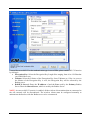
1
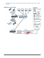
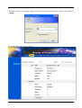
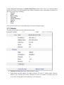
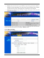
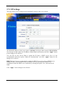
I-Fly Wireless Access Point User’s Manual (V1.0) i COPYRIGHT The Atlantis Land logo is a registered trademark of Atlantis Land SpA. All other names mentioned mat be trademarks or registered trademarks of their respective owners. Subject to change without notice. No liability for technical errors and/or omissions. Copyright 2002 by this company. DISCLAIMER This company makes no representations or warranties, either expressed or implied, with respect to the contents hereof and specifically disclaims any warranties, merchantability or fitness for any particular purpose. Any software described in this manual is sold or licensed "as is". Should the programs prove defective following their purchase, the buyer (and not this company, its distributor, or its dealer) assumes the entire cost of all necessary servicing, repair, and any incidental or consequential damages resulting from any defect in the software. Further, this company reserves the right to revise this publication and to make changes from time to time in the contents hereof without obligation to notify any person of such revision or changes. FCC Warning This equipment has been tested and found to comply with the regulations for a Class B digital device, pursuant to Part 15 of the FCC Rules. These limits are designed to provide reasonable protection against harmful interference when the equipment is operated in a commercial environment. This equipment generates, uses, and can radiate radio frequency energy and, if not installed and used in accordance with this user’s guide, may cause harmful interference to radio communications. Operation of this equipment in a residential area is likely to cause harmful interference, in which case the user will be required to correct the interference at his own expense. CE Mark Warning This is a Class B product. In a domestic environment, this product may cause radio interference, in which case the user may be required to take adequate measures. Important Note This equipment complies with FCC radiation exposure limits set forth for an uncontrolled environment. The antenna(s) used for this equipment must be installed to provide a separation distance of at least 30 cm from all persons. This equipment must not be operated in conjunction with any other antenna. INDEX CHAPITER 1 ............................................................................................................. 1 1.1 AN OVERVIEW OF THE I-FLY WIRELESS ACCESS POINT ................................................................. 1 1.2 PACKAGE CONTENTS ...................................................................................................................... 1 1.3 I-FLY WIRELESS ACCESS POINT FEATURES .................................................................................... 2 1.4 SYSTEM REQUIREMENTS ................................................................................................................. 2 1.5 I-FLY WIRELESS ACCESS POINT APPLICATION ............................................................................... 2 CHAPITER 2 ............................................................................................................. 4 2.1 CAUTIONS FOR USING THE I-FLY WIRELESS ACCESS POINT ............................................................ 4 2.2 THE FRONT LEDS ........................................................................................................................... 4 2.3 THE REAR PORTS ............................................................................................................................ 4 2.4 CABLING ......................................................................................................................................... 5 CHAPITER 3 ............................................................................................................. 6 3.1 BEFORE CONFIGURATION ............................................................................................................... 6 3.2 CONNECTING THE I-FLY WIRELESS ACCESS POINT......................................................................... 6 3.3 TEST TCP/IP................................................................................................................................... 7 3.4 CONFIGURING INTERNET EXPLORER ............................................................................................... 7 3.5 FACTORY DEFAULT SETTINGS ........................................................................................................ 8 3.5.1 LAN and WAN Port Addresses ............................................................................................... 8 3.6 RESET ............................................................................................................................................. 8 3.7 CONFIGURATION THROUGH WEB BROWSER ................................................................................... 8 3.7.1 Status..................................................................................................................................... 10 3.7.2 Basic Setting.......................................................................................................................... 11 3.7.3 IP Settings ............................................................................................................................. 13 3.7.4 Advanced Setting................................................................................................................... 14 3.7.4.1 Mode Settings ................................................................................................................ 14 3.7.4.2 Wireless Advanced Settings .......................................................................................... 17 3.7.5 Security ................................................................................................................................. 18 3.7.5.1 Password ........................................................................................................................ 18 3.7.5.2 Mac Filter....................................................................................................................... 18 3.7.6 802.1x.................................................................................................................................... 19 3.7.7 Tools...................................................................................................................................... 20 3.7.7.1 (Save/Load)Settings....................................................................................................... 21 3.7.7.2 Firmware ........................................................................................................................ 21 3.8 CONFIGURATION THROUGH AP UTILITY (OPTIONAL)............................................................. 22 3.8.1 Link Information ................................................................................................................... 22 3.8.2 AP Settings ............................................................................................................................ 24 3.8.2.1 Advanced Settings ......................................................................................................... 25 3.8.3 IP Settings ............................................................................................................................. 26 3.8.4 Security ................................................................................................................................. 27 3.8.5 802.1X Settings ..................................................................................................................... 28 APPENDIX A .......................................................................................................... 30 SUPER G.............................................................................................................................................. 30 APPENDIX B ........................................................................................................... 32 TECHNICAL FEATURES ........................................................................................................................ 32 APPENDIX C .......................................................................................................... 34 GLOSSARY .......................................................................................................................................... 34 APPENDIX D .......................................................................................................... 38 SUPPORT ............................................................................................................................................. 38 A02-WAP-54G/M2 (February 2004) Chapiter 1 Introduction And' besides available on CDRom a Quick Start Guide for a fast configuration. 1.1 An Overview of the I-Fly Wireless Access Point The device for a total freedom of movement without losing the connection. Easy to be installed and fast and flexible, with I-Fly Wireless Access Point there is no more obligation for a fixed working place: you can easily work or navigate for fun from your own garden or in different rooms of your office, always in wireless connection. The Roaming function gives you a complete freedom of movement and two or more Wireless AP can serve wireless also large headquarters. A pair of APs operating under Bridge mode to act as the bridge that connect two Ethernet networks or Ethernet enabled clients together. Repeat Mode is able to extend the effective range and coverage of the wireless network. Thanks to advanced security functions which are integrated and thanks to the troughput of the protocol IEE802.11G you are going to have a fast and flexible wireless net, hacker safe. The chipsets fully support Wi-Fi Protected Access (WPA) and the IEEE 802.11i draft security standards in hardware and high-speed encryption engines for both the Temporal Key Integrity Protocol (TKIP) and the Advanced Encryption Standard (AES) with no performance degradation. Last, but not least, this product implements Atheros Super G™ (available for devices with chipset Atheros) capabilities to deliver 108 Mbps raw data rates and 90 Mbps TCP/IP throughput for 802.11g wireless LANs (Real-time hardware data compression, Dynamic transmit and modulation optimization and Standards-compliant bursting mode adapts to the network). Integrated DHCP services, client and server, allows up to 253 users to get their IP addresses automatically on boot up from the product. Simply set local machines as a DHCP client to accept a dynamically assigned IP address from DHCP server and reboot. Each time a local machine is powered up; the AP will recognize it and assign an IP address to instantly connect it to the LAN. 1.2 Package Contents • One I-Fly Wireless Access Point • One CD-ROM containing the online manual • One Quick Start Guide • One CAT-5 LAN cable • One AC-DC power adapter (5V DC, 2A) • Warranty If any of the above items are missing, please contact your reseller. 1 1.3 I-Fly Wireless Access Point Features I-Fly Wireless Access Point provides the following features: • • • • • • • • • • Interoperable with IEEE802.11g and IEEE802.11b Atheros Super G™ capabilities to deliver 108 Mbps raw data rates and 90 Mbps TCP/IP throughput for 802.11g wireless LANs (Real-time hardware data compression, Dynamic transmit and modulation optimization and Standards-compliant bursting mode adapts to the network) WPA (with PSK, TKIP): The chipsets fully support Wi-Fi Protected Access (WPA) and the IEEE 802.11i draft security standards in hardware and high-speed encryption engines for both the Temporal Key Integrity Protocol (TKIP) and the Advanced Encryption Standard (AES) with no performance degradation. 1 Fast Ethernet port: Support automatic switching between MDI and MDI-X for 10Base-T and 100Base-TX ports is supported. An Ethernet straight or cross-over cable can be used directly, this fast Ethernet switch will detect it automatically. External Antenna: Dipole External removable Antenna (SMA) Quick Installation Wizard: Supports a WEB GUI page to install this device quickly. With this wizard, an end user can enter the information easily which they from the ISP, then surf the Internet immediately. MAC Filtering: MAC Filter function controls the MAC of the network devices that are listed in this table for access authorization or denial. Dynamic Host Control Protocol (DHCP) client and server: In the WAN site, the DHCP client can get an IP address from the Internet Server Provider (ISP) automatically. In the LAN site, the DHCP server can allocate up to 253 client IP addresses and distribute them including IP address, subnet mask as well as DNS IP address to local computers. It provides an easy way to manage the local IP network. Web based GUI: supports web based GUI for configuration and management. It is userfriendly with an on-line help, providing necessary information and assist user timing. It also supports remote management capability for remote users to configure and manage this product. Firmware Upgradeable: the device can be upgraded to the latest firmware through the WEB based GUI. 1.4 System Requirements ● ● ● ● Microsoft Internet Explorer 5.5 or higher DSL/ Cable Modem Broadband Internet connection and ISP account PCs equipped with 10Mbps or 10/100 Mbps Ethernet connection to support TCP/IP protocol One CD-ROM drive 1.5 I-Fly Wireless Access Point Application ● ● ● ● ● ● ● ● Home SOHO networking for device sharing and wireless multimedia Wireless office provides a wider range for home and SOHO Ethernet Enables wireless building-to-building data communication Built-in infrastructure mode AP provides ideal solution for: Difficult-to-wire environments Temporary LANs for scenarios such as trade-exhibitions and meetings Enables LAN adaptability to frequently changing environments ● Enables remote access to corporate network information, for example e-mail and the company home page 3 Chapiter 2 Using I-Fly Wireless Access Point 2.1 Cautions for using the I-Fly Wireless Access Point Do not place the AP under high humidity and high temperature. Do not use the same power source for AP with other equipment. Do not open or repair the case yourself. If the AP is too hot, turn off the power immediately and have a qualified serviceman repair it. Place the AP on a stable surface. Only use the power adapter that comes with the package, Using a power supply with a different voltage rating than the one included will cause damage and void the warranty for this product. 2.2 The Front LEDs LED 1 POWER 2 LAN 3 WLAN MEANING ON=Indicates proper connection to power supply. OFF= The unit is not receiving power ON= Indicates connection is established. BLINKING= Data transmissions OFF= No LAN connections ON= Link is established BLINKING= Packet transmit or receive activity OFF= No Link activity 2.3 The Rear Ports PORT 4 MEANING 1 POWER (Jack) Receptor for the Power Adapter 2 LAN 3 RESET Auto MDI/MDIX LAN ports automatically sense the cable type when connecting to Ethernet-enabled computers. After the device has turned on, press it (10s) to reset the device or restore to factory default settings. 2.4 Cabling The most common problem is bad cabling. Make sure that all connected devices are turned on. On the front of the product is a bank of LEDs. As a first check, verify that the LAN/WLAN(if connected) Link and Power line LEDs are lit. 5 Chapiter 3 Configuration The I-Fly Wireless Access Point can be configured with your Web browser. The web browser is included as a standard application in the following operation systems, UNIX, Linux, Mac OS, Windows 95/98/NT/2000/Me/XP, and etc. The product provides a very easy and user-friendly interface for configuration. With 3.1 Before Configuration This section describes the configuration required by LAN-attached PCs that communicate with the I-Fly Wireless Access Point, either to configure the device or for network access. These PCs must have an Ethernet interface installed properly, be connected to the AP either directly or through an external repeater hub, and have TCP/IP installed and configured to obtain an IP address through a DHCP server or a fixed IP address that must be in the same subnet of the AP. The default IP address of the ADSL Firewall AP is 192.168.1.1 and subnet mask is 255.255.255.0. The best and easy way is to configure the PC to get an IP address from the AP. Also make sure you have UNINSTALLED any kind of software firewall that can cause problems while accessing the 192.168.1.1 IP address of the AP. Please follow the steps below for PC’s network environment installation. First of all, please check your PC’s network components. The TCP/IP protocol stack and Ethernet network adapter must be installed. Any TCP/IP capable workstation can be used to communicate with or through the AP. To configure other types of workstations, please consult the manufacturer’s documentation. 3.2 Connecting the I-Fly Wireless Access Point • • • • Power on the device Make sure the PWR(green) Leds are OK & LAN (or WLAN) Led is lit Connect PC directly to the AP by cable or Wireless Before taking the next step, make sure you have uninstalled any software firewall 3.3 Test TCP/IP After configuring the TCP/IP protocol, you can use the ping command to check if your computer has successfully connected to this AP. The following example shows the ping procedure for Windows 98 . First, execute the ping command. Ping 192.168.1.1 If the following messages appear: Pinging 192.168.1.1 with 32 bytes of data: Reply from 192.168.1.1: bytes=32 times<10ms TTL=64 Reply from 192.168.1.1: bytes=32 times<10ms TTL=64 Reply from 192.168.1.1: bytes=32 times<10ms TTL=64 A communication link between your computer and this AP has been successfully established. Otherwise, if you get the following messages, Pinging 192.168.1.1 with 32 bytes of data: Request timed out. Request timed out. Request timed out. There must be something wrong in configuring procedure or cable issue. Please check the LAN/WLAN LINK LED must be lighted. Or check TCP/IP configuration of your computer. Try to press the key reset for 10 seconds and release it. The AP should effect a reboot. 3.4 Configuring Internet Explorer Click Tools on the main menu bar, then click Internet Options. The next screen to appear has several tabs across the top. Select the Connection tab. Chose Never Dial a Connection or Dial whenever a network connection is not present 7 3.5 Factory Default Settings Before configurating this AP, you need to know the following default settings. Web Configurator Username : admin Password: admin Device IP Network settings in LAN site IP Address : 192.168.1.1 Subnet Mask : 255.255.255.0 DHCP server : DHCP server disable Wireless Channel=6 WEP/WAP=disable 3.5.1 LAN and WAN Port Addresses The parameters of LAN and WAN ports are pre-set in the factory. The default values are shown below. LAN Port IP address 192.168.1.1 Subnet Mask DHCP server 255.255.255.0 Disable 3.6 Reset The default username and password are admin and admin respectively. If you ever forget the password to log in, you may press the RESET button (for 12s) to restore the factory default settings(sez 3.5). 3.7 Configuration through Web Browser Open the web browser, enter the local port IP address of this AP, which defaults at http://192.168.1.1, and click “Go”, The below window will popup. Please enter the user name and password. Both of the default is “admin”. Now, the main menu screen is popup. 9 At the configuration homepage (if Quick Setup Wizard starts, please close it or read the printed Quick Start Guide), the left navigation page where bookmarks are provided links you directly to the desired setup page, including: • Wizard • Status • Basic Setting • IP Setting • Advanced Setting • Security • 802.1x • Tools Click on the desired item to expand the page in the main navigation page. 3.7.1 Status This page as below shows you the following information. • • Firmware Version: Shows the current firmware version. LAN: Shows the Mac address, IP address (default: 192.168.1.1), Subnet Mask, Gateway Address. The current LAN traffic calculated in terms of number of packets sent and received by AP through wired connection is also displayed. • • Wireless: Shows the Mac address, current ESSID, the status of Encryption Function (Enable or Disable), the current using channel. The current wireless traffic calculated in terms of number of packets sent and received by AP through wireless communication is also displayed. View Log: Upon clicked, the page will change to log page. The log page records every event and the time that it happens. You may clear the entries recorded in the log by clicking the “Clear Log” button, and refresh the screen to show the latest log entries by clicking the “Refresh” button. 3.7.2 Basic Setting This is the page allow you to change the access point. 11 • • • • • • • • AP Name: The name of the AP, which can be used to identify the Access Point among the all the Access Points in the wireless network. SSID: Service Set Identifier, which is a unique name shared among all clients and nodes in a wireless network. The SSID must be identical for each clients and nodes in the wireless network. Channel: The channel that AP will operate in. You can select the channel range of 1 to 11 for North America (FCC) domain, 1 to 13 for European (ETSI) domain and 1 to 14 for Japanese domain. Authentication Type: The authentication type default is set to open system. There are four options: open system; shared key; WPA; WPA-PKS. You may want to set to Shared Key when the clients and AP in the same wireless network enable the WEP encryption. All the nodes and hosts on the network must use the same authentication type. WEP Key: To disable WEP security, click on the “Disable” option. To enable WEPsecurity, there are 2 types to select – 64bits and 128 bits. When it is selected, the key value must be entered in ASCII or HEX format. NOTE: When WEP security is enabled, all the wireless clients that wish to connect to the Access Point must also have WEP enabled with the identical WEP Key value entered. WPA: WPA is available in authentication mode as the below screen. It is required to set 802.1X setting first before you use WPA. WPA-PSK (Pre Shared Key mode): WPA is available in authentication mode as the below screen. It is required to set 802.1X setting first before you use WPA. If WPA-PSK is enabled, users need to set the key in the passphrase field as the below screen. The key length should be 8 characters at least. Apply: For the changes made to any of the items above to be effective, click “Apply”. The new settings are now been saved to Access Point and will be effective once the Access Point restarts. 3.7.3 IP Settings This page allows you to configure the IP and DHCP settings of the Access Point. The default IP address of this access point is 192.168.1.1 with the subnet mask of 255.255.255.0. You can type in other values for IP Address, Subnet Mask and Gateway and click “Apply” button for the changes to be effective. You can also set the Access Point to obtain the IP from a DHCP server, but it is not recommended. Select the option “Obtain IP Automatically” and click “Apply” button for the changes to be effective. DHCP Server: It is not recommended to enable the DHCP Server if you have a DHCP server running in your LAN network because it probably will cause possible the conflict of IP assignment. Enable the DHCP server function by selecting the option “On”, and enter the IP range. Click “Apply” for the changes to be effective. 13 3.7.4 Advanced Setting This page contains configurations for advanced users, which the change reflects the wireless performance and operating modes. 3.7.4.1 Mode Settings Select one of the AP operating modes for different application of Access Point. 1 AP: The normal Access Point operating mode which forms a wireless ESS network with its wireless clients. In figure an example of configuration. 2 AP Client: Acts as an Ethernet-to-Wireless Bridge, which allows a LAN or a single computer station (no driver installation is need) to join a wireless ESS network through it. You must make sure SSID and Channel is set the same as that AP you wish to connect. Remote AP SSID: key in the LAN Mac address (NOT wireless Mac address) of the AP that you wish to get connected. Please note that if you leave Mac address as 000000000000, then you will get connected by the SSID that is set in you AP. In figure an example of configuration. 15 3 Wireless Bridge: A pair of APs operating under Bridge mode to act as the bridge that connect two Ethernet networks or Ethernet enabled clients together. You must make sure that the SSID and Channel is set the same as that AP you wish to connect. Remote Bridge MAC filed: key in the LAN Mac address (NOT wireless Mac address) of the AP that you wish to get connected. 4 Multiple Bridge: A group of APs which consists of two or more APs operating under Multiple Bridge mode, that can connect two or more Ethernet networks or Ethernet enabled clients together. All APs have to use the same Channel and SSID in order to set a Multiple Bridge network. 5 Repeat Mode: It is able to extend the effective range and coverage of the wireless network. Please make sure the SSID is the same as that AP you want to extend. Wireless LAN is Half Duplex, so one transaction pass-through 2 wireless its real data-rate will be half of normal one. 3.7.4.2 Wireless Advanced Settings This screen enables you to configure advanced wireless functions. • • • • • • • • Beacon Interval: Type the beacon interval in the text box. You can specify a value from 1 to 1000. The default beacon interval is 100. RTS Threshold: Type the RTS (Request-To-Send) threshold in the text box. This value stabilizes data flow. If data flow is irregular, choose values between 256 and 2432 until data flow is normalized. Fragmentation Threshold: Type the fragmentation threshold in the text box. If packet transfer error rates are high, choose values between 256 and 2432 until packet transfer rates are minimized. (Note:set this fragmentation threshold value may diminish system performance.) DTIM Interval: Type a DTIM (Delivery Traffic Indication Message) interval in the text box. You can specify a value between 1 and 65535. The default value is 3. SSID Broadcast: While SSID Broadcast is enabled, all wireless clients will be able to communicate with the access point. For secure purpose, you may want to disable SSID broadcast to allow only those wireless clients with the AP SSID to communicate with the AP. TX Rates (MBps): Select one of the wireless communications transfer rates, measured in megabytes per second, based upon the speed of wireless adapters connected to the WLAN. 11g only mode: enable or disable. SuperG: Enable SuperG for superior performance. Super G mode is disabled by selecting “Disable” from the drop list. If you like to use Super G to enhance the speed, there are three options on Super G mode: Super G without turbo; Super G with Dynamic turbo and Super G with Static turbo. Turbo mode indicates the combination of two channels to enhance the throughput. Super G without turbo indicates that it is on Super G mode without the channel’s combination. Dynamic turbo is able to automatically detect if any 17 • ‘SuperG based’ product is available. If no, the connection is via ‘normal’ G. Static turbo means it will not go back to ‘normal’ G once it starts Antenna Power Transmit: Select the Antenna Power transmit for wireless interface. 3.7.5 Security This page is where you configure the security features supported by this Access Point. 3.7.5.1 Password This screen enables you to set administrative and user passwords. These passwords are used to gain access to the AP interface. Password: Allow you to change the new login password. Here are the necessary steps: 1. Enter the new password in the “AP Password New:” field. 2. Enter the new password again in the “Confirm” field. 3. Click “Apply” 3.7.5.2 Mac Filter This page enables you to define access restrictions. MAC Filter: MAC Filter function controls the MAC of the network devices that are listed in this table for access authorization or denial. When MAC Filter is enabled, by selecting the “Enabled” radio box, select one of two choices: Only deny PCs with MAC listed below to access device Only allow PCs with MAC listed below to access device The maximum number of MAC addresses that can be stored is 50. You can browse through the MAC address saved by selecting the drop-down box. For any changes made in the security page, click “Apply” for the changes to be active. 3.7.6 802.1x There are three essential components to the 802.1x infrastructure: (1) Supplicant, (2) Authenticator and (3) Server. The Access Point serves as an Authenticator, and the EAP methods used must be supported by the backend Radius Server. The 802.1x security supports MD5 and TLS Extensive Authentication Protocol (EAP). Please follow the steps below to configure 802.1x security. 19 • • • Enable 802.1x security by selecting “Enable”. If MD5 EAP method is used then you can skip step 2 and go to step 3. Select the Encryption Key Length Size ranging from 64 to 128 Bits that you would like to use. Select the Lifetime of the Encryption Key from 5 Minutes to 1 Day. As soon as the lifetime of the Encryption Key is over, the Encryption Key will be renewed by the Radius server. • Enter the IP address, the Port and the Shared Secret used by the Primary Radius Server. • Enter the IP address, the Port and the Shared Secret used by the Secondary Radius Server. • Click “Apply” button for the 802.1x settings to take effect after Access Point reboots itself. NOTE: As soon as 802.1x security is enabled, all the wireless client stations that are connect to the Access Point currently will be disconnected. The wireless clients must be configured manually to authenticate themselves with the Radius server to be reconnected. 3.7.7 Tools This page enables you to: • Backup • Restore • Restore Default Settings • Firmware Upgrade 3.7.7.1 (Save/Load)Settings • Backup Settings: Click on “Backup” button, which will open a FileSave Dialog box, where you get to save all the current settings and configurations to a file. • Restore Settings: Click on the “Browse” button to open a FileOpen Dialog box, where you get to select the file, which you save previous settings and configurations. Upon selecting the saved file, click “Restore” and complete the restore process when the access point re-operates after it restarts. • Restore to default settings: Click on “Default” button to restore the access point 3.7.7.2 Firmware This screen enables you to keep the AP firmware (Do NOT upgrade firmware over a wireless connection. Failure of the device may result. Use only hard-wired network connections) up to date. Please follow the below instructions: • Download the latest firmware from www.atlantis-land.com Web site, and save it to your disk. • Click Browse and go to the location of the downloaded firmware file. Select the file and click Upgrade to update the firmware to the latest release 21 3.8 Configuration through AP Utility (Optional) Launch Setup.exe (CDRom:\Utility\setup.exe) to install tha AP Utility. 3.8.1 Link Information Link information is showing you the related current setting of the first. 23 3.8.2 AP Settings Basic Setting: • ESSID: It is used by all wireless devices within the wireless network. • Channel: Select the appropriate channel from the dropping list. All wireless devices with the same ESSID will automatically use this channel to communicate with this access point. • AP Name: users can set the name for access point so as to easily manage the access points while there are several access points in the network.. Mode Setting: • Access Point:This is the default for this access point. It connects the wireless PCs to wired network. • Access Point Client:Acts as an Ethernet-to-Wireless Bridge, which allows a LAN or a single computer station to join a wireless ESS network through it. You must make sure SSID and Channel is set the same as that AP you wish to connect. • Wireless Bridge:A pair of APs operating under Bridge mode to act as the bridge that connect two Ethernet networks or Ethernet enabled clients together. You must make sure that the SSID and Channel is set the same as that AP you wish to connect. • Multiple Bridge:A group of APs that consists of two or more APs operating under Multiple Bridge mode, that can connect two or more Ethernet networks or Ethernet enabled clients together. • Repeat Mode:It is able to extend the effective range and coverage of the wireless network. Please make sure the SSID is the same as that AP you want to extend. 3.8.2.1 Advanced Settings • • • • • • • • SSID Broadcast: While SSID Broadcast is enabled, all wireless clients will be able to communicate with the access point. For secure purpose, you may want to disable SSID broadcast to allow only those wireless clients with the AP SSID to communicate with the access point. Beacon Interval: To set the period of time in milliseconds that AP sends out a beacon. Default is 100 milliseconds. RTS Threshold: To set the size of RTS/CTS packet size. Default is 2432 bytes. Fragmentation Threshold: To set the number of bytes used for the fragmentation boundary for directed messages. Default is 2436 bytes. DTIM Interval: This value indicates the interval of the Delivery Traffic Indication Message (DTIM). A DTIM field is a countdown field informing clients of the next window for listening to broadcast and multicast messages. When the access point has buffered broadcast or multicast messages for associated clients, it sends the next DTIM with a DTIM interval value. Access point clients hear the beacons and awaken to receive the broadcast and multicast messages. TX Rates (MBps): Select one of the wireless communications transfer rates, measured in megabytes per second, based upon the speed of wireless adapters connected to the WLAN. 11G Only Mode: enable or disable. Super G: Super G mode is disabled by selecting “Disable” from the drop list. If you like to use Super G to enhance the speed, there are three options on Super G mode: Super G without turbo; Super G with Dynamic turbo and Super G with Static turbo. Turbo mode 25 indicates the combination of two channels to enhance the throughput. Super G without turbo indicates that it is on Super G mode without the channel’s combination. Dynamic turbo is able to automatically detect if any ‘SuperG based’ product is available. If no, the connection is via ‘normal’ G.. Static turbo means it will not go back to ‘normal’ G once it starts. 3.8.3 IP Settings • • • Fixed IP Address: Users can assign a fixed IP address to this AP manually. DHCP Server: Enable the DHCP server function by clicking the radio button if you have the DHCP server running in your LAN network. It is not recommended because it probably will cause possible the conflict of IP assignment. DHCP Client: You can also set the Access Point to obtain the IP from a DHCP server, but it is not recommended. Select the option “DHCP Client” and click “Apply” button for the changes to be effective. 3.8.4 Security • • Data Encryption: please tick it if you like to have WEP key as the encryption mechanism. Authentication Mode: The authentication type default is set to open system. There are four options: open system; shared key; WPA; WPA-PKS. You may want to set to Shared Key when the clients and AP in the same wireless network enable the WEP encryption. All the nodes and hosts on the network must use the same authentication type. • WEP Key: To disable WEP security, click on the “Disable” option. To enable WEPsecurity, there are 2 types to select – 64bits and 128 bits. When it is selected, the key value must be entered in ASCII or HEX format. There are four key sets are available to assign. NOTE: When WEP security is enabled, all the wireless clients that wish to connect to the Access Point must also have WEP enabled with the identical WEP Key value entered. • WPA: WPA is available in authentication mode as the below screen. It is required to set 802.1X setting first before you use WPA. • WPA-PSK (Pre Shared Key mode): WPA is available in authentication mode as the below screen. It is required to set 802.1X setting first before you use WPA. If WPA-PSK is enabled, users need to set the key in the passphrase field as the below screen. The key length should be 8 characters at least. 27 3.8.5 802.1X Settings There are three essential components to the 802.1x infrastructure: (1) Supplicant, (2) Authenticator and (3) Server. The Access Point serves as an Authenticator, and the EAP methods used must be supported by the backend Radius Server. The 802.1x security supports MD5 and TLS Extensive Authentication Protocol (EAP). Please follow the steps below to configure 802.1x security. If users like to set 802.1X or the authentication type is set to WPA, please enable 802.1X function by ticking it. • Encryption Key: Select the Encryption Key Length Size ranging from 64 to 128 Bits that you would like to use. • Lifetime: Select the Lifetime of the Encryption Key from 5 Minutes to 1 Day. As soon as the lifetime of the Encryption Key is over, the Encryption Key will be renewed by the Radius server. • RADIUS Server1: Enter the IP address of and the Port used by the Primary Radius Server Enter the Shared Secret, which is used by the Radius Server. NOTE: As soon as 802.1X security is enabled, all the wireless client stations that are connected to the AP currently will be disconnected. The wireless clients must be configured manually to authenticate themselves with the Radius server to be reconnected. 29 APPENDIX A Super G SuperG™ is an assemble of solutions that are Atheros® properties .They allow you to obtain performances far superior to the IEEE802.11g standard . Performance Atheros® chip which has been purposely developed for the property technology of SuperG™, reaches a performance boost never seen before , reaching results that are even doubled contrasted with the ones from IEEE802.11g devices . Security The integration of an all-hardware engine which allows the use of the best Wi-Fi protected access (WPA) avoiding any loss of performance is an highly relevant characteristic . Technologies and Performances: • Packet Bursting. It is a particular technique of transmission that aims to enlarge the throughput reducing the usual overhead of the wireless transmissions. Every transmission is divided from the following one by a period called Distributed Interframe Space (DIFS). After this weft all the devices contend for the access. On the contrary when you use the Packet Bursting technique you can have more transmissions taking place in a unique sequence. • Fast Frames (dynamic transmit optimisations). This technique aims to enlarge the throughput increasing the number of bits sent by frame and reducing the frame time itself. Both the algoritmi for the contest and the frame structure itself have been improved in order to increase the performances. This means that in every 802.11 frame they put no longer a single Ethernet package of 1500 byte, instead the frame structure results from a range of elaborations aiming to obtain optimum condition for the transmission speed. • Data Compression. In the chip there is implemented an engine that uses a compression algoritmo of the Lempel Ziv kind (similar to the Winzip one ). Any kind of transmission is first compress , then transmitted and at last decompress by the receiver , in a totally clear way for the user. It’s clear that , depending on the data sent , the earnings will be limited or relevant • Turbo Mode .The range provided by different channels is being unified in order to double the data rate. The Turbo Mode integrates the possibility to go back to a traditional use of the channels in order to permit to the IEEE802.11g devices to operate correctly.With the Turbo Mode the only channel used is number 6. The AD-Hoc mode is not supported with the Turbo one. 30 Maximum theoretical limits* Standard Channel Modulation Max LinkRate 11Mbps 54Mbps Max Throughput(TCP) 5.9 Mbps 14.4 Mbps Max Throughput(UDP) 7.1 Mbps 19.5 Mbps 3 CCK 802.11b CCK/OFDM 802.11b and 3 802.11g CCK/OFDM 54Mbps 24.4 Mbps 30.5 Mbps 802.11g only 3 1 OFDM 108Mbps 42.9 Mbps 54.8 Mbps SuperG * In this table the achievable theoretical limits are shown in the following conditions : 1500 bytes per package, encryption empowered, no transmission errors, maximum range available for the channel, default configuration per 802.11 MAC 31 APPENDIX B Technical Features Physical Interfaces LAN: 1 RJ45 10/100 Base-TX Fast Ethernet Wireless 54Mbps (IEEE802.11g) and 11Mbps (IEEE802.11b) 3 Led for easy diagnostic Reset Wireless Interface Chipset Atheros™ Dipole External removable (reverse SMA) Antenna Radio Spec. Standard IEEE802.11g and IEEE802.11b DSSS(Direct Sequence Spread Spectrum) Modulation: QPSK / BPSK / CCK and OFDM RF Frequency:2.400 GHz ~2.4835GHz Operating Channel:: 13 (Europe) Data Rate (with automatic adaptation): 802.11g: Up to 54Mbps (with Automatic Fall-Back) and 108Mbps in SuperG™ Coverage Area: [Outdoor <100M ; Indoor <30M] Advanced Characteristics Atheros Super G™ capabilities to deliver 108 Mbps raw data rates and 90 Mbps TCP/IP throughput for 802.11g wireless LANs (Real-time hardware data compression, Dynamic transmit and modulation optimization and Standards-compliant bursting mode adapts to the network) The chipsets fully support Wi-Fi Protected Access (WPA) and the IEEE 802.11i draft security standards in hardware and high-speed encryption engines for both the Temporal Key Integrity Protocol (TKIP) and the Advanced Encryption Standard (AES) with no performance degradation. Security Wi-Fi Protected Access (without performance degradation) and WEP 64/128 802.1x security (MD5 and TLS) Port-Isolation (TBD) MAC Filtering SSID Broadcast Disable function Advanced Features Supports DHCP Server/Client Access Point Access Point Client Wireless Wireless Bridge and Multiple Bridge Repeat Mode Configuration & Management Web-based configuration utility PC Utility supporting Windows98SE/ME/2000/XP TFTP for software upgrade available Status log Physical and Environmental Power Consumation: (5V ± 5%, 2.4A AC Adapter) Dimensions: 145mm*110mm*35mm Weight: 350g Temperature: Operating:[0°C to 49°C], Storage:[-20°C to 65°C] Humidity: 5-95% (without condensing) Package contents I-Fly Wireless Access Point CD-ROM containing drivers and the online manual (English and Italian) Quick start guide ((English, Italian, French, Spanish and German) AC-DC power adapter CAT-5 LAN cable 33 APPENDIX C Glossary Access Point An interview networking device that seamlessly connects wired and wireless networks Authentication Authentication refers to the verification of a transmitted message’s integrity. DMZ DMZ (DeMilitarized Zone) is a part of a network that is located between a secure LAN and an insecure WAN. DMZs provide a way for some clients to have unrestricted access to the Internet. DHCP DHCP (Dynamic Host Configuration Protocol) software automatically assigns IP addresses to client stations logging onto a TCP/IP network, which eliminates the need to manually assign permanent IP addresses. DNS DNS stands for Domain Name System. DNS converts machine names to the IP addresses that all machines on the net have. It translates from name to address and from address to name. Domain Name The domain name typically refers to an Internet site address. DTIM DTIM (Delivery Traffic Indication Message) provides client stations with information on the next opportunity to monitor for broadcast or multicast messages. Filter Filters are schemes which only allow specified data to be transmitted. For example, the AP can filter specific IP addresses so that users cannot connect to those addresses. Firewall Firewalls are methods used to keep networks secure from malicious intruders and unauthorized access. Firewalls use filters to prevent unwanted packets from being transmitted. Firewalls are typically used to provide secure access to the Internet while keeping an organization's public Web server separate from the internal LAN. Firmware Firmware refers to memory chips that retain their content without electrical power (for example, BIOS ROM). The AP firmware stores settings made in the interface. Fragmentation Refers to the breaking up of data packets during transmission. FTP FTP (File Transfer Protocol) is used to transfer files over a TCP/IP network, and is typically used for transferring large files or uploading the HTML pages for a Web site to the Web server. Gateway Gateways are computers that convert protocols enabling different networks, applications, and operating systems to exchange information. Host Name The name given to a computer or client station that acts as a source for information on the network. HTTP HTTP (HyperText Transport Protocol) is the communications protocol used to connect to servers on the World Wide Web. HTTP establishes a connection with a Web server and transmits HTML pages to client browser (for example Windows IE). HTTP addresses all begin with the prefix 'http://' prefix (for example, http://www.yahoo.com). ICMP ICMP (Internet Control Message Protocol) is a TCP/IP protocol used to send error and control messages over the LAN (for example, it is used by the AP to notify a message sender that the destination node is not available). IP IP (Internet Protocol) is the protocol in the TCP/IP communications protocol suite that contains a network address and allows messages to be routed to a different network or subnet. However, IP does not ensure delivery of a complete message—TCP provides the function of ensuring delivery. IP Address The IP (Internet Protocol) address refers to the address of a computer attached to a TCP/IP network. Every client and server station must have a unique IP address. Clients are assigned either a permanent address or have one dynamically assigned to them via DHCP. IP addresses are written as four sets of numbers separated by periods (for example, 211.23.181.189). ISP An ISP is an organization providing Internet access service via modems, ISDN (Integrated Services Digital Network), and private lines. LAN LANs (Local Area Networks) are networks that serve users within specific geographical areas, such as in a company building. LANs are comprised of servers, workstations, a network operating system, and communications links such as the AP. MAC Address A MAC address is a unique serial number burned into hardware adapters, giving the adapter a unique identification. Metric A number that indicates how long a packet takes to get to its destination. 35 MTU MTU (Maximum Transmission/Transfer Unit) is the largest packet size that can be sent over a network. Messages larger than the MTU are divided into smaller packets. NAT NAT (Network Address Translation - also known as IP masquerading) enables an organization to present itself to the Internet with one address. NAT converts the address of each LAN node into one IP address for the Internet (and vice versa). NAT also provides a certain amount of security by acting as a firewall by keeping individual IP addresses hidden from the WAN. (Network) Administrator The network administrator is the person who manages the LAN within an organization. The administrator's job includes ensuring network security, keeping software, hardware, and firmware upto-date, and keeping track of network activity. NTP NTP (Network Time Protocol) is used to synchronize the realtime clock in a computer. Internet primary and secondary servers synchronize to Coordinated Universal Time (UTC). Packet A packet is a portion of data that is transmitted in network communications. Packets are also sometimes called frames and datagrams. Packets contain not only data, but also the destination IP address. Ping Ping (Packet INternet Groper) is a utility used to find out if a particular IP address is present online, and is usually used by networks for debugging. Port Ports are the communications pathways in and out of computers and network devices (APs and switches). Most PCs have serial and parallel ports, which are external sockets for connecting devices such as printers, modems, and mice. All network adapters use ports to connect to the LAN. Ports are typically numbered. PPPoE PPPoE (Point-to-Point Protocol Over Ethernet) is used for running PPP protocol (normally used for dial-up Internet connections) over an Ethernet. PPTP Point-to-Point Tunneling Protocol uses TCP to deal data for tunnel maintenance, and uses PPP for sum up the information carried within the tunnel. The data carried within the tunnel can be compressed or encrypted. The encryption method used is RSA RC4. PPTP can operate when the protocol is supported only on the client and the server located on the other end that the client is corresponds with. No support is essential from any of the APs or servers within the network the two PCs are connecting across. Protocol A protocol is a rule that governs the communication of data. RIP RIP (Routing Information Protocol) is a routing protocol that is integrated in the TCP/IP protocol. RIP finds a route that is based on the smallest number of hops between the source of a packet and its destination. RTS RTS (Request To Send) is a signal sent from the transmitting station to the receiving station requesting permission to transmit data. Server Servers are typically powerful and fast machines that store programs and data. The programs and data are shared by client machines (workstations) on the network. SMTP SMTP (Simple Mail Transfer Protocol) is the standard Internet e-mail protocol. SMTP is a TCP/IP protocol defining message format and includes a message transfer agent that stores and forwards mail. Subnet Mask Subnet Masks (SUBNETwork masks) are used by IP protocol to direct messages into a specified network segment (i.e., subnet). A subnet mask is stored in the client machine, server or AP and is compared with an incoming IP address to determine whether to accept or reject the packet. SysLog Server A SysLog server monitors incoming Syslog messages and decodes the messages for logging purposes. TCP (Transmission Control Protocol) is the transport protocol in TCP/IP that ensures messages over the network are transmitted accurately and completely. TCP/IP TCP/IP (Transmission Control Protocol/Internet Protocol) is the main Internet communications protocol. The TCP part ensures that data is completely sent and received at the other end. Another part of the TCP/IP protocol set is UDP, which is used to send data when accuracy and guaranteed packet delivery are not as important (for example, in real-time video and audio transmission). The IP component of TCP/IP provides data routability, meaning that data packets contain the destination station and network addresses, enabling TCP/IP messages to be sent to multiple networks within the LAN or in the WAN. UDP (User Datagram Protocol) is a protocol within TCP/IP that is used to transport information when accurate delivery isn't necessary (for example, real-time video and audio where packets can be dumped as there is no time for retransmitting the data). Virtual Servers Virtual servers are client servers (such as Web servers) that share resources with other virtual servers (i.e., it is not a dedicated server). WAN WAN (Wide Area Network) is a communications network that covers a wide geographic area such as a country (contrasted with a LAN, which covers a small area such as a company building). 37 APPENDIX D Support If you have any problems with the Wireless AP, please consult this manual. If you continue to have problems you should contact the dealer where you bought this AP. If you have any other questions you can contact the Atlantis Land company directly at the following address: AtlantisLand spa Via De Gasperi 122 20017 Mazzo di Rho(MI) Tel: 02/93906085, 02/93907634(help desk) Fax: 02/93906161 Email: [email protected] or [email protected] WWW: http://www.atlantisland.it or www.atlantis-land.com All brand and product names mentioned in this manual are trademarks and/or registered trademarks of their respective holders. 38