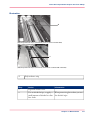
1
Océ User manual
Océ BLM500/550/550 PRO
Operating information
Copyright
© 2007-2010 Océ
All rights reserved. No part of this work may be reproduced, copied, adapted, or transmitted
in any form or by any means without written permission from Océ.
Océ makes no representation or warranties with respect to the contents hereof and specifically disclaims any implied warranties of merchantability or fitness for any particular purpose.
Further, Océ reserves the right to revise this publication and to make changes from time
to time in the content hereof without obligation to notify any person of such revision or
changes.
Edition: 2010-10
Contents
Contents
Chapter 1
Introduction to the Booklet maker....................................................................5
Introduction.................................................................................................6
Description of the Booklet maker..............................................................8
Right Hand Side of the Booklet maker...................................................10
The Rear Panel of the Booklet maker.....................................................11
The mains input panel of the Book Stacker...........................................12
Chapter 2
How to run the Booklet maker........................................................................13
Before You Begin.....................................................................................14
Turn On the Booklet maker.....................................................................15
Enter the Job Settings.............................................................................16
Stacker and Book Stacker adjustment....................................................19
Run the job................................................................................................20
Chapter 3
The User Interface.............................................................................................21
The Touch Screen....................................................................................22
The Job Mimic..........................................................................................25
The BASIC Window..................................................................................27
The LOAD & SAVE Window....................................................................29
The ADVANCED Window........................................................................31
The CONFIGURE Window.......................................................................32
The MENU Window.................................................................................33
Chapter 4
Standard Tasks.................................................................................................35
Load and Save the Job Settings.............................................................36
Adjust the Stitch Pitch..............................................................................37
Open the Connecting Bridge Cover........................................................38
Open and Close the Folder Cover...........................................................39
Lift and Lower the Clincher Frame..........................................................41
Open the Gathering Area Cover..............................................................43
Lift the Booklet maker Main Deck...........................................................44
Empty the Trim Bin..................................................................................46
Open the Stitch-Wire Cabinet..................................................................48
Adjust the Stacker....................................................................................49
Adjust the Book Stacker...........................................................................51
Unload the Book Stacker.........................................................................52
Operate the Booklet maker offline..........................................................53
3
Contents
Chapter 5
Error Conditions, Problems and Solutions.....................................................55
Clear a Printer Error.................................................................................56
Clear a Booklet maker error.....................................................................57
General Problems.....................................................................................58
Book Quality..............................................................................................60
Error Messages.........................................................................................75
Clear Paper Jams.....................................................................................88
Clear a Stitch-wire Jam..........................................................................100
Clear a Stitch Head Jam........................................................................102
Calibrate the Touch Screen...................................................................106
Change the fuses of the Booklet maker................................................107
Change the fuses of the Book Stacker..................................................108
Manually park the Shuttle.....................................................................109
Chapter 6
Maintenance....................................................................................................111
About Maintenance................................................................................112
Booklet maker cleaning.........................................................................114
Clean the Static Elimination Bars..........................................................115
Clean the Former Roller.........................................................................118
Clean the Polyurethane Strips in the Form Clamp..............................120
Clean the Trimmings-removal Fingers.................................................123
Clean excess grease from the Stitch Head...........................................126
Lubricate the Stitch Head......................................................................128
Install New Stitch-wire...........................................................................133
Clear paper from the trim stop..............................................................138
Appendix A
Specifications..................................................................................................141
Specifications.........................................................................................142
Appendix B
Declaration of Conformity..............................................................................145
Declaration of Conformity.....................................................................146
4
Chapter 1
Introduction to the Booklet maker
Introduction
Introduction
Introduction
This User Manual is applicable to all model Océ BLM550 booklet makers. The Océ
BLM550 PRO version is an Océ BLM550 booklet maker with the optional Book
Stacker attached. The User Manual is also applicable to all model Océ BLM500 booklet
makers from serial number 120 onwards with software version 3.1. (It is possible to
retrofit the optional Book Stacker to these Océ BLM500 models).
Caution:
A CAUTION message tells you that a procedure or operation can be dangerous. To
prevent injury, you must follow the instructions.
Attention:
An ATTENTION message tells you that a procedure or operation can damage the machine
or the product. To prevent damage, you must follow the instructions.
Documentation
Your Manual
The User Manual of the Booklet maker describes how to do these tasks:
■ Operate the Booklet maker
■ Find and correct error conditions
■ Do normal maintenance tasks
Operator training is given when the Booklet maker is installed. To make sure you use
your Booklet maker correctly, read your manual.
The User Manual of the Booklet maker does not describe the operation of the printer.
If needed, refer to your printer user manual.
Safety Information
Safety information is included in the separate “Safety Information Manual”. Read the
safety information before you use your Booklet maker.
6
Chapter 1 - Introduction to the Booklet maker
Introduction
Installation
Your Booklet maker must be installed by a service engineer. Special knowledge is needed
to install the machine.
Attention:
Only connect the machine to a mains power supply of the correct voltage with a good
earth connection. The correct machine voltage is shown on the label at the mains power
supply input on the rear of the machine. If the machine is connected to the wrong supply,
the warranty is cancelled.
How to Get Help
If you have any questions or problems, refer to the problem solving section in this manual
(see chapter “Error Conditions, Problems and Solutions” ). Contact your Booklet maker
supplier for further help
Chapter 1 - Introduction to the Booklet maker
7
Description of the Booklet maker
Description of the Booklet maker
Introduction
The Booklet maker operates online with digital printers to process sets of printed pages
into stitched books. The main parts are shown below.
Illustration
A
B
C
D
[1] Operator Side of the Booklet maker
E
[2] Book Stacker (optional)
8
Chapter 1 - Introduction to the Booklet maker
Description of the Booklet maker
Component - function table
Operator Side of the Booklet maker#
Component
Function
A
The connecting
bridge
The connecting bridge moves the printed sheets from
the printer to the Booklet maker. If needed, the sheets
are rotated into the correct direction. Rotation lets the
printer operate at optimum print speed. Adjustment
for the size of the paper and sheet rotation is automatic,
according to the settings entered on the touch screen.
B
The user interface
The user interface has a colour touch screen, a start
button and a stop button .
C
The Booklet maker
The Booklet maker stitches, folds, spine-forms and
trims the sheets to make a finished book.
D
The Stacker
The Stacker collects the finished books (see ‘Illustration’
on page 8).
E
The Book Stacker
The optional Book Stacker is a high-capacity stacker
for the finished books (see ‘Illustration’ on page 8).
Chapter 1 - Introduction to the Booklet maker
9
Right Hand Side of the Booklet maker
Right Hand Side of the Booklet maker
Illustration
A
B
[3] Right hand side of the Booklet maker
Component - function table
Right hand side of the Booklet maker#
10
Component
Function
A
The stitch wire
cabinet
The stitch-wire cabinet holds the spool of stitch-wire.
B
Trim Bin
The trim bin collects the paper that is trimmed from
the edge of the book
Chapter 1 - Introduction to the Booklet maker
The Rear Panel of the Booklet maker
The Rear Panel of the Booklet maker
Illustration
A
B
C
D
E
F
[4] The Rear Panel of the Booklet maker
Component - function table
The Rear Panel of the Booklet maker#
Component
Function
A
Rating and serial label
The rating label displays the type of machine, serial
number, power use and fuse information.
B
Mains power
ON/OFF switch
The mains power ON/OFF switch turns ON or turns
OFF the Booklet maker. When you turn OFF the
Booklet maker, the current settings are stored.
C
Voltage advisory label
The voltage advisory label tells the installer to refer
to the installation instructions before the Booklet
maker is connected to mains power. The Booklet
maker can be adjusted for one of several different
input voltages.
D
Fuses
The fuses make sure the operator and the machine
are protected if there is an electrical problem or short
circuit.
E
Voltage label
The voltage label is fitted to the Booklet maker during the installation procedure. The voltage label displays the selected voltage.
F
Mains power input
connector
The mains power input connector is used to connect
the Booklet maker to mains electrical power.
Chapter 1 - Introduction to the Booklet maker
11
The mains input panel of the Book Stacker
The mains input panel of the Book Stacker
Illustration
A
B
C
D
E
[5] The mains input panel of the Book Stacker
Component - function table
The mains input panel of the Book Stacker#
12
Component
Function
A
Rating and serial label
The rating label displays the type of machine, serial
number, power use and fuse information.
B
Voltage advisory label
The voltage advisory label shows that the input
voltage is 230 V AC. The 230 V power is supplied
by the Océ BLM500/550/550 PRO.
C
Power input connector
The power input connector is used to connect the
power supply from the Océ BLM500/550/550
PRO to the Book Stacker.
D
Mains power ON/OFF
switch
The mains power ON/OFF switch turns ON the
Book Stacker or turns OFF the Book Stacker.
E
Fuses
The fuses make sure the operator and the machine
are protected if there is an electrical problem or
short circuit.
Chapter 1 - Introduction to the Booklet maker
Chapter 2
How to run the Booklet
maker
Before You Begin
This chapter gives information on how to run a job on the Booklet maker. For information on how
to operate the printer, refer to the printer documentation.
Information about the user interface is included in chapter “The User Interface”.
Information about standard procedures, for example opening covers to clear a paper jam, is included
in chapter “Standard Tasks”.
Before You Begin
Paper and Book Quality Instructions
■
■
■
■
■
■
The size of paper and the thickness of the set must be measured. These measurements
are entered into the touch screen before you begin a print job.
Measure the size of the printed paper. The paper dimension changes when the paper
is printed.
Measure the set thickness as accurately as possible. Use the measuring tool supplied
with the machine.
To get the best accuracy, use millimetres to measure the set (see ‘Before You Begin’ on
page 16).
Enter accurate dimensions into the touch screen.
If the book is made from several different types of paper, make sure the different paper
types are all the same size.
See ‘Book Quality’ on page 60 for further information.
14
Chapter 2 - How to run the Booklet maker
Turn On the Booklet maker
Turn On the Booklet maker
Procedure
1. Connect the Booklet maker to the mains power supply.
2. Use the mains ON/OFF switch to turn ON the Booklet maker.
Result
The machine makes this sequence of beeps:
'beep__beep beep beep beep_____ beep__beep'.
The touch screen illuminates and the machine calibrates.
When READY is displayed on the screen, the machine is ready for use.
Chapter 2 - How to run the Booklet maker
15
Enter the Job Settings
Enter the Job Settings
Introduction
Make the settings for a new job in the BASIC window on the touch screen. See the
chapter “The User Interface” for more information.
The PAPER SIZE and PAGE DIRECTION settings are entered on the touch screen.
These dimensions refer to the format of the paper when it enters the Booklet maker.
Attention:
Do not operate the touch screen with a sharp object or with too much force. These actions
can damage the touch screen.
Before You Begin
#
Step
Action
1
Print a set to the
stacker.
2
Measure the sheet
size and the set
thickness.
3
Use these dimensions for the job
setting.
Information
Measure the set accurately. To make an accurate book
you must enter accurate paper dimensions into the
touch screen.
To get the best accuracy, use millimetres to measure
the set.
If needed, set the Booklet maker to use millimetres:
■ Touch MENU.
■ Select Supervisor access level.
■ Touch MENU > CONFIGURE
> MACHINE
OPTIONS.
■ Touch mm > CLOSE.
Note:
This set can be made into a book (see ‘Operate the Booklet maker offline’ on page 53).
16
Chapter 2 - How to run the Booklet maker
Enter the Job Settings
Procedure for a New Job
#
Step
Action
1
Touch BASIC
2
Enter the paper size
Touch PAPER SIZE. Enter the dimensions of the paper.
The job setting is easier if you first select a preset paper
size, then adjust the settings as necessary
Touch PAPER SIZE > PRESETS > A3 or A4. (USA:
11x17, 8.5x11 or 8.5x14)
3
Enter the page direction
Touch PAGE DIRECTION > LANDSCAPE or
PORTRAIT.
If the PAGE DIRECTION option is not available, the
PAGE DIRECTION cannot be changed.
4
Enter the page rotation setting
For A4 paper size, the normal setting for ROTATE is
ON. Rotation lets the printer operate at optimum
speed.
Touch ROTATE to turn the sheet rotation ON or
OFF. Always select the page direction before you
change the rotate setting.
5
Enter the set thickness.
Touch SET THICKNESS. Enter the measured value.
6
Enter the number
of stitches.
Touch STITCHES and enter the number of stitches.
If needed, the stitch pitch can be changed. See
"STITCH PITCH",‘Button overview’ on page 27
7
Enter the spine
form setting
The spine form setting is automatic, according to the
SET THICKNESS setting. If needed, the setting can
be changed. See "FORM" in ‘Button overview’ on page
27
8
Enter the trim setting.
The trim setting is automatic, according to the PAGE
SIZE and SET THICKNESS settings. To change the
setting, touch TRIM. See “TRIM” in ‘Button overview’
on page 29
9
Touch CLOSE
If needed, save the
job settings to
memory.
Information
If the same job settings are used frequently, then save
the job settings to memory.
See ‘Save a job’ on page 36.
Chapter 2 - How to run the Booklet maker
17
Enter the Job Settings
Procedure for a Saved Job
1.
2.
3.
4.
18
Touch LOAD & SAVE
Touch the job name or use the Up arrow and the Down arrow to select the job.
Touch LOAD.
Wait until the Booklet maker is ready
Chapter 2 - How to run the Booklet maker
Stacker and Book Stacker adjustment
Stacker and Book Stacker adjustment
Adjust the Stacker
Adjust the stacker according to the size and thickness of the finished book (see ‘Adjust
the Stacker’ on page 49).
Adjust the Book Stacker
Check if the book stacker is ready to accept books (see ‘Adjust the Book Stacker’ on page
51).
Chapter 2 - How to run the Booklet maker
19
Run the job
Run the job
1. Make sure the adjustments on the Booklet maker are complete before you release the
print job from the print queue.
2. Start the print job. The Booklet maker starts automatically.
3. Check the quality of the first book
4. If the quality is not acceptable, make adjustments (see ‘Book Quality’ on page 60).
Result
During the job
■ Unload books from the Stacker before the Stacker is full. The Booklet maker stops
and displays a message when the Stacker is full.
■ Unload books from the optional Book Stacker (see ‘Unload the Book Stacker’ on page
52).
■ Empty the trim bin from time to time. The Booklet maker displays a message when
the trim bin is full ‘Empty the Trim Bin’ on page 46.
20
Chapter 2 - How to run the Booklet maker
Chapter 3
The User Interface
The Touch Screen
The Touch Screen
Introduction
A
B
C
[6] The User Interface
#
A
START Button
B
STOP Button
C
Touch Screen
The user interface includes a colour touch screen and START/STOP buttons.
Operate the touch screen with a fingertip. You can touch the screen with a blunt item,
for example a palm-top 'wand' or the blunt end of a pen. Do not use too much force. A
light touch is all that is needed.
Power save
The touch screen has a power-save function. After several minutes without use, the
brightness of the touch screen decreases. After several hours, the touch screen turns off.
Touch the screen to restore the normal brightness. The touch screen takes two or three
minutes to reach full brightness.
If you hear a 'beep' when you operate the touch screen, the selected function is not
available. Some functions are not available when the machine is in operation.
Some functions and buttons are only available at certain access levels. See "ACCESS
LEVEL" ‘The MENU Window’ on page 33.
Attention:
Do not operate the touch screen with a sharp object or with too much force. These actions
can damage the touch screen.
22
Chapter 3 - The User Interface
The Touch Screen
Illustration
6
5
7
8
3
4
2
1
[7] The Touch Screen
Component - function table
#
No.
Component
Function
1
Window Tabs
The touch screen buttons are divided into groups
that have connected functions. Each group of
buttons has a separate window. Touch the correct
tab to select the window.
LOAD & SAVE
BASIC
ADVANCED
CONFIGURE
MENU
2
Window Buttons
Each window contains a group of buttons. Touch
the button to select the function.
3
Message List
Information and error messages are shown in the
MESSAGE LIST.
To display the information about a message, touch
HELP then touch the message list. Use the rightarrow and left-arrow to see the help text for each
message.
4
Job Mimic
The job mimic shows the current machine settings.
Chapter 3 - The User Interface
23
The Touch Screen
No.
Component
Function
5
Status
The STATUS line shows the machine status.
- GREEN
The Booklet maker is READY or RUNNING.
- ORANGE
PLEASE WAIT - wait until the Booklet maker is
ready. ATTENTION - the Booklet maker needs
an action by the operator.
- RED
The Booklet maker is in an ERROR condition.
Help
Help text is available on the touch screen.
■ Touch HELP then touch any button or tab on
the screen. Information about that button or
tab is displayed.
■ To display the information about a message,
touch HELP then touch the message list.
■ Use the Up arrow and the Down arrow to
scroll-up and scroll-down the screen.
■ Some text has more than one screen. Use the
right-arrow and left-arrow to see the other
screens.
6
To leave the help-text, touch HELP or touch X.
24
7
Sheet Counter
The sheet counter shows the number of sheets in
the gathering area. The counter starts again with
each book.
8
Book Counter
The book counter shows the number of books
made. The counter is reset to zero when the
Booklet maker is turned off.
Chapter 3 - The User Interface
The Job Mimic
The Job Mimic
Introduction
The job mimic shows the current machine status.
Illustration
[8] The Job Mimic
Component - function table
#
No.
Icon
1
2
Information
The following items are shown
■ the size of paper
■ the format of the paper in the
gathering area
■ the broken line shows the fold
line
■ the small thick lines show the
stitches
■ the arrow shows the original feed
edge in the printer
Stitch Pitch
The stitch pitch is shown only when
a non-standard setting is selected.
Chapter 3 - The User Interface
25
The Job Mimic
No.
26
Icon
Information
3
The set thickness, in mm, is shown.
4
The number of forms is shown. If
the pressure is adjusted, the setting
is shown in brackets. A red X shows
that the form function is not active.
5
The trim setting is displayed. A red
X shows that the trim function is not
active.
Chapter 3 - The User Interface
The BASIC Window
The BASIC Window
Introduction
The BASIC
window gives you access to frequently-changed machine settings.
Button overview
The BASIC Window Buttons#
Button
Information
PAPER SIZE
Measure the accurate size of the printed paper before you
make a book.
Touch PAPER SIZE to enter the paper size. When the
machine is in operation, you can adjust the PAPER SIZE
by a maximum of +/- 1mm.
- PAGE DIRECTION
Touch PAGE DIRECTION to change the direction of
the paper to Landscape or Portrait.
- ROTATE
Touch ROTATE to set the sheet rotation ON or OFF. If
you select A4 portrait (USA: 8.5x11), ROTATE is set to
ON automatically.
- PRESETS
Touch PRESET to select a standard paper size.
SET THICKNESS
Use the SET THICKNESS window to define the thickness
of the set.
Measure the thickness of the set before you make a book.
Touch SET THICKNESS and enter the value.
STITCHES
Touch STITCHES to select the number of stitches.
Available options are 1 - 6. The machine automatically
calculates the position of the stitches according to the size
of the paper. Select 0 to turn off the stitch function.
-STITCH PITCH
The stitch pitch is the space between the stitches. The machine automatically calculates the stitch pitch according to
the size of the paper.
If a non-standard stitch pitch is needed, use STITCH
PITCH to make the adjustment.
- AUTO
Touch AUTO to select the default stitch pitch.
Chapter 3 - The User Interface
27
The BASIC Window
28
Button
Information
FORM
To make the square spine of the book, pressure is applied
to the spine. This process is called forming.
Touch FORM to specify the amount of spine form.
To make a good spine on different paper types, the amount
of spine form can be changed.
To change the amount of spine form:
■ Touch NUMBER to change how many times the spine
is processed
■ Touch PRESSURE to change the pressure
- AUTO
Touch AUTO to select the optimum amount of spine form,
according to the set thickness.
- NUMBER
Touch NUMBER to select how many times the form roller
processes the spine. The available options are 1, 2, 3 or 4.
An increase in NUMBER increases the time taken to form
the spine and can decrease the production rate for thin
books. Alternatively, increase the PRESSURE.
- PRESSURE
Touch PRESSURE to increase or decrease the pressure
used to form the spine.
Touch + to increase the amount of spine form. Touch - to
decrease the amount of spine form. The range is -9 to +9.
The default setting is 0.
- THRESHOLD
Use THRESHOLD to choose if a square spine is formed.
If the SET THICKNESS value is thinner than the
THRESHOLD value, a square spine is not formed.
If the SET THICKNESS value is thicker than the
THRESHOLD value, a square spine is formed.
If the SET THICKNESS value is 1.5mm or thicker, a
square spine is always formed.
The default value is 0.8 mm. The allowed range is 0.1 mm
to 1.5 mm
TRIM
The trim dimension is calculated automatically according
to the PAPER SIZE and SET THICKNESS.
If needed, the trim dimension can be changed. Touch
TRIM to adjust the size of the finished book after the foreedge is trimmed.
The maximum trim is 28 mm. The trim function can be
turned off.
- AUTO
Touch AUTO to select the default trim position.
Chapter 3 - The User Interface
The LOAD & SAVE Window
The LOAD & SAVE Window
Introduction
The LOAD & SAVE window lets you save and reload job settings. Each job is given
a name. The jobs are displayed in a list on the screen. Touch the job name or use the Up
arrow or Down arrow to make the selection.
Button overview
The LOAD & SAVE Window Buttons#
Button
Information
SAVE
Touch SAVE to save the current settings. An on-screen
keyboard is displayed. Enter the job name. Touch OK or
CLOSE. The new job appears in the list of saved jobs. You
can reload a saved job to decrease set-up time in the future.
- REPLACE
If you change the settings of a saved job, touch REPLACE
to save the new settings.
- CANCEL
Touch CANCEL if you do not need to save a job that you
have changed.
- SAVE NEW
If you change the settings of a saved job, touch SAVE NEW
to save the new settings as a new job. An on-screen keyboard
is displayed. Enter the new job name. Touch OK or
CLOSE. The original job is not changed. If the job name
is not changed before OK or CLOSE is touched, the job
will be saved with the current name followed by an asterisk
*.
JOB DETAILS
JOB DETAILS shows the settings for each saved job. Select
the job that you need to view from the job list. Touch JOB
DETAILS to see a summary of the job settings.
LOAD
Touch the job name or use the Up arrow or the Down arrow to make the selection. Touch the LOAD button
PADLOCK SYMBOL
The padlock symbol shows when a saved job is locked or
unlocked. There is a small padlock symbol next to each
locked job. To lock or unlock a job.
1. select the job from the job list
2. touch the large key symbol.
A padlock symbol displayed in light grey shows that a job
has been locked by a supervisor to prevent changes to the
settings
Chapter 3 - The User Interface
29
The LOAD & SAVE Window
30
Button
Information
DELETE
To delete a particular job it must be unlocked. Touch the
job name or use the Up arrow or Down arrow to make the
selection from the job list. Touch and hold DELETE. A
red line appears. The red line fills from left to right. Hold
DELETE until the red line reaches the right-hand side.
VIEW OF JOB LIST
VIEW OF JOB LIST changes the order that saved jobs
are listed. There is a line between Factory Template jobs
and jobs saved by the operator. The Factory Template jobs
are at the top of the list
- A->Z
Touch A->Z to list the jobs in alphabetical order.
- BY USE
Touch BY USE to list jobs in the order they were last used.
The most recently-run job is at the top of the list.
- BY INDEX
Touch BY INDEX to list jobs in numerical order. the
machine gives a number to all jobs that are saved.
Chapter 3 - The User Interface
The ADVANCED Window
The ADVANCED Window
Introduction
The ADVANCED
window gives you access to special machine functions.
Button overview#
Button
Information
RE-REF
If the machine calibration appears incorrect or if an 'axis
moving' error message remains on the screen, touch REREF to re-reference the adjustment axes. The adjustment
axes return to the current settings. At intervals, the machine
will re-reference the axes during the set-up procedure.
STITCHER UP
Touch STITCHER UP before you lubricate the stitch
head. This action moves the stitch head to the correct position for lubrication.
PURGE SET
If the print job has been cancelled, a set or part of a set can
remain in the gathering area. Touch START , then touch
PURGE SET to clear the set from the machine. The book
is not stitched or trimmed
According to the type of error that occurred, there can be
a pause of 7 seconds before the PURGE SET button will
operate.
For safety reasons, this function is disabled when the gathering area cover is open.
- MAKE BOOK
If there is a set in the gathering area, you can make the set
into a book. Touch START then touch MAKE BOOK
to clear the set from the machine. The book is not stitched
or trimmed.
According to the type of error that occurred, there can be
a pause of 7 seconds before the MAKE BOOK button will
operate.
For safety reasons, this function is disabled when the gathering area cover is open.
Chapter 3 - The User Interface
31
The CONFIGURE Window
The CONFIGURE Window
Introduction
The CONFIGURE
window lets you make changes to the configuration of the machine.
Some functions and buttons are only available at certain access levels, see 'ACCESS
LEVEL' ‘Button overview’ on page 33.
The CONFIGURE Window Buttons
Button overview#
32
Button
Information
Operator
Supervisor
MACHINE
OPTIONS
Touch MACHINE OPTIONS
to view the general machine setup. Some of the settings can be
changed, depending on the current access level.
Hidden
Active
- MEASUREMENT
Select 'mm' or 'inch' as the unit
of measurement.
Hidden
Active
- STITCH
SENSOR
There is a sensor that checks for
stitches. Touch STITCH SENSOR to turn the stitch sensor on
or off. The default setting is ON.
Hidden
Active
- PRESET PAPER SIZES
The preset paper sizes can be either ISO A sizes or US paper
sizes. To select which preset paper sizes are available, touch the
relevant button.
Hidden
Active
SHUTTLE
Touch SHUTTLE to make adjustments to the tamper.
Hidden
Active
-TAMPER
DELAY
This button is used by the service engineer.
Hidden
Visible
- TAMPER
TIME
TAMPER TIME adjusts the
time that the tamper touches the
set.
An increase in TAMPER TIME
causes a decrease in the production rate for thin books.
Hidden
Active
FORM SETUP
This button is used by the service engineer.
Visible
Visible
Chapter 3 - The User Interface
The MENU Window
The MENU Window
Introduction
MENU shows the settings that are not changed during day-to-day operation.
These settings include
■ Change the Access Level
■ Change the display language
■ Advanced machine settings that are accessed by a person who has the correct accesscode.
Button overview
The MENU Window Buttons#
Button
Information
ACCESS LEVEL
The Touch Screen has five different access levels
■ Operator
■ Supervisor
■ Service
■ Distributor
■ Factory
Touch ACCESS LEVEL and select the correct level from
the list. The last three levels are protected by access codes.
To protect the job settings, the supervisor level allows jobs
to be locked.
CURRENT LANGUAGE
Touch one of the flags to select the language you need.
AXES
Touch AXES to re-reference individual axes. Supervisor
access level is needed for this function.
Other functions on this button are used by the service engineer.
BRIDGE
Touch BRIDGE to re-reference the bridge axes. Supervisor
access level is needed for this function.
Other functions on this button are used by the service engineer.
SERVICE OPTIONS
This button is used by the service engineer.
TEST
This button is used by the service engineer.
Chapter 3 - The User Interface
33
The MENU Window
34
Button
Information
COUNTERS
The counters display the
■ number of books that have been made
■ number of sheets that have been processed
■ number of stitches that have been used
-RESET
Touch RESET to reset the book, sheet and stitch counter.
Use RESET after operator maintenance to the stitch head.
Touch and hold RESET. A red line appears. The red line
fills from left to right. Hold RESET until the red line
reaches the right-hand side.
Chapter 3 - The User Interface
Chapter 4
Standard Tasks
Load and Save the Job Settings
This chapter describes the standard tasks that are needed in the day-to-day operation of your
Booklet maker.
Load and Save the Job Settings
Introduction
The current job settings can be saved to the memory and reloaded for use again at a later
date. Load the 'Default Job Template' to reset the Booklet maker to normal settings.
Save a job
1. Touch LOAD & SAVE > SAVE.
2. If these options appear, select one.
■ REPLACE to over-write the previous job with the current job settings.
■ SAVE NEW to save the current job with a new name.
■ CANCEL to cancel the job save.
3. Enter the name for the job on the keyboard
4. Touch OK or CLOSE.
Load a job
1.
2.
3.
4.
Touch LOAD & SAVE .
Touch the job name or use the Up arrow and the Down arrow to select the job.
Touch LOAD.
Wait until the Booklet maker has made the adjustments.
Reset the Booklet maker to default settings
1.
2.
3.
4.
36
Touch LOAD & SAVE .
Select the Default Job Template from the list of jobs.
Touch LOAD.
Touch YES.
Chapter 4 - Standard Tasks
Adjust the Stitch Pitch
Adjust the Stitch Pitch
Introduction
The stitch pitch is the space between the stitches. The machine automatically calculates
the stitch pitch according to the size of the paper and the number of stitches. The
stitches are inserted symmetrically on the spine of the book.
If a non-standard stitch pitch is needed, use STITCH PITCH to make the adjustment.
A = Stitch Pitch
A
A
B
[14] Stitch Pitch
Limitations:
■ The minimum stitch pitch 'A' is 25mm.
■ The minimum distance from the centre of the stitch to the edge of the sheet 'B' is
15mm.
When to do
If you need the Booklet maker to insert the stitches in a non-standard position. For example, to keep the stitches away from the text on the spine of the book.
Select a non-standard stitch pitch
1. Touch BASIC > STITCHES
2. Touch AUTO. The STITCH PITCH value goes green.
3. Change the stitch pitch value. Either use the "+" and "-" or touch the green stitch pitch
value to open a numeric keypad.
4. Touch STITCHES to close the window.
The stitch pitch value is displayed in the job mimic and on the STITCHES button.
Select a standard stitch pitch
1. Touch BASIC > STITCHES.
2. Touch AUTO to select ON.
3. Touch STITCHES to close the window.
The stitch pitch value is not displayed in the job mimic or on the STITCHES button.
Chapter 4 - Standard Tasks
37
Open the Connecting Bridge Cover
Open the Connecting Bridge Cover
Introduction
The Booklet maker will not stop if you open the connecting bridge cover.
A
[15] Connecting Bridge Cover in the open position.
#
A
Connecting Bridge Cover
When to do
If a machine error occurs, or for maintenance.
■ To clear a paper jam
■ To clean the static elimination bar
Caution:
Keep your hands, clothing and hair away from the belts.
Procedure
1. Lift the connecting bridge cover.
38
Chapter 4 - Standard Tasks
Open and Close the Folder Cover
Open and Close the Folder Cover
Introduction
If a machine error occurs, or for maintenance.
■ To access the stitch area
■ To access the folder area
Note:
The folder cover has an interlock switch. The Booklet maker stops if you open the
folder cover.
[16] Unlock and lock the Folder Cover.
Open the Folder Cover
1. Lift the black locking handle against the spring pressure.
2. Turn the handle through 90° to unlock.
3. Lift the folder cover carefully to the vertical.
Close the Folder Cover
Caution:
Check that the folder cover will not hit the clincher frame locking-handle when you close
the folder cover. If necessary, lift and rotate the clincher frame locking-handle to a new
position ‘Introduction’ on page 41 .
Chapter 4 - Standard Tasks
39
Open and Close the Folder Cover
1. Lower the folder cover.
2. Turn the handle through 90° to lock.
3. Close the locking handle to lock the folder cover.
40
Chapter 4 - Standard Tasks
Lift and Lower the Clincher Frame
Lift and Lower the Clincher Frame
Introduction
A
B
[17] Folder Cover in the vertical position.
#
A
Folder Cover
B
Clincher Frame
A
B
C
[18] Clincher Frame Components
#
A
Clincher
B
Locking Handle
C
Clincher Frame
Chapter 4 - Standard Tasks
41
Lift and Lower the Clincher Frame
When to do
If a machine error occurs, or for maintenance.
■ To clear a paper jam in the stitch area
■ To unlock the Booklet maker main deck
Lift the Clincher Frame
1. Open the folder cover.
2. Turn the locking handle to the left , until the thread is disengaged.
3. Lift the clincher frame to the vertical position.
Lower the Clincher Frame
Attention:
You must hold the weight of the clincher frame. Do not let the clincher frame fall on
your hand.
1. Lower the clincher frame.
2. Turn the locking handle to the right , until the handle is tight.
3. Check that the locking handle will not be hit by the folder cover when you close the
folder cover. The locking handle should point towards the middle of the machine. If
necessary, lift and rotate the locking-handle to a new position.
42
Chapter 4 - Standard Tasks
Open the Gathering Area Cover
Open the Gathering Area Cover
Introduction
A
B
C
[19] Gathering Area Cover.
#
A
Connecting Bridge Cover open
B
Gathering Area Cover
C
Gathering Area Cover Handle
When to do
If a machine error occurs, or for maintenance.
■ To access the gathering area
■ To access the static elimination bar in the gathering area
The Booklet maker will stop if you open the gathering area cover.
Procedure
1. Open the connecting bridge cover.
2. Use the gathering area cover handle to lift the gathering area cover.
Chapter 4 - Standard Tasks
43
Lift the Booklet maker Main Deck
Lift the Booklet maker Main Deck
Introduction
A
B
C
D
E
[20] Lift the Booklet maker Main Deck
#
A
Folder Cover open
B
Connecting Bridge Cover open
C
Clincher Frame lifted
D
Gathering Area Cover
E
Main Deck
When to do
If a machine error occurs, or for maintenance.
■ To access the stitch head
■ To access the former area
■ To access the trim area
Before you begin
#
Check the touch screen for the error message FOLD BLADE NOT PARKED.
If the error message is displayed:
44
Chapter 4 - Standard Tasks
Open the folder cover, remove any paper, close
the folder cover. Touch START , then follow
the instructions on the screen.
Wait for the message to clear. Then continue with
the procedure below.
Lift the Booklet maker Main Deck
If the error message is not displayed:
Continue with the procedure below.
Caution:
Keep your hands and fingers clear when you lift the main deck.
Attention:
Do not lift the main deck if the error message FOLD BLADE NOT PARKED is shown
on the screen.
Procedure
#
Step
Action
Information
1
Open the connecting bridge
cover.
‘Open the Connecting Bridge Cover’
on page 38
2
Open the folder cover.
‘Open the Connecting Bridge Cover’
on page 38
3
Lift the clincher frame.
‘Lift the Clincher Frame’ on page 42
4
Open the gathering area cover.
‘Lower the Clincher Frame’ on page
42
5
Lift the Booklet maker main
deck.
The main deck lifts to approximately 60. The weight of the main deck
is supported by a gas strut. Let the
gas strut control the movement of
the main deck.
Chapter 4 - Standard Tasks
45
Empty the Trim Bin
Empty the Trim Bin
Introduction
A
B
[21] Trim Bin Open.
#
A
Trim Bin Side Handle
B
Trim Bin open
Note:
The Booklet maker operates with the trim bin removed for a short time. The printer
waits while the trim bin is removed, then continues when the trim bin is replaced. To
prevent lost production, you must remove, empty and return the trim bin to the Booklet
maker as quickly as possible.
When to do
■
■
An error message is displayed on the touch screen when the trim bin is full.
You can empty the trim bin when you choose. For example, before you start a print
job.
Procedure
1. Use the handle to open the trim bin.
2. Use the side handles to lift and remove the trim bin.
46
Chapter 4 - Standard Tasks
Empty the Trim Bin
3. Empty the trim bin
4. Fit the bottom of the trim bin over the mounting rail.
5. Push the trim bin closed at the top.
Chapter 4 - Standard Tasks
47
Open the Stitch-Wire Cabinet
Open the Stitch-Wire Cabinet
Introduction
A
[22] Stitch-wire Cabinet.
#
A
Stitch-wire Cabinet open
When to do
■
■
To see if the stitch-wire is jammed or finished. An error message is displayed on the
touch screen when the stitch-wire is jammed or finished.
To install a new stitch-wire spool. ‘Install New Stitch-wire’ on page 133.
Procedure
1. Open the stitch-wire cabinet cover. The cover is held closed by a magnetic catch.
48
Chapter 4 - Standard Tasks
Adjust the Stacker
Adjust the Stacker
Introduction
The collection table must be in the correct position for the stacker to operate. The position
of the collection table depends on the finished size of the job.
■
■
When you start a new job
If the books do not stack correctly
A
1
2
B
C
[23] The Stacker
#
A
Catch tray adjustment
B
Collection table
C
Catch tray
A
B
C
D
[24] Collection table position
#
A
Book size in window
Chapter 4 - Standard Tasks
49
Adjust the Stacker
B
Collection table
C
Orange plastic hand-screw
D
Catch tray
Procedure
1.
#
Step
Action
Information
1
Set the catch tray angle according
to the thickness of the book.
For books that are 1.5mm thick or
less, use position 1.
For books that are more than
1.5mm thick, use position 2.
‘Introduction’ on page 49
2
Set the collection table position according to the size of the book.
Read the setting through the window.
‘Introduction’ on page 49
These settings are recommendations. The settings can change with the size, thickness and
material of book. Make further adjustment if necessary.
50
Chapter 4 - Standard Tasks
Adjust the Book Stacker
Adjust the Book Stacker
- Illustration
[25] Push the book support to the left
A
[26] The magnetic paper guide for thin books
#
A
Magnetic paper guide
Procedure
1. Before you use the Book Stacker, make sure the book support is pushed completely to
the left. There is no need to empty the Book Stacker until the stacker is full.
2. If you are making thin books, attach the magnetic paper guide above the book outfeed
on the Océ BLM500/550/550 PRO. Insert the loose end of the magnetic paper guide
into the slot opposite (see ‘Illustration’ on page 51).
Chapter 4 - Standard Tasks
51
Unload the Book Stacker
Unload the Book Stacker
Introduction
A
B
[27] The book divider
#
A
Guide rail
B
Book divider
Procedure
1. If required, insert the book divider so that the stack does not slip while you unload the
books.
2. Remove the books.
3. Push the book support completely to the left (see ‘Illustration’ on page 51).
4. Remove the book divider until it is needed. Store the book divider on the right-hand end
of the guide rail of the stacker.
52
Chapter 4 - Standard Tasks
Operate the Booklet maker offline
Operate the Booklet maker offline
Introduction
You can hand feed sets into the Booklet maker if offline operation is needed. The machine
operates when you push the two buttons.
When to do
■
■
To check the settings are correct
To make a small number of books offline
Attention:
Do not put your hands in the gathering area when the machine operates. Use two hands
to push the buttons. For safety reasons, this task is for a single operator. Do not let another
person help you.
Procedure
1. Enter the correct settings on the touch screen, according to the size and thickness of the
job.
2. Touch START
3. Open the connecting bridge cover.
4. Open the gathering area cover.
5. Put the set in the gathering area with the middle pages of the book face up.
6. Press the two buttons and hold for 9 seconds, or until you hear the folder operate. The
time interval changes according to the number of stitches.
Chapter 4 - Standard Tasks
53
Operate the Booklet maker offline
54
Chapter 4 - Standard Tasks
Chapter 5
Error Conditions, Problems and Solutions
Clear a Printer Error
This chapter describes how to correct problems that can occur on your Booklet maker. If a problem
continues, contact your service engineer.
Clear a Printer Error
Introduction
If a paper jam or other error occurs in the printer, the printer and the Booklet maker
stop.
Procedure
1. Clear the printer error.
2. Follow the instructions on the printer. If the printer tells you to remove paper from the
Booklet maker, touch START to start the machine.
3. Then touch ADVANCED > PURGE SET > PURGE SET.
4. The partial book is delivered to the stacker.
5. Discard the book.
6. Check the Océ BLM500/550/550 PRO screen. If an error message is displayed, take the
corresponding action (see ‘Error Messages’ on page 75).
56
Chapter 5 - Error Conditions, Problems and Solutions
Clear a Booklet maker error
Clear a Booklet maker error
Introduction
If a paper jam or other error occurs in the Booklet maker, the printer and the Booklet
maker stop. The type of error is displayed on the touch screen ‘Error Messages’ on page
75.
Procedure
1. Clear the error. The error message on the touch screen tells you about the error.
2. Remove all sheets from the Booklet maker.
3. Follow the instructions on the printer.
Chapter 5 - Error Conditions, Problems and Solutions
57
General Problems
General Problems
The Booklet maker does not start
#
Is the touch screen illuminated?
No
Yes
¦
¦
¦
¦
¦
¦
¦
¦
¦
¦
¦
¦
¦
¦
¦
¦
¦
¦
¦
¦
¦
V
Are error messages displayed on the touch screen?
No
Yes
¦
¦
V
See ‘Error Messages’ on
page 75
Is there an error message on the printer?
No
Yes
¦
¦
¦
¦
¦
¦
¦
¦
¦
¦
V
Correct the printer error.
If the printer error message is ‘Check Third Party
Finishing Device’ or
‘check custom’, then check
for an error message on
the Booklet maker touch
screen. If the problem
continues, then call your
service engineer.
Turn OFF and turn ON the PSQ.
If the problem continues, then call your service engineer.
Is the touch screen in power-save mode (see ‘The Touch Screen’ on page 22)?
Touch the screen to restore the normal brightness.
No
Yes
¦
V
Go back to the start of this fault-finding table.
Is the mains power ON/OFF switch illuminated?
58
No
Yes
¦
V
Call your service engineer.
Chapter 5 - Error Conditions, Problems and Solutions
General Problems
Is the Booklet maker turned ON and connected to the mains power supply of the
correct type and voltage?
No
Yes
¦
¦
¦
V
Replace the fuse at the mains input (see ‘Change the
fuses of the Booklet maker’ on page 107). If the problem
continues, then call your service engineer.
Connect the Booklet maker to the mains supply of the correct type and voltage and
then turn the machine ON.
The touch screen does not work
#
Is the touch screen in power-save mode (see ‘The Touch Screen’ on page 22)?
Touch the screen to restore the normal brightness.
No
Yes
¦
V
No further action is needed.
Calibrate the touch screen (see ‘Calibrate the Touch Screen’ on page 106).
Chapter 5 - Error Conditions, Problems and Solutions
59
Book Quality
Book Quality
Paper Size and Book Quality Instructions
■
■
■
■
■
■
■
Careful measurement of the paper size and set thickness is important.
To make an accurate book you must enter accurate paper dimensions into the touch
screen.
To get best accuracy, use millimetres to measure the set (see ‘Before You Begin’ on page
16).
Measure the size of the printed paper. The paper dimension changes when the paper
is printed.
If the book is made from several different types of paper, make sure the different paper
types are all the same size. If the size of the paper is different, an accurate book cannot
be made.
The paper must be cut accurately. If the sheets are not cut squarely, an accurate book
cannot be made.
Adjustments to the FORM settings can be necessary for some types of paper.
Machine Adjustments
Machine adjustments can be made while the machine is in operation.
The PAPER SIZE adjustment is limited to a maximum of +/- 1 mm when the machine
is in operation.
Untidy book problem
■
■
■
The finished book is not tidy.
The sheets are not aligned.
The book is not folded squarely.
#
Are the covers of the books and the insides of the books made from the same paper
weight and paper type?
60
Yes
No
¦
¦
¦
¦
¦
¦
¦
V
Accurately measure the different papers. Are the different types of paper exactly the same size?
Yes
No
¦
¦
¦
V
You must use paper that
is the same size.
Chapter 5 - Error Conditions, Problems and Solutions
Book Quality
Is the paper within specification (see ‘Specifications’ on page 142)?
Yes
No
¦
¦
V
Do not use paper that is outside the specification.
Have you accurately measured the paper-size after printing?
Yes
No
¦
¦
¦
¦
V
Print a sample to the stacker and measure the printed
paper.
Accurate measurement will improve book quality.
Have you entered the measured PAPER SIZE into the touch screen?
Yes
No
¦
¦
¦
V
Enter the correct, measured PAPER SIZE into the
touch screen.
Have you accurately measured the set thickness?
Yes
No
¦
¦
¦
V
Measure the set thickness and enter the correct SET
THICKNESS into the touch screen.
Have you entered the measured set thickness into the touch screen?
Yes
No
¦
¦
V
Enter the correct SET THICKNESS into the touch
screen.
Touch ADVANCED > RE-REF > RE-REF to re-reference the machine.
Does the problem continue?
Yes
No
¦
¦
V
Further action is not needed.
Chapter 5 - Error Conditions, Problems and Solutions
61
Book Quality
Clean the static elimination bars (see ‘Clean the Static Elimination Bars’ on page 115).
Does the problem continue?
Yes
No
¦
¦
V
Further action is not needed.
Is the paper thin and/or curly?
Yes
No
¦
¦
V
Call your service engineer.
Increase the TAMPER TIME to give the paper more time to settle. Supervisor access
level is needed (see ‘The MENU Window’ on page 33). On thin books, this may reduce the production speed. Touch CONFIGURE > SHUTTLE. Increase the
TAMPER TIME in increments of 200.
Does the problem continue?
Yes
No
¦
¦
V
Further action is not needed.
Call your service engineer.
Spine form problems
#
Correct spine form
Incorrect spine form.
The square spine is part
formed or not formed.
#
Is the spine form different at each end of the spine?
Yes
62
No
Chapter 5 - Error Conditions, Problems and Solutions
Incorrect spine form.
The spine is over-formed
and the book is damaged.
Book Quality
¦
¦
¦
¦
¦
¦
¦
V
The spine is incorrect along the full length. Is the folder cover
closed fully?
¦
¦
¦
¦
¦
¦
¦
¦
¦
¦
¦
¦
¦
¦
¦
¦
¦
¦
¦
¦
¦
V
Is the SET THICKNESS correct?
¦
¦
¦
¦
¦
¦
¦
V
Adjust the PRESSURE setting. Increase the PRESSURE to
give more spine form and decrease the PRESSURE to give less
spine form.Does the problem continue?
Yes
No
¦
¦
¦
V
Lock the folder cover (see ‘Close the Folder
Cover’ on page 39.
Yes
No
¦
¦
¦
¦
¦
¦
¦
¦
¦
¦
¦
¦
¦
¦
¦
¦
¦
¦
V
Measure the SET THICKNESS and enter the value in the touch screen. Does
the problem continue?
Yes
No
¦
¦
V
Further action is
not needed.
Check the THRESHOLD setting. If the
SET THICKNESS is less than the
THRESHOLD, a square spine is not
formed (see ‘The BASIC Window’ on page
27). Adjust THRESHOLD if needed.
Does the problem continue?
Yes
No
¦
¦
V
Further action is
not needed.
Yes
No
¦
¦
V
Further action is not needed.
Chapter 5 - Error Conditions, Problems and Solutions
63
Book Quality
¦
¦
¦
¦
¦
¦
¦
¦
V
Adjust the NUMBER of forms setting. Increase the NUMBER
of forms to give more spine form and decrease the NUMBER
of forms to give less spine form.
Does the problem continue?
¦
¦
¦
¦
¦
¦
¦
¦
V
Load a Default Job. This will reset the FORM settings, including PRESSURE, NUMBER and THRESHOLD (see ‘Reset
the Booklet maker to default settings’ on page 36).
Does the problem continue?
¦
¦
¦
¦
¦
¦
¦
¦
¦
V
Run a standard job using paper of 80 g/m² (20 lb bond).
Does the problem continue?
¦
¦
¦
¦
¦
¦
¦
V
Re-reference the machine. Touch ADVANCED > RE-REF >
RE-REF to re-reference the machine.
Does the problem continue?
Yes
No
¦
¦
V
Further action is not needed.
Yes
No
¦
¦
V
Further action is not needed.
Yes
No
¦
¦
¦
¦
¦
V
The problem is caused by the cover material or the finish on the cover. Change the
cover material.
Yes
No
¦
¦
V
Further action is not needed.
Call your service engineer.
64
Chapter 5 - Error Conditions, Problems and Solutions
Book Quality
Stitching problems - the book is not stitched
A
B
C
[31] Pulling stitch-wire
#
A
Stitch-wire cabinet
B
Stitch-wire
C
Accessory bag
A
B
C
D
[32] Stitch-wire jam
#
A
Middle wire-tube
B
Large feed gear
C
Stitch-wire jam
D
Small feed gear
#
Is the number of STITCHES set between 1 and 6?
Chapter 5 - Error Conditions, Problems and Solutions
65
Book Quality
Yes
No
¦
¦
V
Select STITCHES 1 - 6 (see ‘The BASIC
Window’ on page 27).
Check the stitch-wire spool. Is there stitch-wire present?
Yes
No
¦
¦
V
Load a new stitch-wire spool (see ‘Install
New Stitch-wire’ on page 133).
Open the PSQ main deck (see ‘Lift the Booklet maker Main Deck’ on page 44).
Pull approximately 100 mm -150 mm of stitch-wire from the stitch wire spool.
Does the wire move freely?
Yes
No
¦
¦
¦
¦
V
Open the stitch-wire cabinet. Discard any
tangled wire and reload the stitch-wire
spool (see ‘Install New Stitch-wire’ on page
133).
Check the stitch head for stitch-wire jams.
Is the stitch head clear of stitch-wire jams?
Yes
No
¦
¦
V
Clear the stitch-wire jam (see ‘Clear a
Stitch-wire Jam’ on page 100).
Lubricate the stitch head (see ‘Lubricate the Stitch Head’ on page 128).
Does the problem continue?
Yes
No
¦
¦
V
Further action is not needed.
Call your service engineer
Stitching problems - the book is badly stitched
A correctly formed stitch:
■ has equal leg length
■ has straight legs
66
Chapter 5 - Error Conditions, Problems and Solutions
Book Quality
■
■
the distance between the ends of the stitch legs is approximately 1 mm, the distance
can vary by +/- 0.5 mm
has a flat crown.
#
Is the stitch formed correctly?
Yes
No
¦
¦
V
Call your service engineer
The stitches should be aligned centrally on the spine.
Are the stitches positioned correctly?
Yes
No
¦
¦
¦
¦
¦
¦
¦
¦
¦
¦
¦
¦
V
Are the covers of the books and the insides of the books made
from the same paper weight and paper type?
¦
¦
¦
¦
¦
¦
V
Is the paper within specification (see ‘Specifications’ on page
142)?
¦
¦
¦
¦
¦
¦
V
Have you accurately measured the paper size after printing?
Yes
No
¦
¦
¦
¦
¦
¦
¦
¦
V
Accurately measure the different papers.
Are the different types of paper exactly
the same size?
Yes
No
¦
¦
¦
V
You must use paper that is the same
size.
Yes
No
¦
¦
V
Do not use paper that is outside the
specification.
Yes
No
¦
¦
¦
V
Print a sample to the stacker and measure
the printed paper. Accurate measurement
will improve the book quality.
Chapter 5 - Error Conditions, Problems and Solutions
67
Book Quality
¦
¦
¦
¦
¦
¦
V
Have you entered the measured PAPER SIZE into the touch
screen?
¦
¦
¦
¦
¦
¦
¦
¦
¦
V
Touch ADVANCED > RE-REF > RE-REF to re-reference the
machine.
Does the problem continue?
Yes
No
¦
¦
V
Enter the correct, measured PAPER SIZE
into the touch screen.
Yes
No
¦
¦
V
Further action is not needed.
Call your service engineer
Further action is not needed.
Trimming problem - the book is not trimmed
#
Is the TRIM option turned off?
No
Yes
¦
¦
V
Turn on the TRIM option.
Is AUTO turned off in the TRIM window?
No
68
Yes
Chapter 5 - Error Conditions, Problems and Solutions
Book Quality
¦
¦
¦
¦
¦
¦
¦
¦
¦
¦
¦
¦
¦
¦
V
Set TRIM to AUTO.
Does the problem continue?
Yes
No
¦
¦
¦
¦
¦
¦
¦
¦
¦
¦
V
Further action is not
needed.
If you need to use a custom trim size, enter the
trim dimension in the
TRIM window. Make
sure the size is not larger
than the book size, or the
book will not be trimmed.
Touch ADVANCED > RE-REF > RE-REF to re-reference the machine.
Does the problem continue?
Yes
No
¦
¦
V
Further action is not needed.
Call your service engineer.
Trimming problem - the book is not trimmed to the correct size
#
Is TRIM turned on?
Yes
No
¦
¦
V
Turn on the TRIM.
Make sure the size is not larger than the book size, or the book will not be trimmed.
Is the correct trim size entered in the touch screen?
Yes
No
¦
¦
V
Enter the correct size in the touch screen.
Chapter 5 - Error Conditions, Problems and Solutions
69
Book Quality
Re-reference the machine.
Touch ADVANCED > RE-REF > RE-REF to re-reference the machine.
Does the problem continue?
Yes
No
¦
¦
V
Further action is not needed.
Call your service engineer.
Trimming problem - the book is not trimmed square
Open the trim stop guard and check for paper trimmings (see ‘Clear paper from the trim
stop’ on page 138).
#
Is the trim stop clear of paper trimmings?
Yes
No
¦
¦
¦
¦
¦
¦
V
Clear paper from the trim stop.
Does the problem continue?
Yes
No
¦
¦
V
No further action is needed.
Call your service engineer.
Trimming problem - poor trim quality
The trim process uses a double-edge blade to cut thick books. This can leave a small mark
in the centre of the trimmed edge. The visibility of this mark will depend on the paper
quality and characteristics.
70
Chapter 5 - Error Conditions, Problems and Solutions
Book Quality
[33] Blade witness mark in the centre of the book
[34] Blade damage mark
#
Are there marks on the trimmed edge other than the blade witness mark?
No
Yes
¦
¦
V
Call your service engineer.
No further action is needed.
Dirty marks on book
#
Are there dirty marks on the spine?
Marks on the spine
No
Yes
Chapter 5 - Error Conditions, Problems and Solutions
71
Book Quality
¦
¦
¦
¦
V
Clean the former roller (see ‘Clean the
Former Roller’ on page 118).
Are there grease or oil spots on the spine
of the book?
Grease marks near the stitches
No
Yes
¦
¦
¦
¦
V
Clean grease from the top of the stitch
head (see ‘Clean excess grease from the
Stitch Head’ on page 126).
Are there dirty marks on the cover of the
book near to the spine?
Marks beside the spine
No
Yes
¦
¦
¦
¦
V
Clean the polyurethane form strips (see
‘Clean the Polyurethane Strips in the Form
Clamp’ on page 120).
Are there curved dirty marks on either
the front or rear cover of the book?
Curved marks on the book
72
No
Yes
¦
¦
¦
¦
V
Clean the trimmings removal fingers (see
‘Clean the Trimmings-removal Fingers’ on
page 123).
Chapter 5 - Error Conditions, Problems and Solutions
Book Quality
Print a sample to the printer stacker. Is the printer the cause of the dirty marks?
No
Yes
¦
V
Printer service is required.
Call your service engineer.
Damaged book
A
[39] Normal witness mark (A) left by the form clamp during spine forming
#
Are there damage marks on the cover of the book near to the spine, from the form
clamp, that are worse than the normal witness mark?
No
Yes
¦
¦
¦
¦
¦
¦
¦
¦
¦
¦
V
Run a standard job using paper of 80 g/m² (20 lb bond).
Does the problem continue?
Yes
No
¦
¦
¦
¦
V
The problem is caused by
the cover material or the
finish.
Change the cover material.
Call your service engineer.
Is the spine torn or creased?
No
Yes
¦
¦
V
The spine is over-formed (see ‘Spine form problems’ on
page 62).
Is there damage to the spine at the stitch positions or is the cover falling off?
No
Yes
Chapter 5 - Error Conditions, Problems and Solutions
73
Book Quality
¦
¦
¦
¦
¦
¦
¦
¦
¦
¦
V
Run a standard job using paper of 80 g/m² (20 lb bond).
Does the problem continue?
Yes
No
¦
¦
¦
¦
V
The problem is caused by
the cover material or the
finish.
Change the cover material.
Call your service engineer.
Print a sample to the printer stacker and inspect the pages.
Is the printer the cause of the damage?
No
Yes
¦
¦
V
Printer service is required.
Call your service engineer.
74
Chapter 5 - Error Conditions, Problems and Solutions
Error Messages
Error Messages
Message list
Information and error messages are shown in the message list.
The error messages are shown in order of priority.
Follow the action needed for the messages, starting with the message at the top of the
list.
To display the information about a message:
■ Touch HELP then touch the message list.
■ Use the right-arrow and left-arrow to see the help text for each message.
#
Problem
Cause
AXES MOVING
Some of the machine axes
are moving. This message
clears when the adjustment is complete.
If the message does not
clear, touch ADVANCED
> RE REF
BOOK CYCLE TIME
TOO LONG
The printer has delivered
the sets faster than the
books can be made. To
decrease the book cycle
time, adjust the machine
settings:
■ decrease the number of
FORMS
■ decrease the number of
STITCHES
■ decrease the TAMPER
TIME
■ touch STOP
to clear
the message from the
screen
Solution
Chapter 5 - Error Conditions, Problems and Solutions
75
Error Messages
76
Problem
Cause
BOOK DELIVERY TOO
FAST
Books are being delivered
to the stacker too fast.
This error can happen
when you insert books into the stacker by hand.
Press the reset button on
the stacker. If the problem
continues, then call your
service engineer.
Bridge axis moving
The bridge axis is moving.
This message clears when
the adjustment is complete.
If the message does not
clear, touch ADVANCED
> RE REF.
BRIDGE INFEED
COVER OPEN
The bridge infeed cover is
open.
The machine will not operate until the cover is
closed.
See ‘Clear Paper Jams’ on
page 88
BRIDGE MOTOR
STALL
Check for a paper jam in
the connecting bridge.
■ Touch STOP
to
stop the Booklet maker.
■ Clear the paper jam.
■ Touch STOP
to
clear the message from
the screen.
■ Continue the print job.
See ‘Clear Paper Jams’ on
page 88
BRIDGE - No comms
Use the mains ON/OFF
switch.
Turn the machine OFF,
then turn the machine
ON.
If the problem continues,
then call your service engineer.
Chapter 5 - Error Conditions, Problems and Solutions
Solution
Error Messages
Problem
Cause
CHECK PAPER SIZE
Remember to check the
paper size.
To make an accurate book
you must enter accurate
paper dimen-sions into the
touch screen.
Measure the size of the
printed paper. The paper
dimension changes when
the paper is printed.
CHECK THE TRIM
BIN
The trim bin is either
open or full. Check the
trim bin. Empty the trim
bin if necessary.
COVER OPEN
A safety cover is open. The
machine will not operate
until the cover is closed.
DFA INTERFACE - No
comms
Use the mains ON/OFF
switch. Turn the machine
OFF, then turn the machine ON. If the problem
continues, then call your
service engineer.
DRIVE MOTOR STALL
There is a paper jam.
Check the machine and
correct the error.
Touch STOP to clear
the message from the
screen.
Endlay axis moving
The endlay axis (size adjustment) is moving. This
message clears when the
adjustment is complete.
If the message does not
clear, touch ADVANCED
> RE REF.
Solution
Chapter 5 - Error Conditions, Problems and Solutions
77
Error Messages
78
Problem
Cause
ENDLAY - No comms
Use the mains ON/OFF
switch. Turn the machine
OFF, then turn the machine ON. If the problem
continues, then call your
service engineer.
ERROR IN TRIM AREA
There is an error at the
trimmer.
Check the trimmer for a
paper or book jam.
Touch STOP to clear
the message from the
screen.
ERROR - No comms
Use the mains ON/OFF
switch. Turn the machine
OFF, then turn the machine ON. If the problem
continues, then call your
service engineer.
FLOW ERROR BRIDGE
There is an error at the
connecting bridge. Open
the connecting bridge
cover and check for a paper jam.
Touch STOP to clear
the message from the
screen.
See ‘Clear Paper Jams’ on
page 88
FLOW ERROR - FORMER
There is an error at the
former. Open the folder
cover and remove the
book. If necessary, open
the main deck to remove
the book.
See ‘Jam in the Folder or
Former Area’ on page 91
FLOW ERROR GATHER AREA
There is a paper jam in the
gathering area. Open the
connecting bridge cover,
lift the gathering area and
remove the paper jam.
See ‘Jam in the Gathering
Area’ on page 89
Chapter 5 - Error Conditions, Problems and Solutions
Solution
Error Messages
Problem
Cause
Solution
FLOW ERROR - OUTFEED
There is an error at the
outfeed. Remove the trim
bin and open the trim stop
guard to remove the book.
If necessary, open the
main deck to remove the
book.
See ‘Jam in the Trim Area’
on page 96
FLOW ERROR STITCHER
There is an error at the
stitcher. Open the folder
cover and remove the
book.
If the problem continues,
then call your service engineer.
See ‘Jam in the Stitch Area’
on page 90
Fold blade axis moving
The fold blade axis (book
thickness adjustment) is
moving. This message
clears when the adjustment is complete.
If the message does not
clear, touch ADVANCED
> RE REF
FOLD BLADE NOT
PARKED
Open the folder cover, remove the paper, close the
folder cover. Touch
START , then follow the
instructions on the screen.
FOLD - No comms
Use the mains ON/OFF
switch. Turn the machine
OFF, then turn the machine ON. If the problem
continues, then call your
service engineer.
FORM CLAMP
CLOSED
The form clamp is in the
wrong position. Touch
START to reset the position. Follow the instructions on the screen.
Chapter 5 - Error Conditions, Problems and Solutions
79
Error Messages
80
Problem
Cause
Solution
FORM ROLLER ERROR
Open the folder cover, remove the paper, close the
folder cover.
See ‘Jam in the Folder or
Former Area’ on page 91
FORM ROLLER NOT
PARKED
The form roller is in the
wrong position. Touch
START to reset the position. Follow the instructions on the screen.
FORM CLAMP ERROR
There is an error at the
former. Open the folder
cover and remove the
book. If necessary, open
the main deck to remove
the book.
GATHERING AREA
COVER OPEN
Close the gathering area
cover if you need to operate the machine online.
INVERTER ERROR
Check for a paper jam and
clear if necessary.
Touch STOP to clear
the message from the
screen. If the problem
continues, contact your
service engineer.
JAM AT BRIDGE INFEED
There is a paper jam at the
infeed to the connecting
bridge. Clear the jam and
continue.
See ‘Clear Paper Jams’ on
page 88
JAM AT FORM
ROLLER
Open the folder cover, remove the paper, close the
folder cover.
See ‘Jam in the Trim Area’
on page 96.
JAM AT STACKER INFEED
There is a jam in the
stacker infeed. Remove the
books from the stacker infeed. Press the reset button
on the stacker.
See ‘Jam at Book Stacker
infeed’ on page 97
Chapter 5 - Error Conditions, Problems and Solutions
See ‘Jam in the Folder or
Former Area’ on page 91
Error Messages
Problem
Cause
Solution
JAM AT STACKER
OUTFEED
There is a jam in the
stacker out-feed or there
are paper-trimmings in the
stacker outfeed. Remove
the books from the stacker
outfeed. Check for papertrimmings and remove
them if present. Press the
reset button on the stacker.
See ‘Jam at Book Stacker
outfeed’ on page 99
JAM BEFORE TRIMMER
There is a book jammed
before the trimmer. Open
the main deck to remove
the book.
See ‘Jam before the Trimmer’ on page 91.
JAM IN CONNECTING
BRIDGE
There is a paper jam in the
connecting bridge. Clear
the jam and continue.
See ‘Jam in the Connecting
Bridge’ on page 89
JAM IN GATHERING
AREA
There is a paper jam in the
gathering area. Open the
connecting bridge cover,
lift the connecting bridge
and remove the paper jam.
See ‘Jam in the Gathering
Area’ on page 89
JAM IN STACKER
AREA
There is a paper jam at the
outfeed of the machine.
Remove the jammed
books and continue.
JAM IN STITCHER
AREA
There is a paper jam in the
stitch area. Open the folder cover, remove the paper
jam and continue.
See ‘Jam in the Stitch Area’
on page 90
JAM IN STITCH HEAD
There is a jam in the stitch
head.
See ‘Clear a Stitch Head
Jam’ on page 102
JAM IN TRIMMER
There is a book jammed
in the trimmer. Clear the
jam and continue.
See ‘Jam in the Trim Area’
on page 96
Chapter 5 - Error Conditions, Problems and Solutions
81
Error Messages
82
Problem
Cause
MAIN CONTROL - No
comms
Use the mains ON/OFF
switch. Turn the machine
OFF, then turn the machine ON. If the problem
continues, then call your
service engineer.
MANUALLY PARK
SHUTTLE
The shuttle is not parked
correctly. Open the folder
cover and move the shuttle
to the park position. Close
the folder cover. The
shuttle will reset. When
the message list is clear,
continue operation.
See ‘Manually park the
Shuttle’ on page 109
MISSING STITCHES
The machine has detected
missed stitches. Check if
the stitch-wire is jammed
or if the stitch-wire spool
is empty.
See ‘Clear a Stitch-wire
Jam’ on page 100
See ‘Install New Stitchwire’ on page 133
MOTOR CONTROLLER NOT READY
The drive motor controller
is not ready. If the problem continues, contact
your service engineer.
OPERATOR MAINTENANCE
The machine needs routine maintenance by the
operator.
REBOOT THE MACHINE
Use the mains ON/OFF
switch. Turn the machine
OFF, then turn the machine ON. If the problem
continues, then call your
service engineer.
REMOVE SET FROM
FOLD AREA
Open the folder cover and
remove the set.
REMOVE SET - GATHERING AREA
Open the gathering area
and remove the sheets.
REMOVE SET STITCH AREA
Open the folder cover and
remove the set.
Chapter 5 - Error Conditions, Problems and Solutions
Solution
See ‘Operator Maintenance’
on page 112
See ‘Jam in the Stitch Area’
on page 90
Error Messages
Problem
Cause
Rotate axis moving
The rotate axis is moving.
This message clears when
the adjustment is complete.
If the message does not
clear, touch ADVANCED
> RE REF.
ROTATE - No comms
Use the mains ON/OFF
switch. Turn the machine
OFF, then turn the machine ON. If the problem
continues, then call your
service engineer.
SET IN GATHERING
AREA
There is a set or partial set
in the gathering area.
Open the gathering area
and remove the sheets.
If the print job has been
cancelled, open the gathering area and remove the
sheets. Or touch START
, then touch ADVANCED > PURGE
SET > PURGE SET to
clear the set from the machine.
Shuttle axis moving
The shuttle axis is moving.
This message clears when
the adjustment is complete.
If the message does not
clear, touch ADVANCED
> RE REF.
SHUTTLE MOTOR
COMMS FAIL
Use the mains ON/OFF
switch. Turn the machine
OFF, then turn the machine ON. If the problem
continues, then call your
service engineer.
Solution
Chapter 5 - Error Conditions, Problems and Solutions
83
Error Messages
84
Problem
Cause
SHUTTLE MOTOR
ERROR
Use the mains ON/OFF
switch. Turn the machine
OFF, then turn the machine ON. If the problem
continues, then call your
service engineer.
SHUTTLE - No comms
Use the mains ON/OFF
switch. Turn the machine
OFF, then turn the machine ON. If the problem
continues, then call your
service engineer.
SHUTTLE NOT
PARKED
The shuttle is in the
wrong position. Touch
START , then follow the
instructions on the
screen.to reset the position.
Sidelay axis moving
The sidelay axis (size adjustment) is adjusting.
This message clears when
the adjustment is complete.
If the message does not
clear, touch ADVANCED
> RE REF.
SIDELAY - No comms
Use the mains ON/OFF
switch. Turn the machine
OFF, then turn the machine ON. If the problem
continues, then call your
service engineer.
STACKER FULL
The stacker is full. Unload
the books from the stacker.
Chapter 5 - Error Conditions, Problems and Solutions
Solution
Error Messages
Problem
Cause
Stitch axis moving
The stitch axis is moving.
This message clears when
the adjustment is complete.
If the message does not
clear, touch ADVANCED > RE REF.
Stitch length will change
soon
The stitch length cannot
adjust at the moment. The
stitch leg length will adjust
after the next book.
STITCH - No comms
Use the mains ON/OFF
switch. Turn the machine
OFF, then turn the machine ON. If the problem
continues, then call your
service engineer.
Stitch position adjusting
The stitch position is adjusting. This message
clears when the adjustment is complete.
If the message does not
clear, touch ADVANCED > RE REF.
STITCH TIMEOUT
Press STOP . Open the
folder cover, remove the
paper, close the folder
cover.
SYSTEM ERROR
00.20
40.21
40.22
Touch STOP to clear the
message from the screen.
If the message does not
clear, use the mains
ON/OFF switch. Turn
the machine OFF, then
turn the machine ON. If
the problem continues,
then call your service engineer.
Solution
Chapter 5 - Error Conditions, Problems and Solutions
85
Error Messages
86
Problem
Cause
SYSTEM ERROR 39.xx
Press the reset button on
the stacker. If the message
does not clear, use the
stacker mains ON/OFF
switch. Turn the stacker
OFF, then turn the stacker
ON. If the problem continues, then call your service
engineer.
TOO MANY PAGES
The printer has delivered
more than 55 sheets into
the gathering area. Remove the incorrect set.
Correct the printer setting.
Touch STOP to clear
the message from the
screen.
TOUCH PAD ERROR
There is a fault with the
START and STOP touch
pads. If the problem continues, then call your service engineer.
Touch START to clear
machine
There may be some paper
in the machine. Touch
START to clear the
machine before you start
a new job.
Trim axis moving
The trim axis (size adjustment) is moving. This
message clears when the
adjustment is complete.
If the message does not
clear, touch ADVANCED > RE REF.
TRIM BIN OPEN
The trim bin is not fitted
or is not contacting the
safety switch. Fit the trim
bin.
Chapter 5 - Error Conditions, Problems and Solutions
Solution
See ‘Open the Gathering
Area Cover’ on page 43
Error Messages
Problem
Cause
TRIM BLADE NOT
PARKED
The trim blade is in the
wrong position. Touch
START to reset the position.
Follow the instructions on
the screen.
TRIM - No comms
Use the mains ON/OFF
switch. Turn the machine
OFF, then turn the machine ON. If the problem
continues, then call your
service engineer.
USER STOP
The user has touched the
STOP button while the
machine is in operation.
Touch START to
restart the machine.
Solution
Chapter 5 - Error Conditions, Problems and Solutions
87
Clear Paper Jams
Clear Paper Jams
Introduction
A
B
C
D
E
[40] Paper Jam Locations
#
88
A
Connecting Bridge
B
Gathering Area
C
Stitch Area
D
Fold and Forming Areas
E
Trim Area
Chapter 5 - Error Conditions, Problems and Solutions
Clear Paper Jams
Illustration
A
[41] Paper Jam Location - Bridge Infeed
#
A
Bridge Infeed Cover
Jam in the Bridge Infeed
1.
2.
3.
4.
5.
Open the connecting bridge cover.
Open the bridge infeed cover.
Remove the jammed paper.
Close the bridge infeed cover.
Close the connecting bridge cover.
Jam in the Connecting Bridge
1. Open the connecting bridge cover.
2. Remove the jammed paper.
3. Close the connecting bridge cover.
Jam in the Gathering Area
Open the connecting bridge cover.
Lift the gathering area cover.
Remove the jammed paper.
Check the belts are in the correct position. Adjust the position of the belts if necessary
(see ‘Illustration’ on page 90).
5. Close the gathering area cover.
1.
2.
3.
4.
Chapter 5 - Error Conditions, Problems and Solutions
89
Clear Paper Jams
6. Close the connecting bridge cover.
Illustration
ü
û
û
ü
û
[42] Gathering Area Belt Positions
Jam in the Stitch Area
#
90
Step
Action
Information
1
Open the folder cover.
See ‘Open and Close the Folder Cover’
on page 39
2
Lift the clincher frame.
See ‘Lift and Lower the Clincher
Frame’ on page 41.
3
Remove the jammed paper.
Chapter 5 - Error Conditions, Problems and Solutions
Clear Paper Jams
Step
Action
Information
4
Check for broken or damaged
stitches in the clincher area.
Manually operate the clincher
to clear any stitches that are
jammed.
5
Lower the clincher frame.
6
Close the folder cover.
A
A: Press to manually operate the
clincher.
See ‘Lift and Lower the Clincher
Frame’ on page 41
Jam in the Folder or Former Area
1. Open the folder cover.
2. Remove the jammed paper. See ‘Jam in the Trim Area’ on page 96 if you cannot see the
paper in the former area.
3. Close the folder cover.
Jam before the Trimmer
The error message JAM BEFORE TRIMMER is displayed. This error can be
1. a book jammed before the trimmer
2. a piece of paper trimming has covered the jam sensor
Chapter 5 - Error Conditions, Problems and Solutions
91
Clear Paper Jams
Illustration
A
B
C
[44] Trimmer Infeed Conveyor viewed from above.
#
A
Trimmer Infeed Conveyor
B
Former-clamp mechanism
C
Reach in here to access the trim-infeed conveyor
Illustration
A
B
C
[45] Access to the Trimmer Infeed Conveyor
#
92
A
Reach in here to access the trim-infeed conveyor
B
Former clamp - look in here for paper trimmings
Chapter 5 - Error Conditions, Problems and Solutions
Clear Paper Jams
C
Former clamp mechanism.
#
Step
Action
Information
1
Open the Booklet maker main
deck
See ‘Lift the Booklet maker Main
Deck’ on page 44
2
Remove the trim bin.
3
Loosen the trimmer infeed
conveyor.
The procedure can be seen from the
top of the machine (see ‘Illustration’
on page 92).
Access to the parts is through the
former clamp mechanism (see ‘Illustration’ on page 92).
Hold the shaft and push to the right,
against spring pressure to disengage
the shaft from the drive pin.
Lift the left hand end clear.
4
Remove the book, if one is
found.
5
Remove any paper offcuts from
the trimmer infeed conveyor.
Look down through the former
clamp (see ‘Illustration’ on page 92).
Small pieces of paper trimmings can
cover the jam sensor and cause an
error message.
Chapter 5 - Error Conditions, Problems and Solutions
93
Clear Paper Jams
Step
Action
6
Fit the trimmer infeed conveyor.
Information
Look down through the former
clamp.
■ Insert the right hand end of the
shaft into the bearing, against the
spring pressure.
■ Rotate the trimmer infeed conveyor, so that the green belts are
vertical.
■ Insert the left-hand end, so that
the shaft engages with the drive
pin.
94
7
Fit the trim bin.
8
Close the Booklet maker main
deck and covers.
Chapter 5 - Error Conditions, Problems and Solutions
Clear Paper Jams
Illustration
A
B
C
[48] Trim Stop Guard
#
A
Orange Plastic Hand Screw
B
Locking Plate
C
Trim Stop Guard
Illustration
A
[49] Location of the sensor
#
A
Check under here for paper trimmings
Chapter 5 - Error Conditions, Problems and Solutions
95
Clear Paper Jams
Jam in the Trim Area
#
96
Step
Action
1
Remove the trim bin.
2
Open the trim stop guard.
3
Remove the jammed book.
4
Check the trim stop and remove
any pieces of trimmed paper.
In particular, check around the sensor. The sensor is where you can see
a red and a green light (see ‘Illustration’ on page 95).
Small pieces of paper trimmings can
cover the sensor and cause an error
message.
5
Close the trim stop guard.
Push the trim stop guard into position.
Hold the locking plates in position
and tighten the orange hand screws.
6
Attach the trim bin.
Chapter 5 - Error Conditions, Problems and Solutions
Information
See ‘Illustration’ on page 95.
Loosen the 2 orange plastic hand
screws to release the locking plates.
The locking plates can rotate to release the trim stop guard.
Pull the trim stop guard towards
you.
Clear Paper Jams
Illustration
A
B
[50] Book Stacker infeed
#
A
Book Stacker infeed
B
Book Stacker reset button
Jam at Book Stacker infeed
The error message JAM AT STACKER INFEED is displayed. This means a book is
covering the sensor at the Book Stacker infeed.
1. Remove the book.
2. If you are making thin books, attach the magnetic paper guide (see ‘Adjust the Book
Stacker’ on page 51).
3. Press the reset button on the Book Stacker.
Chapter 5 - Error Conditions, Problems and Solutions
97
Clear Paper Jams
Illustration
A
B
C
[51] Book Stacker outfeed - 1
D
E
[52] Book Stacker outfeed - 2
#
98
A
Book Stacker outfeed
B
Book Stacker reset button
C
Pusher
D
Book Stacker outfeed is visible.
E
The pusher is inforward position.The Book Stacker out-feed is not visible.
Chapter 5 - Error Conditions, Problems and Solutions
Clear Paper Jams
Jam at Book Stacker outfeed
The error message JAM AT STACKER OUTFEED is displayed. This means a book or
some paper trimmings are covering the sensor at the Book Stacker outfeed. If the Book
Stacker outfeed is visible:
1. Remove the book, if present.
2. Check for paper trimmings and remove them, if present.
3. Press the reset button on the Book Stacker.
If the pusher is in the forward position so that the Book Stacker outfeed is not visible:
1.
2.
3.
4.
Use your hand to move the pusher to the left, against the spring pressure.
Remove the book, if present.
Check for paper trimmings and remove them, if present.
Press the reset button on the Book Stacker.
Chapter 5 - Error Conditions, Problems and Solutions
99
Clear a Stitch-wire Jam
Clear a Stitch-wire Jam
Introduction
Before you begin:
Lift the Booklet maker main deck. See ‘Lift the Booklet maker Main Deck’ on page 44
A
B
C
D
[53] Stitch Head.
#
100
A
Top location of Middle Wire Tube
B
Middle Wire Tube
C
Metal Spring Clip
D
Feed Gears
Chapter 5 - Error Conditions, Problems and Solutions
Clear a Stitch-wire Jam
Clear the Jammed Wire
#
Step
Action
Information
1
Cut the stitch-wire at position
'A' approximately 50mm (2inches) from where the stitchwire leaves the stitch-wire
guide.
A
Detail A: Cut stitch-wire here.
2
Cut the stitch-wire at position
'B' between the feed gears and
the middle wire tube.
B
Detail B: Cut stitch-wire here.
3
Pull the stitch-wire from the
stitch-wire guide block.
Pull stitch-wire in direction of arrow
4
Remove the middle wire tube.
5
Pull the wire from the stitch
head.
6
Install the stitch-wire into the
stitch head.
See ‘Introduction’ on page 100
See ‘Install the Stitch-wire into the Stitch
Head’ on page 135
Chapter 5 - Error Conditions, Problems and Solutions
101
Clear a Stitch Head Jam
Clear a Stitch Head Jam
Introduction
The error message JAM IN STITCH HEAD is displayed.
This may be caused by
■
■
■
the SET THICKNESS setting is incorrect
the stitch head is jammed by broken wire
the stitch head needs lubrication
Do Procedure 1. If the error message continues, do Procedure 2.
Procedure 1
#
102
Step
Action
Information
1
Open the folder cover.
See ‘Open and Close the Folder Cover’
on page 39
2
Lift the clincher frame.
See ‘Lift and Lower the Clincher
Frame’ on page 41.
3
Remove the jammed paper.
4
Check for broken or damaged
stitches in the clincher area.
Manually operate the clincher
to clear any stitches that are
jammed.
5
Lower the clincher frame.
6
Close the folder cover.
7
Press the START button .
Follow the on-screen instructions.
Chapter 5 - Error Conditions, Problems and Solutions
A
A: Press to manually operate the
clincher.
See ‘Lift and Lower the Clincher
Frame’ on page 41
Clear a Stitch Head Jam
Procedure 2
#
A
B
C
[58] Remove the stitch head wire-holder
A
Stitch head
B
Wire-holder
C
Wire-holder retaining spring
Procedure 3
Attention:
Do not apply force to the wire guide bars or the pivot block when you do this procedure.
Force on these parts will damage the stitch head.
Chapter 5 - Error Conditions, Problems and Solutions
103
Clear a Stitch Head Jam
#
A
B
C
[59] Inspect for stitch-wire
A
Inspect this area for pieces of stitch-wire
B
Wire guide bars
C
Pivot block
Tools and Materials:
1.
2.
3.
4.
Klüber Isoflex NBU 15 Grease, 50g.
Air duster. Supplied with the machine
Wire cutters. Supplied with the machine.
Flat blade screwdriver.
#
104
Step
Action
Information
1
Lift the Booklet maker main
deck.
See ‘Lift the Booklet maker Main Deck’
on page 44
Chapter 5 - Error Conditions, Problems and Solutions
Clear a Stitch Head Jam
Step
Action
Information
2
Remove the wire-holder from
the stitch head.
■
■
Move the wireholder retaining
spring to the right. ‘Procedure 2’ on
page 103
Remove the wire-holder
If the wire-holder is held in position,
use a screw driver to help the removal
of the wire-holder from the stitch head.
Attention: Do not apply force to the
wire guide bars or the pivot block (see
‘Procedure 3’ on page 103).
3
Inspect the area behind the
wire-holder for stitch-wire.
‘Procedure 3’ on page 103
4
Remove any stitches or pieces
of stitch-wire and clean the
area with the air-duster.
Use the wire-cutters to remove any
jammed stitches or pieces of stitchwire.
5
Lubricate the stitch-head.
‘Lubricate the Stitch Head’ on page 128
6
Fit the wire-holder.
Remember to put the wire-holder retaining spring in position.
7
Close the Booklet maker.
8
Start the Booklet maker.
If the head operates normally and returns to the parked position, then further action is not needed.
If the stitch-head remains jammed,
then repeat the procedure one time.
If the problem continues, then contact
your service engineer.
Chapter 5 - Error Conditions, Problems and Solutions
105
Calibrate the Touch Screen
Calibrate the Touch Screen
When to do
Calibrate the touch screen if the buttons do not operate or the buttons do not operate
correctly.
Attention:
Use a pencil, the blunt end of a pen or a palm top wand for this procedure. Do not use
a sharp object. Sharp objects damage the screen.
Procedure
1. Touch the STOP button 5 times.
2. Follow the instructions on the touch screen.
You must touch the screen, where shown, as accurately as possible.
3. Touch DONE in the centre of the screen.
106
Chapter 5 - Error Conditions, Problems and Solutions
Change the fuses of the Booklet maker
Change the fuses of the Booklet maker
Introduction
The Booklet maker has 2 fuses at the mains power input (see ‘The Rear Panel of the
Booklet maker’ on page 11). If either fuse is broken, the Booklet maker will not operate.
Required tool
■
Fuse description: 7A, HRC Quick Acting, F
Attention:
Turn OFF the machine and remove the mains power supply cable before you change the
fuses. This machine uses two fuses in parallel. To avoid the risk of fire, replace fuses using
only the same type and rating.
Procedure
1.
2.
3.
4.
5.
6.
Turn OFF the Booklet maker.
Disconnect the Booklet maker from the mains power supply.
Turn one fuse-holder to the left and remove the fuse-holder from the Booklet maker.
Check the fuse.
If the fuse is broken then replace with a fuse of the correct specification.
Repeat the procedure for the other fuse.
Note:
If the fuse breaks again, then call your service engineer.
Chapter 5 - Error Conditions, Problems and Solutions
107
Change the fuses of the Book Stacker
Change the fuses of the Book Stacker
Introduction
The Book Stacker has 2 fuses at the power input connector (see ‘Illustration’ on page 12).
If either fuse is broken, the Book Stacker will not operate.
Required tool
■
3A, HRC Quick acting, F
Attention:
Turn OFF the machine and remove the mains power supply cable before you change the
fuses. This machine uses two fuses in parallel.
Attention:
To avoid the risk of fire, replace fuses using only the same type and rating.
Procedure
1.
2.
3.
4.
Turn OFF the Book Stacker.
Disconnect the Book Stacker from the power supply.
Check each fuse.
If the fuse is broken then replace with a fuse of the correct specification.
Note:
If the fuse breaks again, then call your service engineer.
108
Chapter 5 - Error Conditions, Problems and Solutions
Manually park the Shuttle
Manually park the Shuttle
When to do
The error messages ‘MANUALLY PARK SHUTTLE’ and ‘SHUTTLE NOT PARKED’
are displayed.
Note:
‘C’ in the illustration below is fitted only to machines with serial no. 500 onwards)
Illustration
C
B
A
[61] Shuttle Assembly Position - CORRECT
1
[62] Pick-up fingers
#
1
Pick-up fingers
Chapter 5 - Error Conditions, Problems and Solutions
109
Manually park the Shuttle
Procedure
#
Step
1
Open the folder cover.
See ‘Open and Close the Folder Cover’
on page 39
2
Push the shuttle-assembly to the
end.
‘Illustration’ on page 109 shows the
correct position for the shuttle assembly. The screw ‘A’ must align with
the white gear ‘B’.
If the shuttle assembly does not move
to the correct position, push the pickup fingers away from each other by
2-3mm and try again. Repeat if necessary.
See ‘Illustration’ on page 109.
3
Wait until the error message
SHUTTLE NOT PARKED is
cleared from the screen.
If the message does not clear, check
that the shuttle assembly is in the
correct position. Repeat Step 2 if
necessary.
4
Close the folder cover.
Result
The error message ‘MANUALLY PARK SHUTTLE’ is cleared from the screen. The
shuttle axis re-references and the message Shuttle axis moving is displayed.
When the message list is clear, you can continue operation
110
Chapter 5 - Error Conditions, Problems and Solutions
Chapter 6
Maintenance
About Maintenance
About Maintenance
Service Interval
■
■
The Booklet maker needs service every four months.
After every one-million stitches, the stitch head needs service. This interval is every
3rd spool of stitch-wire.
Only a service engineer can service the Booklet maker. Contact your supplier for further
information.
Operator Maintenance
Correct maintenance by the operator makes sure that
■ The machine operates correctly
■ The machine makes high quality books
■ The machine is safe to use
■ Small problems can be identified early
Operator Maintenance Plan
#
Interval
■
112
Every week
Chapter 6 - Maintenance
Task
Reference
Clean the machine.
See ‘Booklet maker cleaning’
on page 114
Clean the static elimination
bars.
See ‘Clean the Static Elimination Bars’ on page 115
About Maintenance
When the message OPERATOR MAINTENANCE is displayed on
the screen.
Lubricate the stitch head.
See ‘Lubricate the Stitch
Head’ on page 128
Clean the former roller.
See ‘Clean the Former Roller’
on page 118
Clean the polyurethane
strips in the form clamp.
See ‘Clean the Polyurethane
Strips in the Form Clamp’ on
page 120
Clean the trimmings-removal fingers.
See ‘Clean the Trimmingsremoval Fingers’ on page 123
Clean excess grease from the
stitch head.
See ‘Clean excess grease from
the Stitch Head’ on page 126
Clean the static elimination
bars.
See ‘Clean the Static Elimination Bars’ on page 115
Chapter 6 - Maintenance
113
Booklet maker cleaning
Booklet maker cleaning
Introduction
Clean the Booklet maker every week to remove surface dust.
Attention:
Only clean the machine with materials that are recommended in this manual. Do not
use other chemicals or abrasive material.
Outside of the Booklet maker
Use a moist cloth to clean the outside of the Booklet maker.
Touch screen
Clean the touch screen with a clean, dry cloth. Never use an abrasive material or chemical
to clean the touch screen. Light pressure with a clean, dry cloth is enough to remove fingerprints. Do not use too much force.
114
Chapter 6 - Maintenance
Clean the Static Elimination Bars
Clean the Static Elimination Bars
Introduction
Clean the static elimination bars every week. This action extends the performance and
service life of the static elimination bars.
The Booklet maker is supplied with a small brush. Use the brush to clean the static
elimination bars.
There are three static elimination bars.
■ One in the connecting bridge
■ Two in the gathering area.
Required tool
■
The Booklet maker is supplied with a small brush. Use the brush to clean the static
elimination bars.
Illustration
A
B
[63] The Bridge Pivot Guard
#
A
Orange thumb-screw
B
Bridge Pivot Guard
Chapter 6 - Maintenance
115
Clean the Static Elimination Bars
Illustration
A
[64] The Static Elimination Bar in the Connecting Bridge
#
A
Static Elimination Bar
Illustration
A
[65] The Static Elimination Bars in the Gathering Area
#
A
116
Static Elimination Bars
Chapter 6 - Maintenance
Clean the Static Elimination Bars
Note:
On the bottom of the static elimination bar there is a row of sharp pins. The pins are
not dangerous, but if you touch the pins accidentally, this action can alarm you.
#
Step
Action
Information
1
Open the connecting bridge
cover.
2
Remove the bridge pivot guard. See ‘Illustration’ on page 115.
■ Remove the two orange thumbscrews
■ Lift the bridge pivot guard clear
of the machine.
3
Clean the static elimination bar
in the connecting bridge.
See ‘Illustration’ on page 116.
Clean the pins on the static elimination bar with a small brush.
4
Fit the bridge pivot guard.
Fit the guard and secure with the two
orange thumb-screws.
5
Open the gathering area cover.
6
Clean the static elimination bars
in the gathering area.
See ‘Illustration’ on page 116.
Clean the pins on the bottom of the
static elimination bars with a small
brush.
Be careful that you do not dislodge
the belts (see ‘Illustration’ on page
90).
3
Close the Booklet maker.
■
■
Close the gathering area cover
Close the connecting bridge cover.
Chapter 6 - Maintenance
117
Clean the Former Roller
Clean the Former Roller
Introduction
Clean the former roller:
■ Every month, as part of the operator maintenance plan.
■ If the spines of the books are dirty. Ink and toner can collect on the former roller.
[66] Dirty marks on the spine
Required tool
■
Clean, plain paper that is not printed. A3 size (USA: 11 x 17”) is recommended. 4mm
thickness is needed for each cycle. More than one cycle can be needed
Procedure
#
Step
Action
Information
1
Enter the correct settings on the
touch screen.
■
■
■
■
118
2
Touch START
3
Open the connecting bridge
cover.
4
Lift the gathering area cover.
5
Put 4mm of clean paper in the
gathering area.
6
Press the two orange buttons
and hold for 9 seconds, or until
you hear the folder operate.
Chapter 6 - Maintenance
Set the touch screen to the correct PAPER SIZE
Set the SET THICKNESS to
4.0
Set the number of STITCHES
to 0.
Set the number of FORMS to 4.
Clean the Former Roller
Result
The book is delivered to the stacker. Check the book. Repeat the procedure until the
book spine is clean.
Chapter 6 - Maintenance
119
Clean the Polyurethane Strips in the Form Clamp
Clean the Polyurethane Strips in the Form Clamp
Introduction
Clean the polyurethane strips in the form clamp:
■ Every month, as part of the operator maintenance plan.
■ If there are dirty marks near the spine on the front and back cover of the book. Ink
and toner can collect on these parts, especially when you make thin books.
[67] Dirty marks beside the spine
Required tool
■
■
Alcohol wipe or
A lint free cloth and alcohol (isopropanol)
Attention:
Only use alcohol to clean this part of the machine. Other chemicals can damage the machine.
Caution:
Wear protective gloves when you use the alcohol wipe.
Note:
If you push the eject rollers, the rollers can move together against your hand. This
movement can alarm you, but is not dangerous.
120
Chapter 6 - Maintenance
Clean the Polyurethane Strips in the Form Clamp
Illustration
A
[68] Polyurethane strips (machines prior to serial number 500)
A
[69] Polyurethane strips (machines with serial number 500 onwards)
#
A
Polyurethane strip
#
Step
Action
1
Open the folder cover
2
Use an alcohol wipe, or apply a
small amount of alcohol to a lint
free cloth.
Information
Wear protective gloves when you use
the alcohol wipe.
Chapter 6 - Maintenance
121
Clean the Polyurethane Strips in the Form Clamp
122
Step
Action
Information
3
Reach into the form clamp and
clean each of the polyurethane
strips.
There is a polyurethane strip on the
face of each side of the clamp.
Repeat this step until the
polyurethane strips are clean.
4
Close the folder cover
Chapter 6 - Maintenance
Clean the Trimmings-removal Fingers
Clean the Trimmings-removal Fingers
Introduction
Clean the trimmings-removal fingers:
■ Every month, as part of the operator maintenance plan.
■ If there are small, dirty marks on the book. Ink and toner can collect on the trimmingsremoval fingers and cause marks on the book.
[70] Curved marks on the book
Required tool
■
Alcohol wipe
Caution:
Wear protective gloves when you use the alcohol wipe.
Illustration
A
B
C
[71] Trimmer infeed conveyor viewed from above_1
#
A
Trimmer infeed conveyor
B
Former-clamp mechanism
C
Reach in here to access the trim-infeed conveyor
Chapter 6 - Maintenance
123
Clean the Trimmings-removal Fingers
Illustration
A
B
C
[72] Trimmer infeed conveyor viewed from above_2
#
A
Trimmer infeed conveyor
B
Trimmings-removal fingers
C
Former-clamp mechanism
Procedure
#
124
Step
Action
Information
1
Lift the Booklet maker main
deck.
See ‘Lift the Booklet maker Main
Deck’ on page 44.
2
Remove the trim bin.
3
Clean the four visible trimmingsremoval fingers with an alcohol
wipe.
Chapter 6 - Maintenance
The procedure can be seen from the
top of the machine.
Access to the parts is through the
former-clamp mechanism (see ‘Illustration’ on page 123).
Wear protective gloves when you use
the alcohol wipe.
Clean the Trimmings-removal Fingers
Step
Action
Information
4
Rotate the conveyor shaft by half
a turn.
1. Hold the shaft and push to the
right, against spring pressure to disengage the shaft from the drive pin.
1
2
3
2. Rotate the shaft by half a turn.
3. Align the shaft with the drive pin
and release.
5
Clean the four visible trimmingsremoval fingers with an alcohol
wipe.
6
Fit the trim bin.
7
Close the Booklet maker.
Wear protective gloves when you use
the alcohol wipe.
Chapter 6 - Maintenance
125
Clean excess grease from the Stitch Head
Clean excess grease from the Stitch Head
Introduction
Clean excess grease from the stitch head:
■ Every month, as part of the operator maintenance plan.
■ If there are grease marks around the stitches on the book.
[74] Grease marks around the stitches
Required tool
■
Lint free cloth
Procedure
#
126
Step
Action
Information
1
On the user interface, touch
ADVANCED > STITCHER
UP > STITCHER UP
The folder cover must be closed. This
action moves the stitch head to the
correct position for lubrication.
2
Open the folder cover.
‘Open and Close the Folder Cover’ on
page 39
3
Lift the clincher frame.
‘Lift and Lower the Clincher Frame’
on page 41
4
Clean grease from the sides of
the stitch head.
5
Lower the clincher frame.
Chapter 6 - Maintenance
Clean excess grease from the Stitch Head
Step
Action
6
Close the folder cover.
Information
Chapter 6 - Maintenance
127
Lubricate the Stitch Head
Lubricate the Stitch Head
Introduction
Lubricate the stitch head:
■ Every month, as part of the operator maintenance plan.
■ When a new stitch-wire is installed if this interval is shorter.
[76] Trim the nozzle of the tube of grease
A
B
C
[77] Stitch Head Wire Holder
#
128
A
Stitch Head
B
Wire Holder
C
Wire Holder Retaining Spring
Chapter 6 - Maintenance
Lubricate the Stitch Head
A
B
[78] Driver Bar - Wire Holder removed
#
A
Driver, in upper position
B
Driver Bar
A
B
C
[79] Lubricate the wire-feed cam
#
A
Nozzle of the tube of grease
B
Wire-feed cam
C
Feed lever
Chapter 6 - Maintenance
129
Lubricate the Stitch Head
Required tool
■
■
Klüber Isoflex NBU15 Grease, 50g
Air duster
Attention:
- Only use the grease shown in this manual. Correct lubrication extends the performance
and service life of the stitch head. Other types of grease do not protect the stitch head
- Only apply the grease as shown. If you apply additional grease, the paper gets marked.
Before You Begin
#
Step
Action
Information
1
Trim the first part from the
nozzle.
See Trim the nozzle of the tube of
grease.
2
Remove the cap from the tube
of grease.
3
Fit the nozzle to the tube of
grease.
4
On the user interface, touch
ADVANCED > STITCHER
UP > STITCHER UP
The folder cover must be closed.
This action moves the stitch
head to the correct position for
lubrication.
5
Lift the Booklet maker main
deck
See ‘Lift the Booklet maker Main
Deck’ on page 44
Apply the Grease to the Driver Bar
#
130
Step
Action
1
Use the supplied air duster to
remove dust from the stitch
head.
Chapter 6 - Maintenance
Information
Lubricate the Stitch Head
Step
Action
Information
2
Remove the wire holder from
the stitch head.
Move the wire holder retaining spring
to the right. Then remove the wire
holder ( see ‘Introduction’ on page 128)
3
Apply 30mm of grease to the
visible surface of the driver bar.
See Driver Bar.
30mm
4
Fit the wire holder.
Lubricate the wire-feed cam
#
Step
Action
1
Lift the PSQ main deck.
2
Apply 10mm of grease from the
tube between the bearing surface
of the wire-feed cam and the
feed lever.
Information
See Lubricate the wire-feed cam.
10mm
3
Lower the Booklet maker main
deck
Chapter 6 - Maintenance
131
Lubricate the Stitch Head
Step
Action
Information
4
Lower the clincher frame.
See ‘Lower the Clincher Frame’
on page 42
5
Close all of the covers
Reset the Operator Maintenance Counter
1. Touch MENU.
2. Touch and hold RESET. A red line appears. The red line fills from left to right. Hold
RESET until the red line reaches the right-hand side.
3. Touch MENU.
132
Chapter 6 - Maintenance
Install New Stitch-wire
Install New Stitch-wire
Introduction
Only use stitch-wire that is approved by your supplier. Stitch-wire that is not approved
by your supplier can cause bad performance and cancels the warranty.
Stitch-wire Description: Stitcher wire S33.
Before you begin
Lift the Booklet maker main deck.
See ‘Lift the Booklet maker Main Deck’ on page 44
Illustration
A
B
C
[84] Stitch-wire Guide Block
#
A
Stitch-wire Guide Block
B
Stitch-wire
C
Felt wire-cleaning pads
Chapter 6 - Maintenance
133
Install New Stitch-wire
Remove the Stitch-wire from the Stitch Head
#
Step
Action
1
Cut the stitch-wire to the right
of the stitch-wire guide block.
Information
A
Detail A: Cut here
2
Pull the stitch-wire from the
stitch-wire guide block.
3
Fit a new stitch-wire spool.
‘Fit a New Stitch-wire Spool’ on page 134
Fit a New Stitch-wire Spool
#
134
Step
Action
1
Open the stitch-wire cabinet
2
Remove the stitch-wire cap and
finished stitch-wire spool.
3
Fit a new stitch-wire spool.
4
Fit the stitch-wire cap
5
Loosen the end of the stitchwire from the edge of the
stitch-wire spool.
Chapter 6 - Maintenance
Information
Install New Stitch-wire
Step
Action
Information
6
Use wire-cutters to remove the
damaged end of the stitchwire.
Remove enough stitch-wire to leave the
end of the stitch-wire clean and straight.
7
Feed the stitch-wire through
the stitch-wire guide.
8
Install the stitch-wire.
‘Install the Stitch-wire into the Stitch
Head’ on page 135
Install the Stitch-wire into the Stitch Head
#
Step
Action
1
Pull the stitch-wire from the
end of the stitch-wire guide.
2
Make sure the stitch-wire runs
behind the gas-strut.
3
Feed the end of the stitch-wire
between the felt wire-cleaning
pads.
Information
A
Detail A: Felt Wire-Cleaning Pads
Chapter 6 - Maintenance
135
Install New Stitch-wire
Step
Action
4
Push the stitch-wire into the
stitchwire guide block.
Information
Push stitch-wire in direction of arrow
5
Push the stitch-wire as far as
possible.
A
Detail A:Make sure the stitch-wire runs
between the wire feed rollers and into
the middle wire tube.
Close the Booklet maker
#
Step
Action
1
Close the stitch wire cabinet.
2
Lower the Booklet maker main
deck.
3
Lower the clincher frame.
4
Close the folder cover.
5
Close the connecting bridge
cover.
Information
‘Lower the Clincher Frame’ on page 42.
Feed the Stitch-wire
#
136
Step
Action
1
Touch START .
3
Set the number of stitches to
6
Touch BASIC > STITCHES.
4
Hand-feed or print an A4 or
larger size test job..
The stitch-wire loads automatically
during the stitch head cycle.
Chapter 6 - Maintenance
Information
Install New Stitch-wire
Step
Action
Information
5
Check the stitch-wire is loaded.
Check that a stitch is made. If needed,
repeat the previous step.
If a stitch is still not made, repeat the
procedure. Install the Stitch-wire into
the Stitch Head ‘Install the Stitch-wire
into the Stitch Head’ on page 135.
6
Reset the number of stitches
on the touch screen.
Chapter 6 - Maintenance
137
Clear paper from the trim stop
Clear paper from the trim stop
Introduction
Clear paper from the trim stop if the books are not trimmed square. If paper trimmings
collect on the trim stop, the books are not trimmed square.
Illustration
A
B
C
[92] Trim Stop Guard
#
138
A
Orange Plastic Hand Screw
B
Locking Plate
C
Trim Stop Guard
Chapter 6 - Maintenance
Clear paper from the trim stop
Illustration
A
[93] Trim Stop
#
A
Trim Stop
Clear paper from the trim stop
#
Step
Action
Information
1
Remove the trim bin.
2
Open the trim stop guard.
See ‘Illustration’ on page 138.
Loosen the 2 orange plastic hand
screws to release the locking
plates.
The locking plates can rotate to
release the trim stop guard.
Pull the trim stop guard towards
you.
3
Check the trim stop and remove
any pieces of trimmed paper.
See ‘Illustration’ on page 139
4
Close the trim stop guard.
Push the trim stop guard into
position.
Hold the locking plates in position and tighten the orange hand
screws.
5
Attach the trim bin.
Chapter 6 - Maintenance
139
Clear paper from the trim stop
140
Chapter 6 - Maintenance
Appendix A
Specifications
Specifications
Specifications
#
Operating Conditions
10-35 °C
35-85% relative humidity
Up to 2000 m above mean sea level
Production
Cycle time: Printer dependent
Interset gap: 1 second (if printer has DFD2, then 1 or 2
seconds, depending on job settings)
Minimum set time: 4.5 seconds (if printer has DFD2, then
4.5 or 7.8 seconds, depending on job settings)
Maximum set time: 12.5 seconds
Stock Sizes
Minimum input size: 203 mm x 203 mm
Maximum input size: 320 mm x 488 mm
A
203 x 203mm
320 x 488mm
B
A = Stitch & fold line
B = indicates original lead edge from the printer
Integrated rotator ensures maximum printer productivity.
Maximum rotation sheet size: 320 mm x 227 mm
Minimum rotation sheet size: 210 mm x 203 mm
The cross-track dimension of the sheet (before rotation)
must be at least 7mm greater than the in-track dimension.
210mm
Sheet Rotation
A
203mm
320 x 227mm
B
A = Stitch & fold line
B = indicates original lead edge from the printer
142
Appendix A - Specifications
Specifications
Stock Range
80 - 160 g/m² normal paper types
70 - 250 g/m² dependant on paper type and quality
Book Thickness
Maximum finished book thickness: 10mm (approximately
200 pages of 80 g/m²)
Maximum set thickness: 5 mm (approximately 50 sheets
of 80 g/m²)
Stitching
1 - 6 stitches, evenly spaced on the spine of the book
Stitches/spool: up to 291,500
Books*/spool: approximately 127,000
Trimming
Maximum fore-edge trim: 28 mm
Minimum trimmed book size: 80 mm
min. 80mm
max. 28mm
Stacker Capacity
Standard stacker: 35 books*
Book Stacker (optional): 930 mm
Paper Input Requirements
Input sheets must be of consistent size and cut square.
Machine setting must match paper size at the input to the
Océ BLM500/550/550 PRO
Book quality is dependent upon quality of input sheets.
Dimensions
Footprint
With standard stacker: 1870 mm x 1675 mm
With Book Stacker: 2420 mm x 1770 mm
Height
1330 mm maximum
Weight
Booklet maker including stitching wire: 542 kg
As above, plus bridge and bridge covers: 702 kg
Book Stacker: 150 kg
Power Supply
Adjustable to 200, 208, 220, 230 and 240V
50/60Hz, single phase
Power Consumption
Océ BLM500/550/550 PRO
Stand-by: 92VA (75W)
In operation: 700VA (500W)
Book Stacker
Stand-by: 35VA (16W)
In operation: 75VA (53W)
Appendix A - Specifications
143
Specifications
Noise Emission
Stand-by: ambient
In operation: 66 dB (A), peak 87 dB (A)
Approvals
Complies with CE and UL. Conforms to FCC rules Part
15 Class A.
* Standard book is made from 20 sheets of 80 g/m² paper, with 2 stitches.
Production may vary according to operating conditions. In line with a policy of
continual product improvement, the manufacturer reserves the right to alter the materials or specification of this product at any time without notice.
144
Appendix A - Specifications
Appendix B
Declaration of Conformity
Declaration of Conformity
Declaration of Conformity
#
Name of Manufacturer:
Watkiss Automation Limited
Address of Manufacturer:
Watkiss House
Blaydon Road
Sandy, Bedfordshire
SG19 1RZ
United Kingdom
Declares that the product:
Name of Product:
Océ BLM500/550/550 PRO
serial Number:
WA/PSQ/---/010 onwards
Conforms to the following Directives:
Safety:
2006/95/EC Council Directive 'on the approximation of
laws of Member States relating to electrical equipment designed for use within certain voltage limits'.
EN 60950-1:2006 (ed.2) + A11:2009
EMC:
2004/108/EC Council Directive 'on the approximation of
laws of Member States relating to electromagnetic compatibility'.
EN55022:2006 + A1:2007 Class A
EN55024:1998 + A1:2001 + A2:2003
EN61000-3-2:2006
EN61000-3-3:1995 + A1:2001 + A2:2005
RoHS:
2002/95/EC Council Directive
WEEE:
2002/96/EC Council Directive amended by 2008/34/EC
and 2008/35/EC
Reach:
REGULATION (EC) No. 1907/2006
M C Watkiss
Technical Director, Watkiss Automation Ltd.
01 September 2010
146
Appendix B - Declaration of Conformity