1
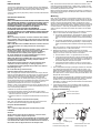
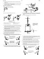
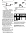
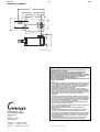
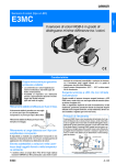
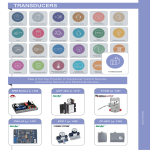
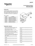
DS 3.325
05/02
MA40-704X-G0X
MF40-7043-G0X
MS40-7043-G0X
TM
4Nm SPRING RETURN ROTARY ACTUATORS
Invensys Spring Return Actuators have a rotary output for direct
coupling to air dampers. Models are available for on/off operation from
230Vac or 24Vac power supplies and 24Vac Floating Point Control.
There is also a 2-10Vdc input version that is fully modulating.
A special feature of the design is that mounting brackets, universal
joints and linking rods are not required for normal damper applications,
thus reducing installation and commissioning time.
FEATURES
• Direct coupling to all normal dampers without mounting
brackets or linkage kits - saves site time
• Universal clamp provides direct mounting to damper shafts up
to 15mm diameter or up to 13mm square (AM-710 accessory
clamp required when mounting actuators to shafts up to 19mm
diameter or 13mm square)
• Case to IP 54
• Clockwise and Counterclockwise rotation available,
determined by Left or Right Hand mounting
• Spring tensions whilst the damper is being operated
• Positive spring return operation, for example under power
failure
• Provides 95° of rotation; rotation limiting available
• Visual position indicator
• MX41-7043 Series actuators can be gang mounted to
accommodate high torque requirements
• Optional built-in auxiliary switches to provide for interfacing or
switching
• Cable Gland and Blanking plugs supplied fitted
• MS4X-7XXX Series provided with Left/Right switch for selection
of direct or reverse action control mode.
Notes:
Using Invensys damper actuators
The actuators listed in this data sheet are intended for the operation of
air dampers in HVAC systems.
Torque requirements
When calculating the torque required to operate dampers, it is
essential to take into account all the data supplied by the damper
manufacturer concerning cross sectional area, design, mounting and
air flow conditions.
Invensys is a trademark of Invensys plc and its subsidiaries and affiliates.
Multi-Lingual Instructions
MLI 3.325 - Installation Instructions
DS 3.325
2-8
05/02
SPECIFICATIONS
TYPE
MA40-7041-G00 MA40-7041-G01 MA40-7043-G00 MA40-7043-G01 MF40-7043-G00 MF40-7043-G01 MS40-7043-G00 MS40-7043-G01
POWER SUPPLY
- Voltage
- VA (60Hz)
- VA (50Hz)
- Watts (Running)
- Watts (Holding)
230Vac ±10%
6.0
8.3
5.4
2.6
24Vac ±20%
4.9
5.0
4.0
2.2
24Vac ±20%
8.1
8.7
4.0
2.2
ELECTRICAL
CONNECTION
24Vac ±20%
7.8
8.1
3.5
1.5
0.9m cable.
AUXILIARY SWITCH
-
INPUT CONTROL
SIGNAL
On-off, spring return. SPST control contacts or Triacs
(500mA rated).
24Vac
2 to 10Vdc @ 80kΩ
or
4 to 20mAdc @ 500Ω
Open/Close with single pole contact control.
Floating Point Control.
Proportional Modulation Control.
ACTION
POSITION FEEDBACK
One SPDT 6A
(1.5A) @
230Vac, UL
listed,
adjustable
0 to 95°
(0 to 1 scale).
-
One SPDT 6A
(1.5A) @
24Vac, UL
listed,
adjustable
0 to 95°
(0 to 1 scale).
95° ± 5° max. Adjustable (see end of stroke limits).
END OF STROKE
LIMITS
Stroke limiting device. Stop block adjuster used to limit angle of rotation from 40° to 95°.
DAMPER SHAFT
CLAMP
Universal mounting clamp used for shafts up to 15mm diameter, 13mm square.
Up to 0.74m2 based on 0.042 Nm per m2 of damper area (but see damper manufacturer’s specifications)
POSITION INDICATOR
Visual Indicator 0 to 1 (0 is spring return position).
<50s
<26s
<50s
<26s
AMBIENT
TEMPERATURE LIMITS
- Shipping & Storage
- Operating
<130s
<25s
-40 to 71°C
-30 to 50°C
HUMIDITY
15 to 95%rh non-condensing
PROTECTION CLASS
APPLICATION
One SPDT 6A
(1.5A) @
24Vac, UL
listed,
adjustable
0 to 95°
(0 to 1 scale).
Clockwise or Counterclockwise rotation, determined by Left/Right Hand mounting.
ANGULAR STROKE
AGENCY LISTINGS
-
4Nm (minimum)
DIRECTION OF
ROTATION
RUNNING TIME
(@ 21°C)
- Motor Operation
- Spring Return
One SPDT 6A
(1.5A) @
24Vac, UL
listed,
adjustable
0 to 95°
(0 to 1 scale).
MS40-7043: 2 to 10Vdc (max. 0.7mA) output signal for position feedback or to operate slave actuators.
OUTPUT TORQUE
NOMINAL DAMPER
AREA
-
IP 54
UL 873: Underwriters Laboratories (File # E9429 Category Temperature-Indicating and Regulating Equipment.
CUL: UL Listed for use in Canada by Underwriters Laboratories. Canadian Standards C22.2 No. 24-93.
European Community: EMC Directive (89/336/EEC). Low Voltage Directive (72/23/EEC).
Two-position control from a
thermostat, time switch or other
switching device having a mains
rated change-over contact.
Two-position control from a
thermostat, time switch or other
switching device having a 24V
rated change-over contact.
Floating Point Control.
Modulating control from any
controller providing a 2-10Vdc
positioning signal e.g. KMC,
CZT, DRTE, MMC, BAS, IAC,
MicroNet, Invensys Σ
ACCESSORIES
OPERATION
AM-674 - Weather Shield
AM-675 - Base Mounting Plate for AM-674
AM-676 - Universal Shaft Extension, to lengthen damper shaft by
229mm. Requires two AM-710 Universal Mounting Clamps.
AM-703 - Input Rescaling Module, adjusts signals to 2-10Vdc, zero and
span adjustment
AM-704 - Interface, pulse width modulation
AM-705 - Positioner
AM-706 - Min and/or Manual Positioner for flush panel mount
AM-707 - Digital Indication
AM-708 - 500Ω resistor for 0 to 20mA control signal
AM-709 - Damper Position Indicator
AM-710 - Universal Clamp for up to 19mm diameter shafts
AM-711 - Crank Arm for up to 13mm round shaft
AM-712 - Crank Arm Adaptor Kit
AM-713 - Mounting Bracket for Honeywell Mod IV, M6415 type
actuators, and new installations
AM-714 - Weather Shield (polycarbonate)
AM-715 - Crank Arm Adaptor Kit for Honeywell Mod IV M6415 type
actuators, and new installations
AM-756 - Metric Conduit Adapter M20 x 1.5 to 1/2” NPT
WARNING THESE ARE SPRING RETURN ACTUATORS. KEEP CLEAR OF
ALL MOVING PARTS AT ALL TIMES.
The direction of operation of the spring return function and motor
operation of all models is determined by left hand or right hand
mounting onto the damper.
All actuators are directly mounted onto the damper shaft using a
universal mounting clamp and provide true mechanical spring return
operation for reliable, positive close-off on air tight dampers. When
power is applied, the actuator moves to its powered position, at the
same time tensing the spring return safety mechanism. When the
power is removed, the spring returns the actuator to its normal position.
The spring return system provides consistent torque to the damper
with, and without, power applied to the actuator. All actuators provide
95° of rotation and are equipped with a graduated position indicator
showing 0 to 1.
Some models are provided with two built-in auxiliary switches. The
SPDT switches are provided for interfacing or signalling, for example,
fan start-up. The switching function is adjustable between 0° to 95°
rotation (0 to 1 scale).
05/02
3-8
INSTALLATION
The actuator is fitted directly to the damper and the clamp tightened
securely to the damper shaft. A universal anti-rotation bar is supplied
with each actuator and must be fitted to prevent rotation during
operation.
A stroke limiting device (stop block) is used to limit the stroke between
40 and 95°.
Precautions (General)
WARNINGS MA40-7041 SERIES ACTUATORS OPERATE AT MAINS VOLTAGE
AND THEREFORE PRESENT A POSSIBLE ELECTRICAL SHOCK
HAZARD. DISCONNECT THE POWER SUPPLY BEFORE AND
DURING INSTALLATION TO PREVENT ELECTRIC SHOCK AND
EQUIPMENT DAMAGE. OBSERVE LOCAL WIRING
REGULATIONS AND EARTHING REQUIREMENTS.
IF AUXILIARY SWITCHES ARE FITTED AND USED AT MAINS
VOLTAGE, OBSERVE LOCAL WIRING REGULATIONS, EARTHING
REQUIREMENTS AND ALL USUAL ELECTRIC SHOCK SAFETY
PRECAUTIONS.
Cautions
Where screening is required, use either screened cable or MICC.
Use an isolator with a minimum contact gap of 3mm (conforming
to EN 60335-1) to isolate the MA40-7041 series actuators from the
mains supply.
MA41-7043, MF41-7043 and MS40-7043 Series actuators must be
connected to 24Vac via a safety transformer conforming to
EN 60742.
MF40-704X and MS40-704X Series actuators contain a half-wave
rectifier power supply. They must not be powered with
transformers that are used to power other devices utilizing
non-isolated full-wave rectifier power supplies. Refer to
DS 10.250, Guidelines for Powering Multiple Devices from a
Common Transformer, for detailed information.
MA40-7043, MF40-7043 and MS40-7043 series actuators are not
recommended for applications needing multiple actuators
mounted on a common shaft.
Avoid electrical noise interference. Do not install near large
contactors, electrical machinery, or welding equipment.
For applications requiring flexible metal conduit, use reduced
(thin) wall types only.
Do not exceed ratings of the device(s).
Federal Communications Commission (FCC)
Note: This equipment has been tested and found to comply with the
limits for a Class B digital device, pursuant to Part 15 of the FCC Rules.
These limits are designed to provide reasonable protection against
harmful interference in residential installations. This equipment
generates, uses, and can radiate radio frequency energy and may
cause harmful interference if not installed and used in accordance with
the instructions. Even when instructions are followed, there is no
guarantee that interference will not occur in a particular
situation—which can be determined by turning the equipment off and
on—the user is encouraged to try to correct the interference by one or
more of the following measures:
• Reorient or relocate the receiving antenna.
• Increase the separation between the equipment and receiver.
• Connect the equipment to an outlet on a circuit different from that to
which the receiver is connected.
• Consult the dealer or an experienced radio/television technician for
help.
Canadian Department of Communications (DOC)
Note: This Class B digital apparatus meets all requirements of the
Canadian Interference-Causing Equipment Regulations.
European Standard EN 55022
Caution
This is a Class B digital (European Classification) product.
Location
Cautions
Avoid locations where excessive moisture, corrosive fumes,
vibration, or explosive vapours are present.
The actuator should only be mounted directly on the damper shaft
in locations that clear the maximum dimensions of the actuator
case and allow the actuator to be mounted flush to the surface of
the terminal box and perpendicular to the damper shaft.
DS 3.325
Note: Some terminal boxes have sheet metal screw heads or other
protrusions near the damper shaft. In these cases, a spacer or shim
may be added under the anti-rotation bracket of the actuator to make
the actuator perpendicular to the shaft.
Before mounting the actuator, determine the direction of rotation and
take into account the length of the damper shaft. These are covered in
the following section.
Mounting
Note: The zero (0) position on the position indicator is the normal or
spring return position. When the actuator is mounted with the 'R' side
facing the installer and the control system initiates actuator movement
(either by applying the appropriate voltage, increasing the control
signal or by driving the actuator open, as appropriate), the actuator will
rotate in the counterclockwise direction. Similarly, when the actuator is
mounted with the 'L' side facing the installer and the control system
calls for actuator movement, the actuator will rotate in the clockwise
direction.
1. Move the damper to its normal position. Check that the controller
action is set to match the damper application, as follows:
a. For normally closed damper - when damper is closed, actuator
position indicator should be approximately 0°. When damper is
open, the actuator position indicator should be approximately
90°.
b. For normally opened damper - when damper is open, actuator
position indicator should be approximately 0°. When damper is
closed, the actuator position indicator should be approximately
90°.
Note: The actuator is usually shipped with the universal mounting
clamp mounted to the 'L' side of the actuator.
2. Determine the direction of rotation required by the damper
application and ensure that the clamp is on the correct side; if the
clamp is not on the correct side, remount it as follows:
a. Find the letters 'R' and 'L' on opposite tabs on the clamp.
b. If mounting the actuator with the 'L' side out, position the clamp
so that the pointer section of the tab with the 'L' is positioned at
0 and the spline pattern of the clamp mates with the spline of
the actuator. Slip the clamp over the spline.
c. If mounting the actuator with the 'R' side out, use the same
procedure as for the 'L' side out, but use the 'R' tab instead of
the 'L' tab.
3. Test for adequate shaft length by sliding the actuator over the shaft.
The shaft should extend at least 3mm through the clamp. Long
shafts should be at least 90mm, in which case the clamp should be
fitted on the installer's side of the actuator, and short shafts should
be at least 20mm, in which case the clamp should be fitted to the
damper side of the actuator.
Note: All actuators are shipped with a standard universal mounting
clamp installed. For damper shafts larger than 16mm in diameter,
the AM-710 universal mounting clamp is required (order
separately). The AM-710 clamp accommodates round shaft sizes
up to 19mm in diameter.
4. If mounting the actuator on a long damper shaft, continue as
follows, otherwise follow the later procedure for mounting the
actuator on a short damper shaft (Step 8.).
Long Damper Shaft Mounting
10mm to 16mm square
10mm to 27mm diameter
Min. 90mm
Note: AM-710 required for shafts larger than 15mm diameter.
2
2
1
1
R
L
L
R
'R'
'L'
1. Universal mounting
clamp.
2. Retaining clip.
Clockwise motor drive
Counterclockwise motor drive
Counterclockwise spring return
Clockwise spring return
DS 3.325
4-8
05/02
5. Secure the universal mounting clamp to the actuator using the
retaining clip.
6. Position the damper at its normal (spring return) position and check
that it is fully closed or completely open.
7. Continue from Step 12. (Position Indication and Pre-tensioning).
Short Damper Shaft Mounting
Universal Bracket
10mm to 13mm square
10mm to 19mm diameter
Min. 20mm
90˚
Note: AM-710 required for shafts larger than 15mm.
2
L
2
3
3
R
15. Place a No.8 self-tapping screw in one side of the universal bracket
and mount it the duct at the base of the actuator. Do not tighten the
screw.
16. Pivot the universal bracket away from the actuator.
Centre line
L
1
1
2
R
C
L
2
'R'
'L'
1. Universal mounting clamp.
2. Retaining clip.
3. Damper position indicator
Clockwise motor drive
Counterclockwise motor drive
Counterclockwise spring return
Clockwise spring return
8. Determine the best orientation for the universal mounting clamp on
the back of the actuator. The best orientation provides the easiest
access to the two nuts on the V-clamp.
9. Engage the clamp to the actuator as close as possible to the
determined orientation, then lock the clamp in place using the
remaining retainer clip.
10. Place position indicator on the actuator and secure with the
retainer clip. Ensure that the position indicator is at the before
Pre-tensioning position (see following illustration).
11. Position the damper at its normal (spring return) position and check
that it is fully closed or completely open.
Position Indication and Pre-tensioning
0
1
.8
.6
.4
.2
With clamps loosened,
rotate approx. 5° away
from vertical, tighten
clamps, then return to
vertical
1.6 to 4.8mm
12. Slide the actuator over the shaft and verify that the position
indication pointer on the universal mounting clamp is in the normal
spring return position.
.4
.2
0
L
Correct universal clamp
pointer mounting position if
actuator is in normal spring
return position (before
Pre-tensioning)
.4
.2
R
Correct AM-709 pointer
mounting position if
actuator is in normal
spring return position
(before Pre-tensioning)
.4
.2
0
L
0
.4
.2
0
R
13. Tighten the universal mounting clamp, finger tight only.
14. Align the universal bracket at the base of the actuator and drill
mounting holes. Bend the bracket as needed to reach the duct.
17. Loosen the universal mounting clamp (making sure not to move
the damper shaft) and rotate the actuator approximately 5° in the
direction which would open the damper.
18. Tighten the universal mounting clamp to the shaft, ensuring that it
is in the correct mounting position.
19. Manually rotate the actuator to align with universal bracket.
20. Pivot the universal bracket into place and secure both sides.
21. Tighten all fasteners. Tighten the two nuts on the clamp using a
7/16" spanner or socket and apply 8.2 to 10.8 Nm of torque.
22. Check that the universal clamp (or AM-709) pointer mounting
position is at 5°.
23. Check that the universal mounting clamp (or AM-709) pointer
mounting position is at 5° (see following illustration).
.4
.4
Correct universal clamp pointer
mounting position (after 5°
Pre-tensioning)
.2
0
.2
L
.4
0
R
.4
Correct AM-709 pointer
mounting position (after 5°
Pre-tensioning)
.2
.2
0
0
L
R
05/02
5-8
DS 3.325
.
Installation of Universal Shaft Extension AM-676
Installation requires an AM-676 Universal Shaft Extension and two
AM-710 Universal Mounting Clamps for 19mm shafts. These items
must be ordered separately.
1
1
.8
.8
.6
.6
Actuator
.4
AM-710 Universal
Mounting Clamp
assemblies
Anti-rotation
bracket (included
with actuator)
L
.4
.2
.2
0
0
R
1
.8
.6
.4
.2
R
0
AM-676 Universal
Shaft Extension
Mounting surface
V-clamp
Duct
Damper shaft
AM-676 extends shaft
approx. 229mm.
1. Loosen the V-clamp nuts on the AM-676 universal shaft extension.
Fit the universal shaft extension fully onto the damper shaft and
tighten the universal shaft extension V-clamp nuts with a 10mm
open ended spanner. Apply 5.4 to 8.2 Nm of torque.
2. Position the damper at its normal (spring return) position. Verify
that the damper is fully closed or completely open.
3. Remove the mounting clamps from the actuator and replace them
with the AM-710 universal mounting clamps. Loosen the nuts on
both of the AM-710 universal mounting clamps.
4. Assemble the actuator onto the universal shaft extension, following
the same basic procedures as for 'Long Damper Shaft Mounting'
and 'Position Indication and Pre-tensioning ', taking into account
the direction of rotation required. Where 'universal mounting clamp'
is mentioned, substitute 'AM-710 universal mounting clamps'.
5. Ensure that the AM-710 clamps are tightened to 8.2 to 10.8 Nm of
torque.
Note: If the universal shaft extension protrudes excessively above
the actuator's top universal mounting clamp, remove the actuator
from the universal shaft extension, remove the extension from the
damper shaft and shorten the universal shaft extension by cutting
it to the desired length.
Jackshaft Installation (MA40-704X, MF40-7043, MS40-7043Series)
The MA40-704X, MF40-7043 and MS40-7043 series actuators are
designed for use with jackshafts up to 19mm in diameter. In most
applications, the actuator may be mounted in the same manner as a
standard damper shaft application. If the jackshaft diameter is larger
than 16mm in diameter, the optional AM-710 universal clamp must be
used.
Adjusting an Auxiliary Switch (where fitted)
The MA40-704X-G01, MF40-7043-G01 and MS40-7043-G01
actuators include one built-in SPDT auxiliary switch which can be used
for interfacing or signalling (e.g., for fan start-up). The switch is
adjustable between 0° and 95° of rotation (0 to 1 scale).
To make an adjustment:
1. The actuator must be in its normal (spring return) position.
2. Use a flat screw driver to rotate the switch pointer until it is at the
desired switch position on the 0 to 1 scale.
Rotation Limitation
The Stop Block is used in conjunction with the tab on the universal
clamp or the AM 709 position indicator. In order to function properly,
the clamp or indicator must be mounted correctly.
The Stop Block is used in applications where a damper has a designed
rotation that is less than 90°, for example with a 45° or 60° rotating
damper.
1. Determine the amount of damper rotation required. The actuator
stop block provides limited rotation from 40° to 95°.
2. Loosen the screw securing the stop block to the actuator.
Note: The actuator is shipped with the Stop Block mounted to the
'L' side. If the damper application requires the 'R' side face the
installer, simply remove the Stop Block and screw and move it to
the new location.
Adjusting Stop Block for Limited Rotation
3. Slide the stop block into position, so that its edge lines up with the
degree graduation on the actuator face which corresponds with the
required rotation.
4. Secure the stop block in place.
5. Test the damper rotation by applying power. Re-adjust if
necessary.
WIRING
Precautions
Class 2 control and power lead wiring must be routed separately from
line voltage wiring and any other non-class 2 circuits. Line voltage,
auxiliary switch and auxiliary switch leads must be connected to a
Class 1 circuit.
Actuator
Type
24Vac
24Vac
24Vac
230Vac
Spec Number
MA40-7043-G00
MA40-7043-G01
MF40-7043-G00
MF40-7043-G01
MS40-7043-G00
MS40-7043-G01
MA40-7041-G00
MA40-7041-G01
Maximum Wires Run (metres)
(5% Voltage Drop)
14 AWG
16 AWG
18 AWG
335
213
134
183
122
76
213
131
82
11,278
7,163
4,511
MAINTENANCE
A periodic check of the control system is recommended.
The spring power failure operations must be regularly checked by a
competent person and can normally be carried out as part of the
regular maintenance schedule. The spring checks are detailed below.
Depending on site operation, this check should be carried out at least
once every 6 months. If the checks are every 6 months then one of
them should be carried out at the start of the heating season.
Checking Power Failure Operation
WARNING HANDS SHOULD BE KEPT AWAY FROM THE ACTUATOR
DURING THIS OPERATION.
Remove all power from the actuator and check for correct spring
operation.
DS 3.325
6-8
05/02
CONNECTION DIAGRAMS
WARNING THESE ARE SPRING RETURN ACTUATORS. KEEP CLEAR OF ALL MOVING PARTS WHEN POWER IS REMOVED. ONLY SWITCH OFF
POWER IF SPRING RETURN IS REQUIRED.
TWO POSITION CONTROL - 230V
TWO POSITION CONTROL - 24V
MA40-7041-G00
MA40-7041-G01
Contact Closed: Actuator
turns against spring return
230Vac
MA40-7043-G00
MA40-7043-G01
Contact Closed: Actuator
turns against spring return
Brown
230Vac
Red
24Vac
(+)
0V
(-)
Light Blue
Black
Green/Yellow
Green/Yellow
Earth
Use an isolator with a minimum contact gap of
3mm (conforming to EN 60335-1) to isolate the
Provide overload protection
MA40-7041 series from the mains supply.
and disconnect as required.
Provide overload protection
and disconnect as required.
Connect via a 24Vac safety
transformer - see DS 25.001.
Parallel connection of several actuators is possible. Observe power consumption.
FLOATING POINT CONTROL - 24V
MF40-7043-G00
MF40-7043-G01
Low/High Limit
Thermostat
Red
24Vac
(+)
Connect via a 24V safety
transformer - see DS 25.001.
Black
0V
(-)
Provide overload protection
and disconnect as required.
Blue
Typical
Floating
Controller
Yellow/Black
Drive Open
Drive Closed
Green/Yellow
Earth
MODULATING CONTROL (2-10Vdc/4 to 20mAdc)
Connect via a 24V safety
transformer - see DS 25.001.
Provide overload protection
and disconnect as required.
MS40-7043-G00
MS40-7043-G01
Low/High Limit
Thermostat
Red
24Vac
(+)
Grey
(Note 3)
Control Signal
2 to 10Vdc
Notes:
1. Up to 4 actuators (mounted on
separate shafts) may be connected in
parallel. With four actuators mounted
to one 500Ω resistor, a 2% shift of the
control signal may be required.
Power consumption must be
observed.
2. A 500Ω resistor converts the 2-10V
signal to 4 to 20mAdc.
3. Only connect the common (grey) to
the negative leg of the control circuit.
4. To reverse actuator rotation, use the
reversing switch (MS40-7XXX).
Black
0V
(-)
(Note 2)
Yellow/Black
Blue
4 to 20mAdc
to other
actuators
Earth
Feedback
Signal
2 to 10Vdc
(Note 1)
L
R
Green/Yellow
AUXILIARY SWITCHES (IF FITTED)
230Vac
Actuator types: MA40-7041-G01,
MA40-7043-G01, MF40-7043-G01
and MS40-7043-G01 have one SPDT Aux Switch 1
6A (1.5A) 230V auxiliary switch
built-in for end position indication or
system interlock functions.
Use an isolator with a minimum
contact gap of 3mm (conforming to
EN 60335-1) to isolate the
MA40-7041 series from the mains
supply.
Yellow
Wire No.
NO
Violet
Orange
Motor terminals: see
appropriate wiring
diagram above.
Switch operating
position
NC
COM
0 to 1 scale, adjustable
WARNING AUXILIARY SWITCH MAY BE
AT MAINS POTENTIAL.
230Vac
05/02
7-8
DS 3.325
DS 3.325
8-8
05/02
DIMENSION DRAWING
202
172
149
120
6
25
80
100
50
93
19
125
19.5
87
61.5
6
Dimensions in mm
TM
Building Systems - UK
Invensys Energy Solutions
Farnham Road
Slough
Berkshire SL1 4UH
United Kingdom
Telephone +44 (0)1753 611000
Facsimile +44 (0)1753 611001
Web site
www.ies.invensys.com
WARNINGS THESE ARE SPRING RETURN ACTUATORS. KEEP CLEAR OF ALL
MOVING PARTS AT ALL TIMES.
CERTAIN MODELS (AND AUXILIARY SWITCHES WHERE FITTED)
OPERATE AT MAINS VOLTAGE AND THEREFORE PRESENT A
POSSIBLE ELECTRICAL SHOCK HAZARD. DISCONNECT THE POWER
SUPPLY BEFORE AND DURING INSTALLATION TO PREVENT ELECTRIC
SHOCK AND EQUIPMENT DAMAGE. OBSERVE LOCAL WIRING
REGULATIONS AND EARTHING REQUIREMENTS.
THESE ACTUATORS ARE NOT SAFETY DEVICES AND SHOULD NOT BE
USED ON FIRE DAMPERS.
Cautions
• Do not apply any voltages until a qualified technician has checked the
system and the commissioning procedures have been completed.
• If any equipment covers have to be removed during the installation of
this equipment, ensure that they are refitted after installation to
comply with UL and CE safety requirements.
• MF40-704X and MS40-704X Series actuators contain a half-wave
rectifier power supply. They must not be powered with transformers
that are used to power other devices utilizing non-isolated full-wave
rectifier power supplies. Refer to DS 10.250, Guidelines for Powering
Multiple Devices from a Common Transformer, for detailed
information.
• MF40-7043 series, MA40-7043 series and MS40-7043 series must be
connected to 24Vac via a safety transformer conforming to EN 60742.
• Use an isolator with a minimum contact gap of 3mm (conforming to
EN 60335-1) to isolate the MA40-7041 series from the mains supply.
• Ensure wires are not inadvertently crossed over.
• Carry out regular checks on the spring power failure operation as
detailed on Page 5 under Maintenance.
• Check torque requirements of damper (or other device) to be driven.
Do not exceed rated output torque.
• Interference with those parts under sealed covers renders the
guarantee void.
• The design and performance of Invensys equipment is subject to
improvement and therefore liable to alteration without notice.
• Information is given for guidance only and Invensys does not accept
responsibility for the selection or installation of its products unless
information has been given by the Company in writing relating to a
specific applications.
• A periodic system check of the control system is recommended.
Please contact your local Invensys service office for details.
© 2002 Invensys plc. All Rights Reserved.