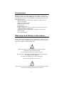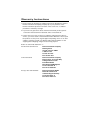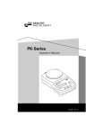
1
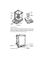
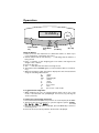
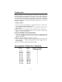
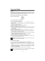
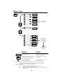
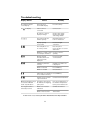
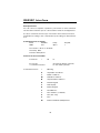
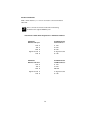
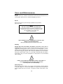
Apex Series Balances
Operation Manual
200
APX-0g x 0.1mg
20
nt
Instrume
Denver
00 g
ZERO
0.00
Print
Menu
I/O
902375.1 Rev. C
You have purchased a quality precision weighing instrument that
requires handling with care.
Read entire contents of this Operation Manual prior to operating
your new Denver Instrument balance.
Disclaimer Notice
Calibrate your balance using a reference weight of the appropriate
tolerance (class). An instrument can be no more accurate than the
standard to which it has been compared. For assistance in the selection of reference weights, please contact the factory.
!
Caution!
Changes or modifications not expressly approved by the manufacturer could void the user’s authority to operate this equipment.
!
Warning
Never lift balance by the weighing pan as this may cause
damage to internal mechanisms.
Always lift and transport the balance by its base, including
removal from packing materials!
Table of Contents
Specifications . . . . . . . . . . . . . . . . . . . . . . . . . . . . . . . . . . . . . . . . . . . . . . .ii
Introduction . . . . . . . . . . . . . . . . . . . . . . . . . . . . . . . . . . . . . . . . . . . . . . . . .1
Warning and Safety Information . . . . . . . . . . . . . . . . . . . . . . . . . . . . . . . .1
Getting Started . . . . . . . . . . . . . . . . . . . . . . . . . . . . . . . . . . . . . . . . . . . . . .2
Installation Instructions . . . . . . . . . . . . . . . . . . . . . . . . . . . . . . . . . . . . .2
Pan Assembly . . . . . . . . . . . . . . . . . . . . . . . . . . . . . . . . . . . . . . . . . . . .2
Connecting AC Power . . . . . . . . . . . . . . . . . . . . . . . . . . . . . . . . . . . . . .2
Leveling the Balance . . . . . . . . . . . . . . . . . . . . . . . . . . . . . . . . . . . . . . .3
Operation . . . . . . . . . . . . . . . . . . . . . . . . . . . . . . . . . . . . . . . . . . . . . . . . . . .4
Basic Weighing Function . . . . . . . . . . . . . . . . . . . . . . . . . . . . . . . . . . . .4
To toggle between weigh units . . . . . . . . . . . . . . . . . . . . . . . . . . . . . . .4
To select a weighing unit . . . . . . . . . . . . . . . . . . . . . . . . . . . . . . . . . . . .4
Calibration . . . . . . . . . . . . . . . . . . . . . . . . . . . . . . . . . . . . . . . . . . . . . . . . . .5
Acceptable Calibration Weights . . . . . . . . . . . . . . . . . . . . . . . . . . . . . . . . .5
Counting . . . . . . . . . . . . . . . . . . . . . . . . . . . . . . . . . . . . . . . . . . . . . . . . . . .6
Percent Weighing . . . . . . . . . . . . . . . . . . . . . . . . . . . . . . . . . . . . . . . . . . . .7
Advance Features Through Menu Codes . . . . . . . . . . . . . . . . . . . . . . . . . .8
Menu Tree . . . . . . . . . . . . . . . . . . . . . . . . . . . . . . . . . . . . . . . . . . . . . . . . .10
Troubleshooting . . . . . . . . . . . . . . . . . . . . . . . . . . . . . . . . . . . . . . . . . . . .11
RS232C Interface . . . . . . . . . . . . . . . . . . . . . . . . . . . . . . . . . . . . . . . . . . . .12
Hardware Handshake . . . . . . . . . . . . . . . . . . . . . . . . . . . . . . . . . . . . .13
Care and Maintenance . . . . . . . . . . . . . . . . . . . . . . . . . . . . . . . . . . . . . . .14
Accessories . . . . . . . . . . . . . . . . . . . . . . . . . . . . . . . . . . . . . . . . . . . . . . . .15
Gram Conversion Chart . . . . . . . . . . . . . . . . . . . . . . . . . . . . . . . . . . . . . .16
Warranty . . . . . . . . . . . . . . . . . . . . . . . . . . . . . . . . . .Inside Back Cover
i
Specifications
Analytical Models
APX-60
APX-100
APX-200
Toploading Models
APX-153
APX-203
APX-402
APX-602
APX-1502
APX-2001
APX-4001
APX-6001
Weigh Range
60g
100g
200g
Readability
0.1mg
0.1mg
0.1mg
Linearity
±0.2mg
±0.2mg
±0.2mg
Pan Size
3” dia. (76 mm)
3” dia. (76 mm)
3” dia. (76 mm)
150g
200g
400g
600g
1500g
2000g
4000g
6000g
0.001g
0.001g
0.01g
0.01g
0.01g
0.1g
0.1g
0.1g
±0.002g
±0.002g
±0.02g
±0.02g
±0.02g
±0.2g
±0.2g
±0.2g
4.5”dia. (114 mm)
4.5”dia. (114 mm)
4.5”dia. (114 mm)
4.5”dia. (114 mm)
4.5”dia. (114 mm)
5” x 7” (127 x 178 mm)
5” x 7” (127 x 178 mm)
5” x 7” (127 x 178 mm)
Common Specifications:
Dimensions ( L x W x H ) Analytical:
Dimensions ( L x W x H ) Toploading:
Net Weight Analytical:
Net Weight Toploading:
Power Requirements:
Operating Temperature:
Storage/Transport temperature:
Humidity:
Altitude:
12.6”x 8.7”x 12.8” (320 x 220 x 325 mm)
12.6”x 8.7”x 3.2” (320 x 220 x 76 mm)
9 lbs. (4.1 kg) (typical)
4 lbs. (1.8 kg) (typical)
15 VDC@100 mA with AC adapter, center pin (-).
15° - 40 °C
-10° - +40 °C
80% for temperature to 31°C, decreasing linearly
to 50% relative humidity at 40°C
3000m
Main supply voltage fluctuations not to exceed ±10% of nominal supply voltage. Equipment is suitable for continuous operation with AC adapter.
Pollution degree: 2; Installation category: II; Sound Pressure Level emitted by
equipment does not exceed ambient noise.
!
Caution:
Use AC adapter supplied with unit only!
Consult Denver Instrument Company for replacement.
ii
Introduction
APX-Series balances from Denver Instrument Company offer precision
weighing capacities from 60 to 6000 grams. These balances meet the highest requirements for accuracy and reliability of weighing results with versatile features such as:
• Efficient filtering-out of unfavorable ambient conditions such as
vibration and drafts
• Stable, reproducible results
• Ultra-fast response times
• Easy operation
• Multiple weigh units
• Rugged, durable construction suitable for educational, laboratory
and general industrial applications
• Toggle between four weight units, including one user-selected
• Piece Counting
• Percentage Weighing
Warnings and Safety Information
Read all of the Operation Manual prior to attempting to operate your precision balance. Connect only Denver Instrument accessories and options, as
these are designed for optimal performance.
!
Warning!
Make sure that the voltage rating printed on the AC adapter
is identical to your local line voltage.
Do not use this balance in a hazardous location.
The only way to turn power completely off is by disconnecting the
AC adapter from the balance.
Protect the AC adapter from contact with liquids.
This product is intended for indoor use.
!
Warning!
This unit has no user serviceable parts! Do not open the balance housing,
as this will invalidate the manufacturer’s warranty!
1
Getting Started
Thank you for choosing one of our precision instruments. Your balance is
designed and manufactured to the most rigorous standards in order to give
you years of service. First, check the contents of the shipping carton.
You should find the following:
•
•
•
•
•
•
•
Stainless-steel floor pan (analytical models only)
Drip ring (analytical models only)
Pan support
Cover pan
AC Adapter
Operation Manual
Warranty Card
Next, follow the instructions for installing your balance. To take advantage
of its many features, carefully read your operating manual. It contains stepby-step procedures, examples, and other vital information.
Finally, remember to return your completed warranty card within ten days
and retain a record of all purchase information.
Installation Instructions
Your balance is designed to provide reliable weighing results under normal
ambient conditions. When choosing a location to set up your new balance,
observe the following conditions to optimize ease and speed of use:
• Set up the balance on a stable, rigid and level surface
• Avoid locations subject to extremes in heat or direct exposure to sunlight
• Room temperatures above 105°F/40°C or below 60°F/15°C could affect balance operation and accuracy
• Protect the balance from direct exposure to drafts
• Protect the balance from aggressive chemical vapors
• Avoid strong magnetic fields present from other devices
• Avoid locations subject to vibration
• Avoid exposing the balance to excessive moisture for extended periods
• For best results, allow the balance to adjust to room temperature before
connecting to power source, for at least two hours
Pan Assembly
To avoid injury to your precision balance during shipping, the pan assembly
components were packed separately. Toploading models have a pan support and cover pan packed separately. Analytical models have a separate
floor pan and drip ring in addition to the pan support and cover pan. First
install the stainless-steel floor pan, followed by the drip ring (analytical models). Insert the pan support by centering over the pan stem, and finally install
the cover pan over the pan support.
Connecting the Balance to AC Power
When your new balance has reached room temperature, simply plug the AC
adapter into the rear of the balance and plug into an appropriate AC outlet.
“ ” is displayed in the upper left hand corner of the screen indicating the
balance is powered and in standby mode. Press the I/O key to initialize the
balance.
2
Cover
Pan
Cover
Pan
Pan
Support
Pan
Support
Drip
Ring
0.00
0g
ZERO
Print u
Men
I/O
Floor Pan
Leveling
Bubble
Leveling Foot
Leveling the Balance
Level the balance when first installing and when moving to a new location.
Adjust the leveling feet until the bubble is centered in the level indicator.
Then make sure alll feet are touching the countertop. The number of feet
varies per model: analytical and toploading models with round pans have 2
feet, toploading models with square pans have 4 feet.
Lockdown Tab
Leveling
Foot
AC adapter
connection
RS232C
Interface
Lockdown Tab
3
Operation
0.0000 g
ZERO
I/O
Print
Menu
Power On/Off
key
Print/Menu
key
Arrow
(scroll) key
Zero key
Taring the Balance
1. Press I/O to turn the instrument on. (Allow the balance to warm up to
room temperature, a minimum of 2 hours).
2. A brief self-test will be followed by “- -” indicating that the balance is
being zeroed.
3. Place a container on the weighing pan. The balance will register the
weight of the container.
4. Press the Zero key.
5. The “- -” indicates that the balance is being zeroed.
6. The balance will read 0.0000 grams (or selected units) after successful tarring.
7. When the reading is stable, the balance displays the unit of measurement
using the following abbreviations:
g
grams
GN
grains
dwt
pennyweight
oz
ounces
ct
carats
lb
pounds
ozt
troy ounces
tl
taels
pcs
pieces (see count mode)
To toggle between weigh units:
1. While weighing, the user can toggle between grams, pieces (see count
mode) a user-selected unit, pennyweight and ounces, by pressing the
arrow (scroll) key.
To change user-selected unit of measure:
1. Press and hold the Print/Menu key for three seconds. Display shows UNIT.
2. Then press the arrow (scroll) key to cycle through the options: c A r A t ,
L b , tr O Z , t A E L and gr AI n .
3. Once the desired weigh unit is displayed, press the ZERO key to return to
measuring mode.
4. Press the arrow (scroll) key until the desired unit is displayed.
4
Calibration
Always calibrate your balance after disconnecting from AC power source,
leveling the balance or moving the balance to a new location. Calibration
can only be performed when there is no weight on the balance, the balance
is tared and the internal signal is stable. If any of these three conditions is
not met, an error message will be displayed on the screen. The weight
required for calibration or adjustment will be displayed. (See accessories for
calibration weights).
To calibrate balance:
1. Press I/O to turn the instrument on. (Allow the balance to warm up to
room temperature, approximately 2 hours).
2. A brief self-test will be followed by the “- -” indicating that the balance is
being zeroed.
3. Remove all items from the pan and press the Zero key to tare balance.
4. Press and hold the Print/Menu key for three seconds or until “Unit”
appears on screen, then release.
5. Press the Print/Menu until “CAL” is displayed.
6. Press the arrow key to enter calibration mode.
7. The proper calibration weight needed for calibration is displayed on the
screen (ex +200.0000). The value is in grams. (See Acceptable Calibration
Weight chart below).
8. Place the indicated calibration weight on the pan.
9. When a stable reading has been recorded, the balance will beep, the
screen will flash “- -“ and the reading will return to the weight of the calibration weight.
10. Remove calibration weight and begin weighing.
Acceptable Calibration Weights
Model
Weight
APX-60
APX-100
APX-200
APX-153
APX-203
APX-402
APX-602
APX-1502
APX-2001
APX-4001
APX-6001
50 gram
100 gram
200 gram
100 gram
200 gram
200 gram
500 gram
1000 gram
2000 gram
2000 gram
5000 gram
5
Minimum Acceptable
ASTM Weight Class
2
2
2
2
2
3
3
3
3
3
3
Counting Mode
Counting
With the counting program you can determine a number of parts, each having approximately the same weight. A total weight is determined for 10, 20,
50 or 100 pieces. Using that weight in memory, as a “sample reference
quantity”, the balance weighs and counts similar pieces.
Factory default setting: Reference sample quantity: 10
Reference sample quantity:
10 pieces
20 pieces
50 pieces
100 pieces
To set count and reference quantity:
1. Press I/O to turn the instrument on.
2. A brief self-test will be followed by “- -” indicating that the balance is
being zeroed.
3. Press and hold the Print/Menu key for three seconds or until “Unit”
appears on screen, then release.
4. Press the Print/Menu until “Count” is displayed.
5. Press the arrow key to enter count mode.
6. Select the reference quantity to be counted by pressing the arrow key
until the correct quantity is displayed. The display cycles through: 10, 20,
50, 100, P100.0.
7. Press the Zero key to accept.
8. Remove all items from the pan and press the Zero key to tare balance.
9. Place the reference quantity on (ex. 10 pieces) balance and wait for a
steady reading (units will be displayed).
10. Press the arrow key. The balance will store this as the reference weight
and the display will show the current count.
11. Add uncounted parts. A total number of pieces is displayed.
12. Zeroing the balance will change piece count to zero.
13. Press the arrow key to display the total weight of pieces in grams, userselected units, pennyweight or ounces.
Switching from total number of parts counted to total amount of
weight, resets the reference weight.
Note:
Memo:
To reset reference weight:
1. Press the arrow key until the weight of the pieces is displayed.
2. Remove all items from the pan and add the correct reference quantity of
next pieces to be counted (see previous section to change reference quantity).
3. Press the arrow key until “––” appears on screen. The balance is accepting weight and making this the new reference weight. The total number
of pieces is now displayed.
4. Add uncounted parts. The total number of pieces is displayed.
When scrolling through units, the counting mode will be displayed
and reset only when there is weight on the pan.
Note:
Memo:
6
Percentage Weighing
This application allows you to obtain weight readout in percent proportional to a reference weight.
To set percentage weight:
1. Press I/O to turn the instrument on.
2. A brief self-test will be followed by “- -“ indicating that the balance is
being zeroed.
3. Press and hold the Print/Menu key for three seconds or until “Unit”
appear on screen, then release.
4. Press the Print/Menu until “Count” is displayed.
5. Press the arrow key to enter count mode.
6. Press the arrow key until P100.0 is displayed. The display cycles through:
10, 20, 50, 100, P100.0.
7. Press the Zero key to accept.
8. Remove all items from the pan and press the Zero key to tare balance.
9. Place the total weight on the balance and wait for a steady reading (units
will be displayed).
10. Press the arrow key until the display shows 100.00%.
11. Add or subtract parts and a percentage of the weight will be displayed.
12. Press the arrow key to display the total weight of pieces in grams, userselected units, pennyweight or ounces.
Switching from % to total amount of weight, resets the reference
weight.
Note:
Memo:
To reset reference weight:
1. Press the arrow key until the weight of the pieces is displayed.
2. Remove all items from the pan and add the new total weight.
3. Press the arrow key until “––” appears on screen. The balance is accepting weight and making this the new total weight. 100% is now displayed.
4. Add or subtract parts and a percentage of the weight will be displayed.
Note:
Memo:
When scrolling through units, the percent mode will be displayed
and reset only when there is weight on the pan.
7
Advance Features through Menu
Codes
Several advanced balance operations can be changed through menu
codes. Select the desired codes from the below list. Then follow the steps
the change the menu codes.
Special key functions in for menu code operation:
Zero- To enter/leave menu code settings, increased a number by one with
each press
Print- Moves to the next of three number of a code
To Change Menu Codes:
1. Press power key to turn balance off
2. Press power key to turn the balance back on. While all segments are displayed, press zero key once. After self-test, screen will have 1 on the left
side of display
3. Press zero key to increase the number on display to desired value
4. Press print for APX to move to the 2nd number of the code
5. Press zero key to increase the second number on display to desired
value
6. Press print for APX to move to the 3nd number of the code (when you
move to the third number, the previously set menu code will appear)
7. Press zero key to increase the third number on display to desired value
8. Hold down print for APX until “o” appears on the APX after the set
code. This confirms and stores the new code.
9. Press zero for more than 2 seconds to store the new menu code setting.
Menu Codes:
Filter Selection
1 1 1 Very stable conditions
1 1 2 Stable conditions (default)
1 1 3 Unstable conditions
1 1 4 Very unstable conditions
8
Baud
511
512
513
514
515
516
517
rate
150 baud
300 baud
600 baud
1200 baud
2400 baud
4800 baud
9600 baud (default)
Parity
5 2 1 Mark
5 2 2 Space (default)
5 2 3 Odd
5 2 4 Even
Stop Bits
5 3 1 1 stop bit
5 3 2 2 stop bits
Handshake Mode
5 4 1 Software
5 4 2 Hardware, 2 characters after CTS
5 4 3 Hardware, 1 character after CTS
Print
611
612
613
614
Configuration
Manual with print key without stability
Manual with print key after stability (default)
Manual with print key at stability
Auto print without stability
9
Menu Tree
Print
Menu
unit
grain
ZERO
carat
ZERO
lb
ZERO
tr oz
ZERO
Print
Menu
tael
ZERO
cal
“place
weight”
ZERO
“return to
weighing mode”
Print
Menu
count
10
ZERO
20
ZERO
50
ZERO
100
ZERO
P100.0
ZERO
“return to
weighing mode”
and add
reference weight
“accept reference
weight”
Function in
Weighing Mode
Function in
Menu Mode
ZERO
Zero’s the balance
Exits from current point weighing
mode, saves last options
Print
Menu
Pushed momentarily sends printer
string out optional serial port. Pushed
for 3 seconds enters menu mode.
Advances mode select to next
menu option.
Advances display options
to next clockwise option
Cycles through selections at
current menu level
Notes:
1. Text in quotes above indicates an action to occur (i.e., “place weight”)
2. Text not in quotes is the display message at that level (i.e., count or tael)
3. P100.0 is used to denote percentage weighing
Menu Level Functions:
unit
selects the units to be displayed when in free units mode
cal
calibrates the unit to the applied weight
count
selects the reference quantity that the applied load will represent and the
mode to operate in
10
Troubleshooting
Display Shows:
Cause:
Remedy:
No segments appear
on the display.
I/O key pressed
to turn OFF Display.
Press the I/O key.
no
Power cord not
connected.
Connect cord.
No power to outlet or
improper voltage.
Check power supply.
Check power supply
and voltage switch.
The load exceeds the
balance capacity.
Unload the balance or
look for obstruction.
Display capacity
is exceeded.
Decrease weight
on balance.
The load plate is not
in correct position.
Place the pan in
proper position or look for
obstruction
I
on display
––––
E 22
Weight is too light or there Increase reference
is no sample on balance.
quantity.
EO1
Display capacity
exceeded, value to be
output cannot be
displayed.
Decrease weight
on the balance.
EO2
Calibration parameter
not met.
Calibrate only when zero
is displayed.
Balance not tared.
Press TARE key.
Balance is loaded.
Unload balance.
E 11
Value input is not allowed
for second tare memory.
Press TARE key.
E 30
Interface port for printer
output is blocked.
Contact Denver Instrument
Maximum weighing range The balance was turned
is less than indicated
On without the weighing
under “Specifications”
pan in place.
Place the weighing pan on
the balance and press the
I/O key to turn balance On.
The weight readout is
obviously incorrect.
Balance has not been
calibrated.
Calibrate the balance.
Balance was not tared.
Tare balance.
If other errors occur, contact your Denver Instrument Service Representative.
11
RS232C Interface
Data Input Format
You can connect a computer or printer to your balance to send commands
via the balance interface port to control balance functions and application.
A control command can have up to 4 characters. Each character must be
transmitted according to the communication port setting for data transmission.
Communications Port Settings
Baud
Data Bits
9600
7bit
Parity
Space
Stop Bit
1
Flow Control = None or Xon/Xoff
Line Delay 50ms
Character Delay 50 ms
Format for Control Commands
Format: Esc
!
CR
LF
Esc: Escape
!: Command character
Command character:
CR: Carriage Return (optional)
LF: Line Feed (optional)
!
Meaning
K
Very Stable Conditions
L
Stable Conditions
M
Unstable Conditions
N
Very Unstable Conditions
O
Disable Keypad
P
Print Display
R
Enable Keypad
S
Reset Balance
T
Tare and Zero (combined)
U
Tare (tare only)
V
Zero
W
External Calibration/Adjustment
12
Hardware Handshake
With a 4-wire interface, 1 or 2 more characters can be transmitted
after CTS.
Note:
Memo:
These connections must be made when interfacing
the balance through the RS232C port!
Data Interface Cable Pin Configuration For APX-Series Balances
APX-Series
Balance 9-Pin port
Standard RS-232
9-Pin Connector
RxD 2
3 TxD
TxD 3
2 RxD
DTR 4
4 DTR
Signal Ground 5
5 Signal Ground
CTS 8
8 CTS
APX-Series
Balance 9-Pin Port
Standard RS-232
25-PIN Connector
RxD 2
2 TxD
TxD 3
3 RxD
DTR 4
20 DTR
Signal Ground 5
7 Signal Ground
CTS 8
5 CTS
13
Care and Maintenance
Service
Regular service by a Denver Instrument technician will extend the life of
your balance and ensure its continued weighing accuracy.
Repairs
Repair work must be performed by qualified factory-trained
personnel only.
Note
This unit contains no user serviceable parts.
All replacement parts should be obtained from the
manufacturer. Please refer to this manual for the
phone number of your sales and
service representative.
!
Warning!
Never lift balance by the weighing pan as this may cause
damage to internal mechanisms.
Always lift and transport the balance by its base.
Cleaning
Caution! Disconnect the balance AC adapter from power source prior to
cleaning. Make sure that no liquids enter the balance housing. Do not use
aggressive cleaning agents such as cleansers. A mild detergent is recommended. Disassemble the Pan Assembly (See page 3) and clean the floor
pan, breeze ring, pan support and cover pan separately, then reassemble.
Clean the balance with a piece of cloth. After cleaning, wipe the balance
down with a dry, soft cloth. Recalibration of the balance is recommended
after cleaning.
!
Warning!
If there are any indications that safe operation of the balance is
no longer warranted, turn off power and disconnect
from AC power source immediately.
Safety Inspection
Safe operation of the balance is no longer assured if there is visible damage
to the AC adapter or cord, the AC adapter no longer functions properly or
the AC adapter has been stored for a long period under unfavorable conditions.
14
Accessories
Draft Ring
In-Use Cover (analytical models)
In-Use Cover (round pan toploading models)
In-Use Cover (square pan toploading models)
Dot Matrix printer
9-Pin Cable
BalanceTalk XL Sinterface software
Calibration Weight - 50 grams
Calibration Weight - 50 grams
Calibration Weight - 100 grams
Calibration Weight - 200 grams
Calibration Weight - 500 grams
Calibration Weight - 1000 grams
Calibration Weight - 2000 grams
902191.1
602541.1
602542.1
602573.1
902280.1
400191.1
902227.1
870050.X
870050.X
870100.X
870200.X
870500.X
871000.X
872000.X
.X indicates Class:
.1 = ASTM Class 1
.2 = ASTM Class 2
.3 = ASTM Class 3
.4 = ASTM Class 4
.5 = OIML Class F1
.6 = OIML Class F2
.7 = ASTM Ulti-Mass
.8 = OIML Class E2
15
Gram Conversion Chart
1 Gram =
0.03527396
0.03215075
0.00220462
0.64301493
15.43235835
0.77161792
0.56438339
0.03527396
5.00000000
0.02671725
0.02645547
0.02666667
0.26666670
0.08573532
0.06596306
0.00980665
16
AV OZ
TROY OZ
POUNDS
PENNY WEIGHT
GRAIN
SCRUPLE
AV DRAM
AP DRAM
CARAT
TAEL (HK)
TAEL (S)
TAEL (T)
MOMME
TOLA
BAHT
NEWTON
Warranty Instructions
1. Please return the prepaid, pre-addressed Purchase Registration Card to
Denver Instrument Company promptly upon your purchase of the
Denver Instrument product. The return of the card is not a condition
precedent to warranty coverage.
2. If you have any questions about a Denver Instrument product, please
contact the nearest Denver Instrument office as listed below.
3. If it becomes necessary to return your Denver Instrument product for
service, you must obtain a “Return Authorization Number”. Please pack
the product securely in its original approved packing carton or an other
suitable container. Include your Return Authorization Number on the
shipping label. Shipping charges must be fully prepaid.
Return to authorized distributor or :
North and South America:
Denver Instrument Company
6542 Fig Street
Arvada, Colorado 80004
1-800-321-1135
Tel: 303-431-7255
Fax: 303-423-4831
U.K. and Ireland:
Denver Instrument Company
Denver House, Sovereign Way
Trafalgar Business Park
Downham Market
Norfolk PE38 9SW England
Tel: 44 136 63862 42
Fax: 44 136 63862 04
Europe, Asia and Australia:
Denver Instrument GmbH
Robert-Bosch-Briete 10
37079 Gottingen Germany
Tel: 49 551 20977 31
Fax: 49 551 20977 39
www.denverinstrument.com