1
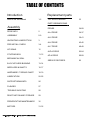
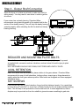
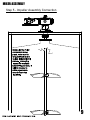
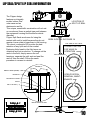
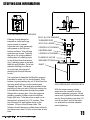
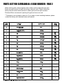
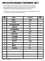
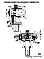
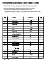
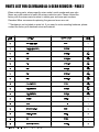
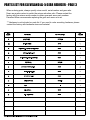
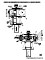
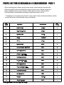
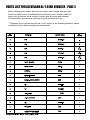
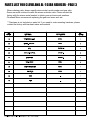
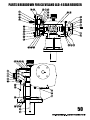
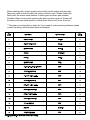
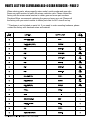
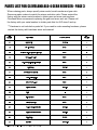
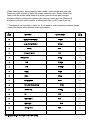
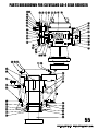
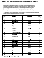
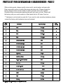
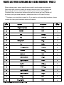
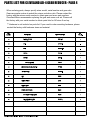
CLEVELAND MIXER
AL/ALD/AD Agitator Series
Models: AL - Single Reduction,
ALD - Double Reduction,
AD - Triple Reduction
www.clevelandmixer.com
Toll Free: 1-800-243-1188
Fax: 860-669-1199
09/25/2011 - J. NAARDEN
Cleveland Mixer 2012 rev5
AL / ALD / AD AGITATOR MANUAL
INSTALLATION,
OPERATION &
MAINTENANCE
Instructions for
TABLE OF CONTENTS
Replacement parts
Introduction
How to use this Manual
1-2
TOP ENTRY MIXERS
33
PARTS BREAKDOWNS
Assembly
DRIVE INFO
2
ASSEMBLY
5-9
UNCRATING & INSPECTION
3
PRE INSTALL CHECK
3-4
LIP SEALS
10
STUFFING BOX
11-12
MECHANICAL SEAL
12
B-LOC KEYLESS BUSHING
13-14
IMPELLERS & SHAFTS
15-17
HARDWARE / TORQUE CHART
18-19
LUBRICATION
20-25
SUPPORT BEAM INFO
26
FLANGES
27
TROUBLE SHOOTING
28
DEACTIVATION AND STORAGE
29
PREVENTATIVE MAINTENANCE
30
MOTORS
31-32
DRIVES
34-59
AL-4 DRIVE
34-37
AL-5 DRIVE
38-41
AL-6 DRIVE
42-45
AL-7 DRIVE
46-49
ALD-4 DRIVE
50-54
AD-4 DRIVE
55-59
SERVICE RECORDS
60
INTRODUCTION
HOW TO USE THIS MANUAL
This Owner's Manual provides information and instructions on the installation, operation and
maintenance of Cleveland Model AL, ALD and AD Mixers. The Table of Contents will help
you find any information you might need. To obtain maximum performance and trouble free
service from this Cleveland equipment, follow all instructions carefully. The Cleveland Mixer
Division of Subiaco offers installation service, maintenance seminars and aids in planning
spare parts programs. Contact Cleveland Mixer for details
UNIT RATINGS & APPLICATIONS
Operate mixer reducers only at the horsepower and speed indicated on the nameplate. All
"A" series mixers are designed to operate with the output shaft in a vertical position. Consult
Cleveland Mixer before making any changes in operating conditions of "A" series units,
differing from "as built".
WARRANTY
Cleveland Mixer warrants that, for a period of one year from the date of shipment, the
product described herein will successfully deliver its rated output as indicated in the
quotation, provided it is properly installed, maintained, correctly lubricated and operated in
the environment within the limits of speed, torque or other load conditions for which it was
designed. Unapproved modifications to the equipment and/or running the equipment in any
other way than what it was originally designed for voids the warranty.
The Cleveland Mixer warrantee applies to only items furnished by Cleveland Mixer. All other
equipment (tanks, mounting structures, power sources, process equipment) & designs are
the responsibility of others. Cleveland Mixer does not warrant, guarantee or assume any
responsibility for the design or construction of the mounting structure for the mixer.
HOW TO CONTACT US
For questions, tech support or parts & service:
Phone: 860-669-1199 or toll free 800-243-1188
Fax: 860-669-7461
Email: [email protected]
1
INTRODUCTION
IMPORTANT INFORMATION ABOUT YOUR AL DRIVE
Because of their unique worm and gear design, Cleveland "A" series worm
gear sets operate with multiple tooth contact at all times. This ensures
consistent power delivery. As a result, operation is smooth and extremely
quiet, normally in a sound range of 76 to 80 dBA.
Single reduction worm gear sets can easily provide gear reductions of 5:1
through 70:1, for output speeds down to 25RPM (using standard 1750
rpm motors). With double reduction helical-worm gear reducers, gear
reduction can go from 15:1 to 350:1 ratio to provide output speeds as low
as 5 rpm. This allows economical yet efficient mixing at lower speeds.
Please remember that gearing efficiency is quite different from mixing
efficiency. While mixing efficiency is influenced by gearing efficiency, it
also depends on other factors, such as the impeller and motor.
Cleveland "A" series mixer drives are engineered to withstand up to 300 %
momentary peak overloads and startup loads. Never start your mixer while
the impeller is buried in solids. The minimum service factor for Cleveland
"A" series mixer drives is 1.25.
Cleveland heavy duty "A" series drive units come equipped with heavy
duty Timkin roller bearings (B-10 life over 10,000 hours on the high
speed worm shaft; B-10 life of 100,000 hours on the low speed
shaft) which minimize shaft vibration and sensitivity to shaft deflection.
This eliminates the need for hollow quill construction.
2
INSTALLATION
Uncrating & Inspection
Be sure to use care when uncrating and handling the mixer. Certain parts
such as turbine hubs, turbine blades, couplings, steady bearings, seals,
hardware, spare parts and accessories may be packed in boxes or inside of
the crate.
Make sure all components are
accounted for before discarding the
packaging materials or crates. It is
common for parts to be missed or
overlooked.
The mixer should be carefully checked
for possible shipping damage at the
time of delivery. Any damage should be
reported immediately to the
TRANSPORTATION COMPANY AND
CLEVELAND MIXER.
Improper handling may cause damage
to the mixer and reduce the service life.
The shaft has been straightened to
within .003" per foot. Extra care should
be taken to see that it is not damaged in
the process of uncrating.
Lifting & Moving
Always use a crane, hoist or other mechanical assistance to move "A" series
units. Exercise care to prevent damage when moving. Lift only at designed lift
points. Insure that adequate safety measures are taken to protect personnel
during transportation. Protect the mounting surface from damage.
3
INSTALLATION
Pre Installation Check List
Most mixer operational problems can be
avoided by following the included installation
and operation instructions. The following is a
list of suggestions to help ensure proper
installation and therefore satisfactory mixer
service.
1 Before permanently wiring the motor,
check for the correct rotation of the
shaft. Standard rotation is clockwise
when looking down from the top.
Gear reducers reverse rotation, take
that into account when wiring. All wiring
should be done by a qualified
electrician.
2 Read and follow the instructions of all
tags and nameplates before operating.
3 Check the operating full load motor
amperage and voltage before operating
the mixer.
4 The mixers are designed to run against
a designed specific gravity. DO NOT
RUN THE MIXER DRY. Always test
run in fluid less than or equal to
designed specific gravity and viscosity
unless otherwise stated.
5 When starting the mixer, make sure
that the impeller is not buried in solids.
6 When making field changes of motor
horsepower, speed, shaft length,
impeller diameter, width, etc., consult
with Cleveland Mixer.
Before beginning work on any installation,
make sure you have all required parts. Keep
all parts for installation together at all times.
When Installing mechanical seals, please refer
to the seal the manual supplied with your
mixer.
4
MIXER ASSEMBLY
There are three styles of agitators
addressed in this manual; Open Tank,
Closed Tank and Sealed Tank.
Open tank models are typically
mounted to a pair of beams or bridge
work that traverse the tank. This
superstructure can be either
independent from the vessel or an
integral part of the tank itself.
Closed or sealed tank units are typically
mounted on ASA schedule nozzles and
incorporate some style of sealing
mechanism to contain pressure or
rogue emissions.
In either case, it is critical that the
mounting has a solid foundation which
can withstand the various forces
produced by the mixer. Excess
vibration and movement can damage
the mixer and the tank.
The mixer should be mounted to sit
level - 90° for vertical units.
We suggest laser aligning the shaft
from the hollow output of the reducer to
the bottom of the tank. Shaft alignment
will help to ensure the shaft will run
true. You do not want the shaft sitting
on even the slightest angle. An angled
or misaligned shaft can cause excess
vibration and speed wobble which can
damage the mixer and/or tank.
Be sure that the turbine blades can
freely rotate a full 360°. Be sure that the
blades will not come in contact with:
baffles, dip tubes, tank walls, etc. Refer
to approval drawings for clearance
information.
As previously mentioned; to ensure a long
service life and dependable performance, the
mixer must be rigidly supported and the shaft
accurately aligned. The shaft should not
move more than 1/32" per foot of shaft due to
deflection of the structure. It is important that
the gear reducer sits level for it's lubrication
system to work properly. Be sure to take into
account where the oil drain plug is before
mounting. The following describes the
minimum precautions required to accomplish
this end.
Before installing, take into account that your
mixer's gear reducer will require regular
scheduled maintenance and oil changes. Do
not install the mixer in an inaccessible area.
Do not seal the mixer into an area that does
not have enough room to drain and refill the
oil.
Foundation
The responsibility for the design and
construction of the foundation lies with the
user. The foundation must be adequate to
withstand normal operating loads along with
startup loads and shock loads while
maintaining alignment with attached system
components under such loads.
Concrete Foundation
If a concrete foundation is used, steel
mounting pads and bolts of sufficient size to
distribute the loads into the concrete should
be grouted into the foundation.
Steel Foundation
If a structural steel foundation is used, a base
plate of suitable thickness should be used
and should extend under the entire unit.
5
MIXER ASSEMBLY
Step 1 - Lower Shafting into Tank
The hub bore is machined within .005 - .015" tolerance of the
shaft diameter. Be careful not to ding, scratch or dent the
shaft when inserting it into the tank.
The shaft weight should be supported evenly to prevent
bending the shaft. The use of a crane and professional
riggers is recommended.
NEVER drop the weight of the
mixer drive or any other parts
on the shaft. The Mixer drive is
the only part of the mixer
designed to hold the weight of
the other components.
Step 2 - Brace Shafting
6
MIXER ASSEMBLY
Step 3 - Attach Drive to Tank Mount
Never support the mixer by the
ring eyelet on the motor.
It wasn't design to hold the weight
of anything but the motor.
7
MIXER ASSEMBLY
Step 4 - Output Shaft Connection
When the drive is in place use a level to make sure that it is
sitting evenly. You may need to use shims in order to get the
drive level.
If your mixer has a steady bearing, Cleveland Mixer
recommends using laser alignment of the output shaft to the
center of the steady bearing. This will help the steady bearing
operate properly while extending the life the shaft and steady
bearing bushing.
REDUCER AND MOUNTING PLATE BOLTS
These bolts are also subject to high loads and should be properly torqued to prevent
elongated bolts, excessive reducer vibrations, reduced mixer life and/or injury to plant
personnel.
ALL FASTENERS SHOULD BE CLEAN, RUST FREE AND LIGHTLY OILED.
AXIAL RETENTION
Each drive shaft must be retained in place relative to the gear reducer. Cleveland Mixer
recommends the use of shaft shoulders, locking collars, snap rings or fixing elements to
axially retain the shaft gear reducer position. Most units are designed and come equipped
with these items.
SET SCREWS
If set screws are used for axial retention, they should be tightened evenly. It is a good idea
to use a drop of "Lock-Tite" or some form of thread locker on the set screws before installing
them. This will help in the prevention of set screw back off. In some applications, flats or
dimples may be provided on the drive shafts to give set screws something to grab onto.
8
MIXER ASSEMBLY
Step 5 - Impeller Assembly Connection
9
LIP SEAL/SPLIT LIP SEAL INFORMATION
The Clipper design
features an integrally
LOCATION OF
molded rubber fiber
SPLIT LIP SEAL
outer case and an
elastomeric seal lip.
This unique, nonmetallic construction will not rust
or corrode and forms a gasket-type seal between
the equipment housing and the seal's outside
diameter.
Clipper Split Seals are known for being the
SEEN IN DETAIL IN FIGURE 1A
easiest split seal to install because they do not
require a cover plate to keep them in the housing.
TOP VIEW OF SPLIT SEAL
The robust, composite OD provides the best
CLOSED POSITION
retention of any split seal on the market.
FOR WHILE IN
Replacing failed seals in the field saves on
OPERATION
downtime and lost production. To change out the
seals in the field, simply remove the coil
COIL TENSIONER
tensioner, separate the split seal and peel the
seal off from the shaft. Follow the same
procedure in reverse to reinstall.
FIGURE 1A
NEMA FLANGE (MIXER)
OPEN POSITION;
REMOVAL, MAINTENANCE
PEDESTAL
MOUNTING FLANGE
SHAFT
SPLIT LIP SEAL ( 2)
INSTALLED SPLIT SEAL
10
STUFFING BOX INFORMATION
LOW PRESSURE STUFFING BOX
Packing should always be
inserted as individual rings,
never wound in a spiral.
Lubricate each ring generously
with grease on the top and
bottom surfaces. This will help
minimize run-in time. Typically
the set up for a high pressure
stuffing box is 3 packing rings
on the bottom then the lantern
ring, 4 packing rings on top and
then the split follower. For a low
pressure stuffing box, the set
up is typically two pieces of
packing with the split follower
on top.
BOLT & LOCK WASHER
THREADED ROD
SPLIT FOLLOWER
4 PIECES OF PACKING
LANTERN RING
3 PIECES OF PACKING
FLANGE W/ H.P.SB
GREASE FITTINGS
SHAFT
It is important to keep the Stuffing Box properly
lubricated in order for it to work properly. If the
lantern ring and packing dry out, friction from the
spinning shaft will burn up the packing and
damage the shaft. The sealing properties of the
packing will also not work if they are running dry.
Lubricate the stuffing box through the grease
fittings with a grease gun. Once the rings are
properly greased, tighten down the follower
finger tight only. Turn the mixer on and run at
atmospheric pressure for 5-10 minutes. Then
turn the mixer off and tighten down on the
follower 1/2 turn of the follower bolts. The
follower should always be pulled down uniformly
and never more than 1/2 turn on the bolts at one
time.
HIGH PRESSURE STUFFING BOX
With the mixer running, slowly
pressurize the vessel to its most
extreme operating pressure. At the
same time, tighten the follower bolts
slowly. Never tighten more than 1/2
turn at one time, and let the mixer
run at least five minutes between
each tightening.
11
STUFFING BOX CONT./MECHANICAL SEAL INFORMATION
The total amount of tightening will vary, depending on the degree of tamping, the operating
pressure and the density of the packing. Hard packing should seal in about one full turn of
the bolts. Softer packing may take two or more turns. If the stuffing box is not sealed after
one or two turns on the bolts, back off until they are loose and slowly add a pump of
grease through the fitting. Draw down the bolts until they are again just finger tight. Allow
the mixer to run for a few minutes, then resume the tightening process.
Do not tighten the packing beyond the point required to seal the box. Check the box two or
three times during the first 24 hours of operation. If it starts to leak, an additional 1/4 turn
should be sufficient to stop the leak in a minute or two.
After it has been installed and run in, the stuffing box should be periodically lubricated and
inspected for leaks. Do not wait for a leak to start before lubricating the box. Longer
packing life will be realized by preventing leaks through frequent lubrication. One pump of
grease from a hand held grease gun for a 2" diameter or larger shaft; somewhat less than
one pump for a smaller shaft. After some experience with the amount of grease required,
the lubrication interval can be shortened or lengthened. The unit can be lubricated while
the unit is running or off. It is a good practice to lubricate after a prolonged shutdown.
When a leak does occur, the first impulse should be to lubricate the packing, not tightening
the follower. The packing does not provide the seal, the lubrication does. Make sure the
lantern ring has adequate lubricant. Adding lubricant will often stop the leak within a
minute or so. If the box is still leaking after five minutes, the follower should be evenly
tightened a quarter turn until the leak stops.
MECHANICAL SEALS
In some applications, the use of a
mechanical seal may be necessary.
Refer to assembly drawing for seal
mounting info and the seal
manufacturer's manual for seal
maintenance.
Split mechanical seals allow for
maintenance or disassembly without
draining the tank and removing the
flange. Never remove a split
mechanical seal w/o a maintenance
manual specific to your model of seal.
We recommend that you also have a
rebuild kit or replacement seal handy.
12
B-LOC KEYLESS BUSHING
Keyless bushings are supplied lightly oiled and ready for installation (most open and
closed tank, vertically mounted mixers will have their B-Loc couplings factory installed).
When reinstalling a used coupling, make sure that all slits are aligned and that front and
rear clamp collars are not reversed. When the bushings are assembled correctly, there are
no holes or threads behind the taps in the clamp collar and no threads behind the taps in
the center collar. The frictional torque capacity of these devices is based on a coefficient:
friction - 0.12 for lightly oiled screws, taper and shaft & bore contact areas. NEVER use
Molybdenum Disulfide (e.g. Molykote, Never-Seize or similar lubricants) in any keyless
bushing installation.
STEPS TO INSTALL B-Loc KEYLESS BUSHING:
1. Make sure the locking screw, taper, shaft and bore contact areas are clean and lightly
oiled and that all of the collar slits are aligned.
2. Loosen all locking screws by a minimum of four turns and transfer at least two screws to
push-off threads in clamp collar to disengage this part from the center collar. Similarly,
transfer at least two screws to push-off threads in center collar to disengage this part from
the clamp collar.
3. Completed assembly can now be placed on the shaft and inserted into the hub bore by
pushing against the face of the collar while ensuring that the collar is not engaged at the
tapers during this phase.
4. After placement of the keyless bushing, relocate the locking screws used to separate
the collars.
5. Hand tighten the connection and confirm that the clamp collar is parallel with the face if
the part to be attached to the shaft and /or with the front facing edge of the center collar.
6. Use a torque wrench and set it approximately 5% higher than the specified torque value.
Tighten the locking screws using only quarter turns for several passes until quarter turns
can no longer be achieved.
7. Continue to apply over torque for one or two more passes. This is required to
compensate for a system-related relaxation of locking screws since tightening of a given
screw will always relax adjacent screws. Without over torqueing, an infinite number of
passes would be needed to reach specified tightening torque.
8. Reset your torque wrench to the specified torque and check all the locking screws. No
screw should be able to turn at this point. It is not necessary to recheck tightening torque
after equipment has been in operation.
**Note - When subjected to extreme corrosion, the slits in the clamp collars, as well as the
center collars, should be sealed with a suitable caulking compound or equivalent.
Likewise, push-off threads should also be protected from corrosion.
13
B-LOC KEYLESS BUSHING
STEPS TO REMOVE B-Loc KEYLESS BUSHING:
1. Check to ensure that axial movement of the clamp collars is not restricted. Check the
condition of the push-off threads.
2. Remove all of the locking screws. Transfer the required number of screws into all
push-off threads on the clamp collar.
3. Release the collar by progressively tightening down on all of the push-off screws. The
screws may appear to be completely tight after just one pass without any noticeable
separation of the clamp collars. Although it may seem like the screws cannot be tightened
further, several more rounds of torqueing in either direction will increase the push-off force
in the system and ultimately release part of the front collar.
4. Transfer the locking screws used for dismounting the clamp collar into all of the push-off
threads in the center collar. Release the clamp collar by repeating the procedures
described in step 3.
LOCKING SCREW SIZES AND TORQUE VALUES FOR KEYLESS BUSHING
STANDARD
METRIC
TORQUE VALUE - FT LBS
1 to 1-7/16"
25 x 55 to 35 x 60
12
1-1/2 to 2-9/16"
40 x 75 to 65 x 95
30
2-5/8 to 3-5/8"
70 x 110 to 90 x 130
60
3-3/4 to 4-3/4"
100 x 145 to 120 x 165
105
4-15/16 to 6.00"
130 x 180 to 160 x 210
166
6-7/16 to 8.00"
170 x 225 to 260 x 325
257
14
IMPELLERS & SHAFTS
NOTE: IT IS VERY
IMPORTANT THAT THE
BOLTS BE TORQUED TO
THE PROPER TORQUE
VALUE INDICATED IN THIS
MANUAL: PLEASE MAKE
SURE THAT YOUR
TORQUE WRENCHES
HAVE BEEN PROPERLY
CALIBRATED>Impellers and
turbines can have varied
number of blades. There
should be a blade for every
hub ear. Blades typically
mount to the bottom of the
ear. Check approval drawing
or call factory for
confirmation.
1. SINGLE IMPELLER INSTALLATION
NOTE: The extension shaft
and other machined parts
with close tolerances have
been straightened and
balanced to several
thousandths of an inch.
Please be careful when
handling and installing this
equipment.
NOTE: Keys have drill
points on one side for set
screw alignment.
To install any impeller,
simply slide the impeller
hub (top end of hub will
be marked top) onto the
shaft above the keyway.
Slide the hub back down
over the key until the hub
is positioned with the set
screw hole over the drill
point on the key. Firmly
tighten the hub set screw
into the key.
2. MULTIPLE IMPELLER INSTALLATION
15
IMPELLERS & SHAFTS
Now that the impeller hub is on the shaft, firmly bolt the impeller hardware (blades, discs,
stabilizers) into place. All in-tank fasteners should be rechecked for proper torque value
after 1500 hours of operation. It is also recommended to check for proper torque value at
scheduled shut down periods. All shaft and impeller bolts should be torqued to the values
shown in the torque value table in this manual.
The upper shaft or shaft section, if it is a multi-piece shaft assembly, will have either a
welded coupling, removable tapered bore coupling or B-Loc coupling that will mate with the
low speed shaft on the reducer.
The welded coupling is used on upper shaft sections for open tank mixers that do not have
any impellers mounted to it that would need to be removed. With a taper bore coupling, the
upper shaft is assembled to the taper coupling and held in place by the internal cap plate
bolted to the top of the shaft.
The rigid coupling is the welded flange type that requires no installation and would normally
be found attached to the upper shaft assembly, either in or out of the process. There may be
several of these connections between shaft sections in the assembly.
TAPER BORE COUPLING
RIGID COUPLING
B-Loc COUPLING
IMPELLER INSTALLATION
1. XTF-3R Impeller blades and hubs are shipped disassembled.
2. Slide the hub to the desired location over the key (the hub should be marked with "TOP"
make sure that side is up). Tighten the set screw over the key. Impellers over 50 inches in
diameter are provided with Gib keys. Lower the hub slowly until it rests on the Gib, then
tighten the set screw.
3. Assemble the blades to the underside of the hub using four hex head cap screws and nuts
per blade. Torque all bolts to the required specifications.
4. Retighten all bolted connections using proper torque settings before starting the mixer.
16
IMPELLERS & SHAFTS
Steady Bearings: When specified, mixers are supplied
with an optional in-tank steady bearing. A steady
bearing is an in-tank, process lubricated bearing used
to support and restrain the lower end of the mixer.
Steady bearings permit the safe use of smaller
diameter, longer shafts, operating at higher rotational
speeds. For proper steady bearing performance, the
mixer shaft must be straight and steady bearing must
be centered on the shaft. For pad type steady
bearings, be sure that the vessel top and bottom
flanges are parallel and concentric within .003" per
foot of separation. Shim bracket mounted steady
bearings between the bracket and bearing housing so
they stay centered on the shaft.
Even though a shaft may be
straight and properly machined,
it may appear to have
excessive run-out toward the
bottom. For longer shafts
(20-30') 1/2 the shaft
diameter may be acceptable.
However, for shorter shafts, the
run-out should not exceed 1".
For best results, the
steady bearing should be
laser aligned with the
reducer quill and welded
to tank. The steady
bearing bushing should be
inspected for wear during
every shut down period. If
the bushings are worn
down to the metal of the
bushing housing, they
should be replaced. Call
Cleveland Mixer with your
mixer's serial number for
replacement bushings.
STEADY BEARING - Bushing and
bushing housing should be checked
periodically for excessive wear. If your
installment alignment is precise, you
will experience less bushing wear.
STANDARD - Impellers
should rotate clockwise
when looking down from
the top. When wiring,
take into account that
gear reducers reverse
rotation. Follow the
motor wiring guide for
wiring instructions. Wires
may need to be switched
in order to reverse rotation.
Always check rotation
before putting your mixer
into operation.
STEADY BEARING
17
IMPELLERS & SHAFTS
KEYLESS RIGID COUPLING
Keyless Rigid Couplings eliminate the need for shaft keys and keyways. Keyless rigid
couplings will come with their own set of installation instructions specific to the size and
style of coupling required for your mixer's design.
HARDWARE
TORQUE VALUES FOR THRUST BOLTS
BOLT SIZE
1/2 - 13
5/8 - 11
3/4 - 10
7/8 - 9
1-8
1 - 1/8 - 7
1 - 1/4 - 7
1 - 3/8 - 6
1 - 1/2 - 6
1 - 3/4 - 5
2 - 4 - 1/2
2 - 1/4 - 4 - 1/2
2 - 1/2 - 4
ALL MATERIALS
NUMBER
FOOT POUNDS
50
68
90
122
160
217
140
190
220
298
300
407
420
570
754
556
740
1003
825
1118
1125
1525
1725
2338
2300
3117
* Lubricate bolt before installation. Torque each bolt to
the appropriate value as shown above.
NOTE: The bolt torques shown here will develop a fastener pre load of 80 % of the fastener's
minimum yield.
COUPLING BOLTS - LOW SPEED SHAFT: At least Grade 5. The torque required may be
found using the Grade 5 chart and reading across from the bolt diameter to be used. If
stainless bolts are used, proceed with the proper stainless steel chart. Any looseness in
these bolts causes the coupling to apply a shear load on the bolt and a high impact tensile
load or shock load.
This shock load and shear load can cause the bolts to snap, the holes to elongate or the
coupling to fail to keep the shaft running straight which can have numerous and permanent
damaging effects on the mixer.
18
HARDWARE
TORQUE VALUES FOR RIGID CONNECTIONS
CARBON STEEL
BOLT
SIZE
3/8 - 16
1/2 - 13
9/16 - 12
5/8 - 11
3/4 - 10
7/8 - 9
1-8
1 - 1/8 - 7
1 - 1/4 - 7
1 - 3/8 - 6
1 - 1/2 - 6
Grade 2
FT-LB
Nm
15
20
38
51
50
68
68
92
120
163
105
143
165
224
225
305
315
428
417
566
555
752
Grade 5
FT-LB
Nm
23
30
77
56
83
112
113
152
200
271
296
401
443
601
596
808
840
1139
1003
1495
1463
1983
Stainless Steel, Alloy 20,
Monel, Hastelloy C
FOOT-LBS
15
37
54
74
131
212
318
450
636
834
1470
NUMBER
21
50
72
101
178
287
432
610
862
1130
1500
NOTES:
1. Tighten all fasteners to the values shown unless specifically instructed to do otherwise.
2. Lubricate all fasteners at assembly with grease, oil or anti-seize material.
3. If fasteners cannot be lubricated, multiply table values by 1.33
19
LUBRICATION & PLUGS
**IMPORTANT - AL style reducers are shipped
without oil. ADD OIL BEFORE STARTING
Use an oil grade and viscosity in accordance
with AGMA standards. Cleveland Mixer
recommends Mobil Lubricants. Use the sight
gauge or oil plug to fill the gear case to the
proper level. Please refer to pages 21-22 in this
manual for additional lubrication information.
FILL LEVEL & DRAIN PLUGS
The drain plugs are socket head cap screws. They will be
located at the lowest part of the gearbox for ease of draining.
Fill Level Plug
Drain Plug
Sight Guage
GREASE FITTINGS
Add grease to high speed and slow speed bearings through
grease fittings. AL reducers will come with grease fittings
pre-installed in the appropriate locations. Bearing greases must
be compatible with the type of gear lubricant being used (i.e.
mineral, synthetic, food grade, etc.).
For mineral oils, use a synthetic bearing grease such as Mobil
Synthetic Universal grease, Mobilith SHC 100 or suitable
equivalent. Add grease as needed to keep bearings properly
lubricated. Do not over pump grease into the grease fittings.
Grease Fitting
20
LUBRICATION INFO
INSTALLATION
Proper installation or your worm gear speed reducer is essential for efficient,
economical operation and a long operating life. The unit is built for proper
operation in the mounting position ordered. Tilted or different mounting
positions may require factory installed lubrication provisions.
Proper lubrication is crucial to obtaining the highest possible performance and
efficiency. All "A" series mixer drives are shipped from the factory WITHOUT oil.
Due to the nature of the worm gear's sliding and rolling actions, the lubricants
listed on the next page must be used.
OIL CHANGES
Check the oil level while the unit is not in operation. Add oil when the oil level
has gone below the fill line **Make sure to never mix oils. Drain and flush the
gear housing after the first 150 hours of operation.
The regular maintenance schedule should be as follows:
Drain the oil and flush after every 6 months of normal service (8 hours of
operation per day - 7 days per week, normal operating temperature).
Drain the oil and flush after every 3 months of heavy service (24 hours - 7
days per week) or (8 hours per day - 7 days per week in extreme
temperatures or extreme environments).
GREASE LUBRICATED BEARINGS
All input and output bearings used in Cleveland's "A" series mixers are factory
packed with NLGI grade 2 grease. This grease is mineral based with lithium
base thickener. Repack the bearings using the same grade of grease during all
normal oil change intervals.
Lubricants that should NEVER be used in the oil well of the reducer:
1. Motor Oil
2. Automotive Gear Oil
3. Grease
4. EP Oils
21
LUBRICATION INFO
CLEVELAND APPROVED LUBRICANTS
COMPOUNDED STEAM CYLINDER OIL
MANUFACTURER
AGMA #7C
AGMA #8C
AMOCO CHEMICAL CORP.
AMOCO CYLINDER OIL NO. 460
AMOCO CYLINDER OIL NO. 680
ASHLAND OIL INC.
LIGHT CYLINDER
NO PRODUCT
ATLANTIC RICHFIELD CO.
NO PRODUCT
MODOC 175
BP
ENERGOL DCC 460
ENERGOL DCC 680
CHEVRON
CHEVRON CYL. OIL ISO 460
CHEVRON CYL. OIL ISO 680
CITGO
CITGO CYL. OIL 400-5
CITGO CYL. OIL 680-7
CONTINENTAL OIL CO.
INCA OIL 460
INCA OIL 680
EXXON
CYLESSTIC TK 460
CYLESSTIC TK 680
IMPERIAL OIL LTD.
CYLESSO TK 460
CYLESSO TK 680
KEYSTONE
NO PRODUCT
KEYGEAR K600
MOBIL ( USA)
600W CYLINDER OIL
600W CYLINDER OIL
MOBIL ( CANADA)
600W CYLINDER OIL
600W CYLINDER OIL
PHILLIPS PETROLEUM CO.
HECTOR 460S
HECTOR 630S
SHELL OIL CO.
VALVATA OIL J 460
VALVATA OIL J 680
SHELL ( CANADA)
VALVATA OIL J 460
VALVATA OIL J 680
TEXACO
VANGUARD CYLINDER OIL 460
VANGUARD CYLINDER OIL 680
UNION OIL CO.
UNION STEAVAL B110
UNION STEAVAL B165
MANUFACTURER
AGMA 7 SYNTHETIC
AGMA 8 SYNTHETIC
Klubersynth
Gem 4-460N
Gem 4-680N
Mobil Oil Corp.
SHC 634
SHC 636
Petro Canada
Syndro SHB 460
No Product
.
INCLUDES BRANDS ALREADY TESTED FOR EFFECTIVENESS AND APPROVED BY MFG.
BEARING GREASE
SHELL
SHELL DURINA SD2
NLGI Grade 2
22
LUBRICATION INFO - AL SERIES
GEAR CASE OIL
All units are shipped from the factory
WITHOUT oil. Units should be filled to
the level plug.
Check oil level periodically when the
unit is not operating. Add oil if
necessary. Drain and flush housing
after first 150 hours of operation.
Drain the oil and flush after every 6
months of normal service or after
every 3 months of heavy or severe
service (around the clock operation
or harsh operating environment). If
ambient temps are below 15° F, a
winter lubricant must be added since
AGMA 7 & 8 oils will solidify.
Suppliers of industrial lubricants
should be contacted to supply suitable
lubricants to meet AGMA
specifications (please see page 22
for oil recommendations).
Reliefe vent
Sight guage
Oil drain plug
BEARING GREASE
Grease Lubricated Bearings - The low speed shaft bearings are provided with grease fittings. These
bearings are packed at assembly with lithium based grease NLGI grade 2 with EP additives.
(Cleveland recommends Mobil or Shell - Durina SD2 / NLGI grade 2 bearing grease).
Fill Line
Grease fitting for low speed bearing
(some units may have
several grease fittings
on both the reducer, motor
and stuffing box. Make
sure to grease all zerk
fittings on gear case).
23
LUBRICATION INFO - ALD SERIES
GEAR CASE OIL
All units are shipped from the factory
WITHOUT oil. Units should be filled to
the level plug.
Check oil level periodically when the
unit is not operating. Add oil if
necessary. Drain and flush housing
after first 150 hours of operation.
Drain the oil and flush after every 6
months of normal service or after
every 3 months of heavy or severe
service (around the clock operation
or harsh operating environment). If
ambient temps are below 15° F, a
winter lubricant must be added since
AGMA 7 & 8 oils will solidify.
Suppliers of industrial lubricants
should be contacted to supply suitable
lubricants to meet AGMA
specifications (please see page 22
for oil recommendations)
Sight guage
Oil drain plug
BEARING GREASE
Grease Lubricated Bearings - The low speed shaft bearings are provided with grease fittings. These
bearings are packed at assembly with a lithium base grease NLGI grade 2 with EP additives.
(Cleveland recommends Mobil or Shell - Durina SD2 / NLGI grade 2 bearing grease)
Fill Line
Grease fitting for low/high
speed bearings
(some units may have
several grease fittings
on both the reducer, motor
and stuffing box. Make
sure to grease all zerk
fittings on gear case.)
24
LUBRICATION INFO - AD SERIES
GEAR CASE OIL
All units are shipped from the factory
WITHOUT oil. Units should be filled to
the level plug.
Check oil level periodically when the
unit is not operating. Add oil if
necessary. Drain and flush housing
after first 150 hours of operation.
Drain the oil and flush after every 6
months of normal service or after
every 3 months of heavy or severe
service (around the clock operation
or harsh operating environment). If
ambient temps are below 15° F, a
winter lubricant must be added since
AGMA 7 & 8 oils will solidify.
Suppliers of industrial lubricants
should be contacted to supply suitable
lubricants to meet AGMA
specifications (please see page 22
for oil recommendations)
Sight guage
Oil drain plug
BEARING GREASE
Grease Lubricated Bearings - The low speed shaft bearings are provided with grease fittings. These
bearings are packed at assembly with a lithium base grease NLGI grade 2 with EP additives.
(Cleveland recommends Mobil or Shell - Durina SD2 / NLGI grade 2 bearing grease)
Fill Line
Grease fitting for low/high
speed bearings
(Some units may have
several grease fittings
on both the reducer, motor
and stuffing box. Make
sure to grease all zerk
fittings on gear case.)
25
SUPPORT BEAM RECOMMENDATIONS
LATERAL BRACING - SAME
SIZE AS MAIN BEAMS
MIXER MOUNTING HOLES
1. If the design load exceeds the actual
loads by a factor consistent
with construction codes. If the
recommended beams are to carry loads in
addition to the mixer, larger beams may be
required.
2. Cleveland Mixer warranty applies only to
items supplied by Cleveland Mixer.
Cleveland Mixer does not assume any
responsibility or liability for the design or
construction of the tank, mounting structure,
electrical system or any other equipment
not manufactured by Cleveland Mixer.
CLOSE OFF BEAMS
AT BOTH ENDS
Support beams should be bridged over the
tank and be supported by a solid surface.
Tanks often vibrate. If the support bridging
is only supported by the tank, the mixer will
not have the rigidity it needs to operate.
Even if your tank is made from steel, when
thousands of gallons start moving around,
the tank can vibrate, pulsate, sway,
etcetera. Those events can create forces
and movement that the shaft and impellers
were not designed to handle.
MOUNTING PLATE
w/ CENTER HOLE FOR SHAFTING
BRIDGING
USE MOUNTING BOLTS
AND WELDS TO HOLD
MOUNTING PLATES IN
PLACE. THE MORE
RIGID YOUR MOUNTING
PLATE THE BETTER YOUR
MIXER WILL PERFORM.
TANK
SUPPORT BEAMS SHOULD BRIDGE TANK AND COME UP
FROM THE GROUND OR FLOOR
26
FLANGE CONNECTIONS
STANDARD 150 LB. FLANGE
NOMINAL
PIPE
SIZE
OUTSIDE
DIAMETER
OF FLANGE
-O-
THICKNESS
DIAMETER
NUMBER
OF
FLANGE
-Q-
OF
RAISED FACE
-R-
DIAMETER
DIAMETER
APPROX.
OF
BOLT HOLES
OF
BOLTS
OF
BOLT CIRCLE
WEIGHT
IN LBS
4
9.00"
15/16"
6-3/16"
8
5/8"
7-1/2"
17#
5
10.00"
15/16"
7-5/16"
8
3/4"
8 -1/2"
20#
6
11.00"
1.00"
8-5"
8
3/4"
9 -1/2"
27#
8
13.50"
1-1/8"
10-5/8"
8
3/4"
11-3/4"
47#
10
16.00"
1-3/16"
12-3/4"
12
7/8"
14-1/4"
67#
12
19.00"
1-1/4"
15-00"
12
7/8"
17.00"
102#
*150 LB. Blind Flanges - All dimensions are given in inches. Flanges are furnished faced,
drilled and spot faced or back faced.
Bolt holes are 1/8" larger than bolt diameter.
The 1/16" raised face is included in dimension "Q"
1/16" RAISED FACE
27
TROUBLE SHOOTING
RUNS HOT
PROBLEM WITH THE REDUCER
Overloading
Improper Lubrication
RUNS NOISY
Loose Foundation Bolts
Bearing Failure
OIL LEAKAGE
OUTPUT SHAFT
DOESN'T TURN
Insufficient Lubrication
Internal Parts
are Broken
POSSIBLE CAUSES
SUGGESTED REMEDY
Check rated capacity of reducer,
Load exceeds the
capacity of the reducer replace with unit of sufficient capacity
or reduce load
Insufficient Lubrication Check lubrication level and
adjust down to recommended level
Excessive Lubrication Check lubrication level and
adjust down to recommended level
Flush out and refill with correct
Wrong Lubrication
lubricant as recommended
Inspect mounting of reducer.
Weak Mounting
Tighten loose bolts.
Structure
Reinforce mounting structure
Loose hold down bolts Tighten bolts
May be due to
lack of lubricant
Replace bearing. Clean and flush
reducer and fill with recommended
lubricant.
Overload
Check rated capacity of reducer
Level of lubricant
inside the reducer not
properly maintained
Check lubrication level and
adjust down to recommended level
Overloading of
a reducer
can cause damage
Replace broken parts. Check rated
capacity of reducer.
Key missing or sheared Replace key
off in input shaft
Coupling loose or
disconnected
Properly align reducer and
coupling. Tighten coupling.
Caused by dirt or
grit entering seal
Replace seals.
Overfilled reducer
Worn Seals
Improper mounting
position, such wall or
ceiling mount
horizontal reducer
Check lubricant level and adjust to
recommended level.
Clean or replace, being sure to
prevent any dirt from falling into
the reducer.
Check mounting position to
approval drawings
DEACTIVATION & STORAGE
DEACTIVATION
SHORT TERM SHUTDOWN - Units may be deactivated and left offline for up to four
months without special precautions.
LONG TERM SHUTDOWN - If the unit is to be deactivated or stored for more than four
months after any period of operation:
1. Indoor dry storage is recommended for all inactive units. Deactivated units stored
outdoors should be protected from the weather. It is most important to keep the unit dry
and in a temperature controlled area.
2. Drain the oil from the unit and spray the inside of the gear case with a long term storage
lubricant such as "Motorstor" or a suitable vapor phase rust inhibitor at the rate of one
ounce per cubic foot. Make sure to mark the gearbox appropriately so that the storage
lubricant is drained and the gear case is refilled with the proper lubricant before restarting.
3. Mixer shafts should be removed and coated with Cosmoline or suitable preservative
(even stainless steel shafts should be coated where they come into contact with steel or
banding straps). Make sure the shafts are properly supported to prevent bending. It is
good to rotate the shafts periodically to keep them from settling in one position which can
cause them to bend. When storing carbon steel parts outdoors, apply suitable grease or
rust preventative to all parts. Turbine parts should also be coated with preservative,
especially the bore of the turbine hub.
4. Motors should be stored in a cool, dry environment. The motor shaft should be rotated
once each month.
5. Inspect stored or inactive units at 90 day intervals. Re-spray with rust preventative or
add rust inhibitor at least once every six months as required.
29
PREVENTATIVE MAINTENANCE
PREVENTATIVE MAINTENANCE CONTINUED
The first week after startup / restart: Check all external fasteners and plugs for proper
torque.
Gears and internal bearings have been factory set and require no adjustments. Driven
shaft bearings require no maintenance other than periodic regreasing.
NOTE: If the oil level has risen since the previous check, have the oil analyzed for water
content. Moisture in the oil may indicate seal leakage or condensation. Drain the oil,
correct the defect and refill the unit with fresh oil.
Mineral lubricant should be changed every 10,000 service hours or after two years of
service. For synthetic oils, the lube should be changed every 20,000 service hours or after
four years. In cases of extreme operating conditions (e.g. high humidity, aggressive
environment or large temperature variations) shorter intervals between changes are
recommended.
OPERATION & MAINTENANCE CHECKLIST
1. Operate the equipment as it was intended to be operated.
2. Do not overload
3. Run at correct speed
4. Maintain lubricant in good condition and at proper level.
5. Apply proper maintenance to attached equipment at prescribed intervals recommended
by Cleveland Mixer.
6. Perform periodic maintenance of the gear drive as recommended by Cleveland Mixer.
STANDARD OIL - INDICATED ON THE SIDE OF THE REDUCER.
* DO NOT MIX OILS. ALWAYS DRAIN UNIT COMPLETELY BEFORE
USING A NEW GRADE OR BRAND OF OIL. MIXING MINERAL OIL AND
SYNTHETIC OIL IN THE SAME WELL MAY CAUSE PERMANENT
DAMAGE TO GEAR REDUCER.
30
MOTOR INFO
Cleveland Mixer mixers are supplied with motors
manufactured by nationally known sources. Under normal
operating conditions, within specified temperatures, proper
installation and maintenance, these motors will deliver their
rated output.
If the mixer will be operating in a particularly harsh
environment (e.g. extreme temperatures, high levels of
dust, etc.) please contact Cleveland Mixer before operating
your mixer. Standard motors are fan cooled which may not
be the right motor for your application.
To get the best performance and a long service life from your electric motor, be sure there is
plenty of air circulation and a minimum of obstructions. On fan cooled motors, be sure not to
choke off the suction inlets. Also be sure to check the allowable temperature, amp draw,
horsepower and voltage indicated on the motor plate.
Always consult Cleveland Mixer before making changes to your process. Your mixer was
designed to run in a process. Changes to this process can be detrimental to the proper
operation of your mixer.
To avoid damage to the motor during temporary overloads, jams, etc., be sure overload
protection is provided. Starter overload heater elements can be sized from the full load current
of the motor (as shown on the nameplate).
Before the electric motor is put into operation, check the gear drive nameplate to be sure the
output shaft rotation is correct. Standard output rotation is clockwise (when looking down from
the top).
To reverse the rotation of standard 3 phase electric motors, simply switch any two power leads.
Check the manufacturers literature supplied with your mixer for more information.
If your motor has grease fittings for the upper and lower
bearings, please make sure to add grease to the bearings as
suggested by the manufacturer. This will help to extend the
operation life of the bearings.
TEFC motors ( totally enclosed, fan cooled)
make sure to keep the suction inlets free and clear.
31
MOTOR INFO
MOTOR / INPUT SHAFT COUPLING
FLEXIBLE COUPLING INSTALLATION INSTRUCTIONS
1. Measure the distance from the face of the input adapter to the face of the coupling.
2. Subtract the "X" dimension from the measured distance.
3. Use the measurement to locate the coupling from the face onto the shaft of the motor.
4. Once in place, tighten the set screw to lock the coupling in place. It is recommended that
the key is staked or bonded in place to prohibit the key from vibrating out.
5. Mount the motor onto the input adapter with customer supplied bolts. Make sure that the
coupling from the adapter and the motor engage securely. Use lock washers or Loctite to
prevent the bolts from becoming loose from vibration.
REMOVABLE COUPLING GUARD
NEVER OPERATE MIXER WITHOUT THIS GUARD BOLTED IN
PLACE.
"X" DIMENSION
FACE to COUPLING DIMENSION
HIGH SPEED FLEXIBLE COUPLING - CONNECTS
MOTOR OUTPUT SHAFT TO THE INPUT SHAFT ON THE
GEAR DRIVE. THE RUBBER BUSHING PROVIDES
PROVIDES A CUSHION AND FLEXABILITY.
32
REPLACEMENT MIXER PARTS - TOP ENTRY
33
PARTS BREAKDOWN FOR CLEVELAND AL-4 GEAR REDUCER
34
PARTS LIST FOR CLEVELAND AL-4 GEAR REDUCER - PAGE 1
When ordering parts, always specify mixer model, serial number and gear ratio.
Gears are made custom to match the mixers reduction ratio. Please contact the
factory with the mixers serial number to obtain gear and worm part numbers.
Cleveland Mixer recommends replacing the gear and worm as a set.
***Hardware is not included on parts list. If you need to order mounting hardware, please
contact the factory with hardware sizes and material.
PARTS LIST FOR CLEVELAND AL-4 GEAR REDUCER - PAGE 2
When ordering parts, always specify mixer model, serial number and gear ratio.
Gears are made custom to match the mixers reduction ratio. Please contact the
factory with the mixers serial number to obtain gear and worm part numbers.
Cleveland Mixer recommends replacing the gear and worm as a set.
***Hardware is not included on parts list. If you need to order mounting hardware, please
contact the factory with hardware sizes and material.
PARTS LIST FOR CLEVELAND AL-4 GEAR REDUCER - PAGE 3
When ordering parts, always specify mixer model, serial number and gear ratio.
Gears are made custom to match the mixers reduction ratio. Please contact the
factory with the mixers serial number to obtain gear and worm part numbers.
Cleveland Mixer recommends replacing the gear and worm as a set.
***Hardware is not included on parts list. If you need to order mounting hardware, please
contact the factory with hardware sizes and material.
PARTS BREAKDOWN FOR CLEVELAND AL-5 GEAR REDUCER
38
PARTS LIST FOR CLEVELAND AL-5 GEAR REDUCER - PAGE 1
When ordering parts, always specify mixer model, serial number and gear ratio.
Gears are made custom to match the mixers reduction ratio. Please contact the
factory with the mixers serial number to obtain gear and worm part numbers.
Cleveland Mixer recommends replacing the gear and worm as a set.
***Hardware is not included on parts list. If you need to order mounting hardware, please
contact the factory with hardware sizes and material.
PARTS LIST FOR CLEVELAND AL-5 GEAR REDUCER - PAGE 2
When ordering parts, always specify mixer model, serial number and gear ratio.
Gears are made custom to match the mixers reduction ratio. Please contact the
factory with the mixers serial number to obtain gear and worm part numbers.
Cleveland Mixer recommends replacing the gear and worm as a set.
***Hardware is not included on parts list. If you need to order mounting hardware, please
contact the factory with hardware sizes and material.
PARTS LIST FOR CLEVELAND AL-5 GEAR REDUCER - PAGE 3
When ordering parts, always specify mixer model, serial number and gear ratio.
Gears are made custom to match the mixers reduction ratio. Please contact the
factory with the mixers serial number to obtain gear and worm part numbers.
Cleveland Mixer recommends replacing the gear and worm as a set.
***Hardware is not included on parts list. If you need to order mounting hardware, please
contact the factory with hardware sizes and material.
PARTS BREAKDOWN FOR CLEVELAND AL-6 GEAR REDUCER
42
PARTS LIST FOR CLEVELAND AL-6 GEAR REDUCER - PAGE 1
When ordering parts, always specify mixer model, serial number and gear ratio.
Gears are made custom to match the mixers reduction ratio. Please contact the
factory with the mixers serial number to obtain gear and worm part numbers.
Cleveland Mixer recommends replacing the gear and worm as a set.
***Hardware is not included on parts list. If you need to order mounting hardware, please
contact the factory with hardware sizes and material.
PARTS LIST FOR CLEVELAND AL-6 GEAR REDUCER - PAGE 2
When ordering parts, always specify mixer model, serial number and gear ratio.
Gears are made custom to match the mixers reduction ratio. Please contact the
factory with the mixers serial number to obtain gear and worm part numbers.
Cleveland Mixer recommends replacing the gear and worm as a set.
***Hardware is not included on parts list. If you need to order mounting hardware, please
contact the factory with hardware sizes and material.
PARTS LIST FOR CLEVELAND AL-6 GEAR REDUCER - PAGE 3
When ordering parts, always specify mixer model, serial number and gear ratio.
Gears are made custom to match the mixers reduction ratio. Please contact the
factory with the mixers serial number to obtain gear and worm part numbers.
Cleveland Mixer recommends replacing the gear and worm as a set.
***Hardware is not included on parts list. If you need to order mounting hardware, please
contact the factory with hardware sizes and material.
PARTS BREAKDOWN FOR CLEVELAND AL-7 GEAR REDUCER
46
PARTS LIST FOR CLEVELAND AL-7 GEAR REDUCER - PAGE 1
When ordering parts, always specify mixer model, serial number and gear ratio.
Gears are made custom to match the mixers reduction ratio. Please contact the
factory with the mixers serial number to obtain gear and worm part numbers.
Cleveland Mixer recommends replacing the gear and worm as a set.
***Hardware is not included on parts list. If you need to order mounting hardware, please
contact the factory with hardware sizes and material.
PARTS LIST FOR CLEVELAND AL-7 GEAR REDUCER - PAGE 2
When ordering parts, always specify mixer model, serial number and gear ratio.
Gears are made custom to match the mixers reduction ratio. Please contact the
factory with the mixers serial number to obtain gear and worm part numbers.
Cleveland Mixer recommends replacing the gear and worm as a set.
***Hardware is not included on parts list. If you need to order mounting hardware, please
contact the factory with hardware sizes and material.
PARTS LIST FOR CLEVELAND AL-7 GEAR REDUCER - PAGE 3
When ordering parts, always specify mixer model, serial number and gear ratio.
Gears are made custom to match the mixers reduction ratio. Please contact the
factory with the mixers serial number to obtain gear and worm part numbers.
Cleveland Mixer recommends replacing the gear and worm as a set.
***Hardware is not included on parts list. If you need to order mounting hardware, please
contact the factory with hardware sizes and material.
PARTS BREAKDOWN FOR CLEVELAND ALD-4 GEAR REDUCER
50
When ordering parts, always specify mixer model, serial number and gear ratio.
Gears are made custom to match the mixers reduction ratio. Please contact the
factory with the mixers serial number to obtain gear and worm part numbers.
Cleveland Mixer recommends replacing the gear and worm as a set. Please call
the factory with your serial number to obtain parts lists for ALD sizes 5 and up.
***Hardware is not included on parts list. If you need to order mounting hardware, please
contact the factory with hardware sizes and material.
PARTS LIST FOR CLEVELAND ALD-4 GEAR REDUCER - PAGE 2
When ordering parts, always specify mixer model, serial number and gear ratio.
Gears are made custom to match the mixers reduction ratio. Please contact the
factory with the mixers serial number to obtain gear and worm part numbers.
Cleveland Mixer recommends replacing the gear and worm as a set. Please call
the factory with your serial number to obtain parts lists for ALD sizes 5 and up.
***Hardware is not included on parts list. If you need to order mounting hardware, please
contact the factory with hardware sizes and material.
PARTS LIST FOR CLEVELAND ALD-4 GEAR REDUCER - PAGE 3
When ordering parts, always specify mixer model, serial number and gear ratio.
Gears are made custom to match the mixers reduction ratio. Please contact the
factory with the mixers serial number to obtain gear and worm part numbers.
Cleveland Mixer recommends replacing the gear and worm as a set. Please call
the factory with your serial number to obtain parts lists for ALD sizes 5 and up.
***Hardware is not included on parts list. If you need to order mounting hardware, please
contact the factory with hardware sizes and material.
PARTS BREAKDOWN FOR CLEVELAND AD-4 GEAR REDUCER
55
PARTS LIST FOR CLEVELAND AD-4 GEAR REDUCER - PAGE 1
When ordering parts, always specify mixer model, serial number and gear ratio.
Gears are made custom to match the mixers reduction ratio. Please contact the
factory with the mixers serial number to obtain gear and worm part numbers.
Cleveland Mixer recommends replacing the gear and worm as a set. Please call
the factory with your serial number to obtain parts lists for AD sizes 5 and up.
***Hardware is not included on parts list. If you need to order mounting hardware, please
contact the factory with hardware sizes and material.
PARTS LIST FOR CLEVELAND AD-4 GEAR REDUCER - PAGE 2
When ordering parts, always specify mixer model, serial number and gear ratio.
Gears are made custom to match the mixers reduction ratio. Please contact the
factory with the mixers serial number to obtain gear and worm part numbers.
Cleveland Mixer recommends replacing the gear and worm as a set. Please call
the factory with your serial number to obtain parts lists for AD sizes 5 and up.
***Hardware is not included on parts list. If you need to order mounting hardware, please
contact the factory with hardware sizes and material.
PARTS LIST FOR CLEVELAND AD-4 GEAR REDUCER - PAGE 3
When ordering parts, always specify mixer model, serial number and gear ratio.
Gears are made custom to match the mixers reduction ratio. Please contact the
factory with the mixers serial number to obtain gear and worm part numbers.
Cleveland Mixer recommends replacing the gear and worm as a set. Please call
the factory with your serial number to obtain parts lists for AD sizes 5 and up.
***Hardware is not included on parts list. If you need to order mounting hardware, please
contact the factory with hardware sizes and material.
PARTS LIST FOR CLEVELAND AD-4 GEAR REDUCER - PAGE 4
When ordering parts, always specify mixer model, serial number and gear ratio.
Gears are made custom to match the mixers reduction ratio. Please contact the
factory with the mixers serial number to obtain gear and worm part numbers.
Cleveland Mixer recommends replacing the gear and worm as a set. Please call
the factory with your serial number to obtain parts lists for AD sizes 5 and up.
***Hardware is not included on parts list. If you need to order mounting hardware, please
contact the factory with hardware sizes and material.
SERVICE RECORDS
DATES
NOTES