1
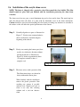
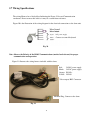
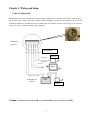
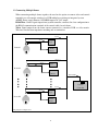
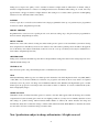
Micro Dome
PTZ Camera
Instruction Manual
English Version
24VAC ~ 60 Hz
Indoor Version
Outdoor Version
Model No: CDC2040MIL
Model No: CDC2040MI &
Model No:
CDC2040MI-1
CDC2040MO &
CDC2040MO-1
Costar Video Systems
2720 Commodore Drive, Suite 150
Carrolton TX 75007
Tel: 972-446-8844
Fax: 972-446-8866
Please read this manual thoroughly before use or installation and keep it handy for future reference.
Rev. M080720
THIS PAGE IS INTENTIONALLY LEFT BLANK
2
WARNINGS AND CAUTIONS
WARNING
TO REDUCE THE RISK OF FIRE OR ELECTRIC SHOCK, DO NOT EXPOSE THIS PRODUCT TO RAIN OR
MOISTURE. DO NOT INSERT ANY METALLIC OBJECTS THROUGH VENTILATION GRILLS OR OPENINGS ON
THE EQUIPMENT.
CAUTION
EXPLANATION OF GRAPHICAL SYMBOLS
The lighting flash with arrowhead symbol, within an equilateral triangle, is intended to alert the user the
presence of non-insulated “dangerous voltage” within the product’s enclosure that maybe of sufficient
magnitude to constitute a risk of electric shock to different persons.
The exclamation point within an equilateral triangle, is intended to alert the user the presence of
important operating and maintenance (servicing) instructions in the literature accompanying this product
PRECAUTIONS:
1. Persons without technical qualifications should not attempt to operate this dome device before reading this manual
thoroughly.
2. Remove any power to the dome before attempting any operations or adjustments inside the dome cover to avoid
potential damage to the mechanism.
3. Inside the dome cover there are precision optical and electrical devices. Heavy pressure, shock and other sudden
adjustments or operations should be avoided. Otherwise, you may cause irreparable damage to the product.
4. Please DO NOT remove or disassemble any internal parts or the video camera. Any such attempt will void the
warranty. There are no serviceable parts inside the dome.
5. All electrical connections to the dome should be made in strict accordance with the attached labels and wiring
instructions in this manual. Failure to do so may damage the dome beyond repair and void the warranty.
6. For outdoor installation especially in high places or poles, it is highly recommended that the proper lightning arrestors
and surge suppressors are installed before the dome is entered into service.
7. Please do not use the product under circumstances where the limits exceed the maximum specified temperature,
humidity or power supply specifications.
3
FCC COMPLIANCE STATEMENT
FCC INFORMATION: THIS EQUIPMENT HAS BEEN TESTED AND FOUND TO COMPLY
WITH THE LIMITS OF A CLASS A DIGITAL DEVICE, PURSUANT TO PART 15 OF THE FCC
RULES. THESE LIMITS ARE DESIGNED TO PROVIDE REASONABLE PROTECTION
AGAINST HARMFUL INTERFERENCE WHEN THE EQUIPMENT IS OPERATED IN A
COMMERCIAL ENVIRONMENT. THIS EQUIPMENT GENERATES, USES, AND CAN
RADIATE RADIO FREQUENCY ENERGY AND IF NOT INSTALLED AND USED IN
ACCORDANCE
WITH
THE
INSTRUCTION
MANUAL,
MAY CAUSE
HARMFUL
INTERFERENCE TO RADIO COMMUNICATIONS. OPERATION OF THIS EQUIPMENT IN A
RESIDENTIAL AREA IS LIKELY TO CAUSE HARMFUL INTERFERENCE IN WHICH CASE
THE USER WILL BE REQUIRED TO CORRECT THE INTERFERENCE AT HIS OWN
EXPENSE.
CAUTION: CHANGES OR MODIFICATIONS NOT EXPRESSLY APPROVED BY THE
PARTY RESPONSIBLE FOR COMPLIANCE COULD VOID THE USER’S AUTHORITY TO
OPERATE THE EQUIPMENT.
THIS CLASS A DIGITAL APPARATUS COMPLIES WITH CANADIAN ICES-003.
CET APPAREUIL NUMERIQUE DE LA CLASSE A EST CONFORME A LA NORME NMB-003
DU CANADA
CE COMPLIANCE STATEMENT
THIS IS A CLASS A PRODUCT, IN A DOMESTIC ENVIRONMENT THIS PRODUCT MAY
CAUSE RADIO INTERFERENCE IN WHICH CASE THE USER MAY BE REQUIRED TO
TAKE ADEQUATE MEASURES.
4
IMPORTANT SAFEGUARDS
1. Read these instructions before attempting installation or operation of dome device.
2. Keep these instructions for future reference.
3. Heed all warnings and adhere to electrical specifications.
4. Follow all instructions.
5. Clean only with non abrasive dry cotton cloth, lint free and approved
acrylic cleaners.
6. Should the lens of the camera become dirty, use special lens cleaning cloth and solution.
7. Do not block any ventilation openings.
8. Install in accordance with manufacturer’s instructions.
9. Use only attachments or accessories specified by the manufacturer.
10. Verify that the surface you are planning to use for attaching the dome can
adequately support the weight of the device and mounting hardware.
11. Protect this devices against lighting storms with proper power supplies.
12. Refer all servicing to qualified service personnel. Servicing is required when the device has
been damaged in any way, when liquid traces are present, the presence of loose objects is
evident, if the device does not function properly, has received severe impact, or has been
dropped accidentally.
13. Indoor dome is for indoor use only and not suitable for outdoor or high humidity locations. Do
not use this product under circumstances exceeding specified temperature and humidity ratings.
14. Avoid pointing the camera directly into the sun or other extremely bright objects for prolonged
period of time avoiding the risk of permanent damages to the imaging sensor.
15. The attached instructions are for use by qualified personnel only. To reduce the risks of electric
shock do not perform any servicing other than contained in the operating instructions unless
you are qualified to do so.
16. During usage, user should abide by all electrical safety standards and adhere to electrical
specifications for the operation of the dome. The control cable for RS485 communications as
well as the video signal cables should be isolated from high voltage equipment and or high
voltage cables.
17. Use supplied or Certified / Listed Class 2, 24 VAC power supply transformer only.
5
1
Chapter 1 – Introduction
Table of Contents
1.1 Performance Characteristics .......................................................................................................................... 7
1.2 Model Numbers ........................................................................................................................................... 8
1.3 Features and Functions .................................................................................................................................. 8
2
Chapter 2 – Installation and configuration
2.1 Package contents............................................................................................................................................ 9
2.2 Camera shroud removal and installation........................................................................................................ 10
2.3 Communication settings................................................................................................................................. 11
2.4 Wall bracket installation................................................................................................................................. 13
2.5 Attaching the dome to the bracket ................................................................................................................. 14
2.6 Installation of the acrylic dome cover............................................................................................................ 15
2.7 Wiring Harness Specifications ....................................................................................................................... 16
3
Chapter 3 – Wiring and Setup
3.1 Basic Configuration ....................................................................................................................................... 17
3.2 Connecting Multiple Domes .......................................................................................................................... 18
4
Chapter 4 – Quick Start Operation Guide
4.1 Connecting power to the dome ...................................................................................................................... 19
4.2 Setting joystick protocol and baud rate. ....................................................................................................... 19
4.3 Start testing .................................................................................................................................................... 19
4.4 Complete the test ........................................................................................................................................... 19
4.5 Direct input Commands for dome operation.................................................................................................. 20
4.6 Camera OSD menu ........................................................................................................................................ 22
5
Chapter 5 – Program and Operation
5.1 Main menu ..................................................................................................................................................... 23
5.2 Tree Menu List............................................................................................................................................... 24
5.2.1 Language Options .................................................................................................................................. 25
5.2.2 Display options ...................................................................................................................................... 25
5.2.3 Control options....................................................................................................................................... 31
5.2.4 Diagnostic Options................................................................................................................................. 35
5.2.5 Camera Options...................................................................................................................................... 36, 41
6
5.2.6 Program Vector Scan.............................................................................................................................. 36
Chapter 6 – Direct Command entry (Short-cuts) & Technical Specifications
6.1
Command reference table....................................................................................................................... 46
7
6.2 Technical Specifications......................................................................................................................... 47
Chapter 7 – Trouble Shooting .............................................................................................................................. 48
8
Chapter 8 – Appendix Glossary........................................................................................................................... 50
6
1. Introduction
The CDC2040 xxx Micro series Low to High Speed domes and a series of compatible keyboard
controllers make up the building blocks for any size video surveillance system. Using multiple
keyboard controllers and multiple high speed dome camera units, one can monitor a variety of
environments from small to very large. Extensive and flexible architecture facilitates remote control
functions for a variety of external switching devices such as multiplexers and DVRs.
1.1 Performance Characteristics
•
Built-in 10x (times) Optical power zoom camera with true day night capability (depending
model, see specifications on page 47).
•
1255 individually addressed units. The dome address is defined using a dip switch with 8
positions (Binary addressing scheme).
•
Integrated multi-protocol selected via Dip Switch settings for Pelco D and Pelco P.
Note: The dome can auto differentiate the protocol of the controller only on power up.
•
Continuous Pan 360 degree rotation (slip ring).
•
90 degree Tilt action plus 2 degree angle adjustment (the view angle can be 90 or 92 degrees).
•
Pan speed in manual operation is variable from 0.1 up to 240 degrees per second.
•
Tilt speed in manual operation is variable from 0.1 to 100 degrees per second.
•
64 or 128 preset positions (depending model). (A preset position is defined as a user definable
setting for precise coordinates, pan, tilt and zoom on all 3 axis).
•
The maximum speed when a preset position is called can reach 300 degrees per second with
positioning accuracy of ±0.1 degree.
•
Compatible with a variety of Camera Modules.
•
Input power supply: 24 VAC – 0.5Amp (indoor or outdoor model.
•
User friendly on screen camera menu interface for ease of installation. (Depends on Model).
•
Environmental protection conforming to IP66 standards (outdoor model).
•
RS-485 (long distance) communications mode.
•
Selectable transmission speed, (i.e. Baud rate). User definable via dip switch settings from
2400bps~9600bps.
7
1.2 Model Numbers
Model No: CDC2040MIL
Model No: CDC2040MI-1
Model No: CDC2040MI
Model No: CDC2040MO-1
Model No: CDC2040MO
Micro Dome Indoor Low Speed Nylon Housing without OSD
Micro Dome Indoor High Speed Aluminum Housing without OSD
Micro Dome Indoor High Speed Aluminum Housing with OSD
Micro Dome Outdoor High Speed Aluminum Housing without OSD
Micro Dome Outdoor High Speed Aluminum Housing with OSD
1.3 Features and Functions
•
Multi-language on screen menu for operation and function settings. (Depends on model).
•
On screen Camera Title. (The camera title is user definable as well as the ability to display or not
the camera coordinates, depending on model).
•
Six user definable vector scans (including scan speed, dwell time, preset and dwell time between
tours).
•
Auto flip function with + 10 degree positioning.
•
Six sectors of user programmable privacy zones (sectional mask). User can mask part of the
camera sectors which differs between different models.
•
Six sectors of user programmable sectional display. User can define and display the name and
position of the camera, which differs between different models of installed cameras.
•
Resume automatic operation after initial self-test of the dome as well as resume automatic
operation when there is no transmission from a keyboard controller. (Dwell time can be set from
1 to 999 seconds).
•
Freeze frame function.
•
Resume operation function. (Dome unit will return to the previous operation after the execution
of an operation using the on screen menu).
•
Intelligent manual scan function.By executing this function in manual pan operation, you can
adjust the manual pan behavior of the dome.
•
Intelligent power off real time memory.Should power fail while the dome was in operation, the
dome will resume its preprogrammed function upon power restore).
•
Zoom and dome speed correlation function. (When the camera is zoomed in close, the dome
speed is reduced to allow for precise operation control).
8
2.0 Installation & Configuration
2.1 Package Contents
The dome carton contains the following:
Description
Qty
High Speed Dome mechanism
1
Camera Module
1
Clear Acrylic dome cover
1
Camera shroud (black)
1
Plastic bag W/ Screws (2xM4*10, 2xM4*3)
1
(2xM4*6, 4xM2*4) + Mini Screwdriver
O-ring + Adapter for wall or ceiling bracket
6 conductor Control/Power/Video harness
1
24VAC transformer 1500 mA
1
Wall bracket
1
Ceiling bracket 4”
1
Instruction manual
1
Figure 1. Illustrates the upper layer of the packing material (top half)
Figure 2. Illustrates the lower layer of the carton (bottom half).
High Speed Dome & Camera
24 VAC, 2 Amp
Transformer
Wall Bracket
Screws + Adapter
+ O ring
Ceiling Adapter
Base
Fig.1
Cable Harness and connectors
Manual and Quality certificate,
placed on top (not illustrated)
9
Ceiling Adapter
Spacer 4”
Fig. 2
2.2 Camera Shroud removal / installation.
Figure 10. Illustrates the camera shroud in position over the camera module
Figure 11. Illustrates the location of the tab for the camera shroud in close position (twist On/Off)
Fig. 10
Fig. 11
The CDC2040 series dome is equipped with a quick release camera liner supported by 3 tabs attached
to a ring affixed to the PTZ mechanism. The liner needs to be removed in order to reach the dip switch
settings of the dome for proper addressing and selection of the communication protocol / baud rate.
Step 1: Restrict the movement of the dome
mechanism and rotate the camera liner
counterclockwise from “close” to “open”
position as illustrated.
Step 2: Remove the camera liner to
gain access to the dip switch
settings located on the
PC-Board underneath the
camera.
Note: Illustrations are for reference purposes only and may vary from actual package contents depending upon
selected installation options at time of order.
10
2.3 Communication Settings
2.3.1 Dip Switch Location.
Before installation and use, the unique address for each dome and the communication protocol including
transmission speed (baud rate) should be set to correspond with the chosen control system. In order to set the
corresponding dip-switches remove the camera liner as previously illustrated and locate the two Dip-Switch
rows (8 & 4) behind the camera module on the main PCB as illustrated.
2.3.2 Setting the address, protocol and baud rate for each dome device.
Note: The illustration shows the two Dip-Switches.
The switch on the left (8 position) is for the dome
address while the switch on the right is for the
protocol and baud rate settings. See Section 2.3.3-4
The Table in the illustration provides the settings
for the two protocols supported, Pelco D and
Pelco P as well as the baud rate settings.
This illustration demonstrates the settings for
Dome Address 1, with Protocol Pelco P at a baud
rate of 4800 setting.
CAUTION: The protocol and baud rate of dome device should match the settings of the controller.
In order for the settings to take effect the dome must be power cycled after each change.
11
2.3.3 Address setting of each dome. To prevent damage, each dome must have a unique address (ID).
On/off switch and
matching numbers
On/Off switch
Example: The sum of switch numbers in the ON position is the
address of the dome device. (Binary Method)
Setting address for dome device
(this figure shows the address of
dome device No 1).
128
64
32
16
1
2
4
8
Dome device range: 1~255.
Calculation example
of dome device address:
2
16
4
2+4+16=22 the dome address is: 22
2.3.4 Addressing Examples 1-15
Address
SW1
SW2
SW3
SW4
SW5
SW6
SW7
SW8
1
ON
OFF
OFF
OFF
OFF
OFF
OFF
OFF
2
OFF
ON
OFF
OFF
OFF
OFF
OFF
OFF
3
ON
ON
OFF
OFF
OFF
OFF
OFF
OFF
4
OFF
OFF
ON
OFF
OFF
OFF
OFF
OFF
5
ON
OFF
ON
OFF
OFF
OFF
OFF
OFF
6
OFF
ON
ON
OFF
OFF
OFF
OFF
OFF
7
ON
ON
ON
OFF
OFF
OFF
OFF
OFF
8
OFF
OFF
OFF
ON
OFF
OFF
OFF
OFF
9
ON
OFF
OFF
ON
OFF
OFF
OFF
OFF
10
OFF
ON
OFF
ON
OFF
OFF
OFF
OFF
11
ON
ON
OFF
ON
OFF
OFF
OFF
OFF
12
OFF
OFF
ON
ON
OFF
OFF
OFF
OFF
13
ON
OFF
ON
ON
OFF
OFF
OFF
OFF
14
OFF
ON
ON
ON
OFF
OFF
OFF
OFF
15
ON
ON
ON
ON
OFF
OFF
OFF
OFF
12
2.4 Wall bracket installation.
Step 1: Feed the supplied wiring harness through the channel inside the wall bracket as
illustrated in Fig. 13. Verify that the 6 pin connector is remaining outside the
opening of the bracket as illustrated in Fig. 14.
Fig. 13
Fig. 14
Step 2: Affix the wall bracket to the wall as illustrated in Figure 15 verifying that the
surface you are attaching to can support the weight of the dome using either expanding
anchors or butterfly fasteners.
Fig. 15
Fig. 16
Note: Different bracket options may be available. Illustrations are for reference purposes only and may vary
from actual package contents depending selected installation options at time of order.
13
Note: It is important that you set the dip switch settings for the dome address,
communication parameters and protocol BEFORE you install the dome in its physical
location of operation.
2.5 Attaching the dome to the bracket
Step 1: Locate the small plastic bag containing the O-ring,
adapter, screws, and small screwdriver as illustrated.
Step 2: Install the O-ring onto the wall bracket as illustrated.
Step 3: Install the adapter onto the top of the dome as
illustrated.
Step 4: Suspend the dome to the bracket using the stainless
hook as illustrated.
Step 5: Connect the end of the wiring harness protruding out
of the bracket to the mating connector on the dome
unit. Observe proper orientation of the connectors as
illustrated.
Step 6: Push the dome into the bracket and align the holes.
Using the supplied screws (with the two rubber
O-rings) secure the dome in place as illustrated.
When finished the dome should look like the illustration on
the right ready to be powered up.
14
2.6 Installation of the acrylic dome cover
NOTE: The dome is shipped with a protective clear film around the clear bubble. This film
should remain in place until you finished with the installation protecting the dome from
scratches.
The dome cover has two parts, a metal aluminum ring and a clear acrylic dome. The metal ring has
male fine threads that will allow it to mate with the aluminum cover of the dome mechanism.
Caution should be exercised when handling the clear dome preventing any abrasions or scratches to
the surface as this will affect the optical performance of the camera.
Step 1: Carefully align the two parts as illustrated in
Figure 17. Slowly rotate counterclockwise
until a small click is felt indicating the
beginning of the threads.
Fig. 17 Align the two parts
Step 2: Slowly start rotating the bottom part (clear
acrylic) in a clockwise direction without
forcing the threads as illustrated in
Figure 18. It takes approximately three
(3) complete rotations to have a
complete seal.
Fig. 18
Rotate clockwise as indicated
Step 3: The dome arrives with a protective film.
The illustrations above are shown for
clarity without the film in place.
When finished with the installation
remove the plastic protective film
avoiding any contact if possible
with the lens. Should you need to
clean it use only lens cleaning
solution and a soft non abrasive
cloth.
Fig. 19 Protection film of acrylic shield
15
2.7 Wiring Specifications
The wiring Harness has a label affixed indicating the Power, Video and Communication
conductors. Do not remove this label as it may be a useful future reference.
Figure 20 is the illustration of the wiring diagram for the electrical connections to the dome unit.
24V power supply
Connect to control keyboard
Fig. 20
Note: Observe the Polarity of the RS485 Communications (marked and relevant) for proper
communication and operation.
Figure 21 illustrates the wiring harness included with the dome.
Red:
Black:
Orange:
Yellow:
24VAC power supply
24VAC power supply
RS485+
RS485-
Video output, BNC Connector
Modular Plug, Connect to the dome
Fig. 21
16
Chapter 3: Wiring and Setup
3.1 Basic Configuration
The illustration below provides the basic electrical wiring configuration for connecting and testing a single dome to a
test monitor and a joystick / keyboard controller. When installing the product for the first times please read the
installation instructions carefully and become familiar with the electrical connections and setup options. Incorrect
wiring may result to permanent damage of the equipment.
6 Pin Header
Connector
Wiring Harness
AC24V (Red)
24VAC
Transformer
AC24V (Black)
Video Out
Monitor
Video GRND
RS485 signal+ (orange)
RS485 signal- (yellow)
Joystick /Keyboard
Controller
12 VDC
Transformer
Caution: Connections to the dome should be performed with the power removed (Power OFF).
17
3.2 Connecting Multiple Domes
When connecting multiple domes together, the user has the option to connect video and control
terminals to a video matrix switcher or a DVR multiplexer creating an integrated system.
AC24V: Power supply Primary 110V/60HZ input to AC 24V output.
RS-485 Bus: Control signal output from joystick controller, connected in a bus configuration to
the RS485 communication terminals of the control cable for each dome.
Video: Signal output from the dome camera connected to a monitor, DVR, or video matrix.
Take into consideration impedance matching and or termination.
RS-485
AC24V
Video
Dome #1
Power
Supply
CCTV
Monitor
RS-485
AC24V
Video
Power
Supply
Dome #2
CCTV
Monitor
RS-485
AC24V
Video
Dome #N
Power
Supply
CCTV
Monitor
Wiring Diagram for multiple Domes
18
RS-485 Bus
Joystick
Controller
4. Quick Start Operation Guide
CAUTION: Do not turn the power ON until you have finished all connections and communication settings).
4.1 Connect the power to the dome.
As soon as the power is turned ON, the dome initiates a self test which includes a rotation of the dome on both axis and
the camera will display a brief menu followed by a live image on the monitor.
Note: During self-testing, it is normal to hear a clicking sound caused by the camera module for about 2~5 seconds of
vertical movement, as a result of the vertical self alignment.
4.2 Joystick controller setting.
Set the protocol, baud rate, and address of the keyboard controller to match the settings on the dome
(For instructions of how to set the keyboard communication settings please refer to keyboard controller manual).
Attention: If the protocol setting of the dome is set to auto detection, the protocol of keyboard controller can be set
arbitrarily. But its baud rate should be set identical with that of the dome device.
4.3 Start testing.
When all of the above settings are completed you can start testing to dome functionality.
1. Direction control test of dome device
2. Zooming control test of camera
Up
Right
Left
Rotate
Zoom in
Zoom out
Down
The operation of the dome and the direction (up,
Zoom control of the camera can be achieved by
down, left and right) of the camera can be
rotating the knob on the joystick or by using TELE
controlled using the joystick of the keyboard
(zoom in) and WIDE (zoon out) functions on the
controller, as illustrated above.
keyboard controller as illustrated above.
Please refer to the next section for demonstration of menu operation and control of dome device.
4.4 Complete the test. (Summary).
If you have achieved control of the dome device as described in section 4.6 above, the system is
basically normal. Do not change the wiring or the applied settings.
If the dome does not respond to the commands or only partial functionality is achieved, verify the
wiring connections (section3.1 and 3.2) and communication parameter settings (sections 2.4, and
2.5) carefully.
19
4.5 Direct Input Commands for Dome Operation
The following preset position addresses are reference to the direct memory location of the dome
controller. They do not correspond to memory preset positions in the keyboard controller or software
applications that support PTZ preset functions. Please consult the manual of the chosen keyboard
controller for correct operation.
Dome preset memory locations: No. 150, 64 ~77 and 102~165total 128 preset positions
Special Function memory preset location: No.5163, No.78101.
The following commands are examples of direct Keyboard Entry from CDC2500MKB Model
Select Dome ID 01:
Save preset position 01:
Recall preset position 01:
Clear preset position 01:
[1] + [ENTER]
[1] + [SHOT] + [ON]
[1] + [SHOT] + [ACK]
[2] + [SHOT] + [OFF]
Keyboard Display: Dome ID:0001
On Screen Display: Stored
Setting Auto Pan scanning between two points: The dome can conduct an auto Pan Scan between
two user preset points. You can operate the Tilt and Zoom controls at the same time without
interrupting the Auto Scan Motion.
Set Start Pan Position:
Set End Pan Position:
[52] + [SHOT] + [ON]
[53] + [SHOT] + [ON]
Setting the Pan speed: user needs to maintain a fixed manual scan speed for more than 3 seconds and
then press [51] + [SHOT] + [ACK] to save this speed as default Pan scan speed.
The dwell time of “starting point” and “ending point” of Pan scan is 2 seconds.
Start Auto Pan:
[52] + [SHOT] + [ACK]
To Stop the Auto Scan move Joystick left or right.
You can resume Auto Scan by pressing again [52] + [SHOT] + [ACK]
Operating a preset tour: Auto point by point scan from preset point 1 to preset 16; (if a certain point
is not set or has been cleared, that point will not observed when “tour scan” is in progress.
The dwell time of each preset point in tour is 4 seconds.
Start Default Preset Tour :
[51] + [SHOT] + [ON]
Please refer to the operation manual of keyboard control for the operation of the other six tour tracks.
To Stop the tour move the joystick of the controller in any direction “Pan” or “Tilt”.
20
Setting the Home position: This means the time duration before the dome positions itself to Preset
No.1 during a period of inactivity. (No keyboard control)
Start this function by pressing:
[100] + [SHOT] + [ACK]
The time interval for returning to Home (preset 1) can be set from 1-2-4-8-10 minutes by pressing:
[95] + [SHOT] + [ACK] = 1 minute
[96] + [SHOT] + [ACK] = 2 minute
[97] + [SHOT] + [ACK] = 4 minute
[98] + [SHOT] + [ACK] = 8 minute
[99] + [SHOT] + [ACK] = 10 minutes
To disable the return to Home Position function press: [100] + [SHOT] + [ON]
Intelligent three-dimension tour scan setting: If a user wishes to monitor an area in continuous Pan
Scan Mode at a specific speed, they only need to maintain the scan speed steady for more than 3
seconds in a continuous pan direction and then press [101] + [SHOT] + [ACK] to continue auto
panning at the same speed.
At the same time, the user can operate the tilt and zoom movements independently.
21
4.7 CAMERA OSD MENU
The following section is specific to the Camera module installed in the CDC2040MIL Dome. The available
options (menus and sub menus) can be accessed directly from the keyboard by entering 57+SHOT+ACK or
57 + PRESET
depending the model and type of the selected keyboard controller.
Main Camera Menu
Color Sub Menu
Position Sub Menu
Iris Sub Menu
APC Sub Menu
Camera Title Sub Menu
Back Light Sub menu
Lens Control Sub Menu
Camera preset Function Sub Menu
Automatic Gain Control Sub Menu
Image Control Sub Menu
22
5. Program and Operation
NOTE: The following instructions apply only to the following models with
OSD (On Screen Display) functions: CDC2040MI and CDC2040MO
5.1 Main menu
The following commands are references to the keyboard controlling the dome. Depending
the make and model of the controller these commands may vary slightly. For reference
purposes the following key labels / acronyms are used:
SHOT = PRESET or PRST - ACK = ENTER - OPEN =Iris open
- CLOSE = Iris Close
1. Press 90+SHOT+ACK on the keyboard to enter the OSD main configuration menu for the
dome.
2. To make a selection move the joystick in the Up or Down direction. The on-screen arrow points
to the selected option. Using the joystick to the Left or Right position you can change the
value of your selection or access the submenu for the selected option.
3. Press the button IRIS OPEN on the keyboard controller to confirm your selection or data entry.
4. Press the button IRIS CLOSE on the keyboard controller to exit menu or return to the previous
menu (one layer up).
HOW TO CONTROL THE ON-SCREEN MENU UTILITY
Action
90 + PRESET
Function
Call the On-screen menu utility
Joystick up or down
Navigate through the menu items.
Joystick left or right
Go into the sub-menu items.
Execute the command(exit)
Change value.
Navigate through the menu items.
IRIS OPEN button
IRIS CLOSE button
Confirm selection.
Exit Menu or
Return to previous menu layer.
23
5.2.
A detailed tree of the OSD menu and sub menus is illustrated below.
5.2.1
5.2.2
5.2.3
5.2.4
5.2.5
5.2.6
Note: Due to space limitations not all screen shots are displayed on this page. Additional information is displayed in
subsequent chapters in this instruction manual.
24
5.2.1. Language Selection
The default is English; Depending on the country of sale different options are available.
Moving the joystick right allows the user to select different language menus.
As an example the screens below illustrate the transition from English menu to Spanish.
5.2.2. Display Options
1. Preset position setup options menu
2. Sector setup options menu
3. On Screen display of X,Y camera position
4. On Screen display of dome information on startup
Press IRIS CLOSE button to return to previous menu
5.2.2.1 PreShot Setup
1. Select a preset position from 1-128
2. Move the PTZ to desired location “Iris Close” to set it
On Screen message displays “Stored” for verification
3. User can recall the selected preset for position validation
4. User can delete the selected preset position
5. User can assign a name to this preset position (14Chr. Max)
6. User can select to display the name for the preset position
Press IRIS CLOSE button to return to previous menu
5.2.2.1.1 Number
The default number is 001. Move the joystick left or right to
position the cursor under the desired numeral and press
IRIS OPEN button to move the cursor on the second numeral
line (0~9). Move the Joystick left or right again under the
desired numeral and press IRIS OPEN button again to select
the desired number (0~9). Press IRIS OPEN button again to
confirm the selection. Press IRIS CLOSE button to finalize
your selection and return to the previous menu level.
25
5.2.2.1.2 Set Preshot
Move the Dome camera to the desired position on all 3 axis
(P,T,Z) and then press IRIS CLOSE button to confirm the
preset position location and return to the previous menu.
The menu will display “Stored” confirming that the position
has been set in the dome memory. If you do not see the
confirmation repeat the process as there may be a latency of
communications depending the wiring method and the
number of devices connected on the RS485 Loop.
5.2.2.1.3 Call Preshot
Based on the displayed/selected preset position on line 1 of
this menu, the dome will respond upon moving the joystick
to the Right position and position itself to the corresponding
coordinates (X,Y, Z) of the selected preset position.
5.2.2.1.4 Delete Preshot
Caution: Are you sure you want to delete this preset?
Press IRIS OPEN button to confirm
Press IRIS CLOSE button to exit and return to the previous
menu level.
5.2.2.1.5 Name _ _ _ _ _ _ _ _
User can edit the name of a preset position. Move the
Joystick Left or Right to select desired character position and
press IRIS OPEN button to display the character selection sub
menu.
Move the joystick Left or Right to select desired character
(0~~9 or A~~Z). Press IRIS OPEN button to confirm selection
and move to the next character of choice.
Press IRIS CLOSE button to exit or return to the previous
menu level when programming is done.
26
5.2.2.1.6 Name Display
Move the joystick Left or Right to select ON or OFF
Based on your selection the name you have entered for this
preset position will be displayed (or not) on the screen when the
PTZ positions itself to this preset position.
Press IRIS CLOSE button to exit and return to the previous
menu level.
5.2.2.2 Sector Setup
On the Display Option menu move the joystick to select the
Sector Setup Menu. Confirm your selection by moving the
Joystick to the right or,
Press IRIS CLOSE button to exit and return to the previous
menu level.
5.2.2.2.1 Number
A sector is defined as a general area bound by user set
coordinates on both axis (X, Y) Example: you can define North
as an area bound by an arc between North-West and North-East.
When the PTZ is pointed in this general area, the name North,
will appear on the screen.
Move the joystick right to select a sector position (1-8)
Press IRIS CLOSE button to return to previous menu
5.2.2.2.2 Name _ _ _ _ _ _ _ _
User can subsequently name the sector by moving the joystick
down to the name field.
Move the Joystick right to display name submenu as
illustrated below.
User can edit the name of a Sector position. Move the
Joystick Left or Right to select desired character position and
press IRIS OPEN button to display the character selection sub
menu.
27
Move the joystick Left or Right to select desired character
(0~~9 or A~~Z). Press IRIS OPEN button to confirm selection
and move to the next character of choice. Press IRIS CLOSE
button to exit or return to the previous menu level when
programming is done.
Press IRIS OPEN button to confirm
Press IRIS CLOSE button to exit and return to the previous
menu level.
5.2.2.2.3 Pan Start POSITION
Move the joystick up or down to the desired selection.
Move the joystick right to make your selection and display the
on screen coordinates. Using the joystick move the pan & tilt to
the desired Pan Start coordinates for the selected sector.
Press IRIS CLOSE button to set the starting pan position
coordinates and return to the previous menu level.
5.2.2.2.4 Pan End POSITION
Move the joystick up or down to the desired selection.
Move the joystick right to make your selection and display the
on screen coordinates. Using the joystick move the pan & tilt to
the desired Pan End coordinates for the selected sector.
Press IRIS CLOSE button to set the ending pan position
coordinates and return to the previous menu level.
28
5.2.2.2.5 Tilt Start POSITION
Move the joystick up or down to the desired selection.
Move the joystick right to make your selection and display the
on screen coordinates. Using the joystick move the pan & tilt to
the desired Tilt Start coordinates for the selected sector.
Press IRIS CLOSE button to set the Tilt Start position
coordinates and return to the previous menu level.
5.2.2.2.6 Tilt End POSITION
Move the joystick up or down to the desired selection.
Move the joystick right to make your selection and display the
on screen coordinates. Using the joystick move the pan & tilt to
the desired Tilt End coordinates for the selected sector.
Press IRIS CLOSE button to set the Tilt End position
coordinates and return to the previous menu level.
5.2.2.2.7 Name Display
Move the joystick up or down to the desired selection.
Move the joystick Left or Right to select ON or OFF
Based on your selection the name you have entered for this
sector will be displayed (or not) on the screen when the PTZ
positions itself within the set of coordinates you have selected.
Press IRIS CLOSE button to exit and return to the previous
menu level.
29
5.2.2.3 Coordinates
Move the joystick up or down to the desired selection.
Move the joystick Left or Right to select ON or OFF
Based on your selection the On-Screen X-Y position
coordinates will be displayed at the bottom of your screen.
Press IRIS CLOSE button to exit and return to the previous
menu level.
5.2.2.4 Start Up Message
Move the joystick up or down to the desired selection.
Move the joystick Left or Right to select ON or OFF
Based on your selection the startup message (see below) will be
displayed on Power Up.
This is particularly useful when you do not know what is the
address or communication setting of this dome.
Press IRIS CLOSE button to exit and return to the previous
menu level.
The Startup message screen displays the following
information:
Manufacturer name
Installed camera module
Protocol of Communication
Dome ID No:
Firmware version
This concludes the Display Options Setup menu.
The following section describes Control options for the PTZ functions.
30
5.2.3. Control Options
Move the joystick up or down to the desired selection.
Move the joystick right to make your selection and display the
Control Options sub-menu or
Press
IRIS CLOSE button to return to previous menu
5.2.3.1 Set Pan & Tilt
Move the joystick up or down to the desired selection.
Move the joystick Left or Right to make selection.
Different options are possible based on the function you
selected including sub- menus with additional options.
Press IRIS CLOSE button to exit and return to the previous
menu level.
5.2.3.1.1 Pan Reverse
Move the joystick up or down to the desired selection.
Move the joystick Left or Right to choose ON or OFF
This allows the user to change the direction the pan motor.
It is useful under certain conditions based on the physical
installation of the PTZ (Example: Upside-Down)
5.2.3.1.2 Tilt Reverse
Move the joystick up or down to the desired selection.
Move the joystick Left or Right to choose ON or OFF
This allows the user to change the direction the tilt motor.
It is useful under certain conditions based on the physical
installation of the PTZ (Example: Upside-Down)
5.2.3.1.3 Tilt Reverse
Move the joystick up or down to the desired selection.
Move the joystick Left or Right to choose ON or OFF
This allows the user to control the horizon of the tilt axis.
It is useful under certain conditions based on the physical
installation of the PTZ (Example: Low Vertical Height)
31
5.2.3.1.4 Tilt Reverse
Move the joystick up or down to the desired selection.
Move the joystick Left or Right to choose ON or OFF
This allows the user to control the standby position of the PTZ.
When turned ON, the PTZ will return to Home Position when it
remains idle for more than 5 minutes.
5.2.3.2 Set Default Function
Move the joystick up or down to the desired selection.
Move the joystick Left or Right to make selection.
Different options are possible based on the function you
selected including sub- menus with additional options.
Press IRIS CLOSE button to exit and return to the previous
menu level.
5.2.3.2.1 Default Function
This defines the behavior of the dome to respond to a preset or a
vector as the default position.
Move the joystick Left or Right to select
P=preset, V= Vector
5.2.3.2.2 Number
The default number is 001. Move the joystick left or right to
position the cursor under the desired numeral and press
IRIS OPEN button to move the cursor on the second numeral
line (0~9). Move the Joystick left or right again under the
desired numeral and press IRIS OPEN button again to select
the desired number (0~9). Press IRIS OPEN button again to
confirm the selection. Press IRIS CLOSE button to finalize
your selection and return to the previous menu level.
32
5.2.3.2.3 Delay
The default number is 120 seconds. This is the time delay
before the PTZ returns to the default position after 120 seconds
of inactivity.
Move the joystick Left or Right to make selection.
Move the joystick left or right to position the cursor under the
desired numeral and press IRIS OPEN button to move the
cursor on the second numeral line (0~9). Move the Joystick left
or right again under the desired numeral and press IRIS OPEN
button again to select the desired number (0~9). Press IRIS
OPEN button again to confirm the selection. Press IRIS
CLOSE button to finalize your selection and return to the
previous menu level.
5.2.3.2.4 Operation
Move the joystick up or down to the desired selection.
Move the joystick Left or Right to make selection.
ON=PTZ will return to default position
OFF= PTZ will remain in last position of operation.
5.2.3.3 Speed Limit
Move the joystick up or down to the desired selection.
Move the joystick Left or Right to turn ON or OFF.
This selection allows the user to control the speed
behavior of the dome.
Press IRIS CLOSE button to exit and return to the previous
menu level.
5.2.3.4 Auto Flip
Move the joystick up or down to the desired selection.
Move the joystick Left or Right to choose ON or OFF
This selection allows the user to control the behavior of the
dome when it reaches to lowest tilt position. The Pan motor will
change direction and reverse the image allowing you to follow
the moving object without screen reversal.
33
5.2.3.5 Auto Focus
Move the joystick up or down to the desired selection.
Move the joystick Left or Right to choose PTZ, OFF or Z
These selections allow the user to control the behavior of the
auto focus mechanism.
PTZ = Auto Focus. The camera adjusts the focus automatically
while monitoring the screen continuously.
OFF = Manual Operation, user must adjust focus manually.
Z = Camera will focus upon operation of the zoom control
5.2.3.6 Auto AE
Move the joystick up or down to the desired selection.
Move the joystick Left or Right to choose PTZ, OFF or Z
These selections allows the user to control the behavior of the
Auto Exposure camera control.
PTZ = Auto Exposure. The camera adjusts the brightness
automatically while monitoring the screen continuously.
OFF = Manual Operation, user must adjust exposure manually.
Z = Camera will adjust upon operation of the zoom control
5.2.3.7 Vector Scan AF
Move the joystick up or down to the desired selection.
Move the joystick Left or Right to choose ON or OFF
This selection allows the user to control the behavior of the
automatic focus during vector scanning operation.
ON= Automatic focus is enabled
OFF= User must adjust the focus manually
5.2.3.8 Vector Scan Still
Move the joystick up or down to the desired selection.
Move the joystick Left or Right to choose ON or OFF
This selection allows the user to control the behavior of the PTZ
during Vector Scan mode.
This concludes the Control Options Setup menu.
The following section describes Diagnostic options for the dome functions.
34
5.2.4 Diagnostics
Move the joystick up or down to the desired selection.
Move the joystick Left or Right to make selection.
Different options are possible based on the function you
selected including sub- menus with additional options.
Press IRIS CLOSE button to exit and return to the previous
menu level.
5.2.4.1 Clear Memory
Move the joystick up or down to the desired selection.
Move the joystick Left or Right to make selection.
This selection allows the user to erase the dome memory from
any user settings including presets, tours and any titles entered.
If you wish to clear the memory press IRIS OPEN button to
confirm your selection or press IRIS CLOSE button to exit
and return to the previous menu.
5.2.4.2 Restore Default Setting
Move the joystick up or down to the desired selection.
Move the joystick Left or Right to make selection.
This selection allows the user to restore factory default
parameters into the memory of the dome.
If you wish to clear the memory press IRIS OPEN button to
confirm your selection or press IRIS CLOSE button to exit
and return to the previous menu.
5.2.4.3 Color System
Move the joystick up or down to the desired selection.
Move the joystick Left or Right to choose NTSC or PAL
selecting the video standard format for the camera operation.
The standard format for North America is NTSC.
5.2.4.4 Scan Camera Reset
Move the joystick up or down to the desired selection.
Move the joystick Left or Right to make selection.
This selection is reserved for future use and it is currently not
applicable. (N/A)
5.2.4.5 Dome Information
35
Move the joystick up or down to the desired selection.
Move the joystick Left or Right to make selection.
This selection allows the user to display the dome information
regarding Dome ID number, selected communication protocol
and baud rate as well as the installed firmware version.
A sample of the default screen is illustrated below.
These options may vary according the dome model and the
installed camera module.
This concludes the Control Options Setup menu.
The following section describes Camera options for the installed module.
NOTE: The Camera options are explained in detail in a separate section of this manual
5.2.5 Camera Options
Move the joystick up or down to the desired selection.
Move the joystick Left or Right to make selection.
Different options are possible based on the function you
selected including sub- menus with additional options.
5.2.6 Program Vector Scan
Move the joystick up or down to the desired selection.
Move the joystick Left or Right to make selection.
Different options are possible based on the function you
selected including sub- menus with additional options.
5.2.6.1 Number
The default number is 1. Move the joystick left or right to select
1 through 6 Vectors (or tours) available. Each tour can be
programmed for up to 16 preset positions with individual speed
and dwell settings for each preset.
Press IRIS CLOSE button to finalize your selection and return
to the previous menu level.
36
5.2.6.2 Program a Vector Scan
Move the joystick up or down to the desired selection.
Move the joystick Left or Right to make your selection.
The submenu displayed below allows the user to select up to 16
preset positions 1- 8 on the first page and 9-16 on the second page
(move joystick down to access the second page)
Under “name” you can select “P” or “V” indicating a preset or a
vector as your selection
Under “num” you can select any of the 128 preset positions
available as you selection.
Under “V” you can select a speed for the PTZ motion 1 - 9
Under “dwell” you can select a time delay from 1 – 99
Move the joystick Left or Right to make selection.
Move the joystick left or right to position the cursor under the
desired numeral and press IRIS OPEN button to move the cursor on
the second numeral line (0~9). Move the Joystick left or right again
under the desired numeral and press IRIS OPEN button again to
select the desired number (0~9). Press IRIS OPEN button again to
confirm the selection. Press IRIS CLOSE button to finalize your
selection and return to the previous menu level.
5.2.6.3 Run a Vector Scan
Move the joystick up or down to the desired selection.
Move the joystick Left or Right to execute the command and run the
selected tour.
Move the joystick in any direction to cancel the tour and display the
menu again.
5.2.6.4 Delete a Vector Scan
Move the joystick up or down to the desired selection.
Move the joystick Left or Right to make your selection.
A confirmation dialog appears confirming your selection.
Press IRIS OPEN button again to confirm the selection. Press IRIS
CLOSE button to finalize your selection and return to the previous
menu level.
This concludes the available selections (menus and sub menus) under the keyboard command
90+SHOT+ACK or 90 + PRESET for the OSD main configuration menu of the dome.
37
5.2.5 Continued from Previous Section:
The following section is specific to the Camera module available options (menus and sub
menus) that can also be accessed directly from the keyboard by entering 57+SHOT+ACK or
57 + PRESET depending the model and type of the selected keyboard controller.
Main Setup
CAM TITLE
WHITE BAL
BACKLIGHT
MOTION DET
FOCUS
SPECIAL
SPECIAL SETUP (Sub Menu)
USER PRESET ON – OFF
ON – OFF
ON -- USER PRESET SETUP (Sub Menu)
ON -CAM TITLE SETUP (Sub Menu)
PRESET NO
NO 1-8
ATW-MANUAL-AWC
PRESET MODE
ON-OFF
ATW MODE (Sub Menu)
ON -- FOCUS SETUP (Sub Menu)
OUTDOOR
MODE
MANUAL-AUTO-ONE PUSH
INDOOR
END
ZOOM TRK
ON-OFF
MANUAL SETUP
(Sub Menu)
ZOOM SPEED
FAST SLOW
RED
1-100
D-ZOOM
ON-OFF
BLUE 1-100
DISP ZOOM MAG
ON OFF
END
EXPOSURE
AWC SET
EXPOSURE SETUP SPECIAL SETUP (Sub Menu)
OFF-LOW-MIDDLE-HIGH
BRIGHTNESS SPECIAL SETUP (Sub Menu)
ON – OFF
IRIS
AUTO – MANUAL
MD SETUP (Sub Menu)
MANUAL
DISP ALARM OFF-ON
IRIS MANUAL SETUP
AREA SEL
AREA 1-2-3-4
AREA MOD
ON-OFF
IRIS VAL
TOP
END
BOTTOM
SHUTTER
A.FLK - _ _ _ - MANUAL
LEFT
MANUAL
RIGHT
SHUTTER MANUAL SETUP
END
SHUTTER VAL 1/60 – 1/30000
END
FOCUS SETUP (Sub Menu)
AGC
NORMAL HIGH OFF
MODE
MANUAL-AUTO-ONE PUSH
SSNR
LOW-MIDDLE-HIGH-OFF
MANUAL (Sub Menu)
SENS-UP OFF - _ _ _
ZOOM/FOCUS POS SETUP
END
TELE-NEAR-WIDE-FAR
AUTO (Sub Menu)
ETC SPECIAL SETUP (Sub Menu)
ZOOM POS SETUP
ETC SETUP
TELE-WIDE
CAM TITLE
ONE PUSH (Sub Menu)
WHITE BAL
ZOOM/FOCUS POS SETUP (Sub Menu)
BACKLIGHT
TELE-NEAR-WIDE-FAR
MOTION DET
ZOOM TRK
ON-OFF
PRIVACY
ZOOM SPEED FAST – SLOW
DAY/NIGHT
D-ZOOM
ON-OFF
H-REV
ON (Sub Menu)
V-REV
D-ZOOM LIMIT SETUP
END
LIMIT X 2-10
END
END
DISP ZOOM MAG
ON-OFF
PRESET SAVE
ZOOM POS INIT
ON-OFF
PRESET CLEAR
ON (Sub Menu)
END
ZOOM INIT POS SETUP X 1-10
END
LENS INIT
END
EXPOSURE
EXPOSURE SETUP (Sub Menu)
BRIGHTNESS
IRIS
AUTO – MANUAL
MANUAL
IRIS MANUAL SETUP
IRIS VAL
END
SHUTTER
A.FLK - _ _ _ - MANUAL
MANUAL
SHUTTER MANUAL SETUP
SHUTTER VAL 1/60 – 1/30000
END
AGC
NORMAL HIGH OFF
SSNR LOW MIDDLE HIGH OFF
SENS-UP
OFF - _ _ _
END
38
The following section is specific to the Special Setup Sub Menu for the
SAMSUNG Camera module.
SPECIAL SETUP
USER PRESET
ON – OFF
ON – USER PRESET SETUP
PRESET NO. 1-8
PRESET MODE
ON-OFF
ON- USER PRESET MODE SETUP
FOCUS - FOCUS SETUP
MODE
AUTO – ONE PUSH – MANUAL
AUTO – ZOOM POS SETUP
ONE PUSH – ZOOM/FOCUS POS SETUP
MANUAL – ZOOM/FOCUS POS SETUP
ZOOM TRK
ON - OFF
ZOOM SPEED FAST - SLOW
D-ZOOM
ON – OFF
ON – D-ZOOM LIMIT SETUP
LIMIT
X 2-10
END
DISP ZOOM MAG
ON-OFF
END
EXPOSURE - EXPOSURE SETUP
BRIGHTNESS
1-100
IRIS
AUTO – MANUAL
MANUAL - IRIS MANUAL SETUP
IRIS VAL 1-100
END
SHUTTER
A-FLK - _ _ _ - MANUAL
MANUAL - SHUTTER MANUAL SETUP
SHUTTER VALUE 1/60 – 1/120000 – FIX 2X - 128X
AGC HIGH – NORMAL - OFF
SSNR
LOW – MIDDLE – HIGH -OFF
SENS-UP
OFF - _ _ _
END
ETC
ETC SETUP
CAM TITLE
ON-OFF
ON – CAM TITLE SETUP
WHITE BALANCE
ATW - MANUAL - AWC-SET
ATW - WHITE BAL MODE
ATW MODE
OUTDOOR – INDOOR
END
MANUAL
WHITE BAL MANUAL SETUP
RED
1-100
BLUE
1-100
END
BACKLIGHT
OFF-LOW-MIDDLE-HIGH
MOTION DET
ON – OFF
ON - MD-SETUP
DISP ALARM
ON - OFF
AREA SEL
AREA 1-4
AREA MODE
ON - OFF
TOP
1-100
BOTTOM
1-100
LEFT
1-100
RIGHT
1-100
END
SPECIAL SETUP (Cont’d on next page)
39
SPECIAL SETUP (Cont’d)
PRIVACY
ON
END
PRESET SAVE
PRESET CLEAR
END
PRIVACY
ON-OFF
ON – PRIVACY SETUP
GROUP SEL
AREA SEL
AREA MODE
MASK TONE
TOP
BOTTOM
LEFT
RIGHT
END
ON –OFF
USER PRESET PRIVACY SETUP
AREA SEL 1-4
AREA MODE
ON -OFF
MASK TONE
1-100
TOP
1-200
BOTTOM
1-200
LEFT
1-200
RIGHT
1-200
END
DAY/NIGHT
H-REV
V-REV
END
GROUP 1-8
1-4
ON -OFF
1-100
1-200
1-200
1-200
1-200
DAY/NIGHT AUTO 1-2 / COLOR – B/W
SYNC
INT - EXT
COMM A DJ
COMMUNICATION SETUP
CAM ID
1-100
DISP CAM ID
ON – OFF
BAUD RATE
38400
UART MODE
8-N-1
RET PKT
ENABLE-DISABLE
END
IMAGE ADJ
IMAGE SETUP
FREEZE
OFF-ON
H-REV
OFF-ON
V-REV
OFF-ON
SHARPNESS
ON-OFF
ON – SHARPNESS LEVEL
LEVEL 1-50
END
COLOR GAIN
1-100
END
END
RESET
EXIT
40
AUTO 1-2 / COLOR – B/W
ON - OFF
ON - OFF
5.2.5 Camera Options menu
Main Camera menu.
Move the joystick up or down to the desired selection.
Move the joystick Left or Right to make selection.
Different options are possible based on the function you
selected including sub- menus with additional options.
5.2.5.1 CAM TITLE
The camera title options can be turned On or OFF. In the ON
position it allows the user to select a title for the camera as well
as select the position on the screen where the title will be
displayed.
Press IRIS CLOSE button to finalize your selection and return
to the previous menu level.
5.2.5.1.1 CAMERA TITLE SETUP
Move the joystick up or down to the desired selection.
Move the joystick Left or Right to select desired character
(0~9 or A~Z). Press IRIS OPEN button to confirm selection
and move to the next character of choice.
Move the cursor to Clear to delete an entry, End to finish then
Press IRIS CLOSE button to exit or return to the previous
menu level when programming is done.
5.2.5.2 WHITE BALANCE
The White Balance function corrects the abnormal white color
into the normal white color under any color temperature.
The User can select from ATW , Manual or AWC settings.
ATW: Balances the color automatically depending on the source
of light from 1,800 – 10,500 K color temperature.
ATW-OUTDOOR:
ATW-INDOOR:
41
Use this mode under broad color temperature
Use this mode under limited color temperature
MANUAL: Fine tuning is possible trough this manual control
mode. Select the color temperature and increase or decrease the
Red and Blue values to shift the color of the object.
AWC: Set up the lighting to the objects and correct the color
temperature to that of a white object. Camera will work under
the selected parameters. ). Press IRIS OPEN button to set the
AWC. If the conditions change adjust and set the AWC again.
Move the joystick up or down to the desired selection.
Press IRIS CLOSE button to exit or return to the previous
menu level when programming is done.
5.2.5.3 BACKLIGHT
Unlike other cameras, Samsung unique DSP offers a clear
image of the subject even with bright backlight. Move the
joystick Left or Right to choose.
There are several settings available:
HIGH:
Gain increased from 6dB up to 34dB
MIDDLE:
Gain increased from 6dB up to 30dB
LOW:
Gain increased from 6dB up to 18dB
OFF:
BLC function is disabled
5.2.5.4 MOTION DETECTION
The camera is equipped with a motion detection feature.
This feature can be turned ON or OFF. In addition there
are a total of 4 detection Areas that can be turned ON or OFF
individually under Area Mode.
Move the joystick up or down to the desired selection.
5.2.5.4.1 MOTION DETECTION SETUP
The position of the detection area can be adjusted using
directional controls as illustrated. Move the joystick up or down
to the desired selection.
Move the joystick Left or Right to change the position.
Move the joystick to the END selection
Press IRIS CLOSE button to exit or return to the previous
menu level when programming is done.
42
5.2.5.5 FOCUS
In this section you can set the focus mode. Available options are:
AUTO: The camera adjusts the focus automatically while
monitoring the screen continuously in the auto mode. In this
mode the zoom key operation is not recognized as the input of
the focus key.
MANUAL: The user can adjust the focus manually
ONE PUSH: Only if the camera is not moving, it turns into the
manual mode. Same controls as manual
5.2.5.5.1 FOCUS SETUP
ZOOM TRACK: When it is turned ON the focus function is
executed when the zoom function is ON. SPEED-FAST will
speed up the ZOOM, Slow has the opposite effect.
D-ZOOM: Magnification of the Digital Zoom can be selected
from OFF-2X-10X.
Additional options are available such initial position and
magnification including Lens Initialization.
NOTE: It is recommended that you set digital zoom before
setting preset positions. As magnification increases, picture
quality decreases.
5.2.5.6 EXPOSURE
Camera Exposure can be controlled.
Brightness: The brightness of the screen can be adjusted
Iris: Auto or manual mode can be selected
Auto: The image signal can be adjusted relevant to the
amount of available light.
Manual: User can adjust the level
Shutter: Electronic shutter is enabled. The shutter speed is
controlled automatically according to screen brightness.
AFLK: Use this mode when the screen flickers because of
inconsistent frequency of surrounding lights.
5.2.5.6.1 EXPOSURE SETUP
Manual: Shutter speed can be adjusted manually from 1/60 to
1/120000 of a second
SENS UP function can be operated manually from x2-x128
Additional options available:
Move the joystick to the END selection
Press IRIS CLOSE button to exit or return to the previous
43
menu level when programming is done.
5.2.5.7 SPECIAL
Under the special menu a plethora of options are available.
We recommend that only experienced users with specific needs
attempt to configure these options.
For the majority of applications no additional settings are
required from what has been described in the previous sections
of this manual.
Move the joystick up or down to the desired selection.
Move the joystick Left or Right to choose.
5.2.5.7.1 SPECIAL SETUP
Under USER PRESET the use can select a variety of options
related to the specific behavior of the camera regarding Focus,
Exposure, White Balance and others features for specific preset
settings, There are a total of 8 positions that are user
configurable in great detail.
Move the joystick up or down to preset save to save your
selection. Move the joystick to preset clear if you wish to delete
the desired selection.
Move the joystick to the END selection
Press IRIS CLOSE button to exit or return to the previous
menu level when programming is done.
5.2.5.7.1.1 COMM ADJUST
The communication parameters of the camera are factory preset
and do not require any user configurations.
These options are available only for specific needs and for
experienced users.
Move the joystick to the END selection
Press IRIS CLOSE button to exit or return to the previous
menu level when programming is done.
5.2.5.7.1.2 IMAGE ADJUST
For specific placements of the Dome unit such as upside down
or specific circumstances, the user has the ability to adjust the
image such as Horizontal and Vertical flip, modify the
Sharpness, and color gain.
Move the joystick to the END selection
Press IRIS CLOSE button to exit or return to the previous
menu level when programming is done.
44
5.2.5.8 RESET
As a last measure, and if things get complicated, you can reset
the camera to original factory settings.
Move the joystick up or down to the desired selection.
Press IRIS CLOSE button to reset the camera.
The screen will turn black momentarily and the camera will be
reset to original factory parameters.
5.2.5.9 EXIT
When you have finished all your selections and programming
Move the joystick to the EXIT selection to Save your settings
Press IRIS CLOSE button to exit the OSD menu.
45
6. Direct command entry (Short-cuts)
6.1 Keyboard direct entry command reference table
Number
Definition of Keyboard Operation
Control Object
of preset
Call preset position
Save preset position
position
[xx]+[SHOT]+[ACK]
[xx]+[SHOT]+[ON]
51
Save line-scanning speed
52
Pan-Tilt Control
53
55
Background
Enable system default guard
tour
Enable Auto Pan scanning
Set Start Pan Position
System hold
Set End Pan Position
On
Off
On
Off
Light
Compensation
58
Digital Zoom *
59
Focus
Auto
Manual
60
Iris
Auto
Manual
100
Home position
Enable
Disable
1 minute
95
96
Setting the Dwell time interval
2 minutes
97
for the return to Home position
4 minutes
function
8 minutes
98
10 minutes
99
101
Intelligent manual horizontal
ON
continuous scanning
46
6.2 Technical Specifications
Note: Technical specifications may change without prior notice depending on availability of components from
various suppliers and or camera manufacturers.
47
7. Trouble Shooting Problem
Possible Reason
Description
After power is
1
applied, there is no
motion (self test)
and no video image.
2
Cable harness is improperly
Verify that the orientation of the
connected or no AC power
connector and the power supply input
Power PCB inside the dome is
faulted.
Slip ring power wires
disconnected or damaged
Change the power PCB
Verify connector or Change slip ring
Change main control board
After power on, the
OSD Character function is turned
Turn On the OSD display according to
dome device
Off
the instructions in the manual
initiates self test but
no video image or
displayed
After self-test of the
Incorrect Video connection
between camera and control board
or cable harness is damaged
Replace the FFC ribbon cable (spare
supplied) or the camera module
Incorrect command sequence
Enter
90 + SHOT + ACK to display
Fault of OSD control board
Replace OSD board
dome device, OSD
menu is not
Interference caused by external
electronic signals (noise) or the
Distorted Characters
or video image
camera video format is set
incorrectly (NTSC/PAL)
Internal System Error
5
After power On, no
Obstruction of the motor controls
self-test and motor
or incorrect cable connection, or
is locked
temperature below freezing point
Cannot stop pan
6
rotation (rotate and
stop alternatively)
Please follow the supplied
basic system wiring
operation of dome device.
Video will be displayed on the
monitor automatically after 45
seconds from power On
After self-test, the menu can
be displayed only when there
displayed
4
Remarks
instructions to assure proper
Fault of main control board
on screen characters
3
Troubleshooting
is Video image on the monitor
Ground the dome device or identify
and reduce the external interference
(electric motors, HF, high power
You should use properly
fluorescent lamps) or reposition the
shielded video cables.
camera to a different location
Power cycle the dome.
Verify that there are no obstructions
and that the cable is connected
Follow installation
correctly. If this does not solve the
instructions
issue return the unit for service.
OSD board is not properly
Secure OSD board against the main
connected with main control
control board. If the problem still
Rotational tab should be
board.
exists, then replace the OSD board.
aligned in the center of the
Pan interrupt switch is not
Adjust the tab to be aligned with the
photoelectric switch (slot) for
properly aligned or photoelectric
photo electric switch or replace the
proper operation.
switch is broken
switch assembly.
48
Trouble Shooting (Cont’d)
Problem
Description
Possible Reason
Following normal
7
operation, dome
The system could not verify the
will rotate one
start position and initiates a self
revolution while
calibration.
If this happens frequently,
This is a normal self calibration event.
verify the tab alignment
No action required.
with the photoelectric
switch
being controlled
Vertical range is not
8
within 90 2 degree
with large deviation
Self-test is normal,
9
but cannot control
dome
Fault occurs when the dome
device is in tilt movement. It may
be caused by obstruction of
camera which leads to early tilt
movement
Wrong communication settings
Improper connection of control
cable (polarity)
Maximum Communication cable
run is exceeded
10
11
12
Intermittent control
of dome device
Intermittent or incorrect
connections
Check and adjust the mechanical
installation and remove any
obstructions from the camera vertical
platform.
Set the correct protocol, baud rate and
address of dome device
Verify the polarity of the RS485
connection as per the instruction
Verify the wiring
RS-485 protective discharge
Replace RS485 protective discharge
arresters are damaged
arresters (qualified service only)
fails
interference
Dome operates by
No transmission auto “call back”
itself occasionally
function is set to the dome device
instructions
Add amplification circuit for RS485
Replace the slip ring
System failure caused by noise
Follow installation
manual
Slip ring is damaged
Call out function
Remarks
Troubleshooting
This situation may occur
following intense electric
storms or severe lightning.
Restart the dome device
Verify this setting
One dome works
13
well while other do
Incorrect communication settings
Verify the communication setting and
Follow installation
not under identical
or wiring
wiring again
instructions
operation
49
Appendix — Glossary
AREAS
Programmed start and end points of the dome'
s field of view around its pan axis.
Each area is a part of a circular viewing area that extends around the dome. These areas can be different sizes.
AUTOMATIC GAIN CONTROL (AGC)
Allows for the amplification of the video signal in scenes with minimal ambient light. Many low-light scenes result in
picture noise. As gain is increased, the picture noise is also amplified. When AGC is enabled, the value of the gain setting is
based on feedback from the camera. When AGC is disabled, the camera uses the value set for the manual gain setting. The
trade-off between picture level and noise may be adjusted when AGC is disabled.
ON-SCREEN MENU
The text overlay menu system used for setting dome features. The utility is accessed using a
keystroke combination. The utility provides settings for camera functions, zoom, alarms, text
display, and password protection. (Dependant upon model).
FLIP
Allows the dome to automatically turn 180 degrees when the camera tilts to its lower limit and stays in that position for a
brief delay. When the dome flips (rotates), the camera starts moving upward as long as the tilt control is kept in the down
position. Once the control is released, the tilt control returns to its normal operational mode. The flip feature is useful when
you need to track someone who walks directly beneath the dome and continues on the other side.
IR MODE
A feature of the camera that permits manual or automatic switching between color and IR
(black-and-white) operation. When IR mode is active, clearer images may be obtained under
low-light conditions. (Dependant upon model).
LINE LOCK
Allows you to phase lock the video with the AC power line. When line lock is enabled, it prevents vertical video rolling
when switching multiple cameras to a single monitor. If text appears slightly tinted on color monitors, disabling the line
lock may prevent this problem. (Dependant upon model).
NAME INFORMATION
Relates to the display the dome name, the area where the dome is pointing, the name of the preset or pattern that is running,
and alarm names. The display of each type of name setting can be enabled or disabled. When the display of camera or area
title (name) is enabled, the information appears on the screen continuously. Preset, tour and pattern titles (names) appear
only while they are active. (Dependant upon model).
LOW SHUTTER
50
Setting used to improve the quality of video obtained in extreme low-light situations. When the Low Shutter setting is
enabled, low-light information is collected over multiple fields based on the Shutter Limit setting. As a result, video may
appear blurred or choppy in extreme low-light situations. This setting does not effect camera operation in normal lighting
situations. See also Automatic Gain Control (AGC).
PATTERN
A series of pan, tilt, zoom and focus movements from a single programmable dome. Up to 6 patterns may be programmed
for the dome camera. (Dependant upon model).
PRESET - PRESHOT
Programmed video scene, based on a specific pan, tilt, zoom, and focus settings. Up to 128 presets may be programmed for
the dome camera. (Dependant upon model).
PRIVACY ZONES
Masked areas of the dome camera'
s viewing area. These masks prevent operators of the surveillance system from viewing
these designated zones. The Privacy Zones move in relation to the dome camera’s pan/tilt position. In addition, the apparent
size of the Privacy Zone adjusts automatically as the lens zooms in or out. Up to 6 Privacy Zones may be established for a
dome camera. (Dependant upon model).
SHUTTER LIMIT
Setting used to define the maximum exposure time for the Open Shutter setting. The values for the setting range from 1/2 to
1/60. The default setting is 1/4.
VECTOR SCAN
Move from start point to end point including tilt and zoom simultaneously and linearly.
WDR
Wide Dynamic Range Technology uses two shutter speeds in alternative video fields-high and normal- every 60th (NTSC)
or 50th (PAL) of a second and combines two fields into one progressive scan frame. It allows every detail to be captured
accurately even if one portion of an image is more illuminated than the other. Whether at the high shutter speed or normal
shutter speed, the progressive scan CCD provides a horizontal resolution of 470 lines. As a result, combined fields yield a
frame of high-quality images.
WHITE BALANCE
Adjustments in the color hue(red and blue) gains for a camera so that true white appears white in the image. It is normally
compensated for by the automatic gain control. In some lighting conditions, you may need to manually adjust the red and
blue settings for optimal viewing. When Automatic White Balance is enabled, the camera measures the image and
automatically adjusts the red and blue settings to balance white. When Automatic White Balance is disabled, the camera
uses the values set for the red and blue settings to balance white.
Note: Specifications subject to change without notice. All rights reserved.
51
Printed in the USA
Rev. M0807415
52