1
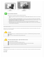
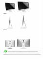
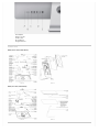
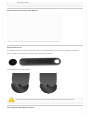
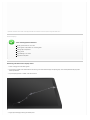
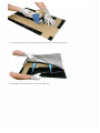
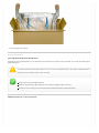
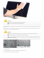
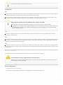
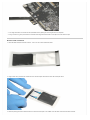
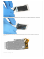
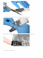
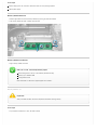
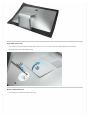
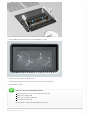
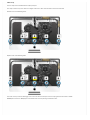
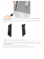
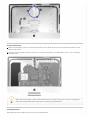
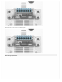
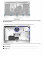
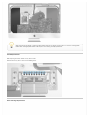
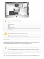
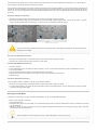
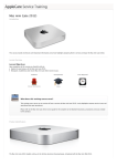
iMac (Late 2012)
Introduction
This course provides technicians with important information and service highlights preparing them to:
Successfully pass the iMac (Late 2012) Qualification Exam
Service and repair the iMac (21.5-inch, Late 2012) and iMac (27-inch, Late 2012)
Lesson Overview
Lesson Objectives
Upon completion of this course you should be able to:
Explain the features of the iMac (21.5-inch, Late 2012) and iMac (27-inch, Late 2012).
Exercise technician safety precautions.
Recognize, troubleshoot and resolve iMac (Late 2012) service issues.
Complete and successfully pass the iMac (Late 2012) Qualification Exam.
Audience
Prerequisites
Time Required
Service Technicians
None
45 Minutes
What does this training course cover?
This training course serves as an overview of how to service the iMac (21.5-inch, Late 2012) and iMac (27-inch, Late 2012). It only
highlights common service issues and specialized take apart procedures.
Please refer to the iMac (21.5-inch, Late 2012) and iMac (27-inch, Late 2012) service guide for the complete set of detailed
instructions, procedures and issues related to this product.
Technician Qualification
IMPORTANT
Only qualified technicians may perform repairs on the iMac (21.5-inch, Late 2012) and iMac (27-inch, Late 2012).
Technician Qualification Process
1. Complete this course.
2. Take the iMac (Late 2012) service qualification exam.
Note: You must score 90% or higher in the Technician Safety section of the exam to pass. If you score lower than 90% in this
section, you will fail the whole exam regardless of your performance in other sections.
For more information about the iMac (Late 2012) service qualification exam, please refer to GSX.
Electric Shock Precautions
High Voltage Warning
Never remove or install any physical components while the computer is plugged in to an electrical outlet.
When plugged in, the power supply and logic board are energized, even when the computer is powered off.
Unplug computer and, when possible, allow sufficient time for the power supply and logic board to self-discharge before
removing display panel.
DO NOT touch the logic board or power supply while the computer is plugged in, or before sufficient time has passed to
discharge stored voltage to a safe level after being unplugged.
Wait 2 minutes for self-discharge
After unplugging the computer from the electrical outlet, wait two minutes before removing display panel, disconnecting modules
or substituting cables and components.
This will allow the power supply and logic board time to discharge.
Power Supply and Logic Board Locations
Power Supply: 21.5-inch
Power Supply: 27-inch
Logic Board: 21.5-inch
Logic Board: 27-inch
Electrical Safety Precautions
Before working on a computer with exposed, potentially energized parts:
1. Remove rings, watches, necklaces, metal-rimmed eyewear, and other metallic articles which increase your risk of electric
shock.
2. Do not wear a cell phone or other signaling device, as these may cause a dangerous startle reflex during energized work.
3. If the iMac needs to be plugged in for LED checks or similar troubleshooting, do NOT wear an ESD wrist strap. Wearing
ESD grounding systems increases your risk of electric shock.
4. Remain alert, focused on the work being performed, and aware of the proximity of grounded objects to your body.
5. Use the plastic black stick or other non-metal extension tool as needed to connect or disconnect cables, to keep fingers
away from potentially energized parts.
Glass Safety Precautions
The iMac (21.5-inch, Late 2012) and iMac (27-inch, Late 2012) has a glass display panel that attaches to the front of the computer, which must be
removed to access internal components.
Important
The display panel's glass is not tempered and will break into sharp pieces if mishandled. Removing the display panel requires
special tools.
Safety Glasses are recommended when removing the display panel.
If for some unforeseen reason, a glass shard enters the eye:
Seek medical attention immediately!
Do not rub your eye if you feel you have something in your eye.
Do not use an eye wash. An eye wash can push or move the shard of glass and cause more damage.
Keep eye closed or even loosely patch the eye to keep eye from moving.
Product Identification
The iMac (21.5-inch, Late 2012) and iMac (27-inch, Late 2012) have an all-aluminum enclosure. The glass front extends all the way to the top, left
and right edges.
Front View
iMac (21.5-inch, Late 2012)
iMac (27-inch, Late 2012)
iMac (21.5-inch, Late 2012)
iMac (27-inch, Late 2012)
iMac (21.5-inch, Late 2012)
iMac (27-inch, Late 2012)
Side View
Rear View
The iMac (Late 2012) models are most easily distinguished by its distinctive shape and SDXC card slot on the rear housing.
Tech Specs
iMac (21.5-inch, Late 2012)
Display
21.5-inch (diagonal) LED-backlit display with IPS technology; 1920-by-1080 resolution with support for millions of colors
Processor
2.7GHz quad-core Intel Core i5 processor (Turbo Boost up to 3.2GHz) with 6MB L3 cache
2.9GHz quad-core Intel Core i5 processor (Turbo Boost up to 3.6GHz) with 6MB L3 cache
3.1GHz quad-core Intel Core i7 (Turbo Boost up to 3.9GHz) (CTO)
Memory
8GB (two 4GB) of 1600MHz DDR3 memory (Configurable to 16GB)
Graphics and video support
NVIDIA GeForce GT 640M graphics processor with 512MB of GDDR5 memory
NVIDIA GeForce GT 650M graphics processor with 512MB of GDDR5 memory
Storage Options
1TB (5400-rpm) hard drive
1TB Fusion Drive
iMac (27-inch, Late 2012)
Display
27-inch (diagonal) LED-backlit display with IPS technology; 2560-by-1440 resolution with support for millions of colors
Processor
2.9GHz quad-core Intel Core i5 processor (Turbo Boost up to 3.6GHz) with 6MB L3 cache
3.2GHz quad-core Intel Core i5 processor (Turbo Boost up to 3.6GHz) with 6MB L3 cache
3.4GHz quad-core Intel Core i7 (Turbo Boost up to 3.9GHz) (CTO)
Memory
8GB (two 4GB) of 1600MHz DDR3 memory; four user-accessible SO-DIMM slots (configurable to 16GB or 32GB)
Graphics and video support
NVIDIA GeForce GTX 660M graphics processor with 512MB of GDDR5 memory
NVIDIA GeForce GTX 675MX graphics processor with 1GB of GDDR5 memory (configurable to NVIDIA GeForce GTX 680MX with 2GB of GDDR5
memory)
Storage Options
1TB (7200-rpm) hard drive (configurable to 3TB hard drive)
1TB or 3TB Fusion Drive
768GB of flash storage
Connections and Expansion
A: Headphone
B: SDXC card slot
C: USB 3 ports
D: Thunderbolt
E: Gigabit Ethernet
Exploded Views
iMac (21.5-inch, Late 2012)
View #1
View #2
iMac (27-inch, Late 2012)
View #1
View #2
Service Tools
The following tools are required to service an iMac (Late 2012):
ESD-safe workstation, including an ESD mat and wrist or heel strap
ESD bags (to store ESD-sensitive parts while removed from computer)
Kit, Starter, LCD Display Panel, 076-1416
Kit, LCD, Service Refill, iMac (21.5-inch, Late 2012), 076-1422
Kit, LCD, Service Refill, iMac (27-inch, Late 2012), 076-1419
Service wedge, iMac (part of starter kit, 076-1416)
Magnetized Torx T25, T10, T8, T6, T5, T4 screwdrivers
Phillips #00 screwdriver
Black stick (nylon probe, Apple part #922-5065)
or other non-conductive nylon or plastic flat-blade tool
Thunderbolt and USB cables for logic board reassembly
Earphones for audio cable reassembly
Thermal material, used to adhere wireless card to logic board, 076-1425
(A twinpak is included with each replacement wireless card or logic board)
Kapton tape
IPA wipes, 95% or higher isopropyl alcohol
Magnifying glass, for reading serial number etched on bottom of stand
Digital volt meter (for troubleshooting)
Soft, clean towel or cloth (to protect display and removed parts from scratches)
Required Special Tools and Supplies for Display Panel
The display on iMac (Late 2012) is secured to the rear enclosure using adhesive strips. When a repair requires the removal of the display panel, these
strips must be cut and replaced. The procedure requires these tools:
Handle, display removal
Display removal wheel
tool
Very High Bond (VHB)
Stand Locking Wedge
adhesive strips
Use of these tools will be covered in greater detail in the Display Removal and Display Replacement section of this course.
Starter Kit (076-1416)
When a repair requires the removal of the display, order a starter kit. It includes:
Handle, Display Removal Tool, iMac (qty 1)
Display removal wheel (qty 8)
Very High Bond (VHB) adhesive strip 6-piece set for iMac (27-inch, Late 2012) (qty 4 sets)
Very High Bond (VHB) adhesive strip 5-piece set for iMac (21.5-inch, Late 2012) (qty 4 sets)
Service, Stand Locking Wedge, iMac (Late 2012)
Refill Kits
Order a refill kit to replenish the consumable parts of the starter kit:
076-1422 Kit, LCD, Service Refill, iMac (21.5-inch, Late 2012)
Very High Bond, VHB, 5-piece set, 20-pack
Display removal wheel (qty 20)
Handle, display removal tool, iMac (qty 1)
076-1419 Kit, LCD, Service Refill, iMac (27-inch, Late 2012)
Very High Bond, VHB, 6-piece set, 20-pack, 076-1419, iMac (27-inch) (qty 20)
Display removal wheel (qty 20)
Handle, display removal tool, iMac (qty 1)
Additional Tools and Supplies
Needed to remove, handle and clean the display panel:
922-9468 – ESD bags, 24”x30”, Pkg of 5. To prevent buildup of static charges which may attract dust particles, store the display
panel in an ESD bag when removed from the unit.
922-8258 – ESD bags that will accommodate a 27” display, Pkg of 5
922-8259 – Microfoam bag to store display panel, Pkg of 5
922-8261 – Sticky silicone roller (6-inch) to adhere VHB strips to the display panel
922-8262 – Sticky sheet pads (Clean roller or pick up shards of broken glass)
922-8263 – Polishing cloths, anti-static, optical-grade micro-terry, Pkg of 5
IPA wipes, 95% or higher isopropyl
Software Tools
The following software programs are required for troubleshooting the iMac (21.5-inch, Late 2012) and iMac (27-inch, Late 2012):
1. Apple Service Toolkit (AST): version 1.4.5 or higher
AST provides a selection of tools that provide a quick check of the general components of Intel-based Mac hardware. Typically used to triage and
verify repairs of Mac computers.
2. Apple Service Diagnostic (ASD): version 3S151
ASD can determine if any of the thermal sensors are malfunctioning. When sensors fail, replace the corresponding part.
3. Apple Hardware Test (AHT)
iMac (21.5-inch, Late 2012): Version 3A229
iMac (27-inch, Late 2012): Version 3A234
AHT contains a suite of diagnostics that will test the hardware of your computer. It's a great way to rule out a hardware issue.
4. Mac Resource Inspector (MRI)
MRI is a troubleshooting tool that reveals system errors and reports sensor readings that help identify parts that need replacement.
Before You Begin
Software and Firmware Update
Before you begin troubleshooting, ensure the correct version of OS X is installed. Use Software Update or the Mac App Store to
check for and apply the latest software and firmware updates.
Computers sometimes exhibit symptoms that indicate the wrong version of OS X system software or outdated firmware version is
installed.
Refer to Apple Support article HT1159 to make sure system build is correct for this computer model.
ESD Reminder
Follow ESD precautions when the display panel is removed.
Take Apart Tips
Review the Electric Shock and Glass Safety precautions found in the beginning of this course.
Follow all cleaning and handling instructions to prevent damaging display panel or LCD panel.
Never place display panel onto a work surface where it may collect dust and other contaminants. Always place it into a protective
microfoam bag.
The chin strap must be removed for the majority of repairs. If a component reaches below the chin, the chinstrap must be
removed before that component can be removed.
Handling the logic board incorrectly could flex the board and damage chips and circuits. Always handle the logic board by its
edges. Never handle the board by heat sink.
When replacing logic board or rear housing, plug in one USB cable and two Thunderbolt cables while tightening screws.
Do not attempt to remove the wireless card without taking out the logic board.
Fusion Drive
Fusion Drive is a breakthrough storage option that combines the high storage capacity of a traditional hard drive and the high performance of flash
based storage (module or solid-state drive).
A traditional hard drive and flash storage are fused together via Core Storage in OS X so you see one single volume.
Fusion Drive automatically and dynamically moves frequently used files to flash for quicker access. It makes disk-intensive tasks faster and more
efficient. A Fusion Drive allows the iMac to boot up to 2x faster and import photos up to 3.6x faster.
Fusion Drive Availability
Fusion Drive is an Apple Online Store configurable option.
iMac (21.5-inch, Late 2012): 1TB Fusion Drive
iMac (27-inch, Late 2012): 1TB or 3TB Fusion Drive
More Information
Fusion Drive service training course (found in GSX)
Apple Support article HT5446
Display Removal
Reminders
The display panel is not tempered and will break into sharp pieces if mishandled. A scratched or broken glass panel is not
covered under warranty.
Do not use the black stick to pry the display panel. Use only the display removal tool.
Do not place the display panel onto a work surface where it may collect dust and other contaminants unless it has first been
placed into a protective microfoam bag.
Store LCD panel in an anti-static bag to prevent the buildup of static charges which may attract dust particles to the glass
display panel's surface.
iMac (Late 2012) Glass Display Panel Removal
Important: Review the entire video. Concepts presented will be covered in the iMac (Late 2012) qualification exam.
Display Removal Tool
As presented in the video, the display removal tool cuts the foam core sandwiched between two layers of the Very High Bond, or VHB adhesive.
Place a new wheel on the removal tool by inserting the wheel into the notch on the handle:
If the wheel becomes worn, change the wheel:
A worn wheel could permanently damage the black mylar adhered to the edges on the backside of the display panel.
Very High Bond (VHB) Adhesive Removal
Important: Review the entire video. Concepts presented will be covered in the iMac (Late 2012) qualification exam.
Broken Displays
Tools and Equipment Checklist
Display panel starter kit, 076-1416
Leather gloves or equivalent cut-resistant gloves
Packing tape or equivalent
Safety glasses
Large ESD bags, 922-8258
Large box for disposal
Removing a Broken Glass Display Panel
1. Put on safety glasses and leather gloves.
2. If the display is broken and attached to the rear housing, secure the broken display with packing tape, and carefully follow the Display Panel
Removal procedure.
3. Lay the display panel on a smooth, clean work surface.
4. Apply tape, thoroughly covering the broken panel.
5. Place taped display panel in the ESD bag that the replacement panel came in (or equivalent large bag).
6. Place the display panel inside a large box, label the box "Broken Glass".
7. Send the display back to Apple.
VHB Strip Identification
Very High Bond (VHB) Strip Identification
Printed on each Very High Bond (VHB) strip is an ID number (on the pull tab) and part number. Prior to installation, lay the strips out according to the
appropriate diagram.
Part numbers printed on the individual VHB strips (949-xxxx) are for visual identification only, and cannot be individually ordered.
VHB strips are only available as part of a starter or refill kit.
Verify that you have all the needed VHB strips.
Check the strips for damage. Make sure there are no wrinkles or exposed sections on the strip.
Damage can cause cosmetic gap issues and could make the display bond weak or create light leakage.
VHB Strips: iMac (21.5-inch, Late 2012)
VHB Strip Description
Top left
VHB Strip ID Number
01
Part Number on VHB Strip
946-4469
Top right
Right side
Bottom
Left side
02
03
04
05
946-4471
946-4472
946-4468
946-4470
VHB Strips: iMac (27-inch, Late 2012)
VHB Strip Description
VHB Strip ID Number
Part Number on VHB Strip
Top left
Top right
Right side
Bottom, right side
11
12
13
14
946-4547
946-4548
946-4549
946-4551
Bottom, left side
Left side
15
16
946-4450
946-4552
Display Replacement
Very High Bond (VHB) Adhesive Installation
Important: Review the entire video. Concepts presented will be covered in the iMac (Late 2012) qualification exam.
iMac (Late 2012) Glass Display Panel Replacement
Important: Review the entire video. Concepts presented will be covered in the iMac (Late 2012) qualification exam.
Display Cleaning
Tools and Equipment Checklist
Safety glasses
Service wedge, iMac (included with the Display panel starter kit, 076-1416)
IPA wipes, 95% or higher isopropyl alcohol
922-8263 – Polishing cloths, anti-static, optical-grade micro-terry, Pkg of 5
How to Clean the Display Panel
1. Use IPA wipes to clean the surface of the display panel.
2. Polish the display panel with an anti-static, micro-terry, optical-grade, polishing cloth.
Important
Only use side-to-side motion when wiping or polishing display panel.
Do not use the sticky silicone roller to clean the display panel.
Diagnostic LEDs
Both the iMac (21.5-inch, Late 2012) and iMac (27-inch, Late 2012) have four built-in diagnostic light-emitting diodes (LEDs) and two test pads on
the logic board that can help you to troubleshoot the computer.
WARNING
Be extremely careful when troubleshooting or working inside the computer when it is plugged into an electrical outlet.
DO NOT touch the logic board or power supply while the computer is plugged in.
Be careful not to short the volt meter test leads to other components or to physically damage delicate components on the logic
board when positioning probes.
iMac (21.5-inch, Late 2012)
iMac (27-inch, Late 2012)
A = Troubleshooting LEDs
B = Coin cell voltage test pads (measure the coin backup battery, expected voltage is 3 VDC)
C = Reset for real time clock, RTC (short pads to reset the RTC)
Use a flat blade screwdriver to reset the real time clock (C).
LED Indicators
LED 1
Indicates that the trickle voltage from the power supply has been detected by main logic board. This LED will turn ON when you connect the iMac to
a working AC power source. The LED will remain ON as long as the computer is ON or asleep.
After disconnecting and reconnecting the AC power source, this LED could remain OFF if the AC power source is missing or disconnected, if the
logic board is disconnected from the power supply or from the AC receptacle, or if the power supply board is faulty.
When computer has been correctly shutdown, LED 1 behavior may differ
If a startup event is scheduled in System Preferences/Energy saver, LED 1 will stay ON after a correct shutdown,
If no startup event is scheduled in System Preferences/Energy saver, LED 1 will turn OFF and will stay OFF as long as power cord
is kept connected and AC power source is present. Disconnecting the power cord and plugging it back will turn back this LED
ON, even if computer is still off.
LED 2
Indicates that computer is turned on. This LED will be ON as long as computer is turned on (but is not asleep) and power supply and voltage
regulators are working correctly.
LED 3
Indicates that computer and graphic process unit (GPU) are communicating. This LED will be ON when computer is communicating properly with the
GPU. If LEDs 1 and 2 are ON and you heard the startup sound, but LED 3 is OFF, then the backup battery (on back of logic board) may need to be
reseated, or the logic board may require replacement.
LED 4
Indicates that computer and LCD panel are communicating. This LED will be ON when computer is turned on and video signal is being generated. If
LED 4 is ON and there is no image on display, then the LCD panel or the cables between LCD and logic board might be installed incorrectly, or need
replacement.
Wireless Card Replacement
The wireless card is attached to the logic board using two (2) Torx 4 (923-0330) screws and thermal material.
Do not attempt to remove without taking out the logic board
Attempting to do so may damage both the Wi-Fi/Bluetooth card and the logic board. Additionally, the use of thermal material will
make reinserting the card very challenging.
Wireless Card Removal
1. Unscrew two (2) Torx 4 923-0330 screws.
2. Use a black stick to gently loosen the bond of thermal material between the logic board and wireless card.
3. Turn logic board over and remove the Wi-Fi/Bluetooth card by pulling the card straight out of its receptacle.
4. Using a black stick, gently remove thermal material off the logic board and wireless card. Wipe areas clean with IPA wipe.
Wireless Card Installation
1. Locate burstable twinpak of thermal material - Part # 076-1425. Wear protective gloves.
2. Using a black stick, push thermal material from one side of twinpak sleeve to the other side of twinpak sleeve.
3. Continue pushing the material with the black stick to burst the twinpak in the middle. Push the white material into the black material.
4. Mix the contents of the twinpak back and forth, until the material is uniform in color. If you see striations or non-uniform color, continue mixing.
5. Before applying the material, cover the wireless card connectors with Kapton tape to prevent excess thermal material from contaminating the
connectors.
6. Cut the corner of the twinpak sleeve.
7. Squeeze approximately a quarter of the packet or a .5 inch (12.7mm) strip onto the wireless card as shown.
8. Remove the Kapton tape covering the wireless connectors, align the Wi-Fi/Bluetooth and slide the card into its receptacle.
9. Install the two (2) Torx 4 923-0330 screws.
10. Reinstall logic board and reconnect Wi-Fi/Bluetooth cables using the routing below. The logo antenna is the first connector, then connect the
antennas clockwise.
About the thermal material
A thermal material twinpak is included with every replacement wireless card and logic board. It can also be ordered separately
(076-1425).
The thermal material requires mixing before applying to the wireless card.
You have 15 minutes from start to finish, to mix, apply the material, and install the wireless card before the thermal material
cures.
Thermal material has a 6 month shelf life. Avoid stocking large quantities to avoid expiration.
Wash hands thoroughly after handling thermal material.
In case of skin contact, wash with soap and water. Get medical attention if irritation persists after washing.
In case of eye contact, flush thoroughly with water. If irritation occurs, get medical assistance.
Dispose of excess thermal material according to local environmental laws and guidelines.
Memory Modules: 21.5"
First Steps
Remove display panel, fan, hard drive, hard drive cable, chin strap and right speaker.
Loosen power supply.
Memory Module Removal
1. Remove logic board and remove memory modules by pressing the side tabs outward.
2. Pull memory module out after it releases from the tabs.
Memory Module Installation
1. Align memory module and insert.
iMac (21.5-inch, Late 2012) Memory Specs
Default configuration: Two (2) x 4GB modules (8GB total memory)
Memory type: 1600MHz DDR3
Configurable to 16GB
More information can be found in Apple Support article HT5523.
Memory Modules: 27"
Important
Always shut down the iMac and remove the power cord before installing memory.
First Steps
1. Lay computer face down on a clean, soft cloth or towel.
Open RAM Access Door
1. Use a black stick to open the RAM access door lock mechanism. Press "in" on the lock mechanism until the RAM access door pops up.
2. With your fingers, remove the RAM access door.
Memory Module Removal
1. Push memory levers outward to release memory cage.
2. Pull memory levers toward you (#1); pull memory out of slots (#2).
Memory Module Installation
1. Align the notch on the memory with the notch on the slot.
If you have two DIMMs, insert into slots 2 and 4 (as shown below). The slot closest to rear housing vents is Slot 1.
2. Use the DIMM insertion instructions on the inside of DIMM door as a guide.
3. Press memory firmly into slot until you feel a click.
4. Push the levers back into the rear housing until they click into the memory compartment.
5. Reinstall RAM access door.
iMac (27-inch, Late 2012) Memory Specs
Default configuration: Two (2) x 4GB modules (8GB total memory)
Memory type: 1600MHz DDR3
Four (4) user-accessible SO-DIMM slots
Configurable to 16GB or 32GB
More information can be found in Apple Support article HT5523.
Service Considerations 21.5"
Chin Strap
The chin strap must be removed for the majority of repairs.
Chin strap screws are very small. There are 4 longer screws and 1 short. Install the short screw in the center hole.
Remove screws in the following order:
Replace screws in the following order:
The screws are very small and challenging to re-install. Use a black stick to press the chin strap against the front frame if needed.
DO NOT press on the chin. Always press on the back of the chin strap to bring it toward the screw.
Hard Drive Replacement
If installing a replacement hard drive, transfer the hard drive brackets onto the new drive. The brackets install only one way. Be sure to orient them
correctly.
Left Bracket
Right Bracket
Be careful not to pinch the cables under the Hard Drive Cradle assembly.
Wi-Fi/Bluetooth Antennas
iMac (21.5-inch, Late 2012) has four (4) Wi-Fi/Bluetooth antennas. Three of which are removable.
The fourth resides inside the Apple logo in the rear housing assembly. It can only be replaced by replacing the rear housing.
Speaker Replacement
Speakers must be replaced in pairs. If you replace the right speaker you must replace the left one also. If you replace the left speaker you must
replace the right one also.
Push firmly to ensure the speaker sits down in the chin as far as possible. If the speaker isn't far enough down in the chin, it can cause display
interference issues.
When replacing the left speaker, remove the power button cable from its routing. failure to do so can result in a damage power
button cable. A damaged power button cable requires a rear housing assembly replacement.
Stand Replacement
When replacing the stand, remove the seven Torx 8 screws in the following order:
Reinstall the seven (7) Torx 8 screws in the following order:
Rear Housing Replacement
Rear housing includes the following parts:
Wi-Fi antenna in silver circle behind Apple logo
Microphone
Power button and cable
AC inlet
Gaskets
Important: Replacement of any of these parts require replacement of the entire rear housing. These components are not available
as individual parts.
Always handle rear housing with 2 hands in the lower left and right corners.
Handling rear housing part incorrectly could flex aluminum and cause alignment issues.
Service Considerations 27"
Chin Strap
The chin strap must be removed for the majority of repairs.
Chin strap screws are very small. There are 4 longer screws and 1 short. Install the short screw in the center hole.
Replace screws in the following order:
Wi-Fi/Bluetooth Antennas
iMac (27-inch, Late 2012) has four (4) Wi-Fi/Bluetooth antennas. Three of which are removable.
The fourth resides inside the Apple logo in the rear housing assembly. It can only be replaced by replacing the rear housing.
Speaker Replacement
Speakers must be replaced in pairs. If you replace the right speaker you must replace the left one also. If you replace the left speaker you must
replace the right one also.
Push firmly to ensure the speaker sits down in the chin as far as possible. If the speaker isn't far enough down in the chin, it can cause display
interference issues.
When replacing the left speaker, remove the power button cable from its routing. failure to do so can result in a damage power
button cable. A damaged power button cable requires a rear housing assembly replacement.
Stand Replacement
When replacing the stand, remove nine (9) Torx 8 screws.
Reinstall the nine (9) Torx 8 screws in the following order:
Rear Housing Replacement
Rear housing includes the following parts:
Wi-Fi antenna in silver circle behind Apple logo
Microphone
Power button and cable
AC inlet
Gaskets
Wireless antenna insulators
Important: Replacement of any of these parts require replacement of the entire rear housing. These components are not available
as individual parts.
Always handle rear housing with two hands in the lower left and right corners.
Never carry the rear housing with a single hand or push in or pull out on the chin.
Handling rear housing part incorrectly could flex aluminum and cause alignment issues.
Service Procedures
Resetting the System Management Controller (SMC)
The System Management Controller (SMC) is a chip on the logic board that controls all power functions. If the computer is experiencing any power
issue, such as not starting up, not displaying video, sleep issues, or fan noise issues, resetting SMC may resolve it.
Refer to Apple Support article HT3964 for SMC reset instructions.
Resetting the SMC means you will also need to reset the date and time (using the Date & Time pane of System Preferences).
If you press the power button while inserting the power cord, the iMac will enter a mode in which the fans run at full speed.
Refer to Apple Support article TS1433.
Coin Battery Testing, RTC Reset, and Coin Battery Removal
The iMac utilizes a coin battery located on the logic board to provide power to the real time clock (RTC) and parameter RAM (PRAM) when the iMac is
not connected to an AC power source. The RTC maintains the system date and time, while the PRAM stores information such as speaker volume,
screen resolution, startup disk selection, and recent kernel panics.
The coin battery is designed to last several years and does not normally require replacement. However, if issues with the functions listed above are
experienced, the RTC and PRAM may need to be reset, or the Coin Battery may need to be replaced. Test pads have been included on the iMac (21inch and 27-inch, Late 2012) logic boards to facilitate troubleshooting of the Coin Battery, RTC, and PRAM without removal of the logic board from
the system.
Coin Battery Voltage Test Instructions
1. Shut down and unplug the iMac. Allow approximately 2 minutes for the power supply to discharge.
2. Measure the coin battery voltage by using a voltmeter set for DC. Place probes on pads (negative probe - left pad, positive probe - right pad)
found in location B shown below. If the voltage is 2.7 volts DC or less, the coin battery should be replaced.
iMac (21.5-inch, Late 2012)
iMac (27-inch, Late 2012)
Be careful not to short the voltmeter test probes to other components, or damage delicate components on the logic board when
positioning the test probes.
Real Time Clock (RTC) Reset Instructions
1. Shut down and unplug the iMac. Allow approximately 2 minutes for the power supply to discharge.
2. Reset the RTC by shorting the pads found in location C shown above.
Parameter RAM (PRAM) Reset Instructions
1.
2.
3.
4.
Shut down the iMac.
Locate the following keys on the keyboard: Command, Option, P, and R. You will need to hold these keys down simultaneously in step 4.
Turn on the computer.
Press and hold the Command-Option-P-R keys before the gray screen appears.
5. Hold the keys down until the computer restarts and you hear the startup sound for the second time.
6. Release the keys.
Coin Battery Replacement Instructions
If the Coin Battery voltage tests below 2.7 volts DC, it will need to be replaced.
1. Shut down and unplug the iMac. Allow approximately 2 minutes for the power supply to discharge.
2. To replace the coin battery, use a black stick to push the battery further into the battery holder. The coin battery will lift up slightly and then
spring back out of the battery holder.
Starting Up in Safe Mode
A Safe Boot is a special way to start Mac OS X when troubleshooting. To start up into Safe Mode (Safe Boot):
1. Make sure the computer is shut down.
2. Press the power button.
3. Immediately after you hear the startup tone, press and hold the Shift key. Note: The Shift key should be held as soon as possible after the startup
tone but not before.
4. Release the Shift key when you see the screen with the gray Apple and progress indicator (looks like a spinning gear). During startup, ”Safe Boot”
appears on the Mac OS X startup screen.
To leave Safe Mode, restart the computer normally, without holding down any keys during startup.
Recovery HD
A bootable OS X Utilities volume is installed on a hidden partition (Recovery HD) of the internal drive, and may be used to perform the following tasks:
Repair the internal drive using Disk Utility
Erase or Partition the internal drive using Disk Utility
Restore information on the internal drive using a Time Machine Backup
Restore or Reinstall OS X and Apple applications on the internal drive from the Internet
To boot from Recovery HD:
1. Restart the computer while holding down the Command (Cmd) and R keys. Important: If the OS X Utilities application doesn’t appear after
restarting, restart the computer while holding down the Command (Cmd) Option (alt) and R keys, to access and load the OS X Utilities software
from the Internet. The computer must be connected to a network that has access to the Internet.
2. The OS X Utilities window will appear.
If Recovery HD and Internet access is not available, an external recovery disk may be used. Refer to Apple support article
HT4848.
Some utilities may require an access to the Internet and the Mac App Store.
Serial Numbers
The serial number for iMac (21.5-inch, Late 2012) and iMac (27-inch, Late 2012) is located on the bottom of the stand:
When replacing a stand, use a fine-tip black permanent marker to neatly write the serial number on the bottom of the new stand.
Learning Resources
About firmware updates for Intel-based Macs
About incompatible software (Mac OS X v10.6, OS X Lion, OS X Mountain Lion)
About NVRAM and PRAM
About the SD and SDXC card slot
Boot Camp: Macs that work with 64-bit editions of Microsoft Windows
DVD or CD sharing: Using Remote Disc
EFI and SMC firmware updates for Intel-based Macs
Electrostatic Discharge Precautions and Myths
Hand Tools for Desktop and Portable Repairs
How to clean Apple products
How to identify iMac models
iMac (21.5-inch and 27-inch, Late 2012): Memory specifications
iMac (27-inch, Late 2012): Boot Camp alert with 3TB hard drive
iMac (27-inch, Late 2012): Installing or replacing memory
iMac (Late 2012): External features, ports, and connectors
iMac (Mid 2007) and later models: About startup tones
iMac: Fans run at full speed after computer turns on
Intel-based iMac (Mid 2007) and later: How to find the serial number
Intel-based Macs: Resetting the System Management Controller (SMC)
Isolating issues in Mac OS X
Mac mini (Late 2012) and iMac (Late 2012): About Fusion Drive
Mac OS X versions (builds) for computers
Mac OS X: Starting up in Safe Mode
Mac OS X: What is Safe Boot, Safe Mode?
Monitor and display adapter table
OS X: About OS X Recovery
Recovering a lost firmware password
Safe Boot takes longer than normal startup
SERVICE: Latest Apple Service Toolkit download links and documentation
Thunderbolt ports and displays: Frequently asked questions (FAQ)
Using USB 3 devices on Mac computers FAQ