1
Tranquility® 30 Digital
(TE) Series IOM
97B0045N04
Residential Horizontal, Vertical & Downflow
Packaged Geothermal Heat Pumps
Installation, Operation &
Maintenance Instructions
Rev.: 27 Feb., 2013B
Table of Contents
Model Nomenclature
Storage
Pre-Installation
Vertical Installation
Horizontal Installation
Condensate and Water Connection
vFlow™ Heat Pump
Applications Overview
Closed Loop Heat Pump Applications
with Internal Flow Controller
Flushing the Earth Loop
Multiple Unit Piping and Flushing
Ground Loop Heat Pump Applications
Low Temperature Cutout Selection
Closed Loop - External Central
Pumping Applications
Open Loop or Ground-Water
Heat Pump Applications
Water Quality Standards
Hot Water Generator
Electrical - Line Voltage
Electrical - Low Voltage Wiring
3
4
4
5
6-8
9
10
11
12-14
15-17
18-19
19
20
21-22
23
24-26
27
28
Electrical - Thermostat Wiring
Wiring Diagrams
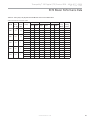
ECM Blower Control
Blower Data
DXM2 Controls
DXM2 Layout and Connection
Unit Commissioning
And Operating Conditions
Unit Start-Up and Operating Conditions
Unit Start-Up Procedure
Coax Pressure Drop Table
Unit Operating Conditions
Performance Data
Preventive Maintenance
Troubleshooting
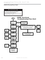
DXM2 Process Flow Chart
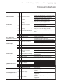
Functional & Performance Troubleshooting
Troubleshooting Form
Warranty
Revision History
29
30-33
34
35
36
37
38
39
39-41
41
42-43
44-48
49
50-52
52
53-56
57
58
60
This page was intentionally left blank.
Tranquility ® 30 Digital (TE) Series IOM - 60Hz HFC-410A
R e v. : 2 7 F e b . , 2 0 1 3 B
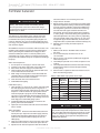
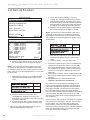
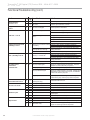
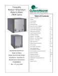
Model Nomenclature: General Overview
1 2
3
4 5 6
7
TE
V 026 A G D 0
8
9
10
11
12
13
14
15
2 C L T S
STANDARD
SERIES
S = Standard
TE = Tranquility 30 Digital
SUPPLY AIR FLOW &
MOTOR CONFIGURATION
CONFIGURATION
T
B
S
D
V = Vertical Up
H = Horizontal
D = Down Flow
UNIT SIZE
026
038
049
064
072
Supply Configuration
Top
TEV
TEH
Back
TEH
Straight
TED
Down
RETURN AIR FLOW CONFIGURATION
L = Left Return w/ 2” Merv 11 pleated filter and frame
R = Right Return w/ 2” Merv 11 pleated filter and frame
HEAT EXCHANGER OPTIONS
REVISION LEVEL
HWG W/Pump (Standard)
No HWG
A = Current Revision
Copper Cupro-Nickel
C
N
A
J
VOLTAGE
G = 208-230/60/1
1
WATER CIRCUIT OPTIONS
2 = Internal Flow Controller - Closed Loop
5 = Motorized Modulating Valve (Central Pumping Applications) - Closed Loop
6 = Motorized Modulating Valve (Ground Water Applications) - Open Loop
CONTROLS
D = DXM2
CABINET
0 = Residential
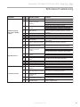
In Position 11 and 12, only the following combinations are available:
With HWG
2C
Without HWG Description
2A
Internal Flow Controller with Copper Water Coil
5C
5A
Motorized Modulating Valve with Copper Water Coil
6N
6J
Motorized Modulating Valve with Cupro-Nickel Water Coil
NOTE: Above model nomenclature is a general reference. Consult individual specification sections for detailed information.
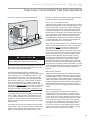
Safety
Warnings, cautions and notices appear throughout this
manual. Read these items carefully before attempting any
installation, service, or troubleshooting of the equipment.
CAUTION: Indicates a potentially hazardous situation or an
unsafe practice, which if not avoided could result in minor or
moderate injury or product or property damage.
DANGER: Indicates an immediate hazardous situation, which
if not avoided will result in death or serious injury. DANGER
labels on unit access panels must be observed.
NOTICE: Notification of installation, operation or maintenance
information, which is important, but which is not hazardrelated.
WARNING: Indicates a potentially hazardous situation, which
if not avoided could result in death or serious injury.
WARNING!
WARNING!
WARNING! The EarthPure® Application and Service
Manual should be read and understood before attempting
to service refrigerant circuits with HFC-410A.
WARNING! All refrigerant discharged from this unit must
be recovered WITHOUT EXCEPTION. Technicians must
follow industry accepted guidelines and all local, state,
and federal statutes for the recovery and disposal of
refrigerants. If a compressor is removed from this unit,
refrigerant circuit oil will remain in the compressor. To
avoid leakage of compressor oil, refrigerant lines of the
compressor must be sealed after it is removed.
WARNING!
CAUTION!
WARNING! To avoid the release of refrigerant into the
atmosphere, the refrigerant circuit of this unit must be
serviced only by technicians who meet local, state, and
federal proficiency requirements.
CAUTION! To avoid equipment damage, DO NOT use
these units as a source of heating or cooling during the
construction process. The mechanical components and
filters will quickly become clogged with construction dirt
and debris, which may cause system damage.
c l i m a t e m a s t e r. c o m
3
Tranquility ® 30 Digital (TE) Series IOM - 60Hz HFC-410A
R e v. : 2 7 F e b . , 2 0 1 3 B
General Information
Inspection
Upon receipt of the equipment, carefully check the shipment
against the bill of lading. Make sure all units and accessories
have been received. Inspect the packaging of each unit, and
inspect each unit for damage. Insure that the carrier makes
proper notation of any shortages or damage on all copies of
the freight bill and completes a common carrier inspection
report. Concealed damage not discovered during unloading
must be reported to the carrier within 15 days of receipt of
shipment. If not filed within 15 days, the freight company can
deny the claim without recourse. Note: It is the responsibility of
the purchaser to file all necessary claims with the carrier. Notify
your equipment supplier of all damage within fifteen (15) days
of shipment.
Storage
Equipment should be stored in its original packaging in a
clean, dry area. Store units in an upright position at all times.
Stack units a maximum of 3 units high.
Unit Protection
Cover units on the job site with either the original packaging
or an equivalent protective covering. Cap the open ends
of pipes stored on the job site. In areas where painting,
plastering, and/or spraying has not been completed, all due
precautions must be taken to avoid physical damage to the
units and contamination by foreign material. Physical damage
and contamination may prevent proper start-up and may
result in costly equipment clean-up.
Examine all pipes, fittings, and valves before installing any of
the system components. Remove any dirt or debris found in
or on these components.
Pre-Installation
Installation, Operation, and Maintenance instructions are
provided with each unit. Horizontal equipment is designed
for installation in an attic or crawl space. Other unit
configurations are typically installed in a mechanical closet
or basement. The installation site chosen should include
adequate service clearance around the unit. Before unit startup, read all manuals and become familiar with the unit and its
operation. Thoroughly check the system before operation.
Prepare units for installation as follows:
1. Compare the electrical data on the unit nameplate with
ordering and shipping information to verify that the correct
unit has been shipped.
2. Keep the cabinet covered with the original packaging until
installation is complete and all plastering, painting, etc. is
finished.
3. Verify refrigerant tubing is free of kinks or dents and that it
does not touch other unit components.
4. Inspect all electrical connections. Connections must be
clean and tight at the terminals.
5. Remove any blower support packaging (water-to-air
units only).
6. Locate and verify any hot water generator (HWG), hanger,
or other accessory kit located in the compressor section
or blower section.
4
CAUTION!
CAUTION! DO NOT store or install units in corrosive
environments or in locations subject to temperature or
humidity extremes (e.g., rooftops, etc. See Tables 12a
and 12b for acceptable temperature ranges). Corrosive
conditions and high temperature or humidity can
significantly reduce performance, reliability, and service
life. Always move and store units in an upright position.
Tilting units on their sides may cause equipment damage.
CAUTION!
CAUTION! CUT HAZARD - Failure to follow this caution
may result in personal injury. Sheet metal parts may have
sharp edges or burrs. Use care and wear appropriate
protective clothing, safety glasses and gloves when
handling parts and servicing heat pumps.
Duct System Installation
The duct system should be sized to handle the design
airflow quietly. Refer to Figure 6 for horizontal duct system
details or Figure 1 for vertical duct system details. A flexible
connector is recommended for both discharge and return
air duct connections on metal duct systems to eliminate
the transfer of vibration to the duct system. To maximize
sound attenuation of the unit blower, the supply and return
plenums should include internal fiberglass duct liner or be
constructed from ductboard for the first few feet. Application
of the unit to uninsulated ductwork in an unconditioned
space is not recommended, as the unit’s performance will be
adversely affected.
At least one 90° elbow should be included in the supply
duct to reduce air noise. If air noise or excessive air flow is
a problem, the blower speed can be changed. For airflow
charts, consult catalog specifications for the series and
model of the specific unit.
If the unit is connected to existing ductwork, a previous
check should have been made to insure that the ductwork
has the capacity to handle the airflow required for the unit.
If ducting is too small, as in the replacement of a heating
only system, larger ductwork should be installed. All existing
ductwork should be checked for leaks and repaired as
necessary.
The installation of geothermal heat pump units and all
associated components, parts and accessories which
make up the GHP system shall be in accordance with the
regulations of ALL authorities having jurisdiction and MUST
conform to all applicable codes. It is the responsibility of
the installing contractor to determine and comply with ALL
applicable codes and regulations.
Geothermal Heat Pump Systems
Tranquility ® 30 Digital (TE) Series IOM - 60Hz HFC-410A
R e v. : 2 7 F e b . , 2 0 1 3 B
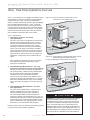
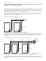
Vertical Installation
Vertical Unit Location
Packaged units are not designed for outdoor installation.
Locate the unit in an INDOOR area that allows enough space
for service personnel to perform typical maintenance or
repairs without removing the unit from the installed location.
Vertical units are typically installed in a mechanical closet
or basement. Never install units in areas subject to freezing
or where humidity levels could cause cabinet condensation
(such as unconditioned spaces subject to 100% outside air).
Also, provide sufficient room to make water, electrical, and
duct connection(s).
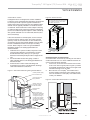
Figure 2: Service Access
Legend
CAP=Compressor and Control Access Panel
CSP=Optional Compressor Service Panel
BSP=Blower Service Panel
BSP
If the unit is located in a confined space, such as a closet,
provisions must be made for return air to freely enter the
space by means of a louvered door or other method. Any
access panel screws that would be difficult to remove after
the unit is installed should be removed prior to setting
the unit. Refer to Figures 1 and 2 for typical installation
illustrations. Refer to unit catalog specifications for
dimensional data.
1. Install the unit on a piece of rubber, neoprene or other
mounting pad material for sound isolation. The pad
should be at least 3/8” [10mm] to 1/2” [13mm] in
thickness. Extend the pad beyond all four edges of the
unit.
2. Do not block filter access with piping, conduit or
other materials. Refer to unit catalog specifications for
dimensional data.
3. Provide access to water valves and fittings and
screwdriver access to the unit side panels, discharge
collar and all electrical connections.
Figure 1: Vertical Unit Mounting Using Ducted Return
Internally insulate supply
duct to reduce noise
Use turning vanes in
supply transition
Access Panel
2' (61cm)
Optional
Service
Access
Left Rtn
CSP
(right
Opposite)
CAP
2' (61cm)
Service
Isometric
View
Sound Attenuation for Vertical Units
Sound attenuation is achieved by enclosing the unit within a
small mechanical room or a closet. Additional measures for
sound control include the following:
1.
If free return, mount the unit so that the return air inlet
is 90° to the return air grille (refer to Figure 3). Install a
sound baffle as illustrated to reduce line-of sight sound
transmitted through return air grilles.
2.
Mount the unit on a Tranquility® Unit Isolation Pad to
minimize vibration transmission to the building structure.
For more information on Tranquility® Unit Isolation Pads,
contact your distributor.
Figure 3: Vertical Sound Attenuation - Free Return
Flexible canvas duct
connector to reduce
noise and vibration
Rounded return
transition
Remove supply duct
flanges from inside blowe
compartment and install
on supply air opening of
unit. Do not use a supply
air plenum/duct smaller
than the size of the supply
duct flanges.
Internally insulate return
transition duct to reduce noise
Minumum
Space 10-12”
Return
Air Inlet
Air Pad or extruded
polystyrene insulation board
c l i m a t e m a s t e r. c o m
5
Tranquility ® 30 Digital (TE) Series IOM - 60Hz HFC-410A
R e v. : 2 7 F e b . , 2 0 1 3 B
Horizontal Installation
Horizontal Unit Location
Packaged units are not designed for outdoor installation.
Locate the unit in an INDOOR area that allows enough space
for service personnel to perform typical maintenance or
repairs without removing unit from the ceiling. Horizontal units
are typically installed in an attic or crawl space. Never install
units in areas subject to freezing or where humidity levels
could cause cabinet condensation (such as unconditioned
spaces subject to 100% outside air). Consideration should
be given to access for easy removal of the filter and access
panels. Provide sufficient room to make water, electrical, and
duct connection(s).
If the unit is located in a confined space, such as a closet,
provisions must be made for return air to freely enter the
space by means of a louvered door or return duct. Any access
panel screws that would be difficult to remove after the unit is
installed should be removed prior to setting the unit. Refer to
Figure 6 for an illustration of a typical installation. Refer to unit
catalog specifications for dimensional data.
Conform to the following guidelines when selecting a
unit location:
1. Provide a hinged access door in concealed-spline or
plaster ceilings. Provide removable ceiling tiles in T-bar
or lay-in ceilings. Refer to horizontal unit dimensions for
specific series and model in unit catalog specifications.
Size the access opening to accommodate the service
technician during the removal or replacement of the
compressor and the removal or installation of the unit
itself.
2. Provide access to hanger brackets, water valves and
fittings. Provide screwdriver clearance to access panels,
discharge collars and all electrical connections.
3. DO NOT obstruct the space beneath the unit with piping,
electrical cables and other items that prohibit future
removal of components or the unit itself.
4. Use a manual portable jack/lift to lift and support the
weight of the unit during installation and servicing.
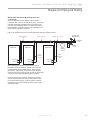
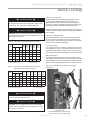
Mounting Horizontal Units
Horizontal units have hanger kits pre-installed from the
factory as shown in Figure 4. Figure 6 shows a typical
horizontal unit installation.
Horizontal heat pumps are typically suspended above a
ceiling or within a soffit using field supplied, threaded rods
sized to support the weight of the unit.
Use four (4) field supplied threaded rods and factory provided
vibration isolators to suspend the unit. Hang the unit clear
of the floor slab above and support the unit by the mounting
bracket assemblies only. DO NOT attach the unit flush with
the floor slab above.
Pitch the unit toward the drain as shown in Figure 5 to
improve the condensate drainage. On small units (less
than 2.5 Tons/8.8 kW) ensure that unit pitch does not cause
condensate leaks inside the cabinet.
Horizontal units may also be installed on a base. When
installed on a base or platform the horizontal unit should be
set in a secondary drain pan on top of a vibration absorbing
pad. This is required by many codes. The secondary drain
pan prevents damage to the building structure by possible
condensate overflow or water leakage.
NOTE: The top panel of a horizontal unit is a structural
component. The top panel of a horizontal unit must never
be removed from an installed unit unless the unit is properly
supported from the bottom. Otherwise, damage to the unit
cabinet may occur.
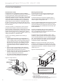
Figure 5: Horizontal Unit Pitch
CAP
2’ [61cm] Service
Access
Front
Return Air
2’ [61cm] optional
service access
CSP
Figure 4: Hanger Bracket
>PP@7KUHDGHG
5RGE\RWKHUV
1/4” (6.4mm) pitch
per foot for drainage
9LEUDWLRQ,VRODWRU
IDFWRU\VXSSOLHG
Straight
Discharge
Drain
Connection
:DVKHU
E\RWKHUV
Back
Discharge
Legend
CAP=Compressor and Control Access Panel
CSP=OptionalCompressor Service Panel
BSP=Blower Service Panel
'RXEOH+H[1XWV
E\RWKHUV
Notes:
1. While clear access to all removable panels is not required, installer should
take care to comply with all building codes and allow adequate clearance
for future field service.
2. Blower service panel requires 2’ service access.
3. Blower service access is through back panel on straight discharge units or
through panel opposite air coil on back discharge units.
6
Geothermal Heat Pump Systems
Tranquility ® 30 Digital (TE) Series IOM - 60Hz HFC-410A
R e v. : 2 7 F e b . , 2 0 1 3 B
Horizontal Installation
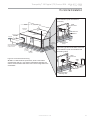
Figure 6a: Typical Closed Loop Horizontal
Unit Installation (with Internal Flow
Controller)
Water
Pressure Ports
3/8" [10mm] threaded rods
(by others)
Flexible Duct
Connector
Return
Duct
Water Out
Water In
Power Wiring
Use turning vanes
or a double
radius elbow
Supply Air
Unit Power
Vibration
Isolation Pad
Insulated supply duct with
at least one 90 deg turn
to reduce air noise
Flexible Duct
Connector
Unit Power
Disconnect
(by others)
Secondary
Drain Pan
Platform
Unit
Hanger Thermostat
Wiring
Internal
Variable-Speed
Pump
Flush
Ports
Figure 6b: Typical Ground Water Horizontal
Unit Installation (with Internal Motorized
Modulating Valve)
Water
Pressure Ports
Figure 6: Horizontal Unit Mounting
Air Coil - To obtain maximum performance, the air coil should be
cleaned before start-up. A 10% solution of dishwasher detergent and
water is recommended for both sides of the coil. A thorough water rinse
should follow.
:DWHU
2XW
Pressure
Tank
:DWHU,Q
Internal Motorized
Modulating Valve
c l i m a t e m a s t e r. c o m
Boiler
Drains
Ball Valves
7
Tranquility ® 30 Digital (TE) Series IOM - 60Hz HFC-410A
R e v. : 2 7 F e b . , 2 0 1 3 B
Horizontal Installation
Field Conversion of Air Discharge
Figure 7: Left Return Side to Back
Overview - Horizontal units can be field converted
between side (straight) and back (end) discharge using the
instructions below.
Remove Screws
Water
Connection End
Return Air
Note: It is not possible to field convert return air between left
or right return models due to the necessity of refrigeration
copper piping changes.
Preparation - It is best to field convert the unit on the ground
before hanging. If the unit is already hung it should be taken
down for the field conversion.
Side to Back Discharge Conversion
Place unit in well lit area. Remove the screws as shown
1.
in Figure 7 to free top panel and discharge panel.
2.
Lift out the access panel and set aside. Lift and rotate
the discharge panel to the other position as shown,
being careful with the blower wiring.
3.
Check blower wire routing and connections for tension or
contact with sheet metal edges. Reroute if necessary.
4.
Check refrigerant tubing for contact with
other components.
5.
Reinstall top panel and screws noting that the location
for some screws will have changed.
6.
Manually spin the fan wheel to ensure that the wheel is
not rubbing or obstructed.
7.
Replace access panels.
Side Discharge
Water
Connection End
Rotate
Return Air
Move to Side
Replace Screws
Water
Connection End
Return Air
Back to Side Discharge Conversion - If the discharge is
changed from back to side, use above instruction noting that
illustrations will be reversed.
Left vs. Right Return - It is not possible to field convert
return air between left or right return models due to the necessity of refrigeration copper piping changes. However, the
conversion process of side to back or back to side discharge
for either right or left return configuration is the same. In
some cases, it may be possible to rotate the entire unit 180
degrees if the return air connection needs to be on the opposite side. Note that rotating the unit will move the piping to
the other end of the unit.
Drain
Discharge Air
Back Discharge
Figure 8: Right Return Side to Back
Water
Connection End
Return Air
Supply Duct
Side Discharge
Return Air
Drain
Discharge Air
8
Geothermal Heat Pump Systems
Back Discharge
Water
Connection End
Tranquility ® 30 Digital (TE) Series IOM - 60Hz HFC-410A
R e v. : 2 7 F e b . , 2 0 1 3 B
Condensate and Water Connection
Condensate Piping
Pitch the unit toward the drain as shown in Figure 5 to
improve the condensate drainage. On small units (less
than 2.5 tons/8.8 kW), insure that unit pitch does not cause
condensate leaks inside the cabinet.
Install condensate trap at each unit with the top of the trap
positioned below the unit condensate drain connection as
shown in Figure 9. Design the depth of the trap (waterseal) based upon the amount of External Static Pressure
(ESP) capability of the blower (where 2 inches [51mm] of
ESP capability requires 2 inches [51mm] of trap depth). As a
general rule, 1-1/2 inch [38mm] trap depth is the minimum.
Each unit must be installed with its own individual trap and
connection to the condensate line (main) or riser. Provide
a means to flush or blow out the condensate line. DO NOT
install units with a common trap and/or vent.
Water Connections-Residential (Distributor) Models
Residential models utilize swivel piping fittings for water
connections that are rated for 450 psi (3101 kPa) operating
pressure. The connections have a rubber gasket seal similar
to a garden hose gasket, which when mated to the flush
end of most 1” threaded male pipe fittings provides a leakfree seal without the need for thread sealing tape or joint
compound. Check for burrs and ensure that the rubber seal
is in the swivel connector prior to attempting any connection
(rubber seals are shipped attached to the swivel connector).
DO NOT OVER TIGHTEN or leaks may occur.
The female locking ring is threaded onto the pipe threads
which holds the male pipe end against the rubber gasket,
and seals the joint. HAND TIGHTEN ONLY! DO NOT
OVERTIGHTEN!
Figure 10: Water Connections
Always vent the condensate line when dirt or air can collect
in the line or a long horizontal drain line is required. Also vent
when large units are working against higher external static
pressure than other units connected to the same condensate
main since this may cause poor drainage for all units on
the line. WHEN A VENT IS INSTALLED IN THE DRAIN
LINE, IT MUST BE LOCATED AFTER THE TRAP IN THE
DIRECTION OF THE CONDENSATE FLOW.
Figure 9: Condensate Connection
Swivel Nut
Stainless steel
snap ring
Hand Tighten
Only!
Do Not
Overtighten!
Gasket
Brass Adaptor
ರ
ರ3HU
)RRW
ರ
ರ
* Some units include a painted drain connection.
Using a threaded pipe or similar device to clear
any excess paint accumulated inside this fitting
may ease final drain line installation.
CAUTION!
CAUTION! Ensure condensate line is pitched toward drain
1/8 inch per ft [11mm per m] of run.
c l i m a t e m a s t e r. c o m
9
Tranquility ® 30 Digital (TE) Series IOM - 60Hz HFC-410A
R e v. : 2 7 F e b . , 2 0 1 3 B
vFlow™ Heat Pump Applications Overview
vFlow™ is a revolutionary new, intelligent, and efficient way to
circulate water (or water plus antifreeze) using INTERNAL,
variable water flow control. The factory-installed highefficiency variable-speed pump uses 60%-80% less wattage
than a traditional fixed speed pump. vFlow™ technology
improves performance of the unit by reducing the amount
of energy required to optimize the flow of water throughout
a GHP System and also reduces the space, cost, and labor
required to install external water flow control mechanisms
(flow controllers, solenoid and flow control valves).
vFlow™ Configurations:
1) Internal Flow Controller - For Closed
Loop Applications
This is the most common configuration for closed loops.
With this factory-installed standard option, the unit is
built with an Internal Variable Speed Pump and other
components to flush and operate the unit correctly
(including an expansion tank, flush ports and flushing
valves). The pump speed is controlled by the DXM2
control based on the difference in entering and leaving
water temperatures (∆T). The Internal Flow Controller
pump includes an internal check valve for multiple unit
installations. A copper water coil is standard with this
option.
Note: Internal Flow Controllers are also very suitable
for multiple unit installations depending on pump
performance requirements.
2) Internal Modulating Motorized Valve – For Large
Closed Loop Applications (external central pumping)
Primarily for use on multi-unit closed loop applications
with central pumping. With this factory-installed option,
the unit includes a low pressure drop modulating
motorized valve that is controlled by the DXM2
microprocessor control based on the difference in the
entering and leaving water temperatures (∆T). A Copper
Water Coil is standard with this option. The modulating
valve in this option has a higher Cv than the open loop
option.
3) Internal Modulating Motorized Valve - For Open
Loop Applications
For use on open loop applications. With this factoryinstalled, standard option, the unit is built with an
internal modulating motorized valve controlled by
the Communicating DXM2 control board based on
entering and leaving water temperatures (∆T). A low Cv
modulating motorized valve is used for this application to
provide more precise control against the higher system
pressure differential of open loop applications. A CuproNickel water coil comes standard with this option.
Details on these options are included in the following sections
on ground loop and ground water applications.
10
Figure 11a: Typical Closed-Loop Application (with
Internal Flow Controller Shown)
To Thermostat
Internal Flow
Controller
Water Out
High and
Low Voltage
Knockouts
Water In
Vibration Isolation Pad
Figure 11b: Typical Open Loop Application (with Internal
Modulating Motorized Valve Shown)
For use on applications using external source for flow
To Thermostat
Internal Motorized
Modulating Valve
Pressure
Tank
Water Out
Water In
High and
Low Voltage
Knockouts
Boiler
Drains
Shut Off
Ball Valves
for Isolation
Optional
Filter
Vibration Isolation Pad
CAUTION!
CAUTION! The following instructions represent industry
accepted installation practices for closed loop earth
coupled heat pump systems. Instructions are provided
to assist the contractor in installing trouble free ground
loops. These instructions are recommendations only.
State/provincial and local codes MUST be followed and
installation MUST conform to ALL applicable codes. It is
the responsibility of the installing contractor to determine
and comply with ALL applicable codes and regulations.
Geothermal Heat Pump Systems
Tranquility ® 30 Digital (TE) Series IOM - 60Hz HFC-410A
R e v. : 2 7 F e b . , 2 0 1 3 B
Closed Loop Heat Pump Applications with Internal Flow Controller
Units with internal flow control come with a built-in variable
speed pump, an expansion tank, flushing ports and threeway valves (used to flush the unit). The variable speed
pump is controlled by the Communicating DXM2 board
based on the difference between the entering and leaving
water temperature (∆T). For operation outside of the normal
entering water temperature range (50° or 60°F - 110°F
for cooling, 30°F-70°F for heating) the DXM2 controller
may automatically adjust the control ∆T to account for
the abnormal entering water temperatures, maintaining
an appropriate flow rate for proper unit operation. When
entering water temperatures are abnormally low for cooling,
or abnormally high for heating, the DXM2 controller will
maintain a constant leaving water temperature which will
allow the unit to operate properly under those conditions.
The internal expansion tank helps to maintain constant loop
pressure despite the natural expansion and contraction of
the loop as the seasons and loop temperatures vary. The
expansion tank also helps to avoid flat loop callbacks.
Pre-Installation
Prior to installation, locate and mark all existing underground
utilities, piping, etc. Install loops for new construction before
sidewalks, patios, driveways, and other construction has
begun. During construction, accurately mark all ground loop
piping on the plot plan as an aid in avoiding potential future
damage to the installation.
Piping Installation
The typical closed loop ground source system is shown in
Figures 6a and 11a. All earth loop piping materials should be
limited to polyethylene fusion only for in-ground sections of the
loop and it is also recommended for inside piping. Galvanized
or steel fittings should not be used at any time due to their
tendency to corrode. All plastic to metal threaded fittings
should be avoided due to their potential to leak in ground
loop applications. Loop temperatures can range between
25 and 110°F [-4 to 43°C]. Flow rates between 2.25 and 3
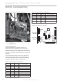
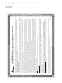
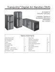
Figure 13: Magna Geo 25-140 Pump Performance
Magna Geo 25-140 Pump Curve
60
50
Figure 12: Internal Flow Controller
gpm per ton [2.41 to 3.23 l/m per kW] of cooling capacity is
recommended in these applications.
Test individual horizontal loop circuits before backfilling.
Test vertical U-bends and pond loop assemblies prior to
installation. Pressures of at least 100 psi [689 kPa] should be
used when testing. Do not exceed the pipe pressure rating.
Test entire system when all loops are assembled.
NOTICE!
NOTICE! If installing MULTIPLE vFlow™ Internal Variable
Speed Flow Controller units (in parallel) on one loop,
please refer to section ‘Multiple Unit Piping and Flushing’
(later in this document).
The following section will help to guide you through flushing a
unit with internal flow control.
Water Pressure Schrader Ports
The pressure ports built in to the unit are provided as a
means of measuring pressure drop through the water-torefrigerant heat exchanger. The water pressure ports are
schrader ports smaller than refrigerant schrader ports. They
are the same size as tire schrader ports. A digital pressure
gauge is recommended for taking pressure readings
through these ports. The water flow through the unit can be
determined by measuring the water pressure at the “water
pressure out” port and subtracting it from the
water pressure at the “water
GPM Head (ft)
pressure in” port. Comparing
0.0
44.7
1.0
45.4
the pressure differential to the
2.0
46.1
pressure drop table (wpd)/flow
3.0
46.8
4.0
47.5
rate in Tables 17a through 17e
5.0
47.7
in this manual will determine the
6.0
47.1
7.0
46.1
flow rate through the unit.
Head (Ft.)
40
30
20
10
0
0
5
10
15
20
25
30
35
Flow (GPM)
c l i m a t e m a s t e r. c o m
40
8.0
9.0
10.0
11.0
12.0
13.0
14.0
15.0
16.0
17.0
18.0
19.0
20.0
21.0
22.0
23.0
24.0
25.0
45.3
43.9
42.6
41.2
39.9
38.7
37.4
36.1
34.9
33.7
32.5
31.3
30.1
28.9
27.8
26.7
25.6
24.5
Digital Pressure Gauge
11
Tranquility ® 30 Digital (TE) Series IOM - 60Hz HFC-410A
R e v. : 2 7 F e b . , 2 0 1 3 B
Flushing the Earth Loop
Once piping is completed between the unit and the ground
loop, final purging and charging of the loop is needed.
A flush cart (at least a 1.5 hp [1.1kW] pump) is needed
to achieve adequate flow velocity in the loop to purge air
and dirt particles from the loop itself. Antifreeze solution is
used in most areas to prevent freezing. All air and debris
must be removed from the earth loop piping system before
operation, Flush the loop with a high volume of water at
a high velocity (2 fps [0.6 m/s] in all piping), using a filter
in the loop return line, of the flush cart to eliminate debris
from the loop system. See Table 1 for flow rate required to
attain 2fps [0.6 m/s]. The steps below must be followed for
proper flushing.
WARNING!
WARNING! Disconnect electrical power source to prevent
injury or death from electrical shock.
Figure 14b: Cam Fittings for Flush Cart Hoses
Attach
to Flow
Controller
Flush Port
Connect
to Flush
Cart Hose
(1 of 2)
Table 1: Minimum Flow Required to Achieve 2 ft/sec
variety
PE Pipe Size
Flow (GPM)
3/4"
4
1"
6
1 1/4"
10
1 1/2"
13
2"
21
Units with internal variable speed pumps also include a
check valve internal to the pump. It is not possible to flush
backwards through this pump. Care must be taken to
connect the flush cart hoses so that the flush cart discharge is
connected to the “water in” flushing valve of the heat pump.
NOTICE: A hydrostatic pressure test is required on ALL piping,
especially underground piping before final backfill per IGSHPA
and the pipe manufacturers recommendations.
Figure 15a: Valve Position A - Loop Fill/Flush
Loop Fill
Fill loop (valve position A, see Figure 15a) with water from a
garden hose through flush cart before using flush cart pump
to ensure an even fill and increase flushing speed. When
water consistently returns back to the flush reservoir, switch
to valve position B (figure 15b).
Isolate expansion tank for flushing procedure using the ball
valve. During dead heading of flush cart pump, isolation will
prevent compression of bladder in the expansion tank and
flush cart fluid level dropping below available capacity.
Loop
Figure 14a: Typical Cleanable Flush
Cart Strainer (100 mesh [0.149mm])
Valve Position
Flush Port
Out
In
Front of Unit
Valve Position
12
Geothermal Heat Pump Systems
Tranquility ® 30 Digital (TE) Series IOM - 60Hz HFC-410A
R e v. : 2 7 F e b . , 2 0 1 3 B
Flushing the Earth Loop
Figure 15b: Valve Position B - Unit Fill / Flush
NOTICE: Actual flushing time require will vary for each
installation due to piping length, configuration, and flush
cart pump capacity. 3/8” or less fluid level drop is the ONLY
indication that flushing is complete.
Switch valves to Position B to flush the unit. Flush through
the unit until all air pockets have been removed.
Loop
Move valves to position C. By switching both valves to this
position, water will flow through the loop and the unit heat
exchanger. Finally, the dead head test should be checked
again for an indication of air in the loop. Fluid level drop is
your only indication of air in the loop.
Figure 15c: Valve Position C - Full Flush
Valve Position
Flush Port
Out
Add Antifreeze
Now if Needed
Dead Head
Pump Test
for Air
In
Loop
Front of Unit
Valve Position
Loop Flush
Switch to valve Position A. The supply water may be shut off
and the flush cart turned on to begin flushing. Once the flush
reservoir is full, do not allow the water level in the flush cart
tank to drop below the pump inlet line or air can be pumped
back out to the earth loop. Try to maintain a fluid level in the
tank above the return tee so that air can not be continuously
mixed back into the fluid. Surges of 50 psi [345 kPa] can
be used to help purge air pockets by simply shutting off
the flush cart return valve going into the flush cart reservoir.
This process ‘dead heads’ the pump to 50 psi [345 kPa]. To
dead head the pump until maximum pumping pressure is
reached, open the valve back up and a pressure surge will
be sent through the loop to help purge air pockets from the
piping system. Notice the drop in fluid level in the flush cart
tank. If all air is purged from the system, the level will drop
only 3/8” in a 10” [25.4 cm] diameter PVC flush tank (about
a half gallon [1.9 liters]) since liquids are incompressible. If
the level drops more than this level, flushing should continue
since air is still being compressed in the loop fluid. Do this a
number of times.
Valve Position
Out
Flush Port
Unit Fill
Unit fill valves should be switched to Position B while flush
cart is pumping to fill the unit heat exchanger (see Figure
15b). The valves position should be maintained until water is
consistently returned into the flush reservoir.
In
Front of Unit
Valve Position
Pressurize and Operate
As shown in Figure 15d, close the flush cart return valve
to pressurize the loop to at least 50 psi [345 kPa], not to
exceed 75 psi [517 kPa]. Open the isolation valve to the
expansion tank and bleed air from the expansion tank piping
using the schraeder valve located in front of the expansion
tank. This will allow loop pressure to compress the
expansion tank bladder, thus charging the expansion tank
with liquid. After pressurizing, close the flush cart supply
valve to isolate the flush cart. Move the Flow Controller
valves to Position D.
Loop static pressure will fluctuate with the seasons and
pressures will be higher in the winter months than during
the cooling season. This fluctuation is normal and should
be considered when charging the system initially. Unhook
c l i m a t e m a s t e r. c o m
13
Tranquility ® 30 Digital (TE) Series IOM - 60Hz HFC-410A
R e v. : 2 7 F e b . , 2 0 1 3 B
Flushing the Earth Loop
the flush cart from the Internal Flow Controller. Install Flow
Controller caps to ensure that any condensation/leakage
remains contained within the Flow Controller package.
If the loop pressure is between 50 and 75 psi [345 to 517
kPa] upon completion of flushing, pressures should be
sufficient for all seasons.
NOTICE: It is recommended to run the unit in the cooling,
then heating mode for 15-20 minutes each to ‘temper’ the
fluid temperature and prepare it for pressurization. This
procedure helps prevent the periodic “flat” loop condition of
no pressure.
Figure 15d: Valve Position D - Pressurize and Operation
2
Close to isolate
Internal Flow Controller
3
Close Internal
Flow Controller
Valves for
Operation Mode
1
Dead Head
Pump to
Pressurize
to 50 PSI
Loop
Valve Position
Flush Port
Out
In
Front of Unit
Valve Position
14
Geothermal Heat Pump Systems
Tranquility ® 30 Digital (TE) Series IOM - 60Hz HFC-410A
R e v. : 2 7 F e b . , 2 0 1 3 B
Multiple Unit Piping and Flushing
Often projects require more than one heat pump. Where
possible, it makes sense for multiple units to share a common
ground loop. Common ground loops for multiple units bring
new challenges including the need to avoid backward flow
through inactive units, increased pumping requirements,
and more complex flushing needs. Three types of multiple
unit systems are described below along with guidelines for
installation of each type.
vFlow™ internal variable flow technology is a great assist
for systems with multiple units. vFlow™ is available in three
different configurations:
1. Internal variable-speed pump
2. Internal modulating valve for closed loops
3. Internal modulating valve for open loops
The internal modulating valve for open loops version should
never be used on closed loops.
The internal variable speed pump version of vFlow™includes
an internal Magna variable speed circulator controlled by
the DXM2 microprocessor, internal 3-way flushing valves,
an internal bladder type expansion tank, and front-mounted
pressure ports that allow access to the pressure drop across
the coaxial heat exchanger only. The Magna pump includes
an internal check valve. The pump curve for the Magna
circulator is shown in Figure 13. The internal expansion tank
will operate as a pressure battery for the geothermal system.
It will absorb fluid from the loop when loop pressure rises
and inject fluid into the loop when loop pressure falls. In this
way the expansion tank will help to maintain a more constant
loop pressure and avoid flat loops due to seasonal pressure
changes in the loop.
When using the internal variable speed pump as the loop
pump in multiple unit installations it is important to ensure
that the variable speed pump can provide adequate flow
through the heat pump against the loop head when all units
are operating.
It may be possible to flush a multiple unit system through
the unit’s flushing valves. Flushing pressure drop of the
valve may be calculated to determine if it is acceptable.
Engineering data for the 3-way flushing valves can be found
in Table 2.
Table 2: Internal 3-Way Flushing Valve Data
Model
Flushing
Connection
Straight
Flow Cv
90°
Flow Cv
TE026 - 038
3/4" FPT
25
10.3
TE049 - 072
1" FPT
58
14.5
For example, if a system includes two 2-ton units and four ¾
loop circuits we can calculate the flushing pressure drop as
follows. From Table 1 we know that it will take 4 gpm to flush
each ¾” circuit. If there is no provision to isolate the circuits
for flushing, we will have to flush with a minimum of 4 circuits
x 4 gpm/circuit = 16 gpm total. A check of other piping sizes
used must be done to ensure that 16 gpm total flow will flush
all piping.
Pressure drop through the flushing valve can be calculated
using the following formula.
∆P = (GPM/Cv)2 where,
∆P = pressure drop in psi through the valve while flushing
GPM = flushing flow in gallons per minute
Cv = valve Cv in flushing mode
We know from Table 2 that the Cv for the flushing valve in
a TE026 is 10.3 in the flushing mode (90° flow). Therefore,
∆P = (GPM/Cv)2 = (16/10.3)2 = 2.4 psi per valve (there are
two flushing valves). So long as the flushing pump is able to
provide 16 gpm at the flushing pressure drop of the loop plus
the 2.4 x 2 valves = 4.8 psi of the flushing valves, the internal
flushing valves may be used. If the flushing pump is not able
to overcome the pressure drop of the internal flushing valves,
then larger external flushing valves must be used.
Unit Configuration
Multiple vFlow™ units with internal variable-speed flow
controller and check valve, piped in parallel sharing a
common loop MUST be configured for ‘VS PUMP PARALLEL’
in Installer Settings Menu.
UNIT CONFIGURATION
CURRENT CONFIG
TE026
HEAT PUMP FAMILY
TE
HEAT PUMP SIZE
026
BLOWER TYPE
ECM
LOOP CONFIG
VS PUMP
PARALLEL
SELECT OPTION
PREVIOUS
Installer Settings
Loop Config
SAVE
System Config
Unit Config
Multiple Units with Internal Flow Controllers
The simplest multiple unit system is one with two (or more)
units utilizing internal Flow Controllers with no external
pumps or flushing valves. In this case the units are piped
in parallel and use the internal flushing valves to flush the
system. The variable speed pump includes an internal check
valve to prevent back (short circuiting) flow through the units.
In this case, flush the loop through the internal flushing
valves in the unit farthest from the loop first. Once the loop is
flushed, then change the internal flushing valves to flush the
heat pump. Next, move the flushing cart to the next closest
unit to the loop.
c l i m a t e m a s t e r. c o m
15
Tranquility ® 30 Digital (TE) Series IOM - 60Hz HFC-410A
R e v. : 2 7 F e b . , 2 0 1 3 B
Multiple Unit Piping and Flushing
Again, flush the loop through the internal flushing valves. This is important as there may be air/debris in the lines from this unit
to the common piping. Once flushing begins the air will be move into the loop and will need to be flushed out. After the loop
is flushed through the second unit, change the flushing valves to flush the second unit. This process should be repeated for
additional units working from the farthest from the loop to the closest to the loop.
This type of application can generally be employed for systems to 12 tons depending on loop design. However, it is important
perform appropriate calculations to confirm that the variable speed pump can provide adequate flow through all heat pumps
against the loop head when all units are operating.
Figure 16a: Multiple Units with Internal Flow Controllers
Size for Heat Pump
‘A’ Flow
Size for ‘A’ + ‘B’ Flow
To Ground
Loop
Heat Pump
A
Heat Pump
B
Size for Heat Pump
‘B’ Flow
Water Out
Water Out
Water In
Water In
Multiple Units with Internal Flow Controllers and External Flushing Valves
When the number of units or flushing requirements reaches a point where it is no longer feasible to flush through the internal
valves (generally systems of more than 12 tons depending on loop design), external flushing valves should be installed. In this
case, three-way flushing valves should be used or additional isolation valves must be installed to be able to isolate the loop
during flushing.
Figure 16b: Multiple Units with Internal Flow Controllers and External Flushing Valves
Size for Heat Pump
‘A’ Flow
Size for ‘A’ + ‘B’ Flow
Size for ‘A’ + ‘B’ + ‘C’ Flow
Ground Loop
Shut-Off Valve
To Ground
Loop
Heat Pump
A
Heat Pump
B
Heat Pump
C
Indoor Loop
Shut-Off Valve
Flush
Valve
Size for
Heat Pump
‘C’ Flow
Size for
Heat Pump
‘B’ Flow
Water Out
Water Out
Water Out
Water In
Water In
Water In
First, flush the ground loop. The installer should close the indoor loop shut-off valve (or the internal flushing valves in all units)
and open the ground loop shut-off valve to prevent flow through the indoor loop while flushing the ground loop.
Once the ground loop is flushed, close the ground loop shut-off valve and open the indoor loop valve(s) to flush the units and
indoor piping. Remember that there is an internal check valve in the variable speed pump and that backward flow the unit is
not possible.
16
Geothermal Heat Pump Systems
Tranquility ® 30 Digital (TE) Series IOM - 60Hz HFC-410A
R e v. : 2 7 F e b . , 2 0 1 3 B
Multiple Unit Piping and Flushing
Multiple Units with Internal Modulating Valves and
Central Pump
This is an application where multiple units are used in
conjunction with a central, variable speed pump. In this case,
units with closed loop modulating valves are used (do not
use open loop modulating valves on a closed loop system).
External flushing valves are required. This application is for
larger systems, including commercial.
Figure 16c: Multiple Units with Internal Modulating Valves and Central Pump
Size for Heat Pump
‘A’ Flow
Size for ‘A’ + ‘B’ Flow
Ground Loop
Shut-Off Valve
Size for ‘A’ + ‘B’ + ‘C’ Flow
To Ground
Loop
Pump
Heat Pump
Heat Pump
Heat Pump
Size for
Heat Pump
‘B’ Flow
Pump
Isolation
Valves
Exp
Tank
Flush
Valve
Size for
Heat Pump
‘C’ Flow
Water Out
Water Out
Water Out
Water In
Water In
Water In
Before flushing, the installer should manually open all
modulating valves as detailed in Closed Loop – External
Central Pumping section of this manual. Next, flush the
ground loop. The installer should close a pump isolation
valve and open the ground loop shut-off valve to prevent flow
through the indoor loop while flushing the ground loop.
Once the ground loop is flushed, close the ground loop
shut-off valve and open the pump isolation valve to flush
the units and indoor piping. Once the system is flushed
remember to return the modulating valves to their normal
operating position.
c l i m a t e m a s t e r. c o m
17
Tranquility ® 30 Digital (TE) Series IOM - 60Hz HFC-410A
R e v. : 2 7 F e b . , 2 0 1 3 B
Ground Loop Heat Pump Applications
Antifreeze Selection - General
In areas where minimum entering loop temperatures drop
below 40°F [4.4°C] or where piping will be routed through
areas subject to freezing, antifreeze is needed. Alcohols
and glycols are commonly used as antifreeze solutions.
Your local representative should be consulted for the
antifreeze best suited to your area. Freeze protection should
be maintained to 15°F [8.5°C] below the lowest expected
entering loop temperature.
Initially calculate the total volume of fluid in the piping
system using Table 3. Then use the percentage by volume
shown in Table 4 for the amount of antifreeze. Antifreeze
concentration should be checked from a well mixed sample
using a hydrometer to measure specific gravity.
Contact your ClimateMaster distributor if you have any
questions as to antifreeze selection.
WARNING!
WARNING! Always use properly marked vehicles (D.O.T.
placards), and clean/suitable/properly identified containers
for handling flammable antifreeze mixtures. Post and
advise those on the jobsite of chemical use and potential
dangers of handling and storage.
NOTICE: DO NOT use automotive windshield washer fluid
as antifreeze. Washer fluid contains chemicals that will cause
foaming.
CAUTION!
Table 3: Fluid Volume
Fluid Volume (gal [liters] per 100’ [30 meters) Pipe)
Pipe
Copper
Polyethylene
Size
Volume (gal) [liters]
1”
4.1 [15.3]
1.25”
6.4 [23.8]
2.5”
9.2 [34.3]
3/4” IPS SDR11
2.8 [10.4]
1” iPS SDR11
4.5 [16.7]
1.25” IPS SDR11
8.0 [29.8]
1.5” IPS SDR11
10.9 [40.7]
2” IPS SDR11
18.0 [67.0]
Unit Heat Exchanger
Typical
1.0 [3.8]
Flush Cart Tank
10” Dia x 3ft tall
[254mm x 91.4cm tall]
10 [37.9]
WARNING!
WARNING! Always dilute alcohols with water (at least 50%
solution) before using. Alcohol fumes are flammable and
can cause serious injury or death if not handled properly.
When handling methanol (or any alcohol), always wear
eye protection and rubber gloves as alcohols are easily
absorbed through the skin.
Table 4: Antifreeze Percentages by Volume
Type
Methanol
Propylene Glycol
Ethanol*
Minimum Temperature
for Low Temperature Protection
10°F
[-12.2°C]
15°F
[-9.4°C]
20°F
[-6.7°C]
25°F
[-3.9°C]
21%
29%
23%
17%
24%
20%
13%
18%
16%
8%
12%
11%
* Must not be denatured with any petroleum based product
18
CAUTION! Always obtain MSDS safety sheets for all
chemicals used in ground loop applications including
chemicals used as antifreeze.
Antifreeze Charging
It is highly recommended to utilize premixed antifreeze fluid
where possible to alleviate many installation problems and
extra labor.
The following procedure is based upon pure antifreeze and
can be implemented during the Full Flush procedure with three
way valves in the Figure 15c - Valve Position C. If a premixed
mixture of 15°F [-9.4°C] freeze protection is used, the system
can be filled and flushed with the premix directly to prevent
handling pure antifreeze during the installation.
1) Flush loop until all air has been purged from system and
pressurize to check for leaks before adding
any antifreeze.
2) Run discharge line to a drain and hook up antifreeze
drum to suction side of pump (if not adding below
water level through approved container). Drain flush cart
reservoir down to pump suction inlet so reservoir can
accept the volume of antifreeze to be added.
3) Calculate the amount of antifreeze required by first
calculating the total fluid volume of the loop from Table 3.
Then calculate the amount of antifreeze needed using Table
4 for the appropriate freeze protection level. Many southern
applications require freeze protection because of exposed
piping to ambient conditions.
4) Isolate unit and prepare to flush only through loop (see
Figure 15a). Start flush cart, and gradually introduce the
required amount of liquid to the flush cart tank (always
introduce alcohols under water or use suction of pump
to draw in directly to prevent fuming) until attaining the
proper antifreeze protection. The rise in flush reservoir
level indicates amount of antifreeze added (some carts
are marked with measurements in gallons or liters). A
ten inch [25.4 cm] diameter cylinder, 3 foot [91.4 cm] tall
holds approximately 8 gallons [30.3 liters] of fluid plus the
hoses (approx. 2 gallons, [7.6 liters], which equals about
Geothermal Heat Pump Systems
Tranquility ® 30 Digital (TE) Series IOM - 60Hz HFC-410A
R e v. : 2 7 F e b . , 2 0 1 3 B
Ground Loop Heat Pump Applications
Chart 1a: Methanol Specific Gravity
Specific Gravity
1.000
0.995
0.990
0.985
0.980
0.975
0.970
0.965
0.960
-50°F -40°F -30°F -20°F -10°F 0°F
10°F 20°F 30°F 40°F 50°F
-45.6°C
-34.4°C
-23.3°C
-12.2°C
-1.1°C
10°C
-40°C
-28.9°C
-17.8°C
-6.7°C
4.4°C
Low Temperature Protection
Chart 1b: Propylene Glycol Specific Gravity
1.07
Specific Gravity
10 gallons [37.9 liters] total. If more than one tankful is
required, the tank should be drained immediately by
opening the waste valve of the flush cart noting the
color of the discharge fluid. Adding food coloring to the
antifreeze can help indicate where the antifreeze is in the
circuit and prevents the dumping of antifreeze out the
waste port. Repeat if necessary.
5) Be careful when handling methanol (or any alcohol).
Always wear eye protection and rubber gloves. The
fumes are flammable, and care should be taken with all
flammable liquids. Open flush valves to flush through
both the unit and the loop and flush until fluid is
homogenous and mixed. It is recommended to run the
unit in the heating and cooling mode for 15-20 minutes
each to ‘temper’ the fluid temperature and prepare it for
pressurization. Devoting this time to clean up can be
useful. This procedure helps prevent the periodic “flat”
loop condition.
6) Close the flush cart return valve; and immediately
thereafter, close the flush cart supply valve, leaving a
positive pressure in the loop of approximately 50 psi [345
kPa]. This is a good time to pressure check the system
as well. Check the freeze protection of the fluid with the
proper hydrometer to ensure that the correct amount of
antifreeze has been added to the system. The hydrometer
can be dropped into the flush reservoir and the reading
compared to Chart 1a for Methanol, 1b for Propylene
Glycol, and 1c for Ethanol to indicate the level of freeze
protection. Do not antifreeze more than a +10°F [-12.2°C]
freeze point. Specific gravity hydrometers are available
in the residential price list. Repeat after reopening and
flushing for a minute to ensure good second sample
of fluid. Inadequate antifreeze protection can cause
nuisance low temperature lockouts during cold weather.
1.06
1.05
1.04
1.03
1.02
1.01
1.00
-40°F
-40°C
-30°F
-20°F
-10°F
0°F
10°F
20°F
-34.4°C -28.9°C -23.3°C -17.8°C -12.2°C -6.7°C
30°F
40°F
-1.1°C
4.4°C
Low Temperature Protection
Chart 1c: Ethanol Specific Gravity
1.000
0.995
0.990
0.985
WARNING!
0.980
WARNING! Always dilute alcohols with water (at least 50%
solution) before using. Alcohol fumes are flammable and
can cause serious injury or death if not handled properly.
5°F
10°F
15°F
20°F
25°F
30°F
35°F
-15.0°C
-12.2°C
-9.4°C
-6.7°C
-3.9°C
-1.1°C
1.7°C
Low Temperature Protection
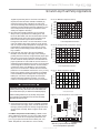
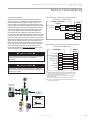
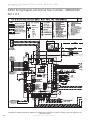
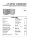
Figure 17: Low Temperature Cutout Selection
Off
LT2
LT2
RV
RV
CO
12 CO
On
JW3
S3
Off
Off
On
c1
ay
On
1 2 3 4 5 6 7 8
Low Water Temperature Cutout Setting - DXM2 Control
When antifreeze is selected, the LT1 jumper (JW3) should
be clipped to select the low temperature (antifreeze 10°F
[-12.2°C]) set point and avoid nuisance faults (see “Low
Water Temperature Cutout Selection” in this manual).
0°F
-17.8°C
1 2 3 4 5 6 7 8
7) Close the flush cart return valve; immediately thereafter,
close the flush cart supply valve, shut off the flush cart
leaving a positive pressure in the loop of approximately
50-75 psi [345-517 kPa]. Refer to Figure 15d for more
details.
-5°F
-20.6°C
1 2 3 4
When handling methanol (or any alcohol), always wear
eye protection and rubber gloves as alcohols are easily
absorbed through the skin.
0.975
P7
RV
Relay
CCH
Relay
1 24Vdc
S2
A0-1 A0-2
S1
EH1
4 EH2
Comp
Relay
P6
CCG
c2
ay
P11
AO2 Gnd
P10
T1 T2 T2 T3 T3 T4 T4
P9
CC
T5 T5 T6 T6
DXM2 PCB
JW3-LT1 jumper should be clipped
for low temperature operation
c l i m a t e m a s t e r. c o m
19
Tranquility ® 30 Digital (TE) Series IOM - 60Hz HFC-410A
R e v. : 2 7 F e b . , 2 0 1 3 B
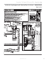
Closed Loop - External Central Pumping Applications
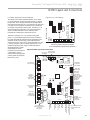
Figure 18: Typical Closed Loop with Central Pumping Application (with Internal Modulating Motorized Valve Shown)
To Thermostat
Internal Motorized
Modulating Valve
Water Out
Water In
High and
Low Voltage
Knockouts
Shut Off
Ball Valves
for Isolation
Vibration Isolation Pad
Tranquility® Digital packaged units are available with a
modulating water valve option for closed-loop applications
with external central pumping (designated by a 5 in the 11th
position of the unit model number). With this option, the
Modulating Valve is regulated by the Communicating DXM2
board based on entering and leaving water temperature (∆T).
The DXM2 board outputs a 0-10v signal to determine valve
position (flow rate). The modulating valve defaults to closed
position if it loses signal but still has 24V power running to
it. If the motorized modulating valve loses both signal from
the DXM2 board AND 24V power, it will remain in the same
position it was in when it lost 24V power.
Note: The Cv (flow coefficient) of the valve used in these
units is DIFFERENT that the Cv of the valve used in the
open loop unit. It is not advisable for use in open loop
applications as sound/noise issues may result. Units with
the water circuit for closed loop, central pumping option are
only available with a copper water coil.
while turning the handle to the open position as shown in
Figure 19. This fully opens the valve for flushing. Once
flushing is complete, press the lock release again and return
the valve handle to its normally closed position.
Figure 19: Internal Modulating Motorized
Valve Positions
Sizes 026-049
Closed
Closed
Open
Open
/RFN5HOHDVH
To manually open the internal modulating motorized water
valve in TE026 – 049 push down on the handle to unlock
it. Then rotate the handle to the open position as shown
in Figure 19. This fully opens the valve for flushing. Once
flushing is complete, return the valve handle to its normally
closed position.
To manually open the internal modulating motorized water
valve in TE064 – 072, push down on the lock release button
20
Sizes 064-072
Geothermal Heat Pump Systems
Tranquility ® 30 Digital (TE) Series IOM - 60Hz HFC-410A
R e v. : 2 7 F e b . , 2 0 1 3 B
Open Loop or Ground-Water Heat Pump Applications
flushing is complete, press the lock release again and return
the valve handle to its normally closed position.
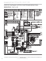
Figure 20: Typical Open Loop/Well Application
To Thermostat
Internal Motorized
Modulating Valve
Pressure
Tank
Water Out
Water In
High and
Low Voltage
Knockouts
Boiler
Drains
Shut Off
Ball Valves
for Isolation
Optional
Filter
Vibration Isolation Pad
CAUTION!
CAUTION! Refrigerant pressure activated water regulating
valves should never be used with this equipment.
Tranquility® packaged units are available with a water circuit
option for open loop applications (designated by a 6 in the
11th position of the unit model number).
The Motorized Modulating Valve is regulated by the
Communicating DXM2 board based on entering and leaving
water temperature (∆T). The DXM2 board gives a 0-10v
signal to determine flow rate. The motorized modulating
valve defaults to closed position if it loses signal but still
has 24V power running to it. If the motorized modulating
valve loses both signal from the DXM2 board AND 24V
power, it will remain in the same position it was in when it
lost 24V power. DO NOT USE open loop units in closed loop
applications due to significant pressure drop through the
open loop motorized modulating valve. This option is only
available with Cupro-Nickel Water Coil.
To manually open the internal modulating motorized water
valve in TE026 – 049 push down on the handle to unlock
it. Then rotate the handle to the open position as shown
in Figure 19. This fully opens the valve for flushing. Once
flushing is complete, return the valve handle to its normally
closed position.
To manually open the internal modulating motorized water
valve in TE064 – 072, push down on the lock release button
while turning the handle to the open position as shown in
Figure 19. This fully opens the valve for flushing. Once
Open Loop - Ground Water Systems
Typical open loop piping is shown in Figure 20. Shut off valves
should be included for ease of servicing. Boiler drains or other
valves should be “tee’d” into the lines to allow acid flushing
of the heat exchanger. Shut off valves should be positioned
to allow flow through the coax via the boiler drains without
allowing flow into the piping system. Schrader ports built into
unit may be used to measure heat exchanger pressure drop.
Water temperature can be viewed on the communicating
thermostat. Piping materials should be limited to copper, PE,
or PVC SCH80. Note: Due to the pressure and temperature
extremes, PVC SCH40 is not recommended.
Water quantity should be plentiful and of good quality. Consult
Table 5 for water quality requirements. vFlow™ units for open
loop applications always come with Cupro-Nickel coils. In
ground water situations where scaling could be heavy or
where biological growth such as iron bacteria will be present,
an open loop system is not recommended. Heat exchanger
coils may over time lose heat exchange capabilities due to
build up of mineral deposits. Heat exchangers must only
be serviced by a qualified technician, as acid and special
pumping equipment is required. Desuperheater coils can
likewise become scaled and possibly plugged. In areas with
extremely hard water, the owner should be informed that the
heat exchanger may require occasional acid flushing. In some
cases, the desuperheater option should not be recommended
due to hard water conditions and additional maintenance
required.
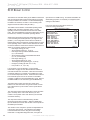
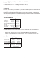
Water Quality Standards
Table 5 should be consulted for water quality requirements.
Scaling potential should be assessed using the pH/Calcium
hardness method. If the pH <7.5 and the Calcium hardness
is less than 100 ppm, scaling potential is low. If this method
yields numbers out of range of those listed, a monitoring plan
should be implemented in these probable scaling situations.
Other water quality issues such as iron fouling, corrosion
prevention and erosion and clogging should be referenced in
Table 5.
Pressure Tank and Pump
Use a closed, bladder-type pressure tank to minimize
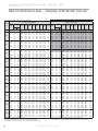
mineral formation due to air exposure. The pressure tank
should be sized to provide at least one minute continuous
run time of the pump using its drawdown capacity rating to
prevent pump short cycling. Discharge water from the unit
is not contaminated in any manner and can be disposed
of in various ways, depending on local building codes (e.g.
recharge well, storm sewer, drain field, adjacent stream
or pond, etc.). Most local codes forbid the use of sanitary
sewer for disposal. Consult your local building and zoning
department to assure compliance in your area.
c l i m a t e m a s t e r. c o m
21
Tranquility ® 30 Digital (TE) Series IOM - 60Hz HFC-410A
R e v. : 2 7 F e b . , 2 0 1 3 B
Open Loop or Ground-Water Heat Pump Applications
The pump should be sized to handle the home’s domestic
water load (typically 5-9 gpm [23-41 l/m]) plus the flow rate
required for the heat pump. Pump sizing and expansion
tank must be chosen as complimentary items. For example,
an expansion tank that is too small can cause premature
pump failure due to short cycling. Variable speed pumping
applications should be considered for the inherent energy
savings and smaller pressure tank requirements.
22
Water Coil Low Temperature Limit Setting
For all open loop systems the 30°F [-1.1°C] LT1 setting
(factory setting-water) should be used to avoid freeze
damage to the unit. See “Low Water Temperature Cutout
Selection” (Figure 17) in this manual for details on the low
limit setting.
Geothermal Heat Pump Systems
Tranquility ® 30 Digital (TE) Series IOM - 60Hz HFC-410A
R e v. : 2 7 F e b . , 2 0 1 3 B
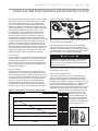
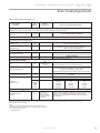
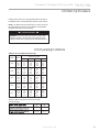
Water Quality Requirements
Table 5: Water Quality Requirements
Water Quality
Parameter
HX
Material
Closed
Recirculating
Open Loop and Recirculating Well
Scaling Potential - Primary Measurement
Above the given limits, scaling is likely to occur. Scaling indexes should be calculated using the limits below
pH/Calcium Hardness
Method
All
-
pH < 7.5 and Ca Hardness <100ppm
Index Limits for Probable Scaling Situations - (Operation outside these limits is not recommended)
Scaling indexes should be calculated at 66°C for direct use and HWG applications, and at 32°C for indirect HX use.
A monitoring plan should be implemented.
Ryznar
6.0 - 7.5
All
Stability Index
If >7.5 minimize steel pipe use.
-0.5 to +0.5
Langelier
All
If <-0.5 minimize steel pipe use. Based upon 66°C HWG and
Saturation Index
Direct well, 29°C Indirect Well HX
Iron Fouling
Iron Fe 2+ (Ferrous)
(Bacterial Iron potential)
All
Iron Fouling
All
-
<0.2 ppm (Ferrous)
If Fe2+ (ferrous)>0.2 ppm with pH 6 - 8, O2<5 ppm check for iron bacteria.
-
<0.5 ppm of Oxygen
Above this level deposition will occur .
Corrosion Prevention
6 - 8.5
pH
All
Hydrogen Sulfide (H2S)
All
Ammonia ion as hydroxide, chloride,
nitrate and sulfate compounds
All
Monitor/treat as
needed
-
6 - 8.5
Minimize steel pipe below 7 and no open tanks with pH <8
<0.5 ppm
At H2S>0.2 ppm, avoid use of copper and copper nickel piping or HX's.
Rotten egg smell appears at 0.5 ppm level.
Copper alloy (bronze or brass) cast components are OK to <0.5 ppm.
-
<0.5 ppm
Maximum Allowable at maximum water temperature.
Maximum
Chloride Levels
Copper
Cupronickel
304 SS
316 SS
Titanium
-
10$C
<20ppm
<150 ppm
<400 ppm
<1000 ppm
>1000 ppm
24$C
NR
NR
<250 ppm
<550 ppm
>550 ppm
38 C
NR
NR
<150 ppm
< 375 ppm
>375 ppm
Erosion and Clogging
Particulate Size and
Erosion
All
<10 ppm of particles
and a maximum
velocity of 1.8 m/s
Filtered for maximum
841 micron [0.84 mm,
20 mesh] size.
<10 ppm (<1 ppm "sandfree” for reinjection) of particles and a maximum
velocity of 1.8 m/s. Filtered for maximum 841 micron 0.84 mm,
20 mesh] size. Any particulate that is not removed can potentially
clog components.
The ClimateMaster Water Quality Table provides water quality requirements for ClimateMaster coaxial heat exchangers. When water properties are outside of those
requirements, an external secondary heat exchanger must be used to isolate the heat pump heat exchanger from the unsuitable water. Failure to do so will void the
warranty for the coaxial heat exchanger.
Rev.: 3/22/2012
Notes:
&ORVHG5HFLUFXODWLQJV\VWHPLVLGHQWLILHGE\Dclosed pressurized piping system.
5HFLUFXODWLQJRSHQZHOOVVKRXOGREVHUYHWKHRSHQUHFLUFXODWLQJGHVLJQFRQVLGHUDWLRQV
15Application not recommended.
1RGHVLJQ0D[LPXP
c l i m a t e m a s t e r. c o m
23
Tranquility ® 30 Digital (TE) Series IOM - 60Hz HFC-410A
R e v. : 2 7 F e b . , 2 0 1 3 B
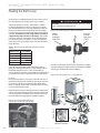
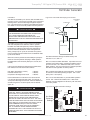
Hot Water Generator
The HWG (Hot Water Generator) or desuperheater option
provides considerable operating cost savings by utilizing
heat energy from the compressor discharge line to help
satisfy domestic hot water requirements. The HWG is active
throughout the year, providing virtually free hot water when
the heat pump operates in the cooling mode or hot water at
the COP of the heat pump during operation in the heating
mode. Actual HWG water heating capacities are provided in
the appropriate heat pump performance data.
It is always advisable to use water softening equipment on
domestic water systems to reduce the scaling potential and
lengthen equipment life. In extreme water conditions, it may
be necessary to avoid the use of the HWG option since the
potential cost of frequent maintenance may offset or exceed
any savings. Consult Table 5 for scaling potential tests.
Figure 21: Typical HWG Installation
Heat pumps equipped with the HWG option include a builtin water to refrigerant heat exchanger that eliminates the
need to tie into the heat pump refrigerant circuit in the field.
The control circuit and pump are also built in for residential
equipment. Figure 21 shows a typical example of HWG water
piping connections on a unit with built-in circulating pump.
This piping layout prevents sludge/debris from the bottom of
the tank being pulled into the HWG pump.
Hot Outlet
to home
Shut Off
Valve #1
Shut Off
Valve #4
Upper
element to
120 - 130°F
[49 - 54°C]
Lower
element to
100 - 110°F
[38 - 43°C]
Powered
Water
Heater
Shut-off
Valve #3
The temperature set point of the HWG is field selectable
to 125°F or 150°F . The 150°F set point allows more heat
storage from the HWG. For example, consider the amount
of heat that can be stored by the HWG when using the 125°F
set point, versus the amount of heat that can be generated
by the HWG when using the 150°F set point.
In a typical 50 gallon two-element electric water heater
the lower element should be turned down to 100°F, or the
lowest setting, to get the most from the HWG. The tank will
eventually stratify so that the lower 80% of the tank, or 40
gallons, becomes 100°F (controlled by the lower element).
The upper 20% of the tank, or 10 gallons, will be maintained
at 125°F (controlled by the upper element).
Cold
Inlet
Shut Off
Valve #2
Field supplied 3/4’ brass nipple and ‘T’
Insulated water lines 5/8” OD, 50 ft maximum (one way)
[16mm OD, 15 meters maximum]
Figure 22: HWG Double Tank Installation
Hot Outlet to
house
Cold Inlet
Cold Inlet from
Domestic supply
Hot Outlet
Using a 125°F set point, the HWG can heat the lower 40
gallons of water from 100°F to 125°F, providing up to 8,330
btu’s of heat. Using the 150°F set point, the HWG can heat
the same 40 gallons of water from 100°F to 150°F and the
remaining 10 gallons of water from 125°F to 150°F, providing
a total of up to 18,743 btu’s of heat, or more than twice as
much heat as when using the 125°F set point.
Electric water heaters are recommended. If a gas, propane,
or oil water heater is used, a second preheat tank must be
installed (Figure 22). If the electric water heater has only a
single center element, the dual tank system is recommended
to insure a usable entering water temperature for the HWG.
Typically a single tank of at least 50 gallons (189 liters) is used
to limit installation costs and space. However, a dual tank, as
shown in Figure 22, is the preferred system, as it provides the
maximum storage and temperate source water to the HWG.
WARNING!
WARNING! A 150°F SETPOINT MAY LEAD TO
SCALDING OR BURNS. THE 150°F SET POINT MUST
ONLY BE USED ON SYSTEMS THAT EMPLOY AN
APPROVED ANTI-SCALD VALVE.
24
Geothermal Heat Pump Systems
Shut-off
Valve #1
Upper element to 130°F [54°C]
(or owner preference)
Shut-off
Valve #4
Powered
Water Heater
Lower element to 120°F [49°C]
Unpowered
Shut-off
Valve #3
Water Heater
Shut Off
Valve #2
Field Supplied 3/4” brass nipple and “T”
Insulated water lines - 5/8” OD, 50 ft maximum (one way)
[16mm OD, 15 meters maximum]
Tranquility ® 30 Digital (TE) Series IOM - 60Hz HFC-410A
R e v. : 2 7 F e b . , 2 0 1 3 B
Hot Water Generator
Installation
The HWG is controlled by two sensors and the DXM2 microprocessor control. One sensor is located on the compressor
discharge line to sense the discharge refrigerant temperature. The other sensor is located on the HWG heat exchanger’s “Water In” line to sense the potable water temperature.
Figure 23: Anti-Scald Valve Piping Connections
ANTI-SCALD
COLD WATER
VALVE PIPING
SUPPLY
CONNECTIONS
CHECK VALVE
ANTI-SCALD
VALVE
WARNING!
C
HOT WATER
TO HOUSE
M
H
8” MAX
WARNING! UNDER NO CIRCUMSTANCES SHOULD
THE SENSORS BE DISCONNECTED OR REMOVED.
FULL LOAD CONDITIONS CAN DRIVE HOT
WATER TANK TEMPERATURES FAR ABOVE SAFE
TEMPERATURE LEVELS IF SENSORS DISCONNECTED
OR REMOVED.
The DXM2 microprocessor control monitors the refrigerant
and water temperatures to determine when to operate
the HWG. The HWG will operate any time the refrigerant
temperature is sufficiently above the water temperature.
Once the HWG has satisfied the water heating demand
during a heat pump run cycle, the controller will cycle the
pump at regular Intervals to determine if an additional HWG
cycle can be utilized.
When the control is powered and the HWG pump output is
active for water temperature sampling or HWG operation,
the DXM2 status LED will slowly flash (On 1 second, Off 1
second).
WATER HEATER
Hot Water Generator settings are determined by DIP
switches 3-2, 3-3, and 3-4.
If the control has detected a HWG fault, the DXM2 status
LED will flash a numeric fault code as follows:
DIP 3-2 controls the HWG Test Mode. It provides for forced
operation of the HWG output, activating the HWG pump for
up to five minutes. ON = HWG test mode, OFF = normal
HWG operation. The control will revert to standard operation
after five minutes regardless of switch position.
High Water Temperature (>160ºF)
Hot Water Sensor Fault
Compressor Discharge Sensor Fault
DIP 3-3 determines HWG set point temperature. It provides
for selection of the HWG operating set point. ON = 150°F
(66°C), OFF = 125°F (52°C).
5 flashes
6 flashes
6 flashes
Fault code flashes have a duration of 0.3 seconds with
a 10 second pause between fault codes. For example, a
“Compressor Discharge sensor fault” will be six flashes 0.3
seconds long, then a 10 second pause, then six flashes
again, etc.
DIP 3-4 is for the HWG status. It provides HWG operation
control. ON = HWG mode enabled, OFF = HWG mode
disabled. Units are shipped from the factory with this switch
in the OFF position.
Figure 24: Hot Water Generator Settings
WARNING!
Gnd
NC
P2
AL2
R
NSB
C
Alarm
Relay
Micro
U1
JW1
1
HP
HP
LP
LP
LT1
LT1
LT2
LT2
RV
RV
CO
12 CO
Fault Status
ESD
OVR
H
On
JW3
Off
On
R
NO1
NC1
COM1
NO2
NC2
COM2
R
Acc1
Relay
On
1 2 3 4 5 6 7 8
S3
P3
Off
1 2 3 4 5 6 7 8
c l i m a t e m a s t e r. c o m
Off
A
1 2 3 4
Hot Water
Generator
Settings
Factory Use
WARNING! USING A 150°F SETPOINT ON THE
HWG WILL RESULT IN WATER TEMPERATURES
SUFFICIENT TO CAUSE SEVERE PHYSICAL INJURY
IN THE FORM OF SCALDING OR BURNS, EVEN
WHEN THE HOT WATER TANK TEMPERATURE
SETTING IS VISIBLY SET BELOW 150°F. THE 150°F
HWG SETPOINT MUST ONLY BE USED ON SYSTEMS
THAT EMPLOY AN APPROVED ANTI-SCALD VALVE
(PART NUMBER AVAS4) AT THE HOT WATER
STORAGE TANK WITH SUCH VALVE PROPERLY
SET TO CONTROL WATER TEMPERATURES
DISTRIBUTED TO ALL HOT WATER OUTLETS AT A
TEMPERATURE LEVEL THAT PREVENTS SCALDING
OR BURNS!
P7
RV
Relay
CCH
Relay
1 24Vdc
S2
A0-1 A0-2
S1
EH1
4 EH2
Comp
Relay
P6
CCG
Acc2
Relay
COH
P11
COM
AO2 Gnd
P10
T1 T2 T2 T3 T3 T4 T4
P9
CC
T5 T5 T6 T6
25
Tranquility ® 30 Digital (TE) Series IOM - 60Hz HFC-410A
R e v. : 2 7 F e b . , 2 0 1 3 B
Hot Water Generator
WARNING!
WARNING! The HWG pump Is fully wired from the
factory. Use extreme caution when working around
the microprocessor control as it contains line voltage
connections that presents a shock hazard that can cause
severe injury or death!
The heat pump, water piping, pump, and hot water tank
should be located where the ambient temperature does
not fall below 50°F [10°C]. Keep water piping lengths at a
minimum. DO NOT use a one way length greater than 50 ft.
(one way) [15 m]. See Table 6 for recommended piping sizes
and maximum lengths.
All installations must be in accordance with local codes. The
installer is responsible for knowing the local requirements,
and for performing the installation accordingly. DO NOT
activate the HWG (turn DIP 3-4 to the ON position) until
“Initial Start-Up” section, below is completed. Powering the
pump before all installation steps are completed will damage
the pump.
Water Tank Preparation
1. Turn off power or fuel supply to the hot water tank.
2. Connect a hose to the drain valve on the water tank.
3. Shut off the cold water supply to the water tank.
4. Open the drain valve and open the pressure relief valve
or a hot water faucet to drain tank.
5. When using an existing tank, it should be flushed with
cold water after it is drained until the water leaving the
drain hose is clear and free of sediment.
6. Close all valves and remove the drain hose.
7. Install HWG water piping.
HWG Water Piping
1. Using at least 1/2” [12.7mm] I.D. copper, route and install
the water piping and valves as shown in Figures 21 or
22. Install an approved anti-scald valve if the 150°F HWG
setpoint is or will be selected. An appropriate method
must be employed to purge air from the HWG piping.
This may be accomplished by flushing water through the
HWG (as in Figures 21 and 22) or by installing an air vent
at the high point of the HWG piping system.
2. Insulate all HWG water piping with no less than 3/8”
[10mm] wall closed cell insulation.
3. Open both shut off valves and make sure the tank drain
valve is closed.
Water Tank Refill
1. Close valve #4. Ensure that the HWG valves (valves #2
and #3) are open. Open the cold water supply (valve #1)
to fill the tank through the HWG piping. This will force
water flow through the HWG and purge air from the
HWG piping.
2. Open a hot water faucet to vent air from the system until
water flows from faucet; turn off faucet. Open valve #4.
3. Depress the hot water tank pressure relief valve handle to
26
ensure that there is no air remaining in the tank.
4. Inspect all work for leaks.
5. Before restoring power or fuel supply to the water heater,
adjust the temperature setting on the tank thermostat(s)
to insure maximum utilization of the heat available from
the refrigeration system and conserve the most energy.
On tanks with both upper and lower elements and
thermostats, the lower element should be turned down
to 100°F [38°C] or the lowest setting; the upper element
should be adjusted to 120-130°F [49-54°C]. Depending
upon the specific needs of the customer, you may want
to adjust the upper element differently. On tanks with a
single thermostat, a preheat tank should be used (Fig 21).
6. Replace access cover(s) and restore power or
fuel supply.
Initial Start-Up
1. Make sure all valves in the HWG water circuit are
fully open.
2. Turn on the heat pump and allow it to run for
10-15 minutes.
3. Set S3-4 to the “ON” position (enabled) to engage the
HWG. See Figure 24.
4. The HWG pump should not run if the compressor is not
running.
5. The temperature difference between the water entering
and leaving the HWG coil should be approximately
5-10°F [3-6°C].
6. Allow the unit to operate for 20 to 30 minutes to insure
that it is functioning properly.
Table 6: HWG Water Piping Sizes and Length
Unit
Nominal
Tonnage
Nominal
HWG Flow
(gpm)
1/2" Copper
(max length*)
3/4" Copper
(max length*)
2.0
0.8
50
-
2.5
1.0
50
-
3.0
1.2
50
-
3.5
1.4
50
-
4.0
1.6
45
50
5.0
2.0
25
50
6.0
2.4
10
50
*Maximum length is equivalent length (in feet) one way of type L copper.
CAUTION!
CAUTION! Use only copper piping for HWG piping due to
the potential of high water temperatures for water that has
been in the HWG heat exchanger during periods of no-flow
conditions (HWG pump not energized). Piping other than
copper may rupture due to high water temperature and
potable water pressure.
Geothermal Heat Pump Systems
Tranquility ® 30 Digital (TE) Series IOM - 60Hz HFC-410A
R e v. : 2 7 F e b . , 2 0 1 3 B
Electrical - Line Voltage
WARNING!
WARNING! To avoid possible injury or death due to
electrical shock, open the power supply disconnect switch
and secure it in an open position during installation.
CAUTION!
CAUTION! Use only copper conductors for field installed
electrical wiring. Unit terminals are not designed to accept
other types of conductors.
Table 7a: Tranquility 30® (TE) Series Electrical Data
Compressor
Model
HWG Fan Total Min
Pump Motor Unit Circuit
FLA
FLA FLA Amps
Max/
Fuse
HACR
RLA
LRA
Qty
026
11.7
58.3
1
038
15.8
83.0
1
0.5
3.9
19.7
23.5
35
049
21.7
104.0
1
0.5
6.9
28.6
33.9
50
064
27.1
152.9
1
0.5
6.9
34.5
41.2
60
072
29.7
179.2
1
0.5
6.9
37.1
44.5
70
0.5
3.9
Rated Voltage of 208-230/60/1
HACR circuit breaker in USA only
16.1
19.0
Compressor
30
RLA
LRA
Qty
Ext
Loop
FLA
Fan
Motor
FLA
Total
Unit
FLA
Min
Circuit
Amps
Figure 25: Tranquility Single Phase Line Voltage
Field Wiring
Max/
Fuse
HACR
026
11.7
58.3
1
0.5
1.7
3.9
17.8
20.7
30
038
15.8
83.0
1
0.5
1.7
3.9
21.4
25.2
40
049
21.7
104.0
1
0.5
1.7
6.9
30.3
35.6
50
064
27.1
152.9
1
0.5
1.7
6.9
36.2
42.9
70
072
29.7
179.2
1
0.5
1.7
6.9
38.8
46.2
70
Rated Voltage of 208-230/60/1
HACR circuit breaker in USA only
General Line Voltage Wiring
Be sure the available power is the same voltage and phase
shown on the unit serial plate. Line and low voltage wiring
must be done in accordance with local codes or the National
Electric Code, whichever is applicable.
208 Volt Operation
All residential 208-230 Volt units are factory wired for 230
Volt operation. The transformer may be switched to the 208V
tap as illustrated on the wiring diagram by switching the red
(208V) and the orange (230V) wires at the contactor terminal.
Min/Max Voltage of 197/254
All fuses Class RK-5
HWG
Pump
FLA
All final electrical connections must be made with a length of
flexible conduit to minimize vibration and sound transmission
to the building.
Power Connection
Line voltage connection is made by connecting the incoming
line voltage wires to the “L” side of the contactor as shown in
Figure 25. Consult Tables 7a through 7b for correct fuse size.
Note: always refer to the unit dataplate for unit electrical data.
Table 7b: Tranquility 30® (TE) Series Electrical Data
with Magna Inernal Flow Controller
Model
Electrical - Line Voltage
All field installed wiring, including electrical ground, must
comply with the National Electrical Code as well as all
applicable local codes. Refer to the unit electrical data for
fuse sizes. Consult wiring diagram for field connections that
must be made by the installing (or electrical) contractor.
Min/Max Voltage of 197/254
All fuses Class RK-5
WARNING!
WARNING! Disconnect electrical power source to prevent
injury or death from electrical shock.
CAUTION!
CAUTION! Use only copper conductors for field installed
electrical wiring. Unit terminals are not designed to accept
other types of conductors.
Unit Power Supply
(see electrical tables 7a - 7b for minimum
circuit amps and maximum breaker size)
c l i m a t e m a s t e r. c o m
27
Tranquility ® 30 Digital (TE) Series IOM - 60Hz HFC-410A
R e v. : 2 7 F e b . , 2 0 1 3 B
Electrical - Low Voltage Wiring
Figure 26: Tranquility Low Voltage Field Wiring
Table 9: Accessory Relay 2 Configuration
DIP 2.4
DIP 2.5
DIP 2.6
ACC2 Relay Option
ON
ON
ON
Cycle with compressor
OFF
ON
ON
N/A for Residential Applications
ON
OFF
ON
Water valve – Slow opening
OFF
OFF
ON
Humidifier
ON
ON
OFF
Outside air damper
All other DIP combinations are invalid
Figure 27: Accessory Connections
Gnd
NC
P2
AL2
R
NSB
C
Alarm
Relay
Micro
U1
JW1
1
HP
HP
LP
LP
LT1
LT1
LT2
LT2
RV
RV
CO
12 CO
Fault Status
ESD
OVR
H
Off
A
On
JW3
1 2 3 4
Accessory
Terminal
Off
On
1 2 3 4 5 6 7 8
R
NO1
COM1
NO2
NC2
COM2
R
Low Voltage Field Wiring
Accessory Connections
A terminal paralleling the compressor contactor coil
has been provided on the DXM2 control. Terminal “A” is
designed to control accessory devices. Note: This terminal
should be used only with 24 Volt signals and not line voltage.
Terminal “A” is energized with the compressor contactor (see
Figure 27).
The DXM2 controller includes two accessory relays ACC1
and ACC2. Each relay includes a normally open (NO) and
a normally closed (NC) contact. Accessory relays may be
configured to operate as shown in Tables 8 and 9.
Table 8: Accessory Relay 1 Configuration
DIP 2.1
DIP 2.2
DIP 2.3
ACC1 Relay Option
ON
ON
ON
Cycle with fan
OFF
ON
ON
N/A for Residential Applications
ON
OFF
ON
Water valve – Slow opening
ON
ON
OFF
Outside air damper
OFF
ON
OFF
ClimaDry option – Dehumidistat
OFF
OFF
OFF
ClimaDry option – Humidistat
OFF
OFF
ON
N/A for Residential Applications
ON
OFF
OFF
N/A for Residential Applications
All other DIP combinations are invalid
28
Geothermal Heat Pump Systems
Factory Use
Accessory
Relays
NC1
Acc1
Relay
On
1 2 3 4 5 6 7 8
S3
P3
Off
P7
RV
Relay
CCH
Relay
1 24Vdc
S2
A0-1 A0-2
S1
EH1
4 EH2
Comp
Relay
P6
CCG
Acc2
Relay
COH
P11
COM
AO2 Gnd
P10
T1 T2 T2 T3 T3 T4 T4
P9
T5 T5 T6 T6
CC
Tranquility ® 30 Digital (TE) Series IOM - 60Hz HFC-410A
R e v. : 2 7 F e b . , 2 0 1 3 B
Electrical - Thermostat Wiring
Thermostat Installation
The thermostat should be located on an interior wall in a
larger room, away from supply duct drafts. DO NOT locate
the thermostat in areas subject to sunlight, drafts or on
external walls. The wire access hole behind the thermostat
may in certain cases need to be sealed to prevent erroneous
temperature measurement due to air infiltration through the
wall cavity. Position the thermostat back plate against the
wall so that it appears level and so the thermostat wires
protrude through the middle of the back plate. Mark the
position of the back plate mounting holes and drill holes with
a 3/16” (5mm) bit. Install supplied anchors and secure plate
to the wall. Thermostat wire must be 18 AWG or larger wire.
Wire the appropriate thermostat as shown in Figures 28a and
28b to the low voltage terminal strip on the DXM2 control
board. Practically any heat pump thermostat will work with
these units, provided it has the correct number of heating
and cooling stages. However, using the communicating
thermostat (ATC32U**) is highly recommended for on-site,
easier configuration, monitoring and diagnosis.
CAUTION!
CAUTION! Refrigerant pressure activated water regulating
valves should never be used with ClimateMaster
equipment.
CAUTION!
CAUTION! If communicating thermostat is not installed, a
communicating service tool must be used to configure and
diagnose this system.
Fan
Figure 28a: iGate™ Communicating Thermostat
Connection to DXM2 Control
iGate™ Thermostat
ATC32U**
DXM2
24Vac Common
C
Comm +
A+
24Vac Hot
R
Comm -
B-
Gnd
A+
B24V
Outdoor
Sensor
(Optiona)
OD
GND
ID
Remote Indoor
Sensor
(Optiona)
Figure
Figure 28b:
24b: Conventional
Conventional33Heat
Heat/ /2 2Cool
CoolThermostat
Thermostat
Connection to DXM2 Control
Connection to DXM2 Control
Thermostat
Compressor
Compressor Stage 2
Y1
Auxiliary Heat
W
DH
Dehumidification
Y2
Reversing Valve
Fan
O
24Vac Hot
24Vac Common
Fault LED
R
C
G
L
DXM2
Board
Y1
Y2
W
H
O
G
R
C
AL1
Notes:
1) ECM automatic dehumidification mode operates with dehumidification airflows
in the cooling mode when the dehumidification output from thermostat is active.
Normal heating and cooling airflows are not affected.
2) DXM2 board DIP switch S2-7 must be in the auto dehumidification mode for
automatic dehumidification
3) DH connection not possible with units with internal pump. Use ATC32U**.
4) Only use ATC Communicating Thermostat when using Humidifier (H Input) with
units with internal flow controller.
Communicating
Thermostat
Or
Sensors
Diagnostic
Tool
Two-Way Communication
One-Way Communication
Or
Mot.
Modulating
Valve
Variable
Speed
Pump
c l i m a t e m a s t e r. c o m
29
Tranquility ® 30 Digital (TE) Series IOM - 60Hz HFC-410A
R e v. : 2 7 F e b . , 2 0 1 3 B
DXM2 Wiring Diagram with Internal Flow Controller - 96B0005N60
Part 1 of 2
This diagram includes typical wiring details but is not applicable to all units. For specific unit wiring, refer to the diagram or the
units’ control panel.
30
Geothermal Heat Pump Systems
Tranquility ® 30 Digital (TE) Series IOM - 60Hz HFC-410A
R e v. : 2 7 F e b . , 2 0 1 3 B
DXM2 Wiring Diagram with Internal Flow Controller - 96B0005N60
Part 2 of 2
c l i m a t e m a s t e r. c o m
31
Tranquility ® 30 Digital (TE) Series IOM - 60Hz HFC-410A
R e v. : 2 7 F e b . , 2 0 1 3 B
DXM2 Wiring Diagram with Motorized Modulating Water Valve 96B0005N62 - Part 1 of 2
This diagram includes typical wiring details but is not applicable to all units. For specific unit wiring, refer to the diagram or the
units’ control panel.
32
Geothermal Heat Pump Systems
Tranquility ® 30 Digital (TE) Series IOM - 60Hz HFC-410A
R e v. : 2 7 F e b . , 2 0 1 3 B
DXM2 Wiring Diagram with Motorized Modulating Water Valve 96B0005N62 - Part 2 of 2
c l i m a t e m a s t e r. c o m
33
Tranquility ® 30 Digital (TE) Series IOM - 60Hz HFC-410A
R e v. : 2 7 F e b . , 2 0 1 3 B
ECM Blower Control
The ECM fan is controlled directly by the DXM2 control board
that converts thermostat inputs and CFM settings to signals
used by the ECM motor controller. To take full advantage of
the ECM motor features, an iGate™ communicating multistage thermostat should be used (ATC32U**).
The DXM2 control maintains a selectable operating airflow
[CFM] for each heat pump operating mode. For each
operating mode there are maximum and minimum airflow
limits. See the ECM Blower Performance table (Table 10) for
the maximum, minimum, and default operating airflows.
Airflow levels are selected using the configuration menus of
a communicating thermostat (ATC32U**) or diagnostic tool
(ACDU**). The configuration menus allow the installer to
independently select and adjust the operating airflow for each
of the operating modes. Air flow can be selected in 25 CFM
increments within the minimum and maximum limits shown in
Table 10. The blower operating modes include:
• First Stage Cooling (Y1 & O)
• Second Stage Cooling (Y1, Y2, & O)
• First Stage Cooling in Dehumidification Mode
(Y1, O, & Dehumid)
• Second Stage Cooling in Dehumidification Mode
(Y1, Y2, O, & Dehumid)
• First Stage Heating (Y1)
• Second Stage Heating (Y1 & Y2)
• Third Stage (Auxiliary) Heating (Y1, Y2, & W)
• Emergency Heating (W with no Y1 or Y2)
• Fan (G with no Y1, Y2, or W)
Special Note for AHRI Testing: To achieve rated airflow for
AHRI testing purposes, it is necessary to change the CFM
settings to rated airflow.
Figure 29: Airflow Configuration Screen on
Communicating Thermostat
AIRFLOW SELECTION
HEAT STAGE 1
HEAT STAGE 2
AUXILIARY HEAT
EMERGENCY HEAT
COOL STAGE 1
COOL STAGE 2
COOL DEHUMID 1
COOL DEHUMID 2
CONTINUOUS FAN
HEAT OFF DELAY
COOL OFF DELAY
PREVIOUS
It is necessary to use the ATC32U** communicating
thermostat to engage the Auto Dehumidification feature on
units with Internal Flow Controllers. Units with Internal Flow
Controllers utilize the ‘H’ terminal on the DXM2 as an input
for an ambient temperature switch. Units without the Internal
Flow Controller option use the ‘H’ terminal on the DXM2
controller to initiate the Auto Dehumidification mode. Refer to
the DXM2 AOM for more information (part #97B0003N15).
The ECM motor includes “soft start” and “ramp down”
features. The soft start feature is a gentle increase of motor
rpm at blower start up. This creates a much quieter blower
start cycle.
The ramp down feature allows the blower to slowly decrease
rpm to a full stop at the end of each blower cycle. This
creates a much quieter end to each blower cycle and adds
overall unit efficiency.
The ramp down feature is eliminated during an ESD
(Emergency Shut Down) situation. When the DXM2 ESD
input is activated, the blower and all other control outputs are
immediately de-activated.
The duration of the “ramp down” periods are adjustable from
0 seconds to 255 seconds. This adjustment is available
in the Aiflow Selection screen using the communicating
thermostat or configuration/diagnostics tool, see Figure 29.
34
Geothermal Heat Pump Systems
CFM
600
750
850
850
525
700
425
550
350
60
30
NEXT
Tranquility ® 30 Digital (TE) Series IOM - 60Hz HFC-410A
R e v. : 2 7 F e b . , 2 0 1 3 B
ECM Blower Performance Data
Table 10: Tranquility® 30 (TE) Series ECM Blower Performance Data Table
Airflow in CFM with wet coil and clean air filter
Cooling Mode
Dehumid Mode
Heating Mode
Stg 2
Stg 2
Stg 2
Model
Max
ESP
(in. wg)
Fan
Motor
(hp)
Range
Default
700
525
550
425
750
600
350
850
026
1.0
1/2
Maximum
1000
800
800
600
1000
850
1000
1000
038
049
064
072
0.9
1.0
0.7
0.7
1/2
1
1
1
Stg 1
Stg 1
Stg 1
Fan
Only
Mode
Aux/
Emerg
Mode
Minimum
600
450
550
400
600
450
300
700
Default
1050
800
850
650
1100
850
550
1350
Maximum
1500
1100
1200
900
1500
1100
1500
1500
Minimum
900
600
825
550
900
600
450
1350
Default
1400
1050
1100
850
1500
1150
700
1500
Maximum
2000
1500
1600
1200
2000
1500
2000
2000
Minimum
1200
900
1100
825
1200
900
600
1350
Default
1750
1300
1400
1050
1875
1450
875
1875
Maximum
2300
1900
2000
1500
2300
1900
2300
2300
Minimum
1500
1100
1375
1000
1500
1100
750
1500
Default
1900
1450
1650
1250
2000
1650
950
2000
Maximum
2300
2200
2000
1800
2300
2200
2300
2300
Minimum
1800
1350
1650
1250
1800
1350
900
1800
Airflow is controlled within 5% up to the Max ESP shown with wet coil
c l i m a t e m a s t e r. c o m
35
Tranquility ® 30 Digital (TE) Series IOM - 60Hz HFC-410A
R e v. : 2 7 F e b . , 2 0 1 3 B
DXM2 Controls
DXM2 iGate™ Controller DXM2 is the next generation in
controls and is capable of 2-way communication with smart
components, like the communicating iGate™ thermostat,
ECM fan motor, Magna Variable-Speed Pump and
configuration/diagnostic tool.
DIP Switches – There’s no need to change the DIP switches
settings on Residential units. All DIP switches in S1 and S2
should be “on”. In S3, S3-1 should be “on” and the rest should
be “off”. For more details on DIP switches, refer to the DXM2
AOM (part # 97B0003N15).
For most residential applications, configuration, monitoring and
diagnostics can all be done from the thermostat/ service tool
so there’s no need to read LEDs and change DIP switches.
For details on user settings, refer to iGate™ Communicating
Thermostat User Manual (part # 97B0055N02).
DXM2 Control Start-up Operation
The control will not operate until all inputs and safety controls
are checked for normal conditions. The compressor will have a
5 minute anti-short cycle delay at power-up. The first time after
power-up that there is a call for compressor, the compressor
will follow a 5 to 80 second random start delay.
For details on Installer settings (not to be used by
consumers), refer to iGate™ Communicating Thermostat
Installer manual (part # 97B0055N03).
After the random start delay and anti-short cycle delay,
the compressor relay will be energized. On all subsequent
compressor calls, the random start delay is omitted.
For details on installer/service settings on the iGate™
configuration/diagnostic tool, refer to operation manual (part
# 97B0106N01).
Test Mode Button
Test mode allows the service technician to check the operation
of the control in a timely manner. By momentarily pressing the
TEST push button, the DXM2 control enters a 20 minute test
mode period in which all time delays are sped up 15 times.
For further details on the DXM2 control, refer to the DXM2
Application, Operation and Maintenance Manual (part #
97B0003N15). The DXM2 AOM is shipped with each unit.
Thermostat compatibility
It is strongly recommended that iGate™ communicating
thermostat (ATC32U**) or iGate™ configuration/ diagnostic
tool (ACDU**) be used with DXM2 control, to ensure easy
configuration, monitoring and diagnostics, in PLAIN English.
For example, Airflow CAN NOT be configured without either
the communicating thermostat or configuration/ diagnostic
tool
Field Hardware Configuration Options - Note: In the
following field hardware configuration options, changes
should be made ONLY when power is removed from the
DXM2 control.
Figure 30: Test Mode Button
Gnd B-
N.C.
N.O.
N.O.
Fan Enable
Pust test button to
enter Test Mode and
speed-up timing and
delays for 20 minutes.
Fan Speed
P8
Test
12V
IN
OUT
Gnd
NC
P12
Table 11: Unit Operation
A0-2: Configure Modulating Valve or Variable-Speed
Pump (Internal water flow Models Only)
1
CAUTION!
36
(240Vac)
(240Vac)
Com
Not Clipped = 30°F [-1°C]. Clipped = 10°F [-12°C].
CAUTION! Do not restart units without inspection and
remedy of faulting condition. Equipment damage may occur.
P4
P5
Water coil low temperature limit setting: Jumper 3 (JW3LT1 Low Temp) provides field selection of temperature limit
setting for LT1 of 30°F or 10°F [-1°F or -12°C] (refrigerant
temperature).
A0-2 jumper (Figure 32) Factory Set to “IOV” if using Internal
Modulating Motorized Valve or “PMW” if using Internal
Variable-Speed Pump. This applies only to units with Internal
Water Flow Control.
A+ 24V
2
Conventional
T-stat signal
(Non-Communicating)
Unit
ECM fan
G
Fan only
G, Y1
Stage 1 heating
1
G, Y1, Y2
Stage 2 heating
1
G, Y1, Y2, W
Stage 3 heating
G, W
Emergency heat
G, Y1, O
Stage 1 cooling
2
G, Y1, Y2, O
Stage 2 cooling
2
1
Stage 1 = 1st stage compressor, 1st stage fan operation
Stage 2 = 2nd stage compressor, 2nd stage fan operation
Stage 3 = 2nd stage compressor, auxiliary electric heat, 3rd
stage fan operation
Stage 1 = 1st stage compressor, 1st stage fan operation,
reversing valve
Stage 2 = 2nd stage compressor, 2nd stage fan operation,
reversing valve
Geothermal Heat Pump Systems
Tranquility ® 30 Digital (TE) Series IOM - 60Hz HFC-410A
R e v. : 2 7 F e b . , 2 0 1 3 B
DXM2 Layout and Connections
Figure 31: LT1 Limit Setting
Low Water Temperature Cutout Selection
The DXM2 control allows the field selection of low water
(or water-antifreeze solution) temperature limit by clipping
jumper JW3, which changes the fault cutout temperature
associated with thermistor LT1. Note that the LT1 thermistor
is located on the refrigerant line between the coaxial heat
exchanger and expansion device (TXV). Therefore, LT1 is
sensing refrigerant temperature, not water temperature,
which is a better indication of how water flow rate/
temperature is affecting the refrigeration circuit.
Off
LT2
LT2
RV
RV
CO
12 CO
On
1 2 3 4
JW3
Off
On
1 2 3 4 5 6 7 8
S3
Off
On
1 2 3 4 5 6 7 8
c1
ay
P7
RV
Relay
CCH
Relay
1 24Vdc
S2
A0-1 A0-2
EH1
4 EH2
S1
P6
Comp
Relay
CCG
c2
The factory setting for LT1 is for systems using water
ay
CC
(30°F [-1.1°C] refrigerant temperature cutout or fallout). In
P10
P9
P11
low water temperature (extended range) applications with
T5 T5 T6 T6
AO2 Gnd T1 T2 T2 T3 T3 T4 T4
antifreeze (most ground loops), jumper JW3 should be
clipped as shown in Figure 31 to change the setting to 10°F
DXM2 PCB
[-12.2°C] refrigerant cutout or fallout temperature, a more
JW3-LT1 jumper should be clipped
suitable temperature when using an antifreeze solution.
for
low temperature (antifreeze) operation
All residential units include
water/refrigerant circuit
Figure 32: DXM2 Layout and Connections
insulation to prevent internal
Service tool Communicating
condensation, which is
connection stat connection
required when operating with
entering water temperatures
P4
C
Gnd B- A+ 24V
(240Vac)
below 59°F [15°C].
(240Vac)
P1
N.O.
Com
Y2
Conventional
stat connection
N.C.
N.O.
P5
R
Y1
Fan Enable
Fan Speed
W
O
G
P8
R
Test
C
12V
IN
OUT
Gnd
NC
P12
AL1
P2
AL2
R
Cabinet
temperature
sensor
(with variable
speed pump)
NSB
C
Alarm
Relay
Micro
U1
JW1
1
HP
HP
LP
LP
LT1
LT1
LT2
LT2
RV
RV
CO
12 CO
Fault Status
ESD
OVR
H
Off
A
JW3
1 2 3 4
Off
On
R
NO1
COM1
NO2
NC2
COM2
R
Factory Use
Accessory
relays refer
to DXM2 AOM
for configuration
NC1
Acc1
Relay
On
1 2 3 4 5 6 7 8
S3
P3
Off
1 2 3 4 5 6 7 8
Communications
and HWG
Settings
On
1 24Vdc
S2
A0-1 A0-2
AO2 Gnd
P10
P9
T1 T2 T2 T3 T3 T4 T4
CC
Configure
modulating valve
or variable
speed pump
T5 T5 T6 T6
Compressor Discharge
temperature
Entering Hot water
Temperature
Leaving
air temp
Leaving
water temp
c l i m a t e m a s t e r. c o m
Electric heat
connection
P6
Comp
Relay
Entering
water temp
Variable
speed pump
24V to compressor
second-stage solenoid
for Y2/full
load capacity
Factory low
voltage molex
connection for
unit harness
EH1
Acc2
Relay
P11
Water Coil
Low Temp
Limit Setting.
JWT-LT1 jumper
should be clipped
for low temp
(antifreeze)
operation
4 EH2
CCG
COH
ECM Motor
Connection
P7
RV
Relay
CCH
Relay
S1
COM
Test Button
to Speed up
Time Delays
Use 4 mounting screws
#6 sheet metal screw
1” long
37
Tranquility ® 30 Digital (TE) Series IOM - 60Hz HFC-410A
R e v. : 2 7 F e b . , 2 0 1 3 B
Unit Commissioning And Operating Conditions
Operating Limits
Environment – Units are designed for indoor installation only. Never install units in areas subject to freezing or where humidity levels
could cause cabinet condensation (such as unconditioned spaces subject to 100% outside air).
Power Supply – Voltage utilization shall comply with unit data plate.
Determination of operating limits is dependent primarily upon three factors: 1) return air temperature. 2) water temperature,
and 3) ambient temperature. When any one of these factors is at minimum or maximum levels, the other two factors should be
at normal levels to insure proper unit operation. Extreme variations in temperature and humidity and/or corrosive water or air
will adversely affect unit performance, reliability, and service life. Consult Table 12a for operating limits.
Table 12a: Operating Limits
Operating Limits
Air Limits
Min. ambient air, DB
Rated ambient air, DB
Max. ambient air, DB
Min. entering air, DB/WB
Rated entering air, DB/WB
Max. entering air, DB/WB
Water Limits
Min. entering water
Normal entering water
Max. entering water
Normal Water Flow
Unit
Cooling
Heating
45ºF [7ºC]
80.6ºF [27ºC]
130ºF [54ºC]
65/45ºF [18/7ºC]
70/50ºF Reheat
80.6/66.2ºF [27/19ºC]
100/75ºF [38/24ºC]
39ºF [4ºC]
68ºF [20ºC]
85ºF [29ºC]
50ºF [10ºC]
68ºF [20ºC]
80ºF [27ºC]
20ºF [-6.7ºC]
20ºF [-6.7ºC]
50-110ºF [10-43ºC]
30-70ºF [-1 to 21ºC]
120ºF [49ºC]
120ºF [49ºC]
1.5 to 3.0 gpm / ton
[1.6 to 3.2 l/m per kW]
Commissioning Conditions
Consult Table 12b for commissioning conditions. Starting conditions vary depending upon model and are based upon the
following notes:
Notes:
1. Conditions in Table 12b are not normal or continuous operating conditions. Minimum/maximum limits are start-up
conditions to bring the building space up to occupancy temperatures. Units are not designed to operate under these
conditions on a regular basis.
2. Voltage utilization complies with AHRI Standard 110.
Table 12b: Commissioning Limits
Commissioning Limits
Air Limits
Min. ambient air, DB
Rated ambient air, DB
Max. ambient air, DB
Min. entering air, DB/WB
Rated entering air, DB/WB
Max. entering air, DB/WB
Water Limits
Min. entering water
Normal entering water
Max. entering water
Normal Water Flow
38
Unit
Cooling
Heating
45ºF [7ºC]
80.6ºF [27ºC]
130ºF [54ºC]
60ºF [16ºC]
80.6/66.2ºF [27/19ºC]
110/83ºF [43/28ºC]
39ºF [4ºC]
68ºF [20ºC]
85ºF [29ºC]
40ºF [4.5ºC]
68ºF [20ºC]
80ºF [27ºC]
20ºF [-6.7ºC]
20ºF [-6.7ºC]
50-110ºF [10-43ºC]
30-70ºF [-1 to 21ºC]
120ºF [49ºC]
120ºF [49ºC]
1.5 to 3.0 gpm / ton
[1.6 to 3.2 l/m per kW]
Geothermal Heat Pump Systems
Tranquility ® 30 Digital (TE) Series IOM - 60Hz HFC-410A
R e v. : 2 7 F e b . , 2 0 1 3 B
Unit Start-Up and Operating Conditions
Unit and System Checkout
BEFORE POWERING SYSTEM, please check the following:
UNIT CHECKOUT
Shutoff valves: Insure that all isolation valves are open.
Line voltage and wiring: Verify that voltage is within
an acceptable range for the unit and wiring and fuses/
breakers are properly sized. Verify that low voltage wiring
is complete.
Unit control transformer: Insure that transformer has the
properly selected voltage tap. Residential 208-230V units
are factory wired for 230V operation unless specified
otherwise.
Loop/water piping is complete and purged of air. Water/
piping is clean.
Antifreeze has been added if necessary.
Entering water and air: Insure that entering water and air
temperatures are within operating limits of Tables 12a
and 12b.
Low water temperature cutout: Verify that low water
temperature cut-out on the DXM2 control is properly set.
Unit fan: Manually rotate fan to verify free rotation and
insure that blower wheel is secured to the motor shaft.
Be sure to remove any shipping supports if needed.
DO NOT oil motors upon start-up. Fan motors are preoiled at the factory. Check unit fan CFM selection and
compare to design requirements.
Condensate line: Verify that condensate trap is installed
and pitched.
HWG is switched off at SW 3-4 unless piping is
completed and air has been purged from the system.
Unit air coil and filters: Insure that filter is clean and
accessible. Clean air coil of all manufacturing oils.
Unit controls: Verify that DXM2 field selection options are
properly set. Low voltage wiring is complete.
Blower CFM and Water ∆T is set on communicating
thermostats or diagnostic tool.
Service/access panels are in place.
SYSTEM CHECKOUT
System water temperature: Check water temperature
for proper range and also verify heating and cooling set
points for proper operation.
System pH: Check and adjust water pH if necessary to
maintain a level between 6 and 8.5. Proper pH promotes
system longevity (see Table 5).
System flushing: Verify that all air is purged from the
system. Air in the system can cause poor operation or
system corrosion. Water used in the system must be
potable quality initially and clean of dirt, piping slag,
and strong chemical cleaning agents. Some antifreeze
solutions may require distilled water.
Internal Flow Controller: Verify that it is purged of air and
in operating condition.
System controls: Verify that system controls function and
operate in the proper sequence.
Low water temperature cutout: Verify that low water
temperature cut-out controls are set properly
(LT1 - JW3).
Miscellaneous: Note any questionable aspects of
the installation.
CAUTION!
CAUTION! Verify that ALL water valves are open and
allow water flow prior to engaging the compressor.
Freezing of the coax or water lines can permanently
damage the heat pump.
CAUTION!
CAUTION! To avoid equipment damage, DO NOT
leave system filled in a building without heat during the
winter unless antifreeze is added to the water loop. Heat
exchangers never fully drain by themselves and will
freeze unless winterized with antifreeze.
Unit Start-up Procedure
1. Turn the thermostat fan position to “ON.” Blower should
start.
2. Turn Blower off.
3. Ensure all valves are adjusted to their full open position.
Ensure line power to the heat pump is on.
4. Room temperature should be within the minimummaximum ranges of listed in the unit IOM. During startup checks, loop water temperature entering the heat
pump should be between 30°F [-1°C] and 95°F [35°C].
5. It is recommended that water-to-air units be first started
in the cooling mode, when possible. This will allow liquid
refrigerant to flow through the filter-drier before entering
the TXV, allowing the filter-drier to catch any debris that
might be in the system before it reaches the TXV.
6. Two factors determine the operating limits of geothermal
heat pumps, (a) return air temperature, and (b) entering
water temperature. When either of the factors is at a
minimum or maximum level, the other factor must be at
normal levels to insure proper unit operation.
a. Place the unit in Manual Operation. When in manual
mode activate Y1,Y2, and O to initiate the cooling
mode. Also manually increase CFM until desired
cooling CFM is achieved. Next adjust pump speed
% until desired loop temperature difference (leaving
water temperature minus entering water temperature)
is achieved. (For modulating valve adjust valve %).
INSTALLER SETTINGS
THERMOSTAT CONFIG
SYSTEM CONFIG
ACCESSORY CONFIG
INPUT DEALER INFO
HUMIDITY CONFIG
TEMPERATURE ALGORITHM
DEMAND REDUCTION CNFG
SERVICE MODE
RESTORY DEFAULTS
ATC32U01
SELECT OPTION
PREVIOUS
c l i m a t e m a s t e r. c o m
39
Tranquility ® 30 Digital (TE) Series IOM - 60Hz HFC-410A
R e v. : 2 7 F e b . , 2 0 1 3 B
Unit Start-Up Procedure
SERVICE MODE
a. Go into Manual Mode activate Y1, and Y2 for
Heating. Also manually increase CFM until desired
heating CFM is achieved. Next adjust pump speed
% until desired loop temperature difference (entering
water temperature minus leaving water temperature)
is achieved. (For modulating valve adjust valve %).
b. Check for warm air delivery at the unit grille within a
few minutes after the unit has begun to operate.
MANUAL OPERATION
CONTROL DIAGNOSTICS
DIPSWITCH CONFIG
FAULT HISTORY
CLEAR FAULT HISTORY
SELECT OPTION
PREVIOUS
SELECT
MANUAL OPERATING MODE
Y1
Y2
W
O
G
H
DH
ECM
PUMP
TEST
COMM OUTPUT
COMM OUTPUT
COMM OUTPUT
COMM OUTPUT
COMM OUTPUT
COMM OUTPUT
COMM OUTPUT
AIRFLOW
SPEED
MODE
SELECT OPTION
PREVIOUS
OFF
OFF
OFF
OFF
OFF
OFF
OFF
0
0%
OFF
SELECT
b. Check for cool air delivery at the unit grille within a
few minutes after the unit has begun to operate.
NOTE: Units have a five minute time delay in the control
circuit that can be bypassed on the DXM2 control board
by placing the unit in the “Test” mode as shown in the unit
IOM. Check for normal air temperature drop of 15°F to 25°F
(cooling mode).
c. Verify that the compressor is on and that the water
temperature rise (cooling mode) is within normal
range.
9 - 12
20 - 26
d. Check the elevation and cleanliness of the
condensate lines. Dripping may be a sign of a
blocked line. Check that the condensate trap is filled
to provide a water seal.
e. Turn thermostat to “OFF” position. A hissing noise
indicates proper functioning of the reversing valve.
7. Allow five (5) minutes between tests for pressure to
equalize before beginning heating test.
40
NOTE: Units have a five minute time delay in the control
circuit that can be bypassed on the DXM2 control board
by placing the unit in the “Test” mode as shown in the unit
IOM. Check for normal air temperature rise of 20°F to 30°F
(heating mode).
4-8
10 - 17
c. Verify that the compressor is on and that the water
temperature fall (heating mode) is within normal
range.
e. Check for vibration, noise, and water leaks.
8. If unit fails to operate properly, perform troubleshooting
analysis (see troubleshooting section in the unit IOM).
If the check described fails to reveal the problem and
the unit still does not operate, contact a trained service
technician to insure proper diagnosis and repair of the
equipment.
9. When testing is complete, exit the Installer Menu and set
thermostat to maintain desired comfort level for normal
operation.
10. BE CERTAIN TO FILL OUT AND RETURN ALL
WARRANTY REGISTRATION PAPERWORK.
Unit performance may be verified by calculating the unit
heat of rejection and heat of extraction. Heat of Rejection
(HR) can be calculated and compared to the performance
data pages in this IOM. The formula for HR is as follows:
HR = TD x GPM x 500 (or 485 for anti-freeze solutions),
where TD is the temperature difference between the entering
and leaving water, and GPM is the flow rate in U.S. GPM
determined by comparing the unit heat exchanger pressure
drop to Table 13.
Heat of Extraction (HE) can also be calculated and compared
to the performance data pages in this IOM. The formula for
HE is as follows: HE = TD x GPM x 500 (or 485 for antifreeze solutions), where TD is the temperature difference
between the entering and leaving water, and GPM is the flow
rate in U.S. GPM determined by comparing the unit heat
exchanger pressure drop to Table 13.
Geothermal Heat Pump Systems
Tranquility ® 30 Digital (TE) Series IOM - 60Hz HFC-410A
R e v. : 2 7 F e b . , 2 0 1 3 B
Unit Start-Up Procedure
If performance during any mode appears abnormal, refer to
the DXM2 section or troubleshooting section of this manual.
NOTE: To obtain maximum performance, the air coil should
be cleaned before start-up. A 10% solution of dishwasher
detergent and water is recommended.
WARNING!
WARNING! When the disconnect switch is closed, high
voltage is present in some areas of the electrical panel.
Exercise caution when working with energized equipment.
Unit Operating Conditions
Table 13: TE Coax Water Pressure Drop
Model
GPM
Pressure Drop (psi)
30°F
50°F
70°F
90°F
026
4.0
6.0
7.0
8.0
1.5
3.1
4.1
5.1
1.3
2.6
3.4
4.3
1.1
2.3
3.0
3.8
1.0
2.1
2.7
3.4
038
4.0
6.0
8.0
9.0
1.2
2.6
4.5
5.7
1.0
2.5
4.2
5.2
0.8
2.3
4.0
4.8
0.6
2.1
3.7
4.4
049
5.5
8.3
11.0
12.0
1.1
2.2
3.9
4.5
0.9
2.1
3.6
4.2
0.8
2.0
3.2
3.8
0.7
1.8
3.1
3.5
064
7.0
10.5
14.0
15.0
0.5
1.9
3.9
4.8
0.3
1.8
3.5
4.3
0.2
1.7
3.2
3.9
0.1
1.6
2.9
3.5
072
7.5
11.3
15.0
17.0
1.7
3.9
6.9
8.9
1.5
3.4
6.0
7.7
1.3
3.0
5.4
6.9
1.3
2.8
5.0
6.5
Table 14: Water Temperature Change Through
Heat Exchanger
9 - 12
4-8
20 - 26
10 - 17
c l i m a t e m a s t e r. c o m
41
Tranquility ® 30 Digital (TE) Series IOM - 60Hz HFC-410A
R e v. : 2 7 F e b . , 2 0 1 3 B
Unit Operating Conditions - TE
Table 15: TE Series Typical Unit Operating Pressures and Temperatures
TE026
Full Load Cooling - without HWG active
Entering
Water
Suction
Water
Flow
Pressure
Temp
GPM/ton
PSIG
°F
Discharge
Pressure
PSIG
Superheat
Subcooling
Water
Temp
Rise
°F
Full Load Heating - without HWG active
Air Temp
Drop °F
DB
Suction
Pressure
PSIG
Discharge
Pressure Superheat Subcooling
PSIG
Water
Temp
Drop
°F
Air
Temp
Rise °F
DB
72-83
75-85
78-88
273-293
275-295
277-297
6-11
6-11
6-11
3-8
3-8
3-8
5.9-7.9
4.2-6.2
2.7-4.7
16-22
17-23
18-24
19-25
20-26
20-26
102-112
106-116
110-120
302-322
303-323
305-325
8-12
8-12
8-12
6-11
6-11
6-11
8.9-10.9
6.7-8.7
4.5-6.5
22-28
23-29
23-29
15.7-17.7
11.6-13.6
7.6-9.6
19-25
19-25
19-25
128-138
134-144
141-151
330-350
332-352
334-354
10-15
10-15
10-15
8-13
8-13
8-13
11.3-13.3
8.5-10.5
5.8-7.8
27-34
28-35
28-35
7-12
5-10
5-10
14.9-16.9
11-13
7.2-9.2
18-24
18-24
18-24
162-172
166-176
171-181
367-387
372-392
377-397
14-19
15-20
17-22
10-15
10-15
10-15
14.4-16.4
10.8-12.8
7.1-9.1
33-41
34-42
34-42
7-12
5-10
5-10
13.9-15.9
10.2-12.2
6.5-8.5
17-23
17-23
17-23
30*
1.5
2.25
3
50
1.5
2.25
3
128-138
128-138
128-138
186-206
172-192
158-178
18-23
18-23
18-23
8-13
6-11
6-11
16.3-18.3
12.1-14.1
7.8-9.8
70
1.5
2.25
3
136-146
136-146
136-146
281-301
267-287
253-273
7-12
7-12
7-12
7-12
5-10
4-9
90
1.5
2.25
3
139-149
139-149
139-149
368-388
354-374
340-360
6-11
6-11
6-11
110
1.5
2.25
3
143-153
143-153
143-153
465-485
450-470
433-453
6-11
6-11
6-11
*Based on 15% Methanol antifreeze solution
TE038
Full Load Cooling - without HWG active
Water
Temp
Rise
°F
Entering
Water
Temp
°F
Water
Flow
GPM/ton
30*
1.5
2.25
3
50
1.5
2.25
3
129-139
128-138
128-138
225-245
211-231
197-217
15-20
15-20
15-20
10-15
9-14
9-14
21.9-23.9
16.1-18.1
10.3-12.3
70
1.5
2.25
3
136-146
135-145
135-145
302-322
283-303
265-285
9-14
9-14
9-14
13-18
12-17
12-17
90
1.5
2.25
3
140-150
140-150
140-150
390-410
369-389
349-369
7-12
8-13
8-13
110
1.5
2.25
3
145-155
145-155
145-155
488-508
467-487
447-467
7-12
8-13
8-13
Suction
Pressure
PSIG
Discharge
Pressure Superheat Subcooling
PSIG
Full Load Heating - without HWG active
Air Temp
Drop °F
DB
Suction
Pressure
PSIG
Discharge
Pressure Superheat
PSIG
Subcooling
Water
Temp
Drop
°F
Air
Temp
Rise °F
DB
69-79
73-83
76-86
293-313
297-317
300-320
7-12
7-12
7-12
14-19
14-19
14-19
8.9-10.9
6.7-8.7
4.5-6.5
17-23
18-24
19-25
18-24
19-25
19-25
96-106
100-110
105-115
322-342
326-346
331-351
10-15
10-15
10-15
17-22
17-22
17-22
12.2-14.2
9.3-11.3
6.4-8.4
23-29
24-30
24-30
21.5-23.5
15.8-17.8
10-12
18-24
19-25
19-25
123-133
129-139
135-145
352-372
358-378
364-384
11-16
11-16
11-16
19-24
19-24
19-24
15-17
11.6-13.6
8.2-10.2
28-35
29-36
30-37
13-18
8-13
8-13
20.5-22.5
14.9-16.9
9.3-11.3
17-23
17-23
17-23
157-167
169-179
181-191
390-410
399-419
408-428
13-18
13-18
14-19
18-23
16.5-21.5
15-20
21-23
15.5-17.5
10.5-12.5
36-44
37-45
39-47
13-18
8-13
8-13
19-21
14-16
9-11
17-23
17-23
17-23
Suction
Pressure
PSIG
Discharge
Pressure
PSIG
Superheat
Subcooling
Water
Temp
Drop
°F
Air
Temp
Rise °F
DB
66-76
69-79
72-82
286-306
289-309
292-312
7-12
7-12
7-12
8-13
9-14
9-14
8-10
6-8
4-6
18-24
19-25
19-25
*Based on 15% Methanol antifreeze solution
TE049
Full Load Cooling - without HWG active
Water
Temp
Rise
°F
Full Load Heating - without HWG active
Entering
Water
Temp
°F
Water
Flow
GPM/ton
30*
1.5
2.25
3
50
1.5
2.25
3
125-135
123-133
122-132
242-262
224-244
205-225
13-18
13-18
14-19
10-15
9-14
7-12
20.9-22.9
15.6-17.6
10.2-12.2
19-25
19-25
19-25
93-103
98-108
103-113
314-334
320-340
326-346
8-13
8-13
8-13
10-15
10-15
10-15
11.5-13.5
8.7-10.7
5.9-7.9
23-29
24-30
25-31
70
1.5
2.25
3
133-143
132-142
131-141
310-330
290-310
270-290
8-13
8-13
9-14
8-13
7-12
5-10
20.5-22.5
15.2-17.2
9.9-11.9
19-25
19-25
19-25
123-133
130-140
137-147
344-364
354-374
361-381
9-14
9-14
9-14
9-14
9-14
9-14
15-17
11.5-13.5
7.9-9.9
28-35
29-36
30-37
90
1.5
2.25
3
138-148
137-147
136-146
396-416
374-394
352-372
7-12
7-12
7-12
7-12
6-11
4-9
19.2-21.2
14.3-16.3
9.3-11.3
18-24
18-24
18-24
165-175
175-185
185-195
390-410
401-421
413-433
13-18
15-20
17-22
8-13
8-13
8-13
19.6-21.6
15-17
10.3-12.3
37-45
38-46
39-47
110
1.5
2.25
3
144-154
143-153
142-152
497-517
472-492
447-467
7-12
7-12
7-12
5-10
4-9
3-8
18-20
13.3-15.3
8.5-10.5
17-23
17-23
17-23
Suction
Pressure
PSIG
Discharge
Pressure Superheat
PSIG
Subcooling
Air Temp
Drop °F
DB
*Based on 15% Methanol antifreeze solution
42
Geothermal Heat Pump Systems
Tranquility ® 30 Digital (TE) Series IOM - 60Hz HFC-410A
R e v. : 2 7 F e b . , 2 0 1 3 B
Unit Operating Conditions - TE
Table 15: TE Series Typical Unit Operating Pressures and Temperatures: Continued
TE064
Entering
Water
Water
Flow
Temp
GPM/ton
°F
Full Load Cooling - without HWG active
Water
Temp
Superheat Subcooling
Rise
°F
Suction
Pressure
PSIG
Discharge
Pressure
PSIG
Air Temp
Drop °F
DB
Full Load Heating - without HWG active
Water
Temp
Drop
°F
Suction Discharge
Pressure Pressure Superheat Subcooling
PSIG
PSIG
Air
Temp
Rise °F
DB
66-76
69-79
72-82
282-302
285-305
289-309
10-16
10-16
10-16
9-14
9-14
10-15
8-10
6-8
4-6
19-25
19-25
20-26
21-27
21-27
21-27
90-100
95-105
99-109
310-330
313-333
316-336
11-17
11-17
11-17
12-17
12-17
12-17
11.3-13.3
8.5-10.5
5.7-7.7
24-30
25-31
26-32
21-23
15.5-17.5
10-12
22-28
22-28
22-28
115-125
120-130
126-136
337-357
341-361
345-365
12-18
12-18
12-18
14-19
14-19
15-20
14-16
10.6-12.6
7.3-9.3
28-35
29-36
30-37
15-20
13-18
11-16
20.1-22.1
14.8-16.8
9.5-11.5
21-27
21-27
21-27
157-167
161-171
166-176
390-410
394-414
398-418
15-20
15-20
15-20
14-19
14-19
15-20
18.2-20.2
13.9-15.9
9.6-11.6
37-45
38-46
39-47
14-19
13-18
12-17
19-21
14-16
9-11
20-26
20-26
20-26
30*
1.5
2.25
3
50
1.5
2.25
3
128-138
126-136
125-135
238-258
222-242
205-225
16-21
21-26
26-31
14-19
13-18
12-17
20.5-22.5
14.9-16.9
9.2-11.2
70
1.5
2.25
3
135-145
134-144
133-143
315-335
296-316
276-296
10-15
12-17
15-20
14-19
13-18
11-16
90
1.5
2.25
3
139-149
138-148
138-148
408-428
386-406
364-384
10-15
10-15
10-15
110
1.5
2.25
3
144-154
143-153
142-152
515-535
493-513
469-489
8-13
8-13
8-13
*Based on 15% Methanol antifreeze solution
TE072
Full Load Cooling - without HWG active
Entering Water
Flow
Water
GPM/
Temp
ton
°F
Suction Discharge
Pressure Pressure Superheat Subcooling
PSIG
PSIG
Full Load Heating - without HWG active
Water
Temp
Rise
°F
Air
Suction Discharge
Temp
Pressure Pressure Superheat Subcooling
Drop °F
PSIG
PSIG
DB
Water
Temp
Drop
°F
Air
Temp
Rise
°F DB
61-71
65-75
68-78
292-312
296-316
300-320
11-16
11-16
10-15
13-18
14-19
15-20
7.2-9.2
5.4-7.4
3.5-5.5
19-25
20-26
21-27
22-28
23-29
24-30
89-99
98-108
106-116
327-347
337-357
348-368
10-15
10-15
10-15
19-24
14-19
9-14
10.9-12.9
8.3-10.3
5.7-7.7
26-32
28-34
30-36
17.6-19.6
13.8-15.8
10-12
23-29
23-29
23-29
119-129
132-142
144-154
365-385
380-400
395-415
10-15
10-15
10-15
21-26
16-21
11-16
14.7-16.7
11.3-13.3
7.9-9.9
33-39
36-42
38-44
16-21
14-19
13-18
16.7-18.7
12.6-14.6
8.5-10.5
22-28
22-28
22-28
162-172
172-182
182-192
418-438
430-450
444-464
10-15
10-15
11-16
19-24
19-24
19-24
19.4-21.4
14.7-16.7
10.1-12.1
43-49
45-51
47-53
16-21
14-19
13-18
15.9-17.9
11.7-13.7
7.4-9
20-27
20-27
20-27
30*
1.5
2.25
3
50
1.5
2.25
3
131-141
130-140
129-139
210-230
205-225
200-220
10-15
11-16
13-18
12-17
12-17
12-17
18.5-20.5
14-16
9.5-11.5
70
1.5
2.25
3
135-145
131-141
128-138
300-320
295-315
290-310
10-15
11-16
13-18
15-20
14-19
14-19
90
1.5
2.25
3
139-149
137-147
135-145
390-410
370-390
350-370
10-15
10-15
10-15
110
1.5
2.25
3
145-155
145-155
144-154
490-510
470-490
452-472
10-15
10-15
9-14
*Based on 15% Methanol antifreeze solution
Table 16: Antifreeze Correction
Cooling
Heating
EWT 90°F
EWT 30°F
WPD
Corr. Fct.
EWT 30°F
Antifreeze Type
Antifreeze
%
Total Cap
Sens Cap
Power
Htg Cap
Power
Water
0
1.000
1.000
1.000
1.000
1.000
5
0.995
0.995
1.003
0.989
0.997
1.070
15
0.986
0.986
1.009
0.968
0.990
1.210
25
0.978
0.978
1.014
0.947
0.983
1.360
5
0.997
0.997
1.002
0.989
0.997
1.070
15
0.990
0.990
1.007
0.968
0.990
1.160
25
0.982
0.982
1.012
0.949
0.984
1.220
5
0.998
0.998
1.002
0.981
0.994
1.140
15
0.994
0.994
1.005
0.944
0.983
1.300
25
0.986
0.986
1.009
0.917
0.974
1.360
5
0.998
0.998
1.002
0.993
0.998
1.040
15
0.994
0.994
1.004
0.980
0.994
1.120
25
0.988
0.988
1.008
0.966
0.990
1.200
Propylene Glycol
Methanol
Ethanol
Ethylene Glycol
c l i m a t e m a s t e r. c o m
1.000
43
Tranquility ® 30 Digital (TE) Series IOM - 60Hz HFC-410A
R e v. : 2 7 F e b . , 2 0 1 3 B
Table 17a: Performance Data — Tranquility® 30 Model 026- Full Load
Performance capacities shown in thousands of Btuh
Antifreeze use recommended in this range. Also Clip JW3 on DXM2 board.
Cooling - EAT 80/67°F
EWT
°F
GPM
20
30
40
50
60
70
80
90
100
110
120
1.3
1.3
1.7
1.7
1.7
1.7
1.7
1.7
2.2
2.2
2.2
2.2
2.2
2.2
3.0
3.0
3.3
3.3
3.3
3.3
3.0
3.0
4.5
4.5
6.0
6.0
3.0
3.0
4.5
4.5
6.0
6.0
3.0
3.0
4.5
4.5
6.0
6.0
3.0
3.0
4.5
4.5
6.0
6.0
3.0
3.0
4.5
4.5
6.0
6.0
3.0
3.0
4.5
4.5
6.0
6.0
3.0
3.0
4.5
4.5
6.0
6.0
WPD
PSI
FT
0.5
0.5
0.5
0.5
0.5
0.5
0.5
0.5
0.5
0.5
0.5
0.5
0.5
0.5
0.7
0.7
0.8
0.8
0.8
0.8
0.7
0.7
1.3
1.3
2.0
2.0
0.6
0.6
1.2
1.2
1.9
1.9
0.7
0.7
1.2
1.2
1.8
1.8
0.7
0.7
1.2
1.2
1.8
1.8
0.7
0.7
1.2
1.2
1.8
1.8
0.7
0.7
1.1
1.1
1.7
1.7
0.5
0.5
1.0
1.0
1.7
1.7
1.1
1.1
1.1
1.1
1.1
1.1
1.1
1.1
1.2
1.2
1.2
1.2
1.2
1.2
1.6
1.6
1.9
1.9
1.9
1.9
1.5
1.5
2.9
2.9
4.7
4.7
1.5
1.5
2.7
2.7
4.4
4.4
1.5
1.5
2.7
2.7
4.2
4.2
1.6
1.6
2.7
2.7
4.1
4.1
1.6
1.6
2.7
2.7
4.1
4.1
1.5
1.5
2.6
2.6
4.0
4.0
1.2
1.2
2.4
2.4
3.9
3.9
Heating - EAT 70°F
CFM
TC
SC
kW EER
HR
LWT HWC GPM
730
850
730
850
730
850
730
850
730
850
730
850
730
850
730
850
730
850
730
850
730
850
730
850
730
850
730
850
730
850
730
850
730
850
730
850
730
850
730
850
730
850
730
850
730
850
730
850
730
850
730
850
730
850
730
850
730
850
730
850
730
850
29.0
29.5
29.0
29.5
29.0
29.5
29.0
29.5
29.0
29.5
29.0
29.5
29.0
29.5
28.7
29.2
29.0
29.5
29.0
29.5
27.5
28.0
28.4
28.9
28.8
29.3
26.1
26.6
27.1
27.6
27.6
28.1
24.6
25.0
25.7
26.1
26.2
26.7
23.0
24.5
24.1
24.5
24.6
25.1
21.5
21.8
22.5
22.9
23.0
23.4
20.0
20.3
20.9
21.3
21.4
21.8
18.7
19.0
19.5
19.8
19.9
20.2
19.8
21.3
19.8
21.3
19.8
21.3
19.8
21.3
19.8
21.3
19.8
21.3
19.8
21.3
19.7
21.2
19.8
21.3
19.8
21.3
19.2
20.7
19.6
21.1
19.8
21.3
18.7
20.1
19.1
20.5
19.3
20.7
18.0
19.4
18.5
19.9
18.7
20.1
17.4
19.2
17.8
19.2
18.0
19.4
16.9
18.1
17.2
18.5
17.4
18.7
16.4
17.7
16.7
17.9
16.8
18.1
16.2
17.4
16.3
17.5
16.4
17.6
1.13
1.17
1.13
1.17
1.13
1.17
1.13
1.17
1.13
1.17
1.13
1.17
1.13
1.17
1.15
1.20
1.13
1.17
1.13
1.17
1.28
1.33
1.19
1.23
1.14
1.18
1.42
1.47
1.32
1.37
1.27
1.31
1.58
1.64
1.47
1.52
1.41
1.46
1.76
1.70
1.64
1.70
1.58
1.63
1.95
2.02
1.82
1.89
1.76
1.82
2.17
2.25
2.03
2.10
1.96
2.03
2.41
2.50
2.26
2.34
2.18
2.26
32.8
33.4
32.8
33.4
32.8
33.4
32.8
33.4
32.8
33.4
32.8
33.4
32.8
33.4
32.7
33.3
32.8
33.4
32.8
33.4
31.9
32.5
32.5
33.1
32.7
33.4
31.0
31.6
31.6
32.3
32.0
32.6
30.0
30.6
30.7
31.3
31.0
31.7
29.0
30.3
29.7
30.3
30.0
30.6
28.1
28.7
28.7
29.3
29.0
29.6
27.4
28.0
27.8
28.5
28.1
28.7
26.9
27.5
27.2
27.8
27.3
28.0
70.0
70.0
70.0
70.0
70.0
70.0
70.0
70.0
70.0
70.0
70.0
70.0
70.0
70.0
71.8
72.2
70.0
70.0
70.0
70.0
81.3
81.7
74.4
74.7
70.9
71.1
90.7
91.1
84.1
84.3
80.7
80.9
100.0
100.4
93.6
93.9
90.3
90.6
109.4
109.8
103.2
103.5
100.0
100.2
118.8
119.2
112.8
113.0
109.7
109.9
128.3
128.7
122.4
122.6
119.4
119.6
137.9
138.3
132.1
132.3
129.1
129.3
25.7
25.2
25.7
25.2
25.7
25.2
25.7
25.2
25.7
25.2
25.7
25.2
25.7
25.2
24.9
24.4
25.7
25.2
25.7
25.2
21.5
21.1
24.0
23.5
25.3
24.8
18.4
18.0
20.6
20.2
21.8
21.4
15.6
15.3
17.5
17.2
18.5
18.2
13.1
14.5
14.7
14.5
15.6
15.3
11.0
10.8
12.3
12.1
13.1
12.8
9.2
9.0
10.3
10.1
10.9
10.7
7.7
7.6
8.6
8.5
9.1
8.9
Interpolation is permissible; extrapolation is not.
Flow is controlled to maintain minimum LWT 70° F in cooling and maximum LWT 65° F in heating.
Table does not reflect fan or pump power corrections for AHRI/ISO conditions.
For operation in the shaded areas, please see the Performance Data Selection Notes.
44
1.4
1.4
1.4
1.4
1.4
1.4
1.4
1.4
1.4
1.4
1.4
1.4
1.4
1.4
1.4
1.5
1.4
1.4
1.4
1.4
1.9
1.9
1.5
1.6
1.4
1.4
2.4
2.4
2.0
2.0
1.8
1.9
3.0
3.0
2.5
2.6
2.3
2.4
3.6
3.3
3.2
3.3
3.0
3.0
4.4
4.5
3.9
4.0
3.7
3.7
5.3
5.4
4.7
4.8
4.5
4.5
6.3
6.4
5.6
5.8
5.3
5.5
6.0
6.0
3.0
3.0
4.5
4.5
6.0
6.0
3.0
3.0
4.5
4.5
6.0
6.0
3.0
3.0
4.5
4.5
6.0
6.0
3.0
3.0
4.5
4.5
6.0
6.0
3.0
3.0
4.5
4.5
6.0
6.0
3.0
3.0
3.6
3.6
3.6
3.6
2.2
2.2
2.2
2.2
2.2
2.2
1.5
1.5
1.5
1.5
1.5
1.5
1.2
1.2
1.2
1.2
1.2
1.2
1.0
1.0
1.0
1.0
1.0
1.0
WPD
PSI
FT
3.7
3.7
1.1
1.1
2.0
2.0
3.1
3.1
0.9
0.9
1.6
1.6
2.6
2.6
0.7
0.7
1.4
1.4
2.3
2.3
0.7
0.7
1.3
1.3
2.0
2.0
0.6
0.6
1.2
1.2
1.9
1.9
0.7
0.7
0.9
0.9
0.9
0.9
0.5
0.5
0.5
0.5
0.5
0.5
0.4
0.4
0.4
0.4
0.4
0.4
0.3
0.3
0.3
0.3
0.3
0.3
0.1
0.1
0.1
0.1
0.1
0.1
8.6
8.6
2.5
2.5
4.6
4.6
7.1
7.1
2.0
2.0
3.8
3.8
6.0
6.0
1.6
1.6
3.2
3.2
5.2
5.2
1.5
1.5
2.9
2.9
4.7
4.7
1.5
1.5
2.7
2.7
4.4
4.4
1.5
1.5
2.0
2.0
2.0
2.0
1.2
1.2
1.2
1.2
1.2
1.2
1.0
1.0
1.0
1.0
1.0
1.0
0.7
0.7
0.7
0.7
0.7
0.7
0.3
0.3
0.3
0.3
0.3
0.3
CFM
HC
kW COP HE
820
950
820
950
820
950
820
950
820
950
820
950
820
950
820
950
820
950
820
950
820
950
820
950
820
950
820
950
820
950
820
950
820
950
820
950
820
950
820
950
820
950
820
950
820
950
820
950
820
950
820
950
820
950
820
950
820
950
820
950
820
950
16.4
16.6
17.8
18.1
18.6
18.9
19.0
19.3
20.4
20.7
21.3
21.7
21.9
22.2
23.1
23.4
24.3
24.6
24.9
25.3
25.9
26.3
27.3
27.7
28.1
28.5
28.8
29.2
30.4
30.8
31.2
31.7
31.6
32.1
32.5
33.0
32.5
33.0
32.5
33.0
32.5
33.0
32.5
33.0
32.5
33.0
32.5
33.0
32.5
33.0
32.5
33.0
32.5
33.0
32.5
33.0
32.5
33.0
32.5
33.0
32.5
33.0
1.49
1.44
1.51
1.47
1.53
1.48
1.53
1.49
1.56
1.51
1.57
1.53
1.58
1.53
1.60
1.55
1.62
1.57
1.64
1.59
1.65
1.60
1.68
1.63
1.69
1.64
1.70
1.65
1.73
1.68
1.75
1.70
1.76
1.70
1.77
1.72
1.77
1.72
1.77
1.72
1.77
1.72
1.77
1.72
1.77
1.72
1.77
1.72
1.77
1.72
1.77
1.72
1.77
1.72
1.77
1.72
1.77
1.72
1.77
1.72
1.77
1.72
3.2
3.4
3.5
3.6
3.6
3.7
3.6
3.8
3.8
4.0
4.0
4.2
4.0
4.2
4.2
4.4
4.4
4.6
4.5
4.7
4.6
4.8
4.8
5.0
4.9
5.1
4.9
5.2
5.1
5.4
5.2
5.5
5.3
5.5
5.4
5.6
5.4
5.6
5.4
5.6
5.4
5.6
5.4
5.6
5.4
5.6
5.4
5.6
5.4
5.6
5.4
5.6
5.4
5.6
5.4
5.6
5.4
5.6
5.4
5.6
5.4
5.6
11.3
11.7
12.7
13.1
13.4
13.8
13.8
14.2
15.0
15.5
16.0
16.5
16.5
17.0
17.6
18.1
18.7
19.3
19.3
19.9
20.2
20.8
21.6
22.2
22.3
22.9
22.9
23.6
24.4
25.1
25.3
25.9
25.6
26.3
26.4
27.1
26.4
27.1
26.4
27.1
26.4
27.1
26.4
27.1
26.4
27.1
26.4
27.1
26.4
27.1
26.4
27.1
26.4
27.1
26.4
27.1
26.4
27.1
26.4
27.1
26.4
27.1
LAT
88.5
86.2
90.1
87.6
91.0
88.4
91.5
88.8
93.0
90.1
94.1
91.1
94.7
91.6
96.0
92.8
97.4
94.0
98.1
94.7
99.2
95.6
100.8
97.0
101.7
97.8
102.5
98.5
104.3
100.0
105.3
100.9
105.7
101.3
106.7
102.1
106.7
102.1
106.7
102.1
106.7
102.1
106.7
102.1
106.7
102.1
106.7
102.1
106.7
102.1
106.7
102.1
106.7
102.1
106.7
102.1
106.7
102.1
106.7
102.1
106.7
102.1
LWT HWC
16.2
16.1
21.6
21.3
24.1
23.9
25.4
25.3
30.0
29.7
32.9
32.7
34.5
34.3
38.3
37.9
41.7
41.4
43.6
43.4
46.5
46.1
50.4
50.1
52.6
52.4
54.7
54.3
59.1
58.8
61.6
61.4
62.9
62.5
65.0
65.0
65.0
65.0
65.0
65.0
65.0
65.0
65.0
65.0
65.0
65.0
65.0
65.0
65.0
65.0
65.0
65.0
65.0
65.0
65.0
65.0
65.0
65.0
65.0
65.0
65.0
65.0
All performance is based upon the lower voltage of dual voltage rated units.
Operation at or below 40° F EWT is based on 15% methanol antifreeze solution.
See Performance correction tables for operating conditions other than those listed above.
Geothermal Heat Pump Systems
1.6
1.5
1.8
1.8
1.9
1.9
2.0
1.9
2.2
2.1
2.3
2.3
2.4
2.3
2.6
2.5
2.7
2.6
2.8
2.7
2.9
2.8
3.1
3.0
3.2
3.1
3.3
3.2
3.5
3.4
3.6
3.5
3.6
3.5
3.7
3.6
3.7
3.6
3.7
3.6
3.7
3.6
3.7
3.6
3.7
3.6
3.7
3.6
3.7
3.6
3.7
3.6
3.7
3.6
3.7
3.6
3.7
3.6
3.7
3.6
3.7
3.6
Tranquility ® 30 Digital (TE) Series IOM - 60Hz HFC-410A
R e v. : 2 7 F e b . , 2 0 1 3 B
Table 17b: Performance Data — Tranquility® 30 Model 038 - Full Load
Performance capacities shown in thousands of Btuh
Antifreeze use recommended in this range. Also Clip JW3 on DXM2 board.
Cooling - EAT 80/67°F
EWT
°F
GPM
20
30
40
50
60
70
80
90
100
110
120
2.0
2.0
2.5
2.5
2.5
2.5
2.5
2.5
3.4
3.4
3.4
3.4
3.4
3.4
4.5
4.5
5.1
5.1
5.1
5.1
4.5
4.5
6.8
6.8
9.0
9.0
4.5
4.5
6.8
6.8
9.0
9.0
4.5
4.5
6.8
6.8
9.0
9.0
4.5
4.5
6.8
6.8
9.0
9.0
4.5
4.5
6.8
6.8
9.0
9.0
4.5
4.5
6.8
6.8
9.0
9.0
4.5
4.5
6.8
6.8
9.0
9.0
WPD
PSI
FT
1.2
1.2
1.2
1.2
1.2
1.2
1.2
1.2
1.3
1.3
1.3
1.3
1.3
1.3
1.7
1.7
2.0
2.0
2.0
2.0
1.5
1.5
2.9
2.9
4.7
4.7
1.5
1.5
2.7
2.7
4.4
4.4
1.5
1.5
2.7
2.7
4.2
4.2
1.5
1.5
2.6
2.6
4.1
4.1
1.5
1.5
2.6
2.6
4.1
4.1
1.4
1.4
2.5
2.5
4.0
4.0
1.1
1.1
2.4
2.4
3.9
3.9
2.7
2.7
2.7
2.7
2.7
2.7
2.7
2.7
3.0
3.0
3.0
3.0
3.0
3.0
3.9
3.9
4.7
4.7
4.7
4.7
3.5
3.5
6.7
6.7
10.8
10.8
3.4
3.4
6.3
6.3
10.1
10.1
3.4
3.4
6.2
6.2
9.7
9.7
3.5
3.5
6.1
6.1
9.5
9.5
3.5
3.5
6.1
6.1
9.4
9.4
3.2
3.2
5.9
5.9
9.2
9.2
2.6
2.6
5.4
5.4
8.9
8.9
Heating - EAT 70°F
CFM
TC
SC
kW EER
HR
LWT HWC GPM
1080
1250
1080
1250
1080
1250
1080
1250
1080
1250
1080
1250
1080
1250
1080
1250
1080
1250
1080
1250
1080
1250
1080
1250
1080
1250
1080
1250
1080
1250
1080
1250
1080
1250
1080
1250
1080
1250
1080
1250
1080
1250
1080
1250
1080
1250
1080
1250
1080
1250
1080
1250
1080
1250
1080
1250
1080
1250
1080
1250
1080
1250
44.0
44.8
44.0
44.8
44.0
44.8
44.0
44.8
44.0
44.8
44.0
44.8
44.0
44.8
43.7
44.5
44.0
44.8
44.0
44.8
42.2
42.9
43.4
44.1
43.9
44.6
40.2
40.9
41.7
42.4
42.4
43.1
38.0
38.6
39.6
40.3
40.4
41.1
35.6
37.9
37.2
37.9
38.1
38.7
33.2
33.7
34.8
35.4
35.6
36.2
30.8
31.4
32.3
32.9
33.1
33.7
28.7
29.2
30.0
30.5
30.7
31.2
27.4
29.4
27.4
29.4
27.4
29.4
27.4
29.4
27.4
29.4
27.4
29.4
27.4
29.4
27.3
29.3
27.4
29.4
27.4
29.4
26.8
28.8
27.2
29.2
27.3
29.4
26.0
28.0
26.6
28.6
26.8
28.8
25.2
27.1
25.8
27.7
26.1
28.1
24.1
26.7
24.9
26.7
25.2
27.1
23.0
24.8
23.8
25.6
24.1
26.0
21.9
23.5
22.6
24.3
23.0
24.7
20.8
22.3
21.4
23.1
21.8
23.4
1.65
1.71
1.65
1.71
1.65
1.71
1.65
1.71
1.65
1.71
1.65
1.71
1.65
1.71
1.68
1.75
1.65
1.71
1.65
1.71
1.86
1.93
1.73
1.79
1.67
1.73
2.06
2.14
1.91
1.98
1.84
1.91
2.29
2.37
2.13
2.20
2.05
2.12
2.54
2.45
2.37
2.45
2.28
2.36
2.82
2.92
2.63
2.73
2.54
2.63
3.11
3.23
2.92
3.03
2.83
2.93
3.43
3.55
3.23
3.35
3.13
3.25
49.6
50.6
49.6
50.6
49.6
50.6
49.6
50.6
49.6
50.6
49.6
50.6
49.6
50.6
49.5
50.4
49.6
50.6
49.6
50.6
48.5
49.5
49.3
50.2
49.6
50.5
47.3
48.2
48.2
49.2
48.6
49.6
45.8
46.7
46.8
47.8
47.4
48.3
44.3
46.2
45.3
46.2
45.9
46.8
42.8
43.7
43.7
44.7
44.3
45.2
41.5
42.4
42.3
43.2
42.7
43.6
40.4
41.4
41.0
41.9
41.4
42.3
70.0
70.0
70.0
70.0
70.0
70.0
70.0
70.0
70.0
70.0
70.0
70.0
70.0
70.0
72.0
72.4
70.0
70.0
70.0
70.0
81.6
82.0
74.6
74.9
71.0
71.2
91.0
91.4
84.3
84.6
80.8
81.0
100.4
100.8
93.9
94.2
90.5
90.7
109.7
110.1
103.4
103.7
100.2
100.4
119.0
119.4
113.0
113.2
109.8
110.0
128.4
128.8
122.5
122.8
119.5
119.7
138.0
138.4
132.2
132.4
129.2
129.4
26.7
26.3
26.7
26.3
26.7
26.3
26.7
26.3
26.7
26.3
26.7
26.3
26.7
26.3
26.0
25.5
26.7
26.3
26.7
26.3
22.7
22.3
25.1
24.7
26.3
25.9
19.5
19.2
21.8
21.4
23.0
22.6
16.6
16.3
18.6
18.3
19.7
19.4
14.0
15.4
15.7
15.4
16.7
16.4
11.8
11.6
13.2
13.0
14.0
13.7
9.9
9.7
11.1
10.9
11.7
11.5
8.4
8.2
9.3
9.1
9.8
9.6
Interpolation is permissible; extrapolation is not.
Flow is controlled to maintain minimum LWT 70° F in cooling and maximum LWT 65° F in heating.
Table does not reflect fan or pump power corrections for AHRI/ISO conditions.
For operation in the shaded areas, please see the Performance Data Selection Notes.
1.9
1.9
1.9
1.9
1.9
1.9
1.9
1.9
1.9
1.9
1.9
1.9
1.9
1.9
1.9
2.0
1.9
1.9
1.9
1.9
2.6
2.7
2.1
2.1
1.9
1.9
3.4
3.5
2.8
2.9
2.5
2.6
4.3
4.4
3.6
3.7
3.3
3.4
5.3
4.7
4.6
4.7
4.3
4.3
6.5
6.7
5.7
5.8
5.3
5.4
7.9
8.0
7.0
7.1
6.6
6.7
9.4
9.6
8.4
8.6
7.9
8.1
9.0
9.0
4.5
4.5
6.8
6.8
9.0
9.0
4.5
4.5
6.8
6.8
9.0
9.0
4.5
4.5
6.8
6.8
9.0
9.0
4.5
4.5
6.8
6.8
9.0
9.0
4.5
4.5
6.8
6.8
9.0
9.0
4.5
4.5
5.6
5.6
5.6
5.6
3.3
3.3
3.3
3.3
3.3
3.3
2.4
2.4
2.4
2.4
2.4
2.4
1.9
1.9
1.9
1.9
1.9
1.9
1.5
1.5
1.5
1.5
1.5
1.5
WPD
PSI
FT
8.3
8.3
2.6
2.6
4.5
4.5
6.9
6.9
2.0
2.0
3.8
3.8
5.9
5.9
1.7
1.7
3.2
3.2
5.2
5.2
1.5
1.5
2.9
2.9
4.7
4.7
1.5
1.5
2.7
2.7
4.4
4.4
1.5
1.5
2.0
2.0
2.0
2.0
1.0
1.0
1.0
1.0
1.0
1.0
0.7
0.7
0.7
0.7
0.7
0.7
0.4
0.4
0.4
0.4
0.4
0.4
0.1
0.1
0.1
0.1
0.1
0.1
19.1
19.1
6.0
6.0
10.5
10.5
16.0
16.0
4.7
4.7
8.7
8.7
13.6
13.6
3.9
3.9
7.5
7.5
11.9
11.9
3.5
3.5
6.7
6.7
10.8
10.8
3.4
3.4
6.3
6.3
10.1
10.1
3.4
3.4
4.6
4.6
4.6
4.6
2.4
2.4
2.4
2.4
2.4
2.4
1.7
1.7
1.7
1.7
1.7
1.7
1.0
1.0
1.0
1.0
1.0
1.0
0.2
0.2
0.2
0.2
0.2
0.2
CFM
HC
kW COP HE
1080
1250
1080
1250
1080
1250
1080
1250
1080
1250
1080
1250
1080
1250
1080
1250
1080
1250
1080
1250
1080
1250
1080
1250
1080
1250
1080
1250
1080
1250
1080
1250
1080
1250
1080
1250
1080
1250
1080
1250
1080
1250
1080
1250
1080
1250
1080
1250
1080
1250
1080
1250
1080
1250
1080
1250
1080
1250
1080
1250
1080
1250
25.6
26.0
27.9
28.3
29.2
29.7
30.0
30.4
31.9
32.4
33.5
34.0
34.4
34.9
35.9
36.5
37.8
38.4
38.8
39.4
40.0
40.6
42.1
42.8
43.3
43.9
44.1
44.8
46.5
47.2
47.8
48.5
48.2
49.0
49.7
50.5
49.7
50.5
49.7
50.5
49.7
50.5
49.7
50.5
49.7
50.5
49.7
50.5
49.7
50.5
49.7
50.5
49.7
50.5
49.7
50.5
49.7
50.5
49.7
50.5
49.7
50.5
2.09
2.02
2.12
2.05
2.14
2.07
2.15
2.08
2.18
2.12
2.22
2.15
2.23
2.16
2.27
2.20
2.31
2.24
2.33
2.26
2.36
2.29
2.42
2.34
2.44
2.37
2.47
2.39
2.53
2.45
2.56
2.48
2.58
2.50
2.62
2.54
2.62
2.54
2.62
2.54
2.62
2.54
2.62
2.54
2.62
2.54
2.62
2.54
2.62
2.54
2.62
2.54
2.62
2.54
2.62
2.54
2.62
2.54
2.62
2.54
2.62
2.54
3.6
3.8
3.9
4.0
4.0
4.2
4.1
4.3
4.3
4.5
4.4
4.6
4.5
4.7
4.6
4.9
4.8
5.0
4.9
5.1
5.0
5.2
5.1
5.4
5.2
5.4
5.2
5.5
5.4
5.6
5.5
5.7
5.5
5.7
5.6
5.8
5.6
5.8
5.6
5.8
5.6
5.8
5.6
5.8
5.6
5.8
5.6
5.8
5.6
5.8
5.6
5.8
5.6
5.8
5.6
5.8
5.6
5.8
5.6
5.8
5.6
5.8
18.5
19.1
20.7
21.3
21.9
22.6
22.6
23.3
24.4
25.2
25.9
26.7
26.7
27.5
28.2
29.0
29.9
30.7
30.8
31.7
31.9
32.8
33.9
34.8
34.9
35.8
35.7
36.6
37.8
38.8
39.0
40.0
39.4
40.4
40.8
41.8
40.8
41.8
40.8
41.8
40.8
41.8
40.8
41.8
40.8
41.8
40.8
41.8
40.8
41.8
40.8
41.8
40.8
41.8
40.8
41.8
40.8
41.8
40.8
41.8
40.8
41.8
LAT
91.9
89.2
93.9
91.0
95.1
92.0
95.7
92.5
97.3
94.0
98.7
95.2
99.5
95.8
100.8
97.0
102.4
98.4
103.3
99.2
104.3
100.1
106.1
101.7
107.1
102.5
107.8
103.2
109.8
104.9
111.0
105.9
111.3
106.3
112.6
107.4
112.6
107.4
112.6
107.4
112.6
107.4
112.6
107.4
112.6
107.4
112.6
107.4
112.6
107.4
112.6
107.4
112.6
107.4
112.6
107.4
112.6
107.4
112.6
107.4
112.6
107.4
LWT HWC
15.9
15.8
20.8
20.5
23.5
23.3
25.0
24.8
29.1
28.8
32.3
32.1
34.1
33.9
37.5
37.1
41.1
40.9
43.1
43.0
45.8
45.4
50.0
49.7
52.2
52.0
54.1
53.7
58.8
58.5
61.3
61.1
62.5
62.0
65.0
65.0
65.0
65.0
65.0
65.0
65.0
65.0
65.0
65.0
65.0
65.0
65.0
65.0
65.0
65.0
65.0
65.0
65.0
65.0
65.0
65.0
65.0
65.0
65.0
65.0
65.0
65.0
2.1
2.1
2.4
2.4
2.6
2.5
2.7
2.6
2.9
2.9
3.1
3.0
3.2
3.2
3.4
3.3
3.7
3.6
3.8
3.7
3.9
3.8
4.2
4.1
4.3
4.2
4.4
4.3
4.7
4.5
4.8
4.7
4.9
4.7
5.0
4.9
5.0
4.9
5.0
4.9
5.0
4.9
5.0
4.9
5.0
4.9
5.0
4.9
5.0
4.9
5.0
4.9
5.0
4.9
5.0
4.9
5.0
4.9
5.0
4.9
5.0
4.9
All performance is based upon the lower voltage of dual voltage rated units.
Operation at or below 40° F EWT is based on 15% methanol antifreeze solution.
See Performance correction tables for operating conditions other than those listed above.
c l i m a t e m a s t e r. c o m
45
Tranquility ® 30 Digital (TE) Series IOM - 60Hz HFC-410A
R e v. : 2 7 F e b . , 2 0 1 3 B
Table 17c: Performance Data — Tranquility® 30 Model 049 - Full Load
Performance capacities shown in thousands of Btuh
Antifreeze use recommended in this range. Also Clip JW3 on DXM2 board.
Cooling - EAT 80/67°F
EWT
°F
GPM
20
30
40
50
60
70
80
90
100
110
120
2.6
2.6
3.3
3.3
3.3
3.3
3.3
3.3
4.4
4.4
4.4
4.4
4.4
4.4
6.0
6.0
6.5
6.5
6.5
6.5
6.0
6.0
9.0
9.0
12.0
12.0
6.0
6.0
9.0
9.0
12.0
12.0
6.0
6.0
9.0
9.0
12.0
12.0
6.0
6.0
9.0
9.0
12.0
12.0
6.0
6.0
9.0
9.0
12.0
12.0
6.0
6.0
9.0
9.0
12.0
12.0
6.0
6.0
9.0
9.0
12.0
12.0
WPD
PSI
FT
0.2
0.2
0.2
0.2
0.2
0.2
0.2
0.2
0.4
0.4
0.4
0.4
0.4
0.4
0.9
0.9
1.1
1.1
1.1
1.1
0.8
0.8
2.0
2.0
3.6
3.6
0.8
0.8
2.0
2.0
3.5
3.5
0.8
0.8
1.9
1.9
3.4
3.4
0.8
0.8
1.9
1.9
3.3
3.3
0.8
0.8
1.9
1.9
3.3
3.3
0.8
0.8
1.8
1.8
3.3
3.3
0.7
0.7
1.8
1.8
3.2
3.2
0.5
0.5
0.5
0.5
0.5
0.5
0.5
0.5
1.0
1.0
1.0
1.0
1.0
1.0
2.0
2.0
2.5
2.5
2.5
2.5
1.9
1.9
4.7
4.7
8.4
8.4
1.8
1.8
4.5
4.5
8.1
8.1
1.8
1.8
4.4
4.4
7.8
7.8
1.9
1.9
4.4
4.4
7.7
7.7
1.9
1.9
4.3
4.3
7.6
7.6
1.8
1.8
4.3
4.3
7.5
7.5
1.6
1.6
4.1
4.1
7.4
7.4
Heating - EAT 70°F
CFM
TC
SC
kW EER
HR
LWT HWC GPM
1330
1550
1330
1550
1330
1550
1330
1550
1330
1550
1330
1550
1330
1550
1330
1550
1330
1550
1330
1550
1330
1550
1330
1550
1330
1550
1330
1550
1330
1550
1330
1550
1330
1550
1330
1550
1330
1550
1330
1550
1330
1550
1330
1550
1330
1550
1330
1550
1330
1550
1330
1550
1330
1550
1330
1550
1330
1550
1330
1550
1330
1550
56.4
57.4
56.4
57.4
56.4
57.4
56.4
57.4
56.4
57.4
56.4
57.4
56.4
57.4
56.1
57.1
56.4
57.4
56.4
57.4
53.7
54.7
55.5
56.4
56.3
57.2
51.0
51.8
52.9
53.9
53.9
54.8
47.9
48.7
50.0
50.8
51.0
51.9
44.7
47.6
46.8
47.6
47.9
48.7
41.6
42.4
43.6
44.3
44.6
45.4
38.8
39.5
40.5
41.2
41.4
42.1
36.4
37.0
37.8
38.4
38.5
39.2
37.6
40.4
37.6
40.4
37.6
40.4
37.6
40.4
37.6
40.4
37.6
40.4
37.6
40.4
37.4
40.2
37.6
40.4
37.6
40.4
36.5
39.2
37.1
39.9
37.5
40.3
35.6
38.2
36.2
38.9
36.5
39.3
34.6
37.2
35.3
37.9
35.6
38.3
33.4
36.8
34.2
36.8
34.6
37.2
32.2
34.6
33.0
35.5
33.4
35.9
30.9
33.2
31.7
34.1
32.1
34.5
29.6
31.8
30.4
32.6
30.8
33.1
2.22
2.30
2.22
2.30
2.22
2.30
2.22
2.30
2.22
2.30
2.22
2.30
2.22
2.30
2.25
2.33
2.22
2.30
2.22
2.30
2.48
2.57
2.31
2.40
2.24
2.32
2.73
2.83
2.55
2.64
2.46
2.55
3.02
3.13
2.82
2.92
2.72
2.82
3.36
3.25
3.14
3.25
3.03
3.14
3.75
3.88
3.50
3.62
3.38
3.50
4.19
4.35
3.91
4.06
3.78
3.92
4.71
4.88
4.39
4.55
4.24
4.39
64.0
65.3
64.0
65.3
64.0
65.3
64.0
65.3
64.0
65.3
64.0
65.3
64.0
65.3
63.8
65.0
64.0
65.3
64.0
65.3
62.2
63.4
63.4
64.6
63.9
65.1
60.3
61.5
61.6
62.9
62.3
63.5
58.2
59.4
59.6
60.8
60.3
61.5
56.2
58.7
57.5
58.7
58.2
59.4
54.4
55.6
55.5
56.7
56.1
57.3
53.1
54.3
53.8
55.0
54.3
55.5
52.5
53.7
52.7
53.9
53.0
54.2
70.0
70.0
70.0
70.0
70.0
70.0
70.0
70.0
70.0
70.0
70.0
70.0
70.0
70.0
71.3
71.7
70.0
70.0
70.0
70.0
80.7
81.1
74.1
74.4
70.6
70.9
90.1
90.5
83.7
84.0
80.4
80.6
99.4
99.8
93.2
93.5
90.1
90.3
108.7
109.1
102.8
103.0
99.7
99.9
118.1
118.5
112.3
112.6
109.4
109.6
127.7
128.1
122.0
122.2
119.1
119.2
137.5
137.9
131.7
132.0
128.8
129.0
25.5
25.0
25.5
25.0
25.5
25.0
25.5
25.0
25.5
25.0
25.5
25.0
25.5
25.0
24.9
24.4
25.5
25.0
25.5
25.0
21.7
21.3
24.0
23.6
25.2
24.7
18.7
18.3
20.8
20.4
21.9
21.5
15.8
15.5
17.7
17.4
18.7
18.4
13.3
14.6
14.9
14.6
15.8
15.5
11.1
10.9
12.5
12.2
13.2
13.0
9.2
9.1
10.3
10.2
11.0
10.8
7.7
7.6
8.6
8.4
9.1
8.9
Interpolation is permissible; extrapolation is not.
Flow is controlled to maintain minimum LWT 70° F in cooling and maximum LWT 65° F in heating.
Table does not reflect fan or pump power corrections for AHRI/ISO conditions.
For operation in the shaded areas, please see the Performance Data Selection Notes.
46
2.3
2.3
2.3
2.3
2.3
2.3
2.3
2.3
2.3
2.3
2.3
2.3
2.3
2.3
2.3
2.4
2.3
2.3
2.3
2.3
2.9
2.9
2.5
2.5
2.3
2.3
3.6
3.7
3.1
3.1
2.8
2.9
4.5
4.5
3.8
3.9
3.6
3.6
5.5
4.9
4.8
4.9
4.5
4.6
6.7
6.9
5.9
6.1
5.6
5.7
8.2
8.4
7.3
7.4
6.8
7.0
9.9
10.1
8.8
9.0
8.3
8.5
12.0
12.0
6.0
6.0
9.0
9.0
12.0
12.0
6.0
6.0
9.0
9.0
12.0
12.0
6.0
6.0
9.0
9.0
12.0
12.0
6.0
6.0
9.0
9.0
12.0
12.0
6.0
6.0
9.0
9.0
12.0
12.0
6.0
6.0
7.0
7.0
7.0
7.0
4.2
4.2
4.2
4.2
4.2
4.2
3.0
3.0
3.0
3.0
3.0
3.0
2.3
2.3
2.3
2.3
2.3
2.3
1.9
1.9
1.9
1.9
1.9
1.9
WPD
PSI
FT
5.2
5.2
1.2
1.2
2.7
2.7
4.7
4.7
1.0
1.0
2.4
2.4
4.2
4.2
0.9
0.9
2.2
2.2
3.9
3.9
0.8
0.8
2.0
2.0
3.6
3.6
0.8
0.8
2.0
2.0
3.5
3.5
0.8
0.8
1.1
1.1
1.1
1.1
0.4
0.4
0.4
0.4
0.4
0.4
0.2
0.2
0.2
0.2
0.2
0.2
0.1
0.1
0.1
0.1
0.1
0.1
0.1
0.1
0.1
0.1
0.1
0.1
12.1
12.1
2.8
2.8
6.4
6.4
10.8
10.8
2.3
2.3
5.6
5.6
9.7
9.7
2.0
2.0
5.1
5.1
9.0
9.0
1.9
1.9
4.7
4.7
8.4
8.4
1.8
1.8
4.5
4.5
8.1
8.1
1.8
1.8
2.6
2.6
2.6
2.6
0.9
0.9
0.9
0.9
0.9
0.9
0.5
0.5
0.5
0.5
0.5
0.5
0.3
0.3
0.3
0.3
0.3
0.3
0.3
0.3
0.3
0.3
0.3
0.3
CFM
HC
kW COP HE
1430
1650
1430
1650
1430
1650
1430
1650
1430
1650
1430
1650
1430
1650
1430
1650
1430
1650
1430
1650
1430
1650
1430
1650
1430
1650
1430
1650
1430
1650
1430
1650
1430
1650
1430
1650
1430
1650
1430
1650
1430
1650
1430
1650
1430
1650
1430
1650
1430
1650
1430
1650
1430
1650
1430
1650
1430
1650
1430
1650
1430
1650
33.0
33.5
35.6
36.1
36.9
37.5
37.7
38.3
40.3
40.9
42.1
42.8
43.1
43.8
45.5
46.2
47.8
48.5
49.1
49.8
51.1
51.9
53.8
54.7
55.4
56.2
56.9
57.7
60.0
61.0
61.8
62.7
62.7
63.7
64.2
65.2
64.2
65.2
64.2
65.2
64.2
65.2
64.2
65.2
64.2
65.2
64.2
65.2
64.2
65.2
64.2
65.2
64.2
65.2
64.2
65.2
64.2
65.2
64.2
65.2
64.2
65.2
2.94
2.85
3.03
2.94
3.07
2.98
3.10
3.00
3.17
3.07
3.21
3.11
3.24
3.14
3.30
3.20
3.35
3.25
3.38
3.28
3.43
3.33
3.50
3.39
3.54
3.43
3.57
3.46
3.66
3.54
3.71
3.59
3.73
3.62
3.78
3.66
3.78
3.66
3.78
3.66
3.78
3.66
3.78
3.66
3.78
3.66
3.78
3.66
3.78
3.66
3.78
3.66
3.78
3.66
3.78
3.66
3.78
3.66
3.78
3.66
3.78
3.66
3.3
3.4
3.4
3.6
3.5
3.7
3.6
3.7
3.7
3.9
3.8
4.0
3.9
4.1
4.0
4.2
4.2
4.4
4.3
4.5
4.4
4.6
4.5
4.7
4.6
4.8
4.7
4.9
4.8
5.0
4.9
5.1
4.9
5.2
5.0
5.2
5.0
5.2
5.0
5.2
5.0
5.2
5.0
5.2
5.0
5.2
5.0
5.2
5.0
5.2
5.0
5.2
5.0
5.2
5.0
5.2
5.0
5.2
5.0
5.2
5.0
5.2
23.0
23.8
25.2
26.1
26.5
27.3
27.1
28.1
29.5
30.4
31.2
32.1
32.1
33.1
34.3
35.3
36.4
37.5
37.5
38.7
39.4
40.5
41.9
43.1
43.3
44.5
44.7
45.9
47.6
48.9
49.1
50.5
50.0
51.3
51.3
52.7
51.3
52.7
51.3
52.7
51.3
52.7
51.3
52.7
51.3
52.7
51.3
52.7
51.3
52.7
51.3
52.7
51.3
52.7
51.3
52.7
51.3
52.7
51.3
52.7
51.3
52.7
LAT
91.4
88.8
93.0
90.3
93.9
91.0
94.4
91.5
96.1
93.0
97.3
94.0
97.9
94.6
99.5
95.9
101.0
97.2
101.8
98.0
103.1
99.1
104.9
100.7
105.9
101.5
106.8
102.4
108.9
104.2
110.0
105.2
110.6
105.7
111.6
106.6
111.6
106.6
111.6
106.6
111.6
106.6
111.6
106.6
111.6
106.6
111.6
106.6
111.6
106.6
111.6
106.6
111.6
106.6
111.6
106.6
111.6
106.6
111.6
106.6
111.6
106.6
LWT HWC
16.2
16.0
21.6
21.3
24.1
23.9
25.5
25.3
30.2
29.9
33.1
32.9
34.7
34.5
38.6
38.2
41.9
41.7
43.7
43.6
46.9
46.5
50.7
50.4
52.8
52.6
55.1
54.7
59.4
59.1
61.8
61.6
63.3
62.9
65.0
65.0
65.0
65.0
65.0
65.0
65.0
65.0
65.0
65.0
65.0
65.0
65.0
65.0
65.0
65.0
65.0
65.0
65.0
65.0
65.0
65.0
65.0
65.0
65.0
65.0
65.0
65.0
All performance is based upon the lower voltage of dual voltage rated units.
Operation at or below 40° F EWT is based on 15% methanol antifreeze solution.
See Performance correction tables for operating conditions other than those listed above.
Geothermal Heat Pump Systems
3.4
3.3
3.6
3.5
3.6
3.5
3.7
3.6
3.8
3.7
3.9
3.8
4.0
3.9
4.1
4.0
4.3
4.1
4.3
4.2
4.5
4.3
4.7
4.5
4.8
4.6
4.9
4.7
5.1
5.0
5.2
5.1
5.3
5.2
5.6
5.4
5.6
5.4
5.6
5.4
5.6
5.4
5.6
5.4
5.6
5.4
5.6
5.4
5.6
5.4
5.6
5.4
5.6
5.4
5.6
5.4
5.6
5.4
5.6
5.4
5.6
5.4
Tranquility ® 30 Digital (TE) Series IOM - 60Hz HFC-410A
R e v. : 2 7 F e b . , 2 0 1 3 B
Table 17d: Performance Data — Tranquility® 30 Model 064 - Full Load
Performance capacities shown in thousands of Btuh
Antifreeze use recommended in this range. Also Clip JW3 on DXM2 board.
Cooling - EAT 80/67°F
EWT
°F
GPM
20
30
40
50
60
70
80
90
100
110
120
3.4
3.4
4.2
4.2
4.2
4.2
4.2
4.2
5.7
5.7
5.7
5.7
5.7
5.7
7.5
7.5
8.5
8.5
8.5
8.5
7.5
7.5
11.3
11.3
15.0
15.0
7.5
7.5
11.3
11.3
15.0
15.0
7.5
7.5
11.3
11.3
15.0
15.0
7.5
7.5
11.3
11.3
15.0
15.0
7.5
7.5
11.3
11.3
15.0
15.0
7.5
7.5
11.3
11.3
15.0
15.0
7.5
7.5
11.3
11.3
15.0
15.0
WPD
PSI
FT
0.1
0.1
0.1
0.1
0.1
0.1
0.1
0.1
0.3
0.3
0.3
0.3
0.3
0.3
0.9
0.9
1.3
1.3
1.3
1.3
0.7
0.7
2.4
2.4
4.3
4.3
0.7
0.7
2.3
2.3
4.1
4.1
0.8
0.8
2.2
2.2
4.1
4.1
0.8
0.8
2.3
2.3
4.0
4.0
0.9
0.9
2.3
2.3
4.0
4.0
0.8
0.8
2.2
2.2
4.0
4.0
0.6
0.6
2.0
2.0
3.8
3.8
0.2
0.2
0.2
0.1
0.1
0.1
0.1
0.1
0.8
0.8
0.8
0.8
0.8
0.8
2.0
2.0
3.0
3.0
3.0
3.0
1.7
1.7
5.4
5.4
10.0
10.0
1.7
1.7
5.2
5.2
9.5
9.5
1.8
1.8
5.2
5.2
9.4
9.4
2.0
2.0
5.2
5.2
9.3
9.3
2.0
2.0
5.2
5.2
9.3
9.3
1.8
1.8
5.1
5.1
9.2
9.2
1.3
1.3
4.7
4.7
8.8
8.8
Heating - EAT 70°F
CFM
TC
SC
kW EER
HR
LWT HWC GPM
1590
1850
1590
1850
1590
1850
1590
1850
1590
1850
1590
1850
1590
1850
1590
1850
1590
1850
1590
1850
1590
1850
1590
1850
1590
1850
1590
1850
1590
1850
1590
1850
1590
1850
1590
1850
1590
1850
1590
1850
1590
1850
1590
1850
1590
1850
1590
1850
1590
1850
1590
1850
1590
1850
1590
1850
1590
1850
1590
1850
1590
1850
73.0
74.3
73.0
74.3
73.0
74.3
73.0
74.3
73.0
74.3
73.0
74.3
73.0
74.3
72.4
73.6
73.0
74.3
73.0
74.3
69.5
70.7
71.7
73.0
72.7
74.0
66.1
67.3
68.6
69.8
69.9
71.1
62.5
63.5
65.1
66.2
66.4
67.5
58.7
62.3
61.3
62.3
62.6
63.7
55.2
56.2
57.5
58.5
58.8
59.8
52.2
53.1
54.1
55.0
55.2
56.1
50.0
50.8
51.3
52.2
52.1
53.0
48.1
51.7
48.1
51.7
48.1
51.7
48.1
51.7
48.1
51.7
48.1
51.7
48.1
51.7
47.8
51.4
48.1
51.7
48.1
51.7
46.7
50.3
47.6
51.1
48.0
51.6
45.5
48.9
46.4
49.9
46.9
50.4
44.1
47.5
45.1
48.5
45.6
49.0
42.6
47.0
43.7
47.0
44.2
47.5
41.1
44.2
42.1
45.3
42.6
45.9
39.6
42.6
40.6
43.6
41.1
44.2
38.5
41.4
39.2
42.1
39.6
42.6
3.02
3.13
3.02
3.13
3.02
3.13
3.02
3.13
3.02
3.13
3.02
3.13
3.02
3.13
3.08
3.20
3.02
3.13
3.02
3.13
3.35
3.47
3.15
3.26
3.05
3.16
3.67
3.81
3.43
3.56
3.32
3.44
4.05
4.19
3.78
3.91
3.65
3.78
4.49
4.33
4.18
4.33
4.03
4.18
5.00
5.18
4.65
4.82
4.48
4.65
5.60
5.80
5.20
5.39
5.01
5.19
6.30
6.53
5.83
6.04
5.62
5.82
83.3
85.0
83.3
85.0
83.3
85.0
83.3
85.0
83.3
85.0
83.3
85.0
83.3
85.0
82.9
84.5
83.3
85.0
83.3
85.0
81.0
82.6
82.5
84.1
83.1
84.8
78.7
80.3
80.4
82.0
81.2
82.8
76.3
77.8
78.0
79.6
78.8
80.4
74.0
77.1
75.5
77.1
76.4
77.9
72.3
73.9
73.4
75.0
74.1
75.6
71.3
72.9
71.8
73.4
72.3
73.8
71.5
73.1
71.2
72.8
71.3
72.9
70.0
70.0
70.0
70.0
70.0
70.0
70.0
70.0
70.0
70.0
70.0
70.0
70.0
70.0
72.1
72.5
70.0
70.0
70.0
70.0
81.6
82.0
74.7
75.0
71.1
71.3
91.0
91.4
84.3
84.6
80.8
81.0
100.3
100.8
93.9
94.1
90.5
90.7
109.7
110.2
103.4
103.7
100.2
100.4
119.3
119.7
113.0
113.3
109.9
110.1
129.0
129.4
122.8
123.1
119.6
119.8
139.1
139.5
132.7
132.9
129.5
129.7
24.2
23.7
24.2
23.7
24.2
23.7
24.2
23.7
24.2
23.7
24.2
23.7
24.2
23.7
23.5
23.0
24.2
23.7
24.2
23.7
20.7
20.4
22.8
22.4
23.8
23.4
18.0
17.7
20.0
19.6
21.0
20.6
15.4
15.1
17.2
16.9
18.2
17.9
13.1
14.4
14.7
14.4
15.5
15.2
11.0
10.8
12.4
12.1
13.1
12.9
9.3
9.2
10.4
10.2
11.0
10.8
7.9
7.8
8.8
8.6
9.3
9.1
Interpolation is permissible; extrapolation is not.
Flow is controlled to maintain minimum LWT 70° F in cooling and maximum LWT 65° F in heating.
Table does not reflect fan or pump power corrections for AHRI/ISO conditions.
For operation in the shaded areas, please see the Performance Data Selection Notes.
2.7
2.8
2.7
2.8
2.7
2.8
2.7
2.8
2.7
2.8
2.7
2.8
2.7
2.8
2.8
2.9
2.7
2.8
2.7
2.8
3.5
3.6
3.0
3.1
2.8
2.8
4.4
4.5
3.8
3.8
3.5
3.5
5.5
5.6
4.7
4.8
4.3
4.4
6.7
5.9
5.8
5.9
5.4
5.5
8.1
8.3
7.1
7.3
6.7
6.8
9.8
10.0
8.7
8.8
8.2
8.3
11.7
11.9
10.4
10.6
9.8
10.0
15.0
15.0
7.5
7.5
11.3
11.3
15.0
15.0
7.5
7.5
11.3
11.3
15.0
15.0
7.5
7.5
11.3
11.3
15.0
15.0
7.5
7.5
11.3
11.3
15.0
15.0
7.5
7.5
11.3
11.3
15.0
15.0
7.5
7.5
9.5
9.5
9.5
9.5
5.7
5.7
5.7
5.7
5.7
5.7
4.1
4.1
4.1
4.1
4.1
4.1
3.2
3.2
3.2
3.2
3.2
3.2
2.6
2.6
2.6
2.6
2.6
2.6
WPD
PSI
FT
7.3
7.3
1.7
1.7
3.7
3.7
6.1
6.1
1.2
1.2
3.0
3.0
5.3
5.3
0.9
0.9
2.6
2.6
4.7
4.7
0.7
0.7
2.4
2.4
4.3
4.3
0.7
0.7
2.3
2.3
4.1
4.1
0.8
0.8
1.5
1.5
1.5
1.5
0.2
0.2
0.2
0.2
0.2
0.2
0.1
0.1
0.1
0.1
0.1
0.1
0.1
0.1
0.1
0.1
0.1
0.1
0.1
0.1
0.1
0.1
0.1
0.1
16.8
16.8
3.9
3.9
8.6
8.6
14.1
14.1
2.7
2.7
7.0
7.0
12.2
12.2
2.0
2.0
6.0
6.0
10.8
10.8
1.7
1.7
5.4
5.4
10.0
10.0
1.7
1.7
5.2
5.2
9.5
9.5
1.8
1.8
3.6
3.6
3.6
3.6
0.5
0.5
0.5
0.5
0.5
0.5
0.2
0.2
0.2
0.2
0.2
0.2
0.1
0.1
0.1
0.1
0.1
0.1
0.1
0.1
0.1
0.1
0.1
0.1
CFM
HC
kW COP HE
1750
2050
1750
2050
1750
2050
1750
2050
1750
2050
1750
2050
1750
2050
1750
2050
1750
2050
1750
2050
1750
2050
1750
2050
1750
2050
1750
2050
1750
2050
1750
2050
1750
2050
1750
2050
1750
2050
1750
2050
1750
2050
1750
2050
1750
2050
1750
2050
1750
2050
1750
2050
1750
2050
1750
2050
1750
2050
1750
2050
1750
2050
42.8
43.4
46.9
47.6
49.1
49.9
50.4
51.2
53.9
54.7
56.7
57.6
58.3
59.2
61.1
62.1
64.5
65.5
66.3
67.3
68.5
69.5
72.3
73.4
74.4
75.5
75.8
77.0
80.1
81.3
82.4
83.7
83.1
84.4
86.0
87.3
86.0
87.3
86.0
87.3
86.0
87.3
86.0
87.3
86.0
87.3
86.0
87.3
86.0
87.3
86.0
87.3
86.0
87.3
86.0
87.3
86.0
87.3
86.0
87.3
86.0
87.3
3.89
3.77
3.95
3.82
3.98
3.86
4.00
3.88
4.06
3.94
4.12
3.99
4.15
4.02
4.21
4.08
4.28
4.15
4.32
4.19
4.37
4.24
4.46
4.33
4.52
4.38
4.55
4.41
4.67
4.52
4.73
4.59
4.75
4.61
4.84
4.69
4.84
4.69
4.84
4.69
4.84
4.69
4.84
4.69
4.84
4.69
4.84
4.69
4.84
4.69
4.84
4.69
4.84
4.69
4.84
4.69
4.84
4.69
4.84
4.69
4.84
4.69
3.2
3.4
3.5
3.6
3.6
3.8
3.7
3.9
3.9
4.1
4.0
4.2
4.1
4.3
4.3
4.5
4.4
4.6
4.5
4.7
4.6
4.8
4.7
5.0
4.8
5.1
4.9
5.1
5.0
5.3
5.1
5.3
5.1
5.4
5.2
5.5
5.2
5.5
5.2
5.5
5.2
5.5
5.2
5.5
5.2
5.5
5.2
5.5
5.2
5.5
5.2
5.5
5.2
5.5
5.2
5.5
5.2
5.5
5.2
5.5
5.2
5.5
29.5
30.6
33.4
34.5
35.6
36.7
36.7
37.9
40.0
41.3
42.7
44.0
44.1
45.5
46.8
48.2
49.9
51.3
51.6
53.0
53.6
55.1
57.1
58.6
59.0
60.6
60.3
61.9
64.2
65.9
66.3
68.0
66.9
68.7
69.5
71.3
69.5
71.3
69.5
71.3
69.5
71.3
69.5
71.3
69.5
71.3
69.5
71.3
69.5
71.3
69.5
71.3
69.5
71.3
69.5
71.3
69.5
71.3
69.5
71.3
69.5
71.3
LAT
92.6
89.6
94.8
91.5
96.0
92.5
96.7
93.1
98.5
94.7
100.0
96.0
100.8
96.7
102.4
98.0
104.1
99.6
105.1
100.4
106.2
101.4
108.3
103.2
109.4
104.1
110.1
104.8
112.4
106.7
113.6
107.8
114.0
108.1
115.5
109.4
115.5
109.4
115.5
109.4
115.5
109.4
115.5
109.4
115.5
109.4
115.5
109.4
115.5
109.4
115.5
109.4
115.5
109.4
115.5
109.4
115.5
109.4
115.5
109.4
115.5
109.4
LWT HWC
16.1
15.9
21.1
20.8
23.7
23.5
25.1
24.9
29.3
29.0
32.4
32.2
34.1
33.9
37.5
37.2
41.1
40.9
43.1
42.9
45.7
45.3
49.9
49.6
52.1
51.9
53.9
53.5
58.6
58.3
61.2
60.9
62.2
61.7
65.0
65.0
65.0
65.0
65.0
65.0
65.0
65.0
65.0
65.0
65.0
65.0
65.0
65.0
65.0
65.0
65.0
65.0
65.0
65.0
65.0
65.0
65.0
65.0
65.0
65.0
65.0
65.0
4.0
3.8
4.1
4.0
4.2
4.1
4.2
4.1
4.4
4.2
4.5
4.4
4.6
4.4
4.7
4.6
4.9
4.7
5.0
4.8
5.1
5.0
5.3
5.2
5.5
5.3
5.6
5.4
5.8
5.7
6.0
5.8
6.1
5.9
6.3
6.1
6.3
6.1
6.3
6.1
6.3
6.1
6.3
6.1
6.3
6.1
6.3
6.1
6.3
6.1
6.3
6.1
6.3
6.1
6.3
6.1
6.3
6.1
6.3
6.1
6.3
6.1
All performance is based upon the lower voltage of dual voltage rated units.
Operation at or below 40° F EWT is based on 15% methanol antifreeze solution.
See Performance correction tables for operating conditions other than those listed above.
c l i m a t e m a s t e r. c o m
47
Tranquility ® 30 Digital (TE) Series IOM - 60Hz HFC-410A
R e v. : 2 7 F e b . , 2 0 1 3 B
Table 17e: Performance Data — Tranquility 30 Model 072 - Full Load
®
Performance capacities shown in thousands of Btuh
Antifreeze use recommended in this range. Also Clip JW3 on DXM2 board.
Cooling - EAT 80/67°F
EWT
°F
GPM
20
30
40
50
60
70
80
90
100
110
120
3.7
3.7
4.7
4.7
4.7
4.7
4.7
4.7
6.2
6.2
6.2
6.2
6.2
6.2
8.5
8.5
9.3
9.3
9.3
9.3
8.5
8.5
12.8
12.8
17.0
17.0
8.5
8.5
12.8
12.8
17.0
17.0
8.5
8.5
12.8
12.8
17.0
17.0
8.5
8.5
12.8
12.8
17.0
17.0
8.5
8.5
12.8
12.8
17.0
17.0
8.5
8.5
12.8
12.8
17.0
17.0
8.5
8.5
12.8
12.8
17.0
17.0
WPD
PSI
FT
0.3
0.3
0.3
0.3
0.3
0.3
0.3
0.3
0.6
0.6
0.6
0.6
0.6
0.6
1.3
1.3
1.7
1.7
1.7
1.7
1.2
1.2
3.1
3.1
5.6
5.6
1.1
1.1
3.0
3.0
5.4
5.4
1.2
1.2
2.9
2.9
5.2
5.2
1.2
1.2
2.9
2.9
5.2
5.2
1.2
1.2
2.9
2.9
5.2
5.2
1.1
1.1
2.9
2.9
5.1
5.1
0.9
0.9
2.7
2.7
5.0
5.0
0.6
0.6
0.6
0.6
0.6
0.6
0.6
0.6
1.3
1.3
1.3
1.3
1.3
1.3
3.0
3.0
3.9
3.9
3.9
3.9
2.7
2.7
7.1
7.1
13.0
13.0
2.6
2.6
6.8
6.8
12.4
12.4
2.7
2.7
6.7
6.7
12.1
12.1
2.8
2.8
6.7
6.7
12.0
12.0
2.8
2.8
6.7
6.7
12.0
12.0
2.6
2.6
6.6
6.6
11.8
11.8
2.1
2.1
6.2
6.2
11.5
11.5
Heating - EAT 70°F
CFM
TC
SC
kW EER
HR
LWT HWC GPM
1590
1850
1590
1850
1590
1850
1590
1850
1590
1850
1590
1850
1590
1850
1590
1850
1590
1850
1590
1850
1590
1850
1590
1850
1590
1850
1590
1850
1590
1850
1590
1850
1590
1850
1590
1850
1590
1850
1590
1850
1590
1850
1590
1850
1590
1850
1590
1850
1590
1850
1590
1850
1590
1850
1590
1850
1590
1850
1590
1850
1590
1850
79.6
81.0
79.6
81.0
79.6
81.0
79.6
81.0
79.6
81.0
79.6
81.0
79.6
81.0
79.1
80.5
79.6
81.0
79.6
81.0
76.1
77.4
78.3
79.7
79.3
80.7
72.4
73.7
75.0
76.3
76.3
77.6
68.4
69.5
71.2
72.4
72.6
73.8
64.1
68.1
67.0
68.1
68.4
69.6
59.8
60.9
62.6
63.7
64.0
65.1
55.7
56.7
58.3
59.3
59.6
60.7
52.0
52.9
54.2
55.2
55.5
56.4
49.1
52.8
49.1
52.8
49.1
52.8
49.1
52.8
49.1
52.8
49.1
52.8
49.1
52.8
49.0
52.6
49.1
52.8
49.1
52.8
47.8
51.4
48.7
52.3
49.1
52.7
46.3
49.8
47.4
50.9
47.9
51.5
44.7
48.1
45.8
49.3
46.4
49.9
43.0
47.4
44.1
47.4
44.7
48.1
41.2
44.3
42.3
45.5
42.9
46.2
39.5
42.5
40.6
43.6
41.1
44.2
38.1
41.0
39.0
41.9
39.4
42.4
3.49
3.61
3.49
3.61
3.49
3.61
3.49
3.61
3.49
3.61
3.49
3.61
3.49
3.61
3.54
3.67
3.49
3.61
3.49
3.61
3.87
4.01
3.63
3.76
3.52
3.64
4.26
4.42
3.98
4.12
3.85
3.99
4.72
4.89
4.40
4.56
4.24
4.40
5.26
5.07
4.89
5.07
4.71
4.88
5.88
6.09
5.46
5.66
5.27
5.46
6.61
6.85
6.13
6.36
5.91
6.12
7.45
7.72
6.91
7.16
6.65
6.90
91.5
93.3
91.5
93.3
91.5
93.3
91.5
93.3
91.5
93.3
91.5
93.3
91.5
93.3
91.2
93.0
91.5
93.3
91.5
93.3
89.3
91.1
90.7
92.5
91.3
93.1
87.0
88.7
88.6
90.4
89.4
91.2
84.5
86.2
86.2
88.0
87.1
88.8
82.0
85.4
83.6
85.4
84.5
86.3
79.9
81.6
81.2
83.0
82.0
83.8
78.2
80.0
79.2
81.0
79.8
81.6
77.4
79.2
77.8
79.6
78.2
80.0
70.0
70.0
70.0
70.0
70.0
70.0
70.0
70.0
70.0
70.0
70.0
70.0
70.0
70.0
71.5
71.9
70.0
70.0
70.0
70.0
81.0
81.4
74.2
74.5
70.7
71.0
90.5
90.9
83.9
84.2
80.5
80.7
99.9
100.3
93.5
93.8
90.2
90.5
109.3
109.7
103.1
103.4
99.9
100.1
118.8
119.2
112.7
113.0
109.6
109.9
128.4
128.8
122.4
122.7
119.4
119.6
138.2
138.6
132.2
132.5
129.2
129.4
22.8
22.4
22.8
22.4
22.8
22.4
22.8
22.4
22.8
22.4
22.8
22.4
22.8
22.4
22.3
21.9
22.8
22.4
22.8
22.4
19.6
19.3
21.6
21.2
22.6
22.2
17.0
16.7
18.9
18.5
19.8
19.5
14.5
14.2
16.2
15.9
17.1
16.8
12.2
13.4
13.7
13.4
14.5
14.2
10.2
10.0
11.5
11.2
12.2
11.9
8.4
8.3
9.5
9.3
10.1
9.9
7.0
6.8
7.8
7.7
8.3
8.2
Interpolation is permissible; extrapolation is not.
Flow is controlled to maintain minimum LWT 70° F in cooling and maximum LWT 65° F in heating.
Table does not reflect fan or pump power corrections for AHRI/ISO conditions.
For operation in the shaded areas, please see the Performance Data Selection Notes.
48
4.4
4.5
4.4
4.5
4.4
4.5
4.4
4.5
4.4
4.5
4.4
4.5
4.4
4.5
4.5
4.6
4.4
4.5
4.4
4.5
5.4
5.6
4.7
4.8
4.4
4.5
6.7
6.8
5.8
5.9
5.4
5.5
8.2
8.4
7.1
7.3
6.6
6.7
10.0
9.0
8.8
9.0
8.2
8.4
12.2
12.5
10.8
11.0
10.1
10.3
14.7
15.0
13.1
13.4
12.3
12.6
17.6
18.0
15.8
16.1
14.9
15.2
17.0
17.0
8.5
8.5
12.8
12.8
17.0
17.0
8.5
8.5
12.8
12.8
17.0
17.0
8.5
8.5
12.8
12.8
17.0
17.0
8.5
8.5
12.8
12.8
17.0
17.0
8.5
8.5
12.8
12.8
17.0
17.0
8.5
8.5
9.8
9.8
9.8
9.8
5.9
5.9
5.9
5.9
5.9
5.9
4.2
4.2
4.2
4.2
4.2
4.2
3.3
3.3
3.3
3.3
3.3
3.3
2.7
2.7
2.7
2.7
2.7
2.7
WPD
PSI
FT
8.9
8.9
2.2
2.2
4.6
4.6
7.6
7.6
1.6
1.6
3.9
3.9
6.7
6.7
1.3
1.3
3.4
3.4
6.0
6.0
1.2
1.2
3.1
3.1
5.6
5.6
1.1
1.1
3.0
3.0
5.4
5.4
1.2
1.2
1.6
1.6
1.6
1.6
0.3
0.3
0.3
0.3
0.3
0.3
0.1
0.1
0.1
0.1
0.1
0.1
0.1
0.1
0.1
0.1
0.1
0.1
0.1
0.1
0.1
0.1
0.1
0.1
20.6
20.6
5.1
5.1
10.6
10.6
17.6
17.6
3.8
3.8
8.9
8.9
15.5
15.5
3.0
3.0
7.8
7.8
13.9
13.9
2.7
2.7
7.1
7.1
13.0
13.0
2.6
2.6
6.8
6.8
12.4
12.4
2.7
2.7
3.8
3.8
3.8
3.8
0.6
0.6
0.6
0.6
0.6
0.6
0.2
0.2
0.2
0.2
0.2
0.2
0.1
0.1
0.1
0.1
0.1
0.1
0.1
0.1
0.1
0.1
0.1
0.1
CFM
HC
kW COP HE
1750
2050
1750
2050
1750
2050
1750
2050
1750
2050
1750
2050
1750
2050
1750
2050
1750
2050
1750
2050
1750
2050
1750
2050
1750
2050
1750
2050
1750
2050
1750
2050
1750
2050
1750
2050
1750
2050
1750
2050
1750
2050
1750
2050
1750
2050
1750
2050
1750
2050
1750
2050
1750
2050
1750
2050
1750
2050
1750
2050
1750
2050
46.6
47.3
51.6
52.4
54.0
54.8
55.3
56.1
59.4
60.3
62.1
63.1
63.6
64.6
66.9
67.9
70.1
71.2
71.8
72.9
74.4
75.5
78.0
79.2
80.0
81.2
81.9
83.2
86.0
87.3
88.2
89.5
89.5
90.9
91.2
92.6
91.2
92.6
91.2
92.6
91.2
92.6
91.2
92.6
91.2
92.6
91.2
92.6
91.2
92.6
91.2
92.6
91.2
92.6
91.2
92.6
91.2
92.6
91.2
92.6
91.2
92.6
4.66
4.52
4.77
4.63
4.83
4.68
4.86
4.71
4.96
4.80
5.02
4.87
5.06
4.90
5.14
4.99
5.23
5.07
5.27
5.11
5.34
5.18
5.44
5.28
5.50
5.33
5.56
5.38
5.68
5.50
5.75
5.57
5.79
5.61
5.84
5.66
5.84
5.66
5.84
5.66
5.84
5.66
5.84
5.66
5.84
5.66
5.84
5.66
5.84
5.66
5.84
5.66
5.84
5.66
5.84
5.66
5.84
5.66
5.84
5.66
5.84
5.66
2.9
3.1
3.2
3.3
3.3
3.4
3.3
3.5
3.5
3.7
3.6
3.8
3.7
3.9
3.8
4.0
3.9
4.1
4.0
4.2
4.1
4.3
4.2
4.4
4.3
4.5
4.3
4.5
4.4
4.6
4.5
4.7
4.5
4.7
4.6
4.8
4.6
4.8
4.6
4.8
4.6
4.8
4.6
4.8
4.6
4.8
4.6
4.8
4.6
4.8
4.6
4.8
4.6
4.8
4.6
4.8
4.6
4.8
4.6
4.8
4.6
4.8
30.7
31.9
35.3
36.6
37.5
38.8
38.7
40.1
42.4
43.9
45.0
46.5
46.4
47.9
49.4
50.9
52.3
53.9
53.8
55.5
56.2
57.9
59.4
61.2
61.2
63.0
62.9
64.8
66.6
68.5
68.6
70.5
69.8
71.7
71.3
73.3
71.3
73.3
71.3
73.3
71.3
73.3
71.3
73.3
71.3
73.3
71.3
73.3
71.3
73.3
71.3
73.3
71.3
73.3
71.3
73.3
71.3
73.3
71.3
73.3
71.3
73.3
LAT
94.7
91.4
97.3
93.7
98.6
94.8
99.2
95.3
101.4
97.2
102.9
98.5
103.7
99.2
105.4
100.7
107.1
102.1
108.0
102.9
109.4
104.1
111.3
105.8
112.3
106.7
113.3
107.6
115.5
109.4
116.7
110.4
117.4
111.0
118.3
111.8
118.3
111.8
118.3
111.8
118.3
111.8
118.3
111.8
118.3
111.8
118.3
111.8
118.3
111.8
118.3
111.8
118.3
111.8
118.3
111.8
118.3
111.8
118.3
111.8
118.3
111.8
LWT HWC
16.4
16.2
21.7
21.4
24.1
23.9
25.4
25.3
30.0
29.7
32.9
32.7
34.5
34.4
38.4
38.0
41.8
41.5
43.7
43.5
46.8
46.4
50.7
50.4
52.8
52.6
55.2
54.8
59.6
59.3
61.9
61.7
63.6
63.1
65.0
65.0
65.0
65.0
65.0
65.0
65.0
65.0
65.0
65.0
65.0
65.0
65.0
65.0
65.0
65.0
65.0
65.0
65.0
65.0
65.0
65.0
65.0
65.0
65.0
65.0
65.0
65.0
All performance is based upon the lower voltage of dual voltage rated units.
Operation at or below 40° F EWT is based on 15% methanol antifreeze solution.
See Performance correction tables for operating conditions other than those listed above.
Geothermal Heat Pump Systems
5.2
5.0
5.4
5.2
5.5
5.4
5.6
5.5
5.9
5.7
6.1
5.9
6.2
6.1
6.5
6.3
6.8
6.6
7.0
6.8
7.3
7.1
7.7
7.4
7.9
7.7
8.1
7.9
8.6
8.4
8.9
8.7
9.1
8.8
9.5
9.2
9.5
9.2
9.5
9.2
9.5
9.2
9.5
9.2
9.5
9.2
9.5
9.2
9.5
9.2
9.5
9.2
9.5
9.2
9.5
9.2
9.5
9.2
9.5
9.2
9.5
9.2
Tranquility ® 30 Digital (TE) Series IOM - 60Hz HFC-410A
R e v. : 2 7 F e b . , 2 0 1 3 B
Preventive Maintenance
Water Coil Maintenance
(Direct ground water applications only) - If the system is
installed in an area with a known high mineral content
(125 P.P.M. or greater) in the water, it is best to establish a
periodic maintenance schedule with the owner so the coil
can be checked regularly. Consult the well water applications
section of this manual for a more detailed water coil material
selection. Should periodic coil cleaning be necessary, use
standard coil cleaning procedures, which are compatible
with the heat exchanger material and copper water lines.
Generally, the more water flowing through the unit, the less
chance for scaling. Therefore, 1.5 gpm per ton [2.0 l/m per
kW] is recommended as a minimum flow. Minimum flow
rate for entering water temperatures below 50°F [10°C] is 2.0
gpm per ton [2.6 l/m per kW].
Water Coil Maintenance
(All other water loop applications)
Generally water coil maintenance is not needed for closed
loop systems. However, if the piping is known to have
high dirt or debris content, it is best to establish a periodic
maintenance schedule with the owner so the water coil
can be checked regularly. Should periodic coil cleaning be
necessary, use standard coil cleaning procedures, which
are compatible with both the heat exchanger material and
copper water lines. Generally, the more water flowing through
the unit, the less chance for scaling. However, flow rates
over 3 gpm per ton (3.9 l/m per kW) may produce water (or
debris) velocities that can erode the heat exchanger wall and
ultimately produce leaks.
Hot Water Generator Coils
See water coil maintenance for ground water units. If the
potable water is hard or not chemically softened, the high
temperatures of the desuperheater will tend to scale even
quicker than the water coil and may need more frequent
inspections. In areas with extremely hard water, a HWG is
not recommended.
three months to minimize the problem. The condensate pan
may also need to be cleaned periodically to insure indoor
air quality. The condensate drain can pick up lint and dirt,
especially with dirty filters. Inspect the drain twice a year to
avoid the possibility of plugging and eventual overflow.
Compressor
Conduct annual amperage checks to insure that amp draw
is no more than 10% greater than indicated on the serial
plate data.
Fan Motors
All residential units have permanently lubricated fan motors.
Further lubrication is not recommended. Conduct annual
amperage check to insure amp draw is no more than 10%
greater than indicated on serial data plate.
Air Coil
The air coil must be cleaned to obtain maximum
performance. Check once a year under normal operating
conditions and, if dirty, brush or vacuum clean. Care must
be taken not to damage the aluminum fins while cleaning.
CAUTION: Fin edges are sharp.
Cabinet
Do not allow water to stay in contact with the cabinet for
long periods of time to prevent corrosion of the cabinet sheet
metal. Generally, vertical cabinets are set up from the floor
a few inches [7 - 8 cm] to prevent water from entering the
cabinet. The cabinet can be cleaned using a mild detergent.
Refrigerant System
To maintain sealed circuit integrity, do not install service
gauges unless unit operation appears abnormal. Reference
the operating charts for pressures and temperatures. Verify
that air and water flow rates are at proper levels before
servicing the refrigerant circuit.
Filters
Filters must be clean to obtain maximum performance.
Filters should be inspected every month under normal
operating conditions and be replaced when necessary. Units
should never be operated without a filter.
Washable, high efficiency, electrostatic filters, when dirty,
can exhibit a very high pressure drop for the fan motor and
reduce air flow, resulting in poor performance. It is especially
important to provide consistent washing of these filters (in
the opposite direction of the normal air flow) once per month
using a high pressure wash similar to those found at selfserve car washes.
Condensate Drain
In areas where airborne bacteria may produce a “slimy”
substance in the drain pan, it may be necessary to treat the
drain pan chemically with an algaecide approximately every
c l i m a t e m a s t e r. c o m
49
Tranquility ® 30 Digital (TE) Series IOM - 60Hz HFC-410A
R e v. : 2 7 F e b . , 2 0 1 3 B
Troubleshooting
General
If operational difficulties are encountered, perform
the preliminary checks below before referring to the
troubleshooting charts.
• Verify that the unit is receiving electrical supply power.
• Make sure the fuses in the fused disconnect switches are
intact.
After completing the preliminary checks described above,
inspect for other obvious problems such as leaking
connections, broken or disconnected wires, etc. If everything
appears to be in order, but the unit still fails to operate
properly, refer to the “DXM2 Troubleshooting Process
Flowchart” or “Functional Troubleshooting Chart.”
DXM2 Board
DXM2 board troubleshooting in general is best summarized
as verifying inputs and outputs. After inputs and outputs
have been verified, board operation is confirmed and the
problem must be elsewhere. Below are some general
guidelines for troubleshooting the DXM2 control.
Field Inputs
Conventional thermostat inputs are 24VAC from the
thermostat and can be verified using a voltmeter between C
and Y1, Y2, W, O, G. 24VAC will be present at the terminal
(for example, between “Y1” and “C”) if the thermostat is
sending an input to the DXM2 board.
Proper communications with a thermostat can be verified
using the Fault LED on the DXM2. If the control is NOT
in the Test mode and is NOT currently locked out or in
a retry delay, the Fault LED on the DXM2 will flash very
slowly (1 second on, 5 seconds off), if the DXM2 is properly
communicating with the thermostat.
Sensor Inputs
All sensor inputs are ‘paired wires’ connecting each
component to the board. Therefore, continuity on pressure
switches, for example can be checked at the board
connector. The thermistor resistance should be measured
with the connector removed so that only the impedance of
the thermistor is measured. If desired, this reading can be
compared to the thermistor resistance chart shown in Table
18. An ice bath can be used to check the calibration of the
thermistor.
50
Table 18: Nominal resistance at various temperatures
Temp (ºC)
Temp (ºF)
-17.8
-17.5
-16.9
-12
-11
-10
-9
-8
-7
-6
-5
-4
-3
-2
-1
0
1
2
3
4
5
6
7
8
9
10
11
12
13
14
15
16
17
18
19
20
21
22
23
24
25
26
27
28
29
30
31
32
33
34
35
36
37
38
39
40
41
42
43
44
45
46
47
48
49
50
51
52
53
54
0.0
0.5
1.5
10.4
12.2
14.0
15.8
17.6
19.4
21.2
23.0
24.8
26.6
28.4
30.2
32.0
33.8
35.6
37.4
39.2
41.0
42.8
44.6
46.4
48.2
50.0
51.8
53.6
55.4
57.2
59.0
60.8
62.6
64.4
66.2
68.0
69.8
71.6
73.4
75.2
77.0
78.8
80.6
82.4
84.2
86.0
87.8
89.6
91.4
93.2
95.0
96.8
98.6
100.4
102.2
104.0
105.8
107.6
109.4
111.2
113.0
114.8
116.6
118.4
120.2
122.0
123.8
125.6
127.4
129.2
Geothermal Heat Pump Systems
Resistance
(kOhm)
85.34
84.00
81.38
61.70
58.40
55.30
52.38
49.64
47.05
44.61
42.32
40.15
38.11
36.18
34.37
32.65
31.03
29.50
28.05
26.69
25.39
24.17
23.02
21.92
20.88
19.90
18.97
18.09
17.26
16.46
15.71
15.00
14.32
13.68
13.07
12.49
11.94
11.42
10.92
10.45
10.00
9.57
9.16
8.78
8.41
8.06
7.72
7.40
7.10
6.81
6.53
6.27
6.01
5.77
5.54
5.33
5.12
4.92
4.72
4.54
4.37
4.20
4.04
3.89
3.74
3.60
3.47
3.34
3.22
3.10
Temp (ºC) Temp (ºF)
55
56
57
58
59
60
61
62
63
64
65
66
67
68
69
70
71
72
73
74
75
76
77
78
79
80
81
82
83
84
85
86
87
88
89
90
91
92
93
94
95
96
97
98
99
100
101
102
103
104
105
106
107
108
109
110
111
112
113
114
115
116
117
118
119
120
121
122
123
131.0
132.8
134.6
136.4
138.2
140.0
141.8
143.6
145.4
147.2
149.0
150.8
152.6
154.4
156.2
158.0
159.8
161.6
163.4
165.2
167.0
168.8
170.6
172.4
174.2
176.0
177.8
179.6
181.4
183.2
185.0
186.8
188.6
190.4
192.2
194.0
195.8
197.6
199.4
201.2
203.0
204.8
206.6
208.4
210.2
212.0
213.8
215.6
217.4
219.2
221.0
222.8
224.6
226.4
228.2
230.0
231.8
233.6
235.4
237.2
239.0
240.8
242.6
244.4
246.2
248.0
249.8
251.6
253.4
Resistance
(kOhm)
2.99
2.88
2.77
2.67
2.58
2.49
2.40
2.32
2.23
2.16
2.08
2.01
1.94
1.88
1.81
1.75
1.69
1.64
1.58
1.53
1.48
1.43
1.39
1.34
1.30
1.26
1.22
1.18
1.14
1.10
1.07
1.04
1.01
0.97
0.94
0.92
0.89
0.86
0.84
0.81
0.79
0.76
0.74
0.72
0.70
0.68
0.66
0.64
0.62
0.60
0.59
0.57
0.55
0.54
0.52
0.51
0.50
0.48
0.47
0.46
0.44
0.43
0.42
0.41
0.40
0.39
0.38
0.37
0.36
Tranquility ® 30 Digital (TE) Series IOM - 60Hz HFC-410A
R e v. : 2 7 F e b . , 2 0 1 3 B
Troubleshooting
Outputs
The compressor and reversing valve relays are 24VAC
and can be verified using a voltmeter. For units with ECM
blower motors, the DXM2 controls the motor using serial
communications, and troubleshooting should be done with
a communicating thermostat or diagnostic tool. The alarm
relay can either be 24VAC as shipped or dry contacts for use
with DDC controls by clipping the JW1 jumper. Electric heat
outputs are 24VDC “ground sinking” and require a voltmeter
set for DC to verify operation. The terminal marked “24VDC”
is the 24VDC supply to the electric heat board; terminal
“EH1” is stage 1 electric heat; terminal “EH2” is stage 2
electric heat. When electric heat is energized (thermostat
is sending a “W” input to the DXM2 controller), there will
be 24VDC between terminal “24VDC” and “EH1” (stage 1
electric heat) and/or “EH2” (stage 2 electric heat). A reading
of 0VDC between “24VDC” and “EH1” or “EH2” will indicate
that the DXM2 board is NOT sending an output signal to the
electric heat board.
Test Mode
Test mode can be entered for 20 minutes by pressing the
Test pushbutton. The DXM2 board will automatically exit test
mode after 20 minutes.
Advanced Diagnostics
To properly troubleshoot advanced control features,
and to aid in troubleshooting basic control features, a
communicating thermostat or diagnostic tool must be used.
Service Mode
The Service Mode provides the installer with several
functions for troubleshooting, including Manual Operation,
Control Diagnostics, Control Configuration, and Fault
History.
Manual Operation – The Manual Operation mode allows the
installer to bypass normal thermostat timings and operating
modes, to directly activate the thermostat inputs to the
DXM2, activate the DXM2 Test mode, and directly control the
ECM blower, internal flow center, and proportional valve.
Control Diagnostics – The Control Diagnostics menus allow
the installer to see the current status of all DXM2 control
switch inputs, values of all temperature sensor inputs,
control voltage, ECM blower, internal flow center, and
proportional valve operating status and parameters.
Dipswitch Configuration – The Dipswitch Configuration
menus allow the installer to easily see the current DXM2
control configuration.
values when the lockout occurred.
Fault Temp Conditions – This option displays the DXM2
temperature and voltage values when the lockout occurred.
Fault Flow Conditions – This option displays the DXM2 ECM
blower, pump, and valve operating parameters when the
lockout occurred.
Fault I/O Conditions – This option displays the status of
the DXM2 physical and communicated inputs and the relay
outputs when the lockout occurred.
Fault Configuration Conditions – This option displays the
status of the DXM2 option selections when the lockout
occurred.
Fault Possible Causes – This option displays a list of
potential causes of the stored fault.
Clear Fault History – The Clear Fault History option allows
the fault history stored in the non-volatile memory of the
DXM2 to be cleared.
DXM2 Troubleshooting Process Flowchart/Functional
Troubleshooting Chart
The “DXM2 Functional Troubleshooting Process Flowchart”
is a quick overview of how to start diagnosing a suspected
problem, using the fault recognition features of the DXM2
board. The “Functional Troubleshooting Chart” on the
following page is a more comprehensive method for
identifying a number of malfunctions that may occur, and is
not limited to just the DXM2 controls. Within the chart are
five columns:
• The “Fault” column describes the symptoms.
• Columns 2 and 3 identify in which mode the fault is likely
to occur, heating or cooling.
• The “Possible Cause column” identifies the most likely
sources of the problem.
• The “Solution” column describes what should be done to
correct the problem.
WARNING!
WARNING! HAZARDOUS VOLTAGE! DISCONNECT
ALL ELECTRIC POWER INCLUDING REMOTE
DISCONNECTS BEFORE SERVICING.
Failure to disconnect power before servicing can cause
severe personal injury or death.
Fault History – In addition to the fault code, the DXM2 stores
the status of all control inputs and outputs when a fault
condition is detected. The fault history covering the last five
lockout conditions is stored and may be retrieved from the
DXM2. After a specific fault in the fault history is selected,
the operating mode and time when the fault occurred are
displayed, with options to select specific control status
c l i m a t e m a s t e r. c o m
51
Tranquility ® 30 Digital (TE) Series IOM - 60Hz HFC-410A
R e v. : 2 7 F e b . , 2 0 1 3 B
DXM2 Process Flow Chart
WARNING!
WARNING! HAZARDOUS VOLTAGE! DISCONNECT
ALL ELECTRIC POWER INCLUDING REMOTE
DISCONNECTS BEFORE SERVICING.
Failure to disconnect power before servicing can cause
severe personal injury or death.
Start
Did Unit
Attempt to
Start?
DXM2 Functional
Troubleshooting Flow Chart
No
Check Main
power (see power
problems)
Yes
Did Unit
Lockout at
Start-up?
No
See “ Unit
short
cycles”
Yes
Yes
Check fault code on communicating
thermostat (ATC32) or Configuration
and Diagnostics Tool (ACD01)
Unit Short
Cycles?
Replace
DXM2
No
See “ Only
Fan Runs”
Yes
See “ Only Yes
Comp
Runs”
See fault codes in table
on following page
Only Fan
Runs?
No
Only
Compressor
Runs?
No
Did unit lockout Yes
after a period of
operation?
No
Does
unit
See “ Does No
operate in
not Operate
cooling?
in Clg”
Yes
Unit is OK!
‘See Performance
Troubleshooting’ for
further help
52
No fault
shown
Geothermal Heat Pump Systems
Tranquility ® 30 Digital (TE) Series IOM - 60Hz HFC-410A
R e v. : 2 7 F e b . , 2 0 1 3 B
Functional Troubleshooting
Fault
Main Power Problems
HP Fault Code 2
High Pressure
LP/LOC Fault-Code 3
Low Pressure/Loss of Charge
LT1 Fault - Code 4
Water Low Temperature
Htg Clg Possible Cause
X
Check Line Voltage circuit breaker and disconnect
Check for line voltage between L1 and L2 on the contactor
Check for 24VAC between R and C on DXM
Check primary/secondary voltage on transformer
Check pump operation or valve operation/setting
Check water flow adjust to proper flow rate
X
Green status LED off
X
Reduced or no water flow
in cooling
X
Water t emperature out of range in
Bring water temp within design parameters
cooling
X
Reduced or no air flow
in heating
Check for dirty air filter and clean or replace
Check fan motor operation and airflow restrictions
Dirty air coil- construction dust etc.
Too high of external static. Check static vs blower table
X
Air t emperature out of range in
heating
Bring return air temp within design parameters
X
X
Overcharged with refrigerant
Check superheat/subcooling vs typical operating condition
table
X
X
Bad HP switch
Check switch continuity and operation - Replace
X
X
X
Frozen water heat exchanger
Bad HPWS Switch
Thaw heat exchanger
Replace HPWS Switch
X
X
Insufficient charge
Check for refrigerant leaks
X
Compressor pump down at startup
Check charge and start-up water flow
X
Reduced or no water flow
in heating
Plugged strainer or filter - clean or replace
X
Inadequate anti-freeze level
Check antifreeze density with hydrometer
X
Improper low temperature setting
Clip LT1 jumper for antifreeze (10°F) use
(30°F vs 10°F)
X
X
Water t emperature out of range
Check pump operation or water valve operation/setting
Check water flow adjust to proper flow rate
Bring water temp within design parameters
Check temp and impedance correlation per chart
Check for dirty air filter and clean or replace
Check fan motor operation and airflow restrictions
Too high of external static - check static vs blower table
X
Bad thermistor
X
Reduced or no air flow
in cooling
X
Air temperature out of range
X
Improper low temperature setting
Normal airside applications will require 30°F only
(30°F vs 10°F)
X
X
Bad thermistor
Check temp and impedance correlation per chart
X
X
X
X
Blocked drain
Improper trap
X
Poor drainage
X
Check for blockage and clean drain
Check trap dimensions and location ahead of vent
Check for piping slope away from unit
Check slope of unit toward outlet
Poor venting - check vent location
Check for moisture shorting to air coil
Replace air filter
LT2 Fault - Code 5
Low Air Temperature
Condensate Fault-Code 6
High Condensate Level
Over/Under Voltage-Code 7
(Auto Resetting)
Solution
X
X
Moisture on sensor
Plugged air filter
X
X
Restricted return air flow
X
X
Under voltage
X
X
Over voltage
Too much cold vent air - bring entering air temp within
design parameters
Find and eliminate rectriction - increase return duct
and/or grille size
Check power supply and 24VAC voltage before and during
operation
Check power supply wire size
Check compressor starting. Need hard start kit?
Check 24VAC and unit transformer tap for correct power
supply voltage
Check power supply voltage and 24VAC before and during
operation.
Check 24VAC and unit transformer tap for correct power
supply voltage
c l i m a t e m a s t e r. c o m
53
Tranquility ® 30 Digital (TE) Series IOM - 60Hz HFC-410A
R e v. : 2 7 F e b . , 2 0 1 3 B
Functional Troubleshooting (cont.)
Fault
Unit Performance
Sentinel-Code 8
Swapped Thermistor
Code 9
Htg Clg Possible Cause
X
Solution
Heating Mode LT2>125°F
Check for poor air flow or overcharged unit
X
Cooling Mode LT1>125°F OR
LT2< 40°F
Check for poor water flow, or air flow
X
X
LT1 and LT2 swapped
Reverse position of thermistors
X
X
Blower does not operate
Check blower line voltage
Check blower low voltage wiring
Blower operating with incorrect
airflow
ECM Fault - Code 10
Wrong unit size selection
Wrong unit family selection
Wrong motor size
Incorrect blower selection
Check for dirty air filter and clean or replace
Performance
Troubleshooting
Reduced or no air flow in cooling
Low Air Coil Pressure Fault
(ClimaDry) Code 11
X
Air temperature out of range
Check fan motor operation and airflow restrictions
Too high of external static - check static vs blower table
Too much cold vent air - bring entering air temp within
design parameters
Bad pressure switch
Check switch continuity and operation - replace
Reduced airflow in cooling,
ClimaDry, or constant fan
Check for dirty air filter and clean or replace
Check fan motor operation and airflow restrictions
Too high of external static - check static vs blower table
Too much cold vent air - bring entering air temp within
design parameters
or ClimaDry
Low Air Coil Temperature
Fault - (ClimaDry) Code 12
X
Air temperature out of range
IFC Fault Code 13
Internal Flow
Controller Fault
X
Check temp and impedance correlation per chart
No pump output signal
Check DC voltage between A02 and GND - should be
between 0.5 and 10 VDC with pump active
Low pump voltage
Check line voltage to the pump
No pump feedback signal
Check DC voltage between T1 and GND. Voltage should
be between 3 and 4 VDC with pump OFF, and between
0 and 2 VDC with the pump ON
Bad pump RPM sensor
Replace pump if the line voltage and control signals are
present at the pump, and the pump does not operate
ESD - ERV Fault (DXM Only)
Green Status LED Code 3
X
X
X
No compressor operation
See 'Only Fan Operates'
No Fault Code Shown
X
X
Compressor overload
Check and replace if necessary
X
X
X
X
X
X
Control board
Dirty air filter
Unit in 'Test Mode'
X
X
Unit selection
X
X
X
X
Compressor overload
Thermostat position
Reset power and check operation
Check and clean air filte r
Reset power or wait 20 minutes for auto exit
Unit may be oversized for space - check sizing for actual
load of space
Check and replace if necessary
Insure thermostat set for heating or cooling operation
Unit Short Cycles
Only Fan Runs
54
X
Bad thermistor
X
ERV unit has fault
(Rooftop units only)
Troubleshoot ERV unit fault
X
X
Unit locked out
Check for lockout codes - reset power
X
X
Compressor overload
Check compressor overload - replace if necessary
X
X
Thermostat wiring
Check thermostat wiring at DXM2 - put in Test Mode and
jumper Y1 and R to give call for compressor
Geothermal Heat Pump Systems
Tranquility ® 30 Digital (TE) Series IOM - 60Hz HFC-410A
R e v. : 2 7 F e b . , 2 0 1 3 B
Performance Troubleshooting
Symptom
Htg Clg Possible Cause
X
X
Not Cooling or Heating
Properly
Replace or clean
Rduced or no air flow
in heating
X
Insufficient Capacity/
Dirty filter
Solution
Check for dirty air filter and clean or replace
Check fan motor operation and airflow restrictions
Too high of external static - check static vs blower table
Check for dirty air filter and clean or replace
Check fan motor operation and airflow restrictions
Too high of external static - check static vs blower table
Check supply and return air temperatures at the unit and at
distant duct registers if significantly different, duct leaks
are present
Check superheat and subcooling per chart
Check superheat and subcooling per chart - replace
Perform RV touch test
Check location and for air drafts behind stat
Recheck loads & sizing check sensible clg load and heat
pump capacity
X
Reduced or no air flow
in cooling
X
X
Leaky duct work
X
X
X
X
X
X
X
Low refrigerant charge
Restricted metering device
Defective reversing va lve
Thermostat improperly located
X
X
Unit undersized
X
X
Scaling in water heat exchanger
Perform Scaling check and clean if necessary
X
X
Inlet water too hot or cold
Check load, loop sizing, loop backfill, ground moisture
Reduced or no air flow
in heating
X
X
High Head Pressure
X
X
X
X
X
X
X
X
X
Check pump operation or valve operation/setting
Check water flow adjust to proper flow rate
Check load, loop sizing, loop backfill, ground moisture
Scaling in water heat exchanger
Unit over charged
Non-condensables insystem
Restricted metering device
Perform Scaling check and clean if necessary
Check superheat and subcooling - reweigh in charge
Vacuum system and reweigh in charge
Check superheat and subcooling per chart - replace
Check pump operation or water valve operation/setting
Plugged strainer or filter - clean or replace
Check water flow adjust to proper flow rate
Reduced water flow
in heating
X
Water temperature out of range
X
Too high of external static - check static vs blower table
Reduced or no water flow
in cooling
Inlet w ater too hot
Air temperature out of range in
heating
X
Low Suction Pressure
Check for dirty air filter and clean or replace
Check fan motor operation and airflow restrictions
X
Reduced air flow
in cooling
X
Air temperature out of range
X
Insufficient charge
Bring return air temp within design parameters
Bring water temp within design parameters
Check for dirty air filter and clean or replace
Check fan motor operation and airflow restrictions
Too high of external static - check static vs blower table
Too much cold vent air - bring entering air temp within
design parameters
Check for refrigerant leaks
c l i m a t e m a s t e r. c o m
55
Tranquility ® 30 Digital (TE) Series IOM - 60Hz HFC-410A
R e v. : 2 7 F e b . , 2 0 1 3 B
Performance Troubleshooting (cont.)
Symptom
Low Dischage Air
Temperature in Heating
Htg Clg Possible Cause
X
Too high of air flow
Check fan motor speed selection and airflow chart
X
Poor performance
Too high of air flow
X
Unit oversized
See “Insufficient Capacity”
Check fan motor speed selection and airflow chart
Recheck loads and sizing check sensible clg load and
heat pump capacity
X
X
Thermostat wiring
Check G wiring at heat pump. Jumper G and R for fan
operation.
X
X
Fan motor relay
Jumper G and R for fan operation. Check for Line voltage
across blower relay contacts.
Check fan power enable relay operation (if present)
X
X
Fan motor
Check for line voltage at motor. Check capacitor
X
X
Thermostat wiring
Check thermostat wiring at or DXM2. Put in Test Mode
and then jumper Y1 and W1 to R to give call for fan,
compressor and electric heat.
X
Reversing Valve
X
Thermostat setup
X
Thermostat wiring
Set for cooling demand and check 24VAC on RV coil.
If RV is stuck, run high pressure up by reducing water flow
and while operating engage and disengage RV coil voltage
to push valve.
For DXM2 check for “O” RV setup not “B”.
Check O wiring at heat pump. DXM2 requires call for
compressor to get RV coil “Click.”
Improper output setting
Verify the AO-2 jumper is in the 0-10V position
No valve output signal
Check DC voltage between AO2 and GND. Should be O
when valve is off and between 3.3v and 10v when valve
is on.
Check voltage to the valve
Replace valve if voltage and control signals are present at
the valve and it does not operate
X
High Humidity
Only Compressor Runs
Unit Doesn't Operate in
Cooling
Modulating Valve
Troubleshooting
Solution
X
X
No valve operation
To Diagnose Communicating fan, please reference “Nidec PerfectSpeed COMMUNICATING Motor Troubleshooting
Manual” (RP921) . Using the UltraCheck-EZ® diagnostic tool makes diagnosis even faster and more accurate (Part number:
AULTRACHK)
56
Geothermal Heat Pump Systems
Tranquility ® 30 Digital (TE) Series IOM - 60Hz HFC-410A
R e v. : 2 7 F e b . , 2 0 1 3 B
Troubleshooting Form
Refrigerant Circuit Diagram
Customer:
Loop Type:
Model #:
Serial #:
Startup Date:
Antifreeze Type & %:
Complaint:
REFRIGERANT:
R-22
OPERATING MODE:
R-410A
HEATING
R-407C
HEATING POSITION
COOLING POSITION
COOLING
WATER-TO-AIR UNITS
WATER-TO-WATER UNITS
11 13
10 12
14
REFRIG FLOW - COOLING
15
AIR
COIL
COAX
Load
REFRIG FLOW - HEATING
CONDENSER (HEATING)
EVAPORATOR (COOLING)
REVERSING
VALVE
2
1
SUCTION
CONDENSER (COOLING)
EVAPORATOR (HEATING)
COMPRESSOR
3
EXPANSION
VALVE
CONDENSER (HT G)
EVAPORAT OR (CLG)
COAX
FILTER
DRIER*
DISCHARGE
HWG**
4
Source
5 LT2:
*Filter drier not used
for some R-22 units.
**Turn off HWG before
troubleshooting.
1
2
2a
2b
3
4
4a
4b
5
6
7
8
9
9a
9b
10
11
12
13
13a
13b
14
15
Description
Voltage
Compress Amps
Suction Temp
Suction Press
Saturation Temp
Superheat
Discharge Temp
Discharge Press
Saturation Temp
Subcooling
Liquid Line Temp
5 LT1:
HEATING
LIQUID
LINE
Heating
COOLING
LIQUID
LINE
6
7
8
9
Cooling
Source Water In Tmp
Source Water Out Tmp
Source Water In Pres
Source Water Out Pres
Notes
Temp Diff. =
Press Drop
GPM
<--Water-to-Water units only
Temp Diff. =
<--Water-to-Water units only
<--Water-to-Water units only
<--Water-to-Water units only
<--Water-to-Water units only
<--Water-to-Air units only
Temp Diff. =
Load Water In Temp
Load Water Out Temp
Load Water In Pres
Load Water Out Pres
Press Drop
GPM
Return Air Temp
Supply Air Temp
Heat of Extraction (Absorption) or Heat of Rejection:
HE or HR (Btuh) =
Flow Rate (GPM) x
Enter HE or HR:
Temp. Diff (deg F) x
Fluid Factor:
500 (Water); 485 (Antifreeze)
Fluid Factor
Note: Never connect refrigerant gauges during startup procedures. Conduct water-side analysis using P/T ports to determine
water flow and temperature difference. If water-side analysis shows poor performance, refrigerant troubleshooting may be
required. Connect refrigerant gauges as a last resort.
c l i m a t e m a s t e r. c o m
57
58
Geothermal Heat Pump Systems
3OHDVHUHIHUWRWKH&0,QVWDOODWLRQ2SHUDWLRQDQG0DLQWHQDQFH0DQXDOIRURSHUDWLQJDQGPDLQWHQDQFHLQVWUXFWLRQV
5HY
3DUW1R53
127(6RPHVWDWHVRU&DQDGLDQSURYLQFHVGRQRWDOORZOLPLWDWLRQVRQKRZORQJDQLPSOLHGZDUUDQW\ODVWVRUWKHOLPLWDWLRQRUH[FOXVLRQVRIFRQVHTXHQWLDORULQFLGHQWDOGDPDJHVVRWKHIRUHJRLQJH[FOXVLRQVDQGOLPLWDWLRQVPD\QRWDSSO\WR\RX
7KLVZDUUDQW\JLYHV\RXVSHFL¿FOHJDOULJKWVDQG\RXPD\DOVRKDYHRWKHUULJKWVZKLFKYDU\IURPVWDWHWRVWDWHDQGIURP&DQDGLDQSURYLQFHWR&DQDGLDQSURYLQFH
&OLPDWH0DVWHU,QF&XVWRPHU6HUYLFH6:WK6WUHHW2NODKRPD&LW\2NODKRPDHVHUYLFH#FOLPDWHPDVWHUFRP
2%7$,1,1*:$55$17<3(5)250$1&(
1RUPDOO\WKHGHDOHURUVHUYLFHRUJDQL]DWLRQZKRLQVWDOOHGWKHSURGXFWVZLOOSURYLGHZDUUDQW\SHUIRUPDQFHIRUWKHRZQHU6KRXOGWKHLQVWDOOHUEHXQDYDLODEOHFRQWDFWDQ\&0UHFRJQL]HGGLVWULEXWRUGHDOHURUVHUYLFHRUJDQL]DWLRQ,IDVVLVWDQFHLV
UHTXLUHGLQREWDLQLQJZDUUDQW\SHUIRUPDQFHZULWHRUFDOO
/,0,7$7,212)/,$%,/,7<
&0VKDOOKDYHQROLDELOLW\IRUDQ\GDPDJHVLI&0¶VSHUIRUPDQFHLVGHOD\HGIRUDQ\UHDVRQRULVSUHYHQWHGWRDQ\H[WHQWE\DQ\HYHQWVXFKDVEXWQRWOLPLWHGWRDQ\ZDUFLYLOXQUHVWJRYHUQPHQWUHVWULFWLRQVRUUHVWUDLQWVVWULNHVRU
ZRUNVWRSSDJHV¿UHÀRRGDFFLGHQWVKRUWDJHVRIWUDQVSRUWDWLRQIXHOPDWHULDORUODERUDFWVRI*RGRUDQ\RWKHUUHDVRQEH\RQGWKHVROHFRQWURORI&0&0(;35(66/<',6&/$,06$1'(;&/8'(6$1</,$%,/,7<)25
&216(48(17,$/25,1&,'(17$/'$0$*(,1&2175$&7)25%5($&+2)$1<(;35(6625,03/,(':$55$17<25,17257:+(7+(5)25&0¶V1(*/,*(1&(25$6675,&7/,$%,/,7<
/,0,7$7,212)5(0(',(6
,QWKHHYHQWRIDEUHDFKRIWKH/LPLWHG([SUHVV:DUUDQW\&0ZLOORQO\EHREOLJDWHGDW&0¶VRSWLRQWRUHSDLUWKHIDLOHGSDUWRUXQLWRUWRIXUQLVKDQHZRUUHEXLOWSDUWRUXQLWLQH[FKDQJHIRUWKHSDUWRUXQLWZKLFKKDVIDLOHG,IDIWHUZULWWHQQRWLFH
WR&0¶VIDFWRU\LQ2NODKRPD&LW\2NODKRPDRIHDFKGHIHFWPDOIXQFWLRQRURWKHUIDLOXUHDQGDUHDVRQDEOHQXPEHURIDWWHPSWVE\&0WRFRUUHFWWKHGHIHFWPDOIXQFWLRQRURWKHUIDLOXUHDQGWKHUHPHG\IDLOVRILWVHVVHQWLDOSXUSRVH&0VKDOO
UHIXQGWKHSXUFKDVHSULFHSDLGWR&0LQH[FKDQJHIRUWKHUHWXUQRIWKHVROGJRRGV6DLGUHIXQGVKDOOEHWKHPD[LPXPOLDELOLW\RI&07+,65(0('<,67+(62/($1'(;&/86,9(5(0('<2)7+(%8<(525385&+$6(5
$*$,167&0)25%5($&+2)&2175$&7)257+(%5($&+2)$1<:$55$17<25)25&0¶61(*/,*(1&(25,1675,&7/,$%,/,7<
/LPLWDWLRQ7KLV/LPLWHG([SUHVV:DUUDQW\LVJLYHQLQOLHXRIDOORWKHUZDUUDQWLHV,IQRWZLWKVWDQGLQJWKHGLVFODLPHUVFRQWDLQHGKHUHLQLWLVGHWHUPLQHGWKDWRWKHUZDUUDQWLHVH[LVWDQ\VXFKH[SUHVVZDUUDQW\LQFOXGLQJZLWKRXWOLPLWDWLRQDQ\
H[SUHVVZDUUDQWLHVRUDQ\LPSOLHGZDUUDQWLHVRI¿WQHVVIRUSDUWLFXODUSXUSRVHDQGPHUFKDQWDELOLW\VKDOOEHOLPLWHGWRWKHGXUDWLRQRIWKH/LPLWHG([SUHVV:DUUDQW\
7KLV/LPLWHG([SUHVV:DUUDQW\DSSOLHVWR&05HVLGHQWLDO&ODVVSURGXFWVRUGHUHGIURP&0RQRUDIWHU0D\WKLVZRXOGJHQHUDOO\LQFOXGH&08QLWVZLWKVHULDOQXPEHUVEHJLQQLQJZLWK³1´DQGKLJKHUDQGLVQRWUHWURDFWLYHWRDQ\
SURGXFWVRUGHUHGIURP&0SULRUWR0D\WKLVZRXOGJHQHUDOO\LQFOXGH&08QLWVZLWKVHULDOQXPEHUVEHJLQQLQJZLWK³1´DQGORZHU,I\RXDUHXQVXUHLIWKLV/LPLWHG([SUHVV:DUUDQW\DSSOLHVWRWKHSURGXFW\RXKDYHSXUFKDVHG
FRQWDFW&0DWWKHSKRQHQXPEHURUDGGUHVVUHÀHFWHGEHORZ
7KLV/LPLWHG([SUHVV:DUUDQW\SURYLGHVWKHOLPLWHGODERUDOORZDQFHFRYHUDJHDVVHWIRUWKDERYH2WKHUZLVH&0LVQRWUHVSRQVLEOHIRU7KHFRVWVRIDQ\ÀXLGVUHIULJHUDQWRUV\VWHPFRPSRQHQWVVXSSOLHGE\RWKHUVRUDVVRFLDWHGODERUWRUHSDLU
RUUHSODFHWKHVDPHZKLFKLVLQFXUUHGDVDUHVXOWRIDGHIHFWLYHSDUWFRYHUHGE\&0¶V/LPLWHG([SUHVV:DUUDQW\7KHFRVWVRIODERUUHIULJHUDQWPDWHULDOVRUVHUYLFHLQFXUUHGLQGLDJQRVLVDQGUHPRYDORIWKHGHIHFWLYHSDUWRULQREWDLQLQJDQG
UHSODFLQJWKHQHZRUUHSDLUHGSDUW7UDQVSRUWDWLRQFRVWVRIWKHGHIHFWLYHSDUWIURPWKHLQVWDOODWLRQVLWHWR&0RURIWKHUHWXUQRIWKDWSDUWLIQRWFRYHUHGE\&0¶V/LPLWHG([SUHVV:DUUDQW\RU7KHFRVWVRIQRUPDOPDLQWHQDQFH
7KLVZDUUDQW\GRHVQRWFRYHUDQGGRHVQRWDSSO\WR$LU¿OWHUVIXVHVUHIULJHUDQWÀXLGVRLO3URGXFWVUHORFDWHGDIWHULQLWLDOLQVWDOODWLRQ$Q\SRUWLRQRUFRPSRQHQWRIDQ\V\VWHPWKDWLVQRWVXSSOLHGE\&0UHJDUGOHVVRIWKHFDXVHRIWKH
IDLOXUHRIVXFKSRUWLRQRUFRPSRQHQW3URGXFWVRQZKLFKWKHXQLWLGHQWL¿FDWLRQWDJVRUODEHOVKDYHEHHQUHPRYHGRUGHIDFHG3URGXFWVRQZKLFKSD\PHQWWR&0RUWRWKHRZQHU¶VVHOOHURULQVWDOOLQJFRQWUDFWRULVLQGHIDXOW3URGXFWV
VXEMHFWHGWRLPSURSHURULQDGHTXDWHLQVWDOODWLRQPDLQWHQDQFHUHSDLUZLULQJRUYROWDJHFRQGLWLRQV3URGXFWVVXEMHFWHGWRDFFLGHQWPLVXVHQHJOLJHQFHDEXVH¿UHÀRRGOLJKWQLQJXQDXWKRUL]HGDOWHUDWLRQPLVDSSOLFDWLRQFRQWDPLQDWHG
RUFRUURVLYHDLURUOLTXLGVXSSO\RSHUDWLRQDWDEQRUPDODLURUOLTXLGWHPSHUDWXUHVRUÀRZUDWHVRURSHQLQJRIWKHUHIULJHUDQWFLUFXLWE\XQTXDOL¿HGSHUVRQQHO0ROGIXQJXVRUEDFWHULDGDPDJHV&RUURVLRQRUDEUDVLRQRIWKHSURGXFW
3URGXFWVVXSSOLHGE\RWKHUV3URGXFWVZKLFKKDYHEHHQRSHUDWHGLQDPDQQHUFRQWUDU\WR&0¶VSULQWHGLQVWUXFWLRQV3URGXFWVZKLFKKDYHLQVXI¿FLHQWSHUIRUPDQFHDVDUHVXOWRILPSURSHUV\VWHPGHVLJQRULPSURSHUDSSOLFDWLRQ
LQVWDOODWLRQRUXVHRI&0¶VSURGXFWVRU(OHFWULFLW\RUIXHOFRVWVRUDQ\LQFUHDVHVRUXQUHDOL]HGVDYLQJVLQVDPHIRUDQ\UHDVRQZKDWVRHYHU
7KLV/LPLWHG([SUHVV:DUUDQW\VKDOOFRYHUWKHODERULQFXUUHGE\&0DXWKRUL]HGVHUYLFHSHUVRQQHOLQFRQQHFWLRQZLWKWKHLQVWDOODWLRQRIDQHZRUUHSDLUHGZDUUDQW\SDUWWKDWLVFRYHUHGE\WKLV/LPLWHG([SUHVV:DUUDQW\RQO\WRWKHH[WHQW
VSHFL¿FDOO\VHWIRUWKLQWKHWKHQH[LVWLQJODERUDOORZDQFHVFKHGXOHSURYLGHGE\&0¶V:DUUDQW\'HSDUWPHQWDQGRQO\DVIROORZV&08QLWVIRU¿YH\HDUVIURPWKH:DUUDQW\,QFHSWLRQ'DWH7KHUPRVWDWVDX[LOLDU\HOHFWULFKHDWHUVDQG
JHRWKHUPDOSXPSLQJPRGXOHVEXLOWRUVROGE\&0ZKHQLQVWDOOHGZLWK&08QLWVIRU¿YH\HDUVIURPWKH:DUUDQW\,QFHSWLRQ'DWH$FWXDO/DERUFRVWVDUHQRWFRYHUHGE\WKLV/LPLWHG([SUHVV:DUUDQW\WRWKHH[WHQWWKH\H[FHHGWKHDPRXQW
DOORZHGXQGHUVDLGDOORZDQFHVFKHGXOHWKH\DUHQRWVSHFL¿FDOO\SURYLGHGIRULQVDLGDOORZDQFHVFKHGXOHWKH\DUHQRWWKHUHVXOWRIZRUNSHUIRUPHGE\&0DXWKRUL]HGVHUYLFHSHUVRQQHOWKH\DUHLQFXUUHGLQFRQQHFWLRQZLWKDSDUWQRWFRYHUHGE\
WKLV/LPLWHG([SUHVV:DUUDQW\RUWKH\DUHLQFXUUHGPRUHWKDQWKHWLPHSHULRGVVHWIRUWKLQWKLVSDUDJUDSKDIWHUWKH:DUUDQW\,QFHSWLRQ'DWH
7RPDNHDFODLPXQGHUWKLVZDUUDQW\SDUWVPXVWEHUHWXUQHGWR&0LQ2NODKRPD&LW\2NODKRPDIUHLJKWSUHSDLGQRODWHUWKDQQLQHW\GD\VDIWHUWKHGDWHRIWKHIDLOXUHRIWKHSDUWLI&0GHWHUPLQHVWKHSDUWWREHGHIHFWLYHDQGZLWKLQ&0¶V
/LPLWHG([SUHVV:DUUDQW\&0VKDOOZKHQVXFKSDUWKDVEHHQHLWKHUUHSODFHGRUUHSDLUHGUHWXUQVXFKWRDIDFWRU\UHFRJQL]HGGLVWULEXWRUGHDOHURUVHUYLFHRUJDQL]DWLRQ)2%&02NODKRPD&LW\2NODKRPDIUHLJKWSUHSDLG7KHZDUUDQW\RQ
DQ\SDUWUHSDLUHGRUUHSODFHGXQGHUZDUUDQW\H[SLUHVDWWKHHQGRIWKHRULJLQDOZDUUDQW\SHULRG
*5$172)/,0,7('(;35(66:$55$17<
&0ZDUUDQWVLWV5HVLGHQWLDO&ODVVSURGXFWVSXUFKDVHGDQGUHWDLQHGLQWKH8QLWHG6WDWHVRI$PHULFDDQG&DQDGDWREHIUHHIURPGHIHFWVLQPDWHULDODQGZRUNPDQVKLSXQGHUQRUPDOXVHDQGPDLQWHQDQFHDVIROORZV$LUFRQGLWLRQLQJKHDWLQJ
DQGRUKHDWSXPSXQLWVEXLOWRUVROGE\&0³&08QLWV´IRUWHQ\HDUVIURPWKH:DUUDQW\,QFHSWLRQ'DWHDVGH¿QHGEHORZ7KHUPRVWDWVDX[LOLDU\HOHFWULFKHDWHUVDQGJHRWKHUPDOSXPSLQJPRGXOHVEXLOWRUVROGE\&0ZKHQLQVWDOOHG
ZLWK&08QLWVIRUWHQ\HDUVIURPWKH:DUUDQW\,QFHSWLRQ'DWHDVGH¿QHGEHORZDQG2WKHUDFFHVVRULHVDQGSDUWVEXLOWRUVROGE\&0ZKHQLQVWDOOHGZLWK&08QLWVIRURQH\HDUIURPWKHGDWHRIVKLSPHQWIURP&07KH³:DUUDQW\
,QFHSWLRQ'DWH´VKDOOEHWKHGDWHRIRULJLQDOXQLWLQVWDOODWLRQRUVL[PRQWKVIURPGDWHRIXQLWVKLSPHQWIURP&0ZKLFKHYHUFRPHV¿UVW
,WLVH[SUHVVO\XQGHUVWRRGWKDWXQOHVVDVWDWHPHQWLVVSHFL¿FDOO\LGHQWL¿HGDVDZDUUDQW\VWDWHPHQWVPDGHE\&OLPDWH0DVWHU,QFD'HODZDUHFRUSRUDWLRQ³&0´RULWVUHSUHVHQWDWLYHVUHODWLQJWR&0¶VSURGXFWVZKHWKHURUDOZULWWHQRUFRQWDLQHG
LQDQ\VDOHVOLWHUDWXUHFDWDORJRUDJUHHPHQWDUHQRWH[SUHVVZDUUDQWLHVDQGGRQRWIRUPDSDUWRIWKHEDVLVRIWKHEDUJDLQEXWDUHPHUHO\&0¶VRSLQLRQRUFRPPHQGDWLRQRI&0¶VSURGXFWV(;&(37$663(&,),&$//<6(7)257+
+(5(,17+(5(,612(;35(66:$55$17<$672$1<2)&0¶6352'8&76&00$.(612:$55$17<$*$,167/$7(17'()(&76&00$.(612:$55$17<2)0(5&+$17$%,/,7<2)7+(
*22'6252)7+(),71(662)7+(*22'6)25$1<3$57,&8/$5385326(
&/,0$7(0$67(5,1&
/,0,7('(;35(66:$55$17</,0,7$7,212)5(0(',(6$1'/,$%,/,7<)25
5(6,'(17,$/&/$66352'8&76:,7+/$%25$//2:$1&(
Tranquility ® 30 Digital (TE) Series IOM - 60Hz HFC-410A
R e v. : 2 7 F e b . , 2 0 1 3 B
Warranty
Tranquility ® 30 Digital (TE) Series IOM - 60Hz HFC-410A
R e v. : 2 7 F e b . , 2 0 1 3 B
Notes
c l i m a t e m a s t e r. c o m
59
Tranquility ® 30 Digital (TE) Series IOM - 60Hz HFC-410A
R e v. : 2 7 F e b . , 2 0 1 3 B
Revision History
Page #
27 Feb., 13
All
Figure and Table Numbers Corrected
17 Jan., 13
All
‘Preliminary’ Removed from Header
3 Aug., 12
Various
8 May, 12
All
Description
Content Revised
First Published
R
AI
BR
I
HE
AT P U M P S
A
TO
NE
WATER
TO
IFIED TO ARI A
RT
S
C
CE
NG WITH
LYI
MP
O
IR
MANUFACT
UR
ER
Date
IS
ST
AND
3
ARD 1
-1
R
O
25
6
ISO 9001:2008
Certified
Quality: First & Always
7300 S.W. 44th Street
Oklahoma City, OK 73179
*97B0045N04*
Phone: 405-745-6000
Fax: 405-745-6058
climatemaster.com
97B0045N04
ClimateMaster works continually to improve its products. As a result, the design and specifications of each product at the time for order may be
changed without notice and may not be as described herein. Please contact ClimateMaster’s Customer Service Department at 1-405-745-6000
for specific information on the current design and specifications. Statements and other information contained herein are not express warranties
and do not form the basis of any bargain between the parties, but are merely ClimateMaster’s opinion or commendation of its products.
The management system governing the manufacture of ClimateMaster’s products is ISO 9001:2008 certified.
© ClimateMaster, Inc. 2012
60
Geothermal Heat Pump Systems