1
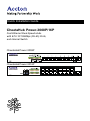
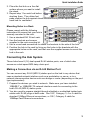
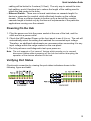
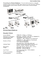
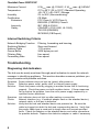
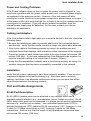
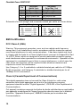
CheetaHub Power-3008P/3016P
Quick Installation Guide
Quick Installation Guide
CheetaHub Power-3008P/16P
Fast Ethernet Dual-Speed Hubs
with 8/16 10/100Mbps (RJ-45) Ports,
and Internal Switch
CheetaHub Power-3008P
CheetaHub Power-3016P
Copyright © 1999 by Accton Technology Corporation. All rights reserved.
No part of this document may be copied or reproduced in any form or by any means without the prior
written consent of Accton Technology Corporation.
Accton makes no warranties with respect to this documentation and disclaims any implied warranties
of merchantability, quality, or fitness for any particular purpose. The information in this document is
subject to change without notice. Accton reserves the right to make revisions to this publication
without obligation to notify any person or entity of any such changes.
International Headquarters
No. 1 Creation Road III,
Science-based Industrial Park
Hsinchu 300, Taiwan, R.O.C.
Phone: 886-3-5770-270
FAX: 886-3-5770-267
Internet: [email protected]
USA Headquarters
P.O. Box 51420
Irvine, CA 92619-1420
Phone Numbers Sales: 888-398-2101 or 949-707-4800
Support: 888-398-4101 or 949-707-4847
RMA:
888-398-3101 or 949-707-4828
FAX: 949-707-2460
Accton is a trademark of Accton Technology Corporation. Other trademarks or brand names
mentioned herein are trademarks or registered trademarks of their respective companies.
EH3008P
EH3016P
E0999-R02
150052-102
Contents
Introduction
1
Installing the Hub
1
Package Contents
Description of Hardware
Mounting the Hub
Stacking Hubs on a Flat Surface
Mounting Hubs in a Rack
Connecting the Hub System
Making a Connection via an RJ-45 Station Port
Making a Connection via an MDI Daisy-Chain Port
1
1
2
2
3
3
3
4
Powering On the Hub
5
Verifying Port Status
5
Verifying System Operation
6
Applications
6
Product Specifications
7
Repeater Criteria
Internal Switching Criteria
Troubleshooting
7
8
8
Diagnosing Hub Indicators
Power and Cooling Problems
Cabling and Adapters
Installation
8
9
9
9
Port and Cable Assignments
9
RJ-45 Port Description
EMI Certification
FCC Class A (USA)
Class A (Canada Department of Communications)
VCCI Class A Compliance (Japan)
BCIQ Class A Compliance (Taiwan)
CE Mark Declaration of Conformance (for EMI and Safety - Europe)
Safety Compliance
Underwriters Laboratories Inc. (USA)
Wichtige Sicherheitshinweise (Germany)
Warranty
9
10
10
10
11
11
11
11
11
12
13
i
ii
Quick Installation Guide
Introduction
The CheetaHub Power-3008P/16P provides 8 (16) RJ-45
ports that automatically adjust to the speed of the
attached device (for 10Mbps Ethernet or 100Mbps Fast
Ethernet connections). These dual-speed hubs contain
two internal repeater buses – one for 10Mbps traffic and
another for 100Mbps traffic. Traffic passing between
attached devices that operate at the same speed is confined
within the appropriate repeater bus. But when traffic must pass
between 10 and 100Mbps devices, when the destination address is not found in
the address table, or broadcast traffic is sent, data is forwarded to the other
repeater bus via an internal 10/100Mbps switch.
These hubs provide an ideal bridge between 10 and 100Mbps Ethernet networks.
Moreover, the smart design built into the display panel provides a friendly
interface that simplifies installation and network troubleshooting.
Installing the Hub
Before installing the hub, please verify that you have all the items listed under
“Package Contents.” If any of the items are missing or damaged, contact your
local Accton distributor. Also be sure you have all the necessary tools and
cabling before installing the hub. Note that this hub can be installed on any
suitably large flat surface or in a standard EIA 19-inch rack.
Package Contents
The CheetaHub Power-3008P/16P includes:
• CheetaHub Power-3008P (Model No. EH3008P)
Fast Ethernet dual-speed hub with 8 10/100Mbps ports, and internal switch
or CheetaHub Power-3016P (Model No. EH3016P)
Fast Ethernet dual-speed hub with 16 10/100Mbps ports, and internal switch
• Four rubber foot pads
• Quick Installation Guide
• Rack mount bracket kit
• Owner registration card
• AC power cord
Description of Hardware
These hubs provide 8 (16) dual-speed ports (10/100 Mbps). Each port
automatically senses the speed of the attached device, and channels data to the
appropriate repeater bus. The learning function of the hub stores the node
address and corresponding segment number (i.e., bus 1 or 2) of each incoming
packet in a routing table. If the source and destination node operate at different
speeds, this information is subsequently used to pass traffic to the segment
1
1
CheetaHub Power-3008P/3016P
containing the destination node via a 2-port switch that connects the two repeater
buses. By confining traffic to its respective collision domain, and only forwarding
traffic to the other segment when required, the overall load on the network is
significantly reduced.
These hubs provide a friendly design that simplifies installation and network
troubleshooting. The following figure shows the components of the EH3016P:
Mounting the Hub
These hubs can be placed directly on your desktop, or mounted in a rack.
Before you start installing the hub, make sure you can provide the right operating
environment, including power requirements, sufficient physical space, and
proximity to other network devices that are to be connected. Verify the following
installation requirements:
• Power requirements: 100 to 240 VAC (±10%) at 50 to 60 Hz (±3Hz). The hub's
power supply automatically adjusts to the input voltage level.
• The hub should be located in a cool dry place, with at least 10 cm. (4 in.) of
space at the front and back for access to the ports and ventilation.
• Place the hub out of direct sunlight, and away from heat sources or areas with
a high amount of electromagnetic interference.
• If you intend to mount the hub in a rack, make sure you have all the necessary
mounting screws, brackets, bolts and nuts, and the right tools.
• Check if network cables and connectors needed for installation are available.
Stacking Hubs on a Flat Surface
These CheetaHubs can be stacked any place where there is enough flat space,
such as on a table or desktop.
1. Stick the self-adhesive rubber foot pads (that come with this package) on
each of the 4 concave spaces located on the bottom of the first hub.
2
Quick Installation Guide
2. Place the first hub on a firm flat
surface where you want to install
the stack.
3. Repeat step 1 for each hub before
stacking them. The rubber foot
pads cushion the hub against shock/vibrations and provide space between
each hub for ventilation.
Mounting Hubs in a Rack
Please comply with the following
instructions to ensure that your hub is
securely mounted in the rack.
1. Use a standard EIA 19-inch rack.
2. Use the brackets and screws
supplied in the rack mounting kit.
3. Use a cross-head screwdriver to attach the brackets to the side of the hub.
4. Position the hub in the rack by lining up the holes in the brackets with the
appropriate holes on the rack, and then use the supplied screws to mount the
hub in the rack.
Connecting the Hub System
These hubs have 8 (16) dual-speed RJ-45 station ports, one of which also
serves as a dual-speed MDI daisy-chain port.
Making a Connection via an RJ-45 Station Port
You can connect any RJ-45 (MDI-X) station port on the hub to any device that
uses a standard network interface such as a workstation or server, or to a
network interconnection device such as a bridge or router (depending on the port
type implemented).
1. Prepare the devices you wish to network. Make sure you have installed
10BASE-T or 100BASE-TX network interface cards for connecting to the
hub's RJ-45 (MDI-X) station ports.
2. You also need to prepare straight-through shielded or unshielded twisted-pair
cables with RJ-45 plugs at both ends. Use 100Ω Category 3, 4 or 5 cable for
standard 10Mbps Ethernet connections, or 100Ω Category 5 cable for
100Mbps Fast Ethernet connections.
3
3
CheetaHub Power-3008P/3016P
3. Connect one end of the cable to the RJ-45 port of the network interface card,
and the other end to any available (MDI-X) station port on the hub. The RJ-45
ports support 10Mbps and 100Mbps Ethernet connections. When inserting an
RJ-45 plug, be sure the tab on the plug clicks into position to ensure that it is
properly seated. Using a hub in a stand-alone configuration, you can network
up to 8 (16) end nodes.
Do not plug a phone jack connector into any RJ-45 port.
This may damage the
hub. Use only twisted-pair cables with RJ-45 connectors that conform with FCC
standards.
Notes: 1. Make sure each twisted-pair cable does not exceed 100 meters (328 feet).
2. We advise using Category 5 cable for all network connections to avoid
any confusion or inconvenience in the future when you upgrade attached
devices to Fast Ethernet.
Making a Connection via an MDI Daisy-Chain Port
To make a direct connection to another compatible hub or switch:
1. Prepare straight-through shielded or unshielded twisted-pair cables with RJ-45
plugs at both ends. Use 100Ω Category 3, 4 or 5 cable for standard 10Mbps
Ethernet connections, or 100Ω Category 5 cable for 100Mbps Fast Ethernet
connections.
2. Plug one end of the network cable into Port 16MDI on the hub, and the other
end to any MDI-X station port on the other device. When inserting an RJ-45
plug, be sure the tab on the plug clicks into position to ensure that it is
properly seated.
Notes: 1. Make sure each twisted-pair cable does not exceed 100 meters (328
feet).
2. To connect to another hub or switch, you may also attach any RJ-45
MDI-X port on the hub to an MDI daisy-chain port on the other device. Or
attach crossover cabling to (MDI-X) station ports at both ends.
Restrictions on Cascade Length - When cascading to another repeater, note
that the attached repeaters will function as a single logical repeater, with all ports
attached to the same collision domain.
• 10 Mbps Cascade - Based on the IEEE 802.3 recommendation, you may
cascade up to four 10Mbps hubs.
• 100 Mbps Cascade - When cascading to a Fast Ethernet hub, limit the daisychain to two hubs. Another limitation for cascading Fast Ethernet concerns
connection length. All end-node devices (e.g., workstations or servers) must
be within 100 meters (328 feet) of the connected hub; and the overall length
between any two nodes should not exceed 205 meters (672 feet). The easiest
way to cascade two Fast Ethernet hubs is to connect the MDI daisy-chain port
on the front panel to an MDI-X port on the other hub. For example, if both
node A and B are linked to separate repeaters in a two hub system, each using
100 meters of cable to connect to their respective hub, then the inter-hub
4
Quick Installation Guide
cabling will be limited to 5 meters (16 feet). The only way to extend the interhub cabling, would therefore be to reduce the length of the cabling used to
attach the end nodes to the hubs.
• Ethernet Switch - There are no formal restrictions on cascade length if a
device is connected to a switch, which effectively breaks up the collision
domain. When a collision domain is broken up by a device like a switch,
cascade length is limited only by the time-out requirements of the particular
applications running over the network.
Powering On the Hub
1. Plug the power cord into the power socket at the rear of the hub, and the
other end into a power outlet.
2. Check the LED marked Power on the front panel to see if it is on. The unit will
automatically select the setting that matches the connected input voltage.
Therefore, no additional adjustments are necessary when connecting it to any
input voltage within the range marked on the rear panel.
3. The hub performs a self-diagnostic test upon power-on.
Note: The unit supports a "hot remove" feature which permits you to connect/
disconnect cables without powering off the hub and without disrupting the
operation of the devices attached to the hub.
Verifying Port Status
Check each connection by viewing the port status indicators shown in the
following figure and table.
EH3008P
5
EH3016P
5
CheetaHub Power-3008P/3016P
Port and Hub Status LEDs
LEDs
Condition
Status
Power
Green
Hub is receiving power.
Link
Yellow
Indicates a valid 10BASE-T connection between
port and attached device.
Green
Indicates a valid 100BASE-TX connection
between port and attached device.
Partition
Yellow
Port has been partitioned due to an abnormal
condition.
Col
Flashing
Yellow
Indicates that a packet collision has been
detected on the indicated segment.
Act
Flashing
Green
Indicates that the port is transmitting or receiving
data.
Util%
Green
Shows segment bandwidth utilization at 4/16/32%.
Yellow
Shows segment bandwidth utilization at 64%.
Verifying System Operation
Verify that all attached devices have a valid connection. The hub monitors the
link status for each port. If any device is properly connected to the hub and
transmitting a link beat signal, the Link indicator will light up for the
corresponding port. If the Link indicator fails to light, see Troubleshooting on
page 8.
Applications
These dual-speed CheetaHubs allow great flexibility in configuring your network.
You can use them to mix and match legacy Ethernet and Fast Ethernet network
resources on your local network. Moreover, you can easily extend your LAN by
making a high-speed connection to a collapsed backbone device (e.g., a switch
or a router).
Stand-Alone Network - These CheetaHubs have an internal switching function
that can be used in a simple stand-alone configuration as illustrated on the next
page. Regardless of whether you are making 10 or 100 Mbps connections with
twisted-pair cable, limit the distance for each cable to 100 meters (328 feet).
Cascading Hubs with the Daisy-Chain Port - You can easily connect to
another hub or switch via the RJ-45 MDI daisy-chain port on the front panel. The
figure on the next page shows a sample configuration. When connecting to
10Mbps Ethernet, the maximum number of hubs that can be cascaded is four
(with up to 100 meters or 328 feet of cable allowed between each hub). However,
when connecting to another Fast Ethernet hub, the number of hubs that can be
cascaded is limited to two, and the total network span allowed is only 205 meters
(672 feet).
6
Quick Installation Guide
Connecting to a Network Backbone - You can easily connect to a collapsed
backbone switch via the RJ-45 MDI daisy-chain port on the front panel. Because
a switch breaks up the collision domain, it can be used to connect multiple
CheetaHubs.
Product Specifications
Repeater Criteria
Access Method
Standards Conformance
Communication Rate
Media Supported
Number of Ports
Indicator Panel
Dimensions
Weight
Input Power
Power Consumption
Heat Dissipation
7
CSMA/CD, 10 Mbps or 100 Mbps
IEEE 802.3 10BASE-T, IEEE 802.3u 100BASE-TX
10/100 Mbps on all RJ-45 ports
10BASE-T - 100Ω Category 3,4,5 twisted-pair
100BASE-TX - 100Ω Category 5 twisted-pair
8 RJ-45 ports (EH3008P),
16 RJ-45 ports (EH3016P)
All models have 1 MDI daisy-chain port
LEDs for monitoring port speed, port link, port
partition, collision, utilization, and power
273 x 166 x 43 mm (10.75 x 6.54 x 1.69 in)
EH3008P: 1.38 kg (3.042 lbs)
EH3016P: 1.49 kg (3.285 lbs)
Full range power input: 100 to 240VAC,
50 to 60 Hz, 0.3A
20 Watts
68.2 BTU/hr
7
CheetaHub Power-3008P/3016P
Maximum Current
Temperature
Humidity
Certification
Emissions
Immunity
Safety
0.3A RMS max. @ 110VAC, 0.1ARMS max. @ 240VAC
0°C to 50°C (32 to 122°F) Standard Operating,
-40~70°C (-40~158°F) Storage
5% to 95% (Noncondensing)
CE Mark
FCC Class A, VCCI Class A,
EN55022 (CISPR22) Class A
IEC 1000-4-2/3/4/6
CSA/NRTL (C22.2.950, UL 1950),
TÜV/GS (EN60950)
IEC60950 (CB Report)
Internal Switching Criteria
Network Bridging Function
Switching Method
Address Table
Queue Buffer
Filtering Rate
Forwarding Rate
Filtering, forwarding and learning
Store-and-forward
1.7K entries
240K bytes per unit
Line speed
Line speed
Troubleshooting
Diagnosing Hub Indicators
The hub can be easily monitored through panel indicators to assist the network
manager in identifying problems. This section describes common problems you
may encounter and possible solutions.
Symptom: Power indicator does not light up (green) after power on.
Cause:
Defective power outlet, power cord, or internal power supply.
Solution: Check the power outlet by plugging in another device that is functioning
properly. Check the power cord with another device. If these measures
fail to resolve the problem, have the unit's power supply replaced by a
qualified Accton distributor.
Symptom: Link indicator does not light up after making a connection.
Cause:
Network interface (e.g., a network adapter card on the attached device),
network cable, or hub port is defective.
Solution: Verify that the hub and attached device are powered on. Be sure the
cable is plugged into both the hub and corresponding device. Verify that
the proper cable type is used and its length does not exceed specified
limits. Check the adapter on the attached device and cable connections
for possible defects. Replace the defective adapter or cable if necessary.
8
Quick Installation Guide
Power and Cooling Problems
If the Power indicator does not turn on when the power cord is plugged in, you
may have a problem with the power outlet, power cord, or internal power supply
as explained in the previous section. However, if the unit powers off after
running for a while, check for loose power connections, power losses or surges
at the power outlet, and verify that the fan on back of the unit is unobstructed and
running prior to shutdown. If you still cannot isolate the problem, then the
internal power supply may be defective. In this case, contact your Accton
distributor for assistance.
Cabling and Adapters
If the Link indicator fails to light when you connect a device to the hub, check the
following items:
•
Be sure the twisted-pair cable is properly attached to the connected device
and the hub. Verify that the media connector snaps into place when attached.
•
See if your cable is functioning properly by using it for another port and
attached device that displays valid indications when connected to the network.
•
Check the length of each twisted-pair cable to be sure it does not exceed 100
meters (328 feet). If you have cascaded two Fast Ethernet hubs together, be
sure the interhub cabling is no longer than 5 meters (16 feet).
•
Verify that the workstation's adapter card is functioning properly by trying it in
another computer that has been successfully connected to the network.
Installation
Verify that all system components have been properly installed. If one or more
components appear to be malfunctioning (e.g., the power cord or network
cabling), test them in an alternate environment where you are sure that all the
other components are functioning properly.
Port and Cable Assignments
RJ-45 Port Description
RJ-45 (MDI-X) station ports can be attached to any devices which use a
standard network interface (e.g., a workstation, server, bridge or router). RJ-45
(MDI) daisy-chain ports can be cascaded to a station port on similar networking
devices (e.g., another hub or switch). Use unshielded twisted-pair (UTP) or
shielded twisted-pair (STP) cable for RJ-45 connections: 100Ω Category 3, 4 or
5 cable for 10 Mbps connections or 100Ω Category 5 cable for 100 Mbps
connections. Also be sure that the length of any twisted-pair connection does
not exceed 100 meters (328 feet).
9
9
CheetaHub Power-3008P/3016P
Assignment
(Station Ports)
1
Inp ut Re ce ive Data +
2
Inp ut Re ce ive Data 3
Outp ut Transmit Data +
6
Outp ut Transmit Data 4,5,7,8 No t Use d
Pi n
Assignment
(Daisy-Chain Port)
Outp ut Transmit Data +
Outp ut Transmit Data Inp ut Re ce ive Data +
Inp ut Re ce ive Data No t Use d
Schematics for both straight and crossover twisted-pair cable are shown below.
Straight-Through
(Hub )
(Ad ap te r)
1 IRD+
1 OTD+
2 IRD2 OTD3 OTD+
3 IRD+
6 OTD6 IRD-
Crossover
(Hub )
1 IRD+
2 IRD3 OTD+
6 OTD-
(Hub )
1 IRD+
2 IRD3 OTD+
6 OTD-
EMI Certification
FCC Class A (USA)
Warning: This equipment generates, uses, and can radiate radio frequency
energy and, if not installed and used in accordance with the instruction manual,
may cause interference to radio communications. It has been tested and found
to comply with the limits for a Class A digital device pursuant to Subpart B of Part
15 of FCC Rules, which are designed to provide reasonable protection against
such interference when operated in a commercial environment. Operation of this
equipment in a residential area is likely to cause interference, in which case the
user, at his own expense, will be required to take whatever measures are
required to correct the interference.
Use Category 3, 4 or 5 unshielded or shielded twisted-pair cable for all 10Mbps
RJ-45 connection, and Category 5 unshielded or shielded twisted-pair for all
100Mbps RJ-45 connections.
Class A (Canada Department of Communications)
This digital apparatus does not exceed the Class A limits for radio noise
emissions from digital apparatus as set out in the interference-causing
equipment standard entitled "Digital Apparatus", ICES-003 of the Department of
Communications.
Cet appareil numérique respecte les limites de bruits radioélectriques applicables
aux appareils numériques de Classe A prescrites dans la norme sur le matériel
brouilleur: "Appareils Numérques", NMB-003 édictée par le ministère des
Communications.
10
Quick Installation Guide
VCCI Class A Compliance (Japan)
BCIQ Class A Compliance (Taiwan)
CE Mark Declaration of Conformance (for EMI and Safety - Europe)
This is to certify that this product complies with ISO/IEC Guide 22 and EN45014.
It conforms to the following specifications:
EMC: EN55022(1988)/CISPR-22(1985)
IEC1000-4-2(1995)
IEC1000-4-3(1995)
IEC1000-4-4(1995)
IEC 1000-4-6(1995)
Class A
4kV CD, 8kV AD
3V/m
1kV - (power line),
3Vrms
0.5kV - (signal line)
This product complies with the requirements of the Low Voltage Directive 73/23/
EEC and the EMC Directive 89/336/EEC.
Warning! Do not plug a phone jack connector in the RJ-45 port. This may
damage this device. Les raccordeurs ne sont pas utilisé pour le système
téléphonique!
Safety Compliance
Underwriters Laboratories Inc. (USA)
Important! Before making connections, make sure you have the correct Cord
Set. Check it (read the label on the cable) against the following specification list.
11
11
CheetaHub Power-3008P/3016P
Voltage
120 Vo lts
240 Vo lts
(No rth Ame rica)
240 Vo lts
(Euro p e o nly)
Cord Set Specifications
UL Liste d /CSA Ce rtifie d Co rd Se t
Minimum 18 AWG; typ e SVT o r SJT thre e co nd ucto r co rd
Maximum le ng th o f 15 fe e t
Paralle l b lad e , g ro und ing typ e attachme nt p lug rate d 15A, 125V
UL Liste d /CSA Ce rtifie d Co rd Se t
Minimum 18 AWG; typ e SVT o r SJT thre e co nd ucto r co rd
Maximum le ng th o f 15 fe e t
Tand e m b lad e , g ro und ing typ e attachme nt p lug rate d 15A, 125V
Co rd Se t with H05VV-F co rd having thre e co nd ucto rs with
minimum d iame te r o f 0.75 mm²
IEC-320 re ce p tacle ; male p lug rate d 10A, 250V
Wichtige Sicherheitshinweise (Germany)
1. Bitte lesen Sie diese Hinweise sorgfältig durch.
2. Heben Sie diese Anleitung für den späteren Gebrauch auf.
3. Vor jedem Reinigen ist das Gerät vom Stromnetz zu trennen. Verwenden Sie keine
Flüssigoder Aerosolreiniger. Am besten eignet sich ein angefeuchtetes Tuch zur
Reinigung.
4. Die Netzanschlu ßsteckdose soll nahe dem Gerät angebracht und leicht zugänglich sein.
5. Das Gerät ist vor Feuchtigkeit zu schützen.
6. Bei der Aufstellung des Gerätes ist auf sicheren Stand zu achten. Ein Kippen oder Fallen
könnte Beschädigungen hervorrufen.
7. Die Belüftungsöffnungen dienen der Luftzirkulation, die das Gerät vor Überhitzung schützt.
Sorgen Sie dafür, daß diese Öffnungen nicht abgedeckt werden.
8. Beachten Sie beim Anschluß an das Stromnetz die Anschlußwerte.
9. Verlegen Sie die Netzanschlußleitung so, daß niemand darüber fallen kann. Es sollte
auch nichts auf der Leitung abgestellt werden.
10. Alle Hinweise und Warnungen, die sich am Gerät befinden, sind zu beachten.
11. Wird das Gerät über einen längeren Zeitraum nicht benutzt, sollten Sie es vom Stromnetz
trennen. Somit wird im Falle einer Überspannung eine Beschädigung vermieden.
12. Durch die Lüftungsöffnungen dürfen niemals Gegenstände oder Flüssigkeiten in das
Gerät gelangen. Dies könnte einen Brand bzw. elektrischen Schlag auslösen.
13. Öffnen sie niemals das Gerät. Das Gerät darf aus Gründen der elektrischen Sicherheit
nur von authorisiertem Servicepersonal geöffnet werden.
14. Wenn folgende Situationen auftreten ist das Gerät vom Stromnetz zu trennen und von
einer qualifizierten Servicestelle zu überprüfen:
a. Netzkabel oder Netzstecker sind beschädigt.
b. Flüssigkeit ist in das Gerät eingedrungen.
c. Das Gerät war Feuchtigkeit ausgesetzt.
d. Wenn das Gerät nicht der Bedienungsanleitung entsprechend funktioniert oder Sie mit
Hilfe dieser Anleitung keine Verbesserung erzielen.
e. Das Gerät ist gefallen und/oder das Gehäuse ist beschädigt.
f. Wenn das Gerät deutliche Anzeichen eines Defektes aufweist.
Der arbeitsplatzbezogene Schalldruckpegel nach DIN 45 635 Teil 1000 beträgt 70dB(A) oder
weniger.
12
Quick Installation Guide
15. Zum Netzanschluß dieses Gerätes ist eine geprüfte Leitung zu verwenden. Für einen
Nennstrom bis 6A und einem Gerätegewicht größer 3kg ist eine Leitung nicht leichter als
H05VV-F, 3G, 0.75mm2 einzusetzen.
Warranty
Accton warrants to the original owner that the product delivered in this package
will be free from defects in material and workmanship for a period of three years
from the date of purchase from Accton or it’s Authorized reseller. For the
warranty to apply, you must register your purchase by returning the registration
card indicating the date of purchase and including proof of purchase. There will
be a minimal charge to replace consumable components, such as fuses, power
transformers, and mechanical cooling devices. The warranty does not cover the
product if it is damaged in the process of being installed. Accton recommends
that you have the company from whom you purchased this product install it.
THE ABOVE WARRANTY IS IN LIEU OF ANY OTHER WARRANTY, WHETHER
EXPRESS, IMPLIED OR STATUTORY, INCLUDING BUT NOT LIMITED TO ANY
WARRANTY OF MERCHANTABILITY, FITNESS FOR A PARTICULAR PURPOSE, OR
ANY WARRANTY ARISING OUT OF ANY PROPOSAL, SPECIFICATION OR SAMPLE.
ACCTON SHALL NOT BE LIABLE FOR INCIDENTAL OR CONSEQUENTIAL
DAMAGES. ACCTON NEITHER ASSUMES NOR AUTHORIZES ANY PERSON TO
ASSUME FOR IT ANY OTHER LIABILITY.
13
13
EH3008P
EH3016P
E0999-R02
150052-102