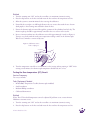
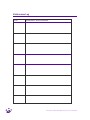
1
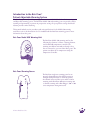
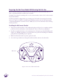
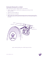
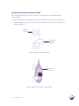
Bair Paws
Model 850
Warming Unit
Service
Manual
®
Warning: Electrical Shock Hazard. There are electrically live parts
within the warming unit when it is connected to a power source, even
when the hand-held temperature controller is in the OFF position.
Please forward to
Biomedical Engineering Department
Table of Contents
Introduction to the Bair Paws® Patient Adjustable Warming System.....................................1
Important Information about the Bair Paws Model 850 Warming Unit...............................2
Indications/Intended Use.........................................................................................2
Contraindication......................................................................................................2
Warnings.................................................................................................................2
Precautions...............................................................................................................3
Proper Use and Maintenance...................................................................................3
Read Before Servicing Unit......................................................................................3
Safety Inspection......................................................................................................3
Preparing the Bair Paws Model 850 Warming Unit for Use..................................................4
Installing the Wall-mount Bracket...........................................................................4
Mounting the Warming Unit to the Wall-mount ....................................................5
Mounting the Warming Unit on an IV Pole.............................................................6
Mounting the Warming Unit on a Bedrail...............................................................7
Mounting the Warming Unit with a Rail-mount to the Wall...................................8
Using the Temperature Controller Holder................................................................9
Service Procedures.............................................................................................................. 10
Calibrating the Operating Temperatures................................................................ 10
Testing the Over-Temperature (OT) Circuit........................................................... 11
Replacing the Filter................................................................................................ 12
Replacing the Temperature Controller and/or Hose................................................ 13
Replacing the Power Cord...................................................................................... 14
Reassembling the Warming Unit............................................................................ 15
Cleaning the Warming Unit................................................................................... 16
Technical Support and Customer Service........................................................................... 17
U. S. Customer Service........................................................................................... 17
When You Call for Technical Support.................................................................... 17
Repair and Exchange............................................................................................. 17
Bair Paws Warming Unit Limited Warranty...................................................................... 18
Specifications..................................................................................................................... 19
Maintenance Log............................................................................................................... 21
Definition of Symbols........................................................................................................23
Introduction to the Bair Paws®
Patient Adjustable Warming System
The Bair Paws patient adjustable warming system consists of the Model 850 forced-air warming unit
and disposable warming gowns. The Bair Paws Model 850 and warming gown can provide comfort
warming and prewarming to patients in preoperative settings. In postoperative settings the Model
850 can provide comfort warming.
This manual includes service procedures and unit specifications for the Model 850 warming
unit. Please refer to the Instructions for Use included with the Bair Paws warming gown for more
information about the gown.
Bair Paws Model 850 Warming Unit
®
The Bair Paws Model 850 warming unit has the
following key elements: a blower, a heating element,
and a hand-held temperature controller. The
warming unit delivers warmed air through a hose
that is connected to a port in a Bair Paws gown. The
patient can adjust the air temperature using the
temperature controller.
Bair Paws Warming Gowns
®
Arizant Healthcare Inc.
The Bair Paws single-use warming gown has an
integral, channeled insert that delivers warm air
through small perforations to warm the patient.
Air-channel inserts and hose ports enable comfort
warming with a Bair Paws 800 series warming unit
or clinical warming with a Bair Hugger® 500 or 700
series temperature management unit.
1
Important Information about the
Bair Paws Model 850 Warming Unit
Indications/Intended Use
The Model 850 warming unit is indicated for patient warming. This warming unit has been designed
for use with the Bair Paws warming gowns in all preoperative and postoperative settings.
Contraindication
Do not apply heat to lower extremities during aortic cross-clamping. Thermal injury may occur if
heat is applied to ischemic limbs.
Warnings
•
Do not warm patients with the warming unit’s hose alone. Thermal injury may result.
Always connect the hose to a Bair Paws warming gown before providing patient
warming.
• Do not use a forced-air warming device over transdermal medications; increased drug delivery,
patient death, or injury may occur.
• Use only Bair Paws warming gowns with the Model 850 warming unit. This warming unit has
been designed to operate safely with Bair Paws warming gowns; use with other products may
cause thermal injury. To the full extent permitted by law, the manufacturer and/or importer
declines all responsibility for thermal injury resulting from the unit being used in conjunction
with products other than Bair Paws warming gowns.
• The Model 850 warming unit is not intended for use in the operating room.
• Do not allow the warming unit’s hose to contact the patient’s skin during patient warming.
Thermal injury may result.
• Position the temperature controller cord and the hose away from the patient’s neck or shoulders
to avoid entanglement and/or injury.
• Equipment not suitable for use in the presence of a flammable anaesthetic mixture with air or
with oxygen or nitrous oxide.
2
Bair Paws® Model 850 Warming Unit Service Manual
Precautions
• Do not initiate patient warming unless the Model 850 warming unit is safely placed on a hard
surface or securely mounted. Otherwise, injury may result.
• The Model 850 warming unit meets the international electronic interference requirements of EN
60601-1-2 and EN 55011. However, if radio frequency interference with monitoring equipment
occurs, connect the warming unit to a different power source.
• Monitor the patient’s temperature and cutaneous response every 10-20 minutes or according to
institutional protocol and monitor the patient’s vital signs regularly.
Proper Use and Maintenance
Arizant Healthcare Inc. assumes no responsibility for the reliability, performance, or safety of the
unit if any of the following events occur:
• Modifications or repairs are performed by unqualified personnel.
• The warming unit is used in a manner other than that described in the Operator’s Manual or
Service Manual.
• The warming unit is installed in an environment that does not meet the appropriate electrical
and grounding requirements.
Read Before Servicing Unit
All repair, calibration, and servicing of the Model 850 warming unit must be performed by qualified,
medical equipment service technicians who are familiar with good practice for medical device repair.
If the warming unit does not require the manufacturer’s attention, Arizant Healthcare Inc. will ship
replacement parts to your location. Perform all repairs and maintenance in accordance with the
instructions provided with the replacement parts.
Safety Inspection
Perform a safety inspection after making repairs to the Model 850 unit and before returning the
unit to service. A safety inspection should include calibrating the operating temperature settings and
testing the over-temperature detection function as described in the Service Procedures section.
Arizant Healthcare Inc.
3
Preparing the Bair Paws Model 850 Warming Unit for Use
Before using the warming unit, make sure that it is safely placed on a flat, hard surface such as a
table, or securely mounted on a wall, IV pole, or bedrail.
Caution: Do not place the warming unit on a soft or uneven surface, such as a bed, or the air intake
may become blocked.
A wall-mount bracket is shipped with every warming unit; the brackets for mounting the warming
unit to an IV pole or a bedrail are available separately. Please contact your local sales representative
or call Arizant Healthcare® customer service at 1-800-733-7775 for more information about ordering
mounting brackets.
Installing the Wall-mount Bracket
1. Using the four wall-screw holes on the wall-mount bracket (see Figure 1) as a template, mark the
position for the four wall anchors on the desired wall. The use of a level is recommended.
2. Install four suitable wall anchors at the marked positions. If using the provided self-drilling wall
anchors, use a Phillips screwdriver to screw the anchors into position. If installing into industrialgrade plasterboard, predrilling may be required.
3. Hold the wall-mount bracket in position against the wall.
4. Screw the four provided screws through the wall-mount holes and into the wall anchors.
Wall screws
Setscrews
Figure 1. Front view of wall-mount bracket.
4
Bair Paws® Model 850 Warming Unit Service Manual
Mounting the Warming Unit to the Wall-mount
1. Slide the V-shaped bracket on the back of the warming unit into the groove of the
wall-mount bracket.
2. Tighten the 2 setscrews located on either side of the wall-mount bracket using a three-inch-long
(or longer) small Phillips screwdriver to lock the unit in place (see Figure 2).
Setscrew
Figure 2. Side view of warming unit in the wall-mount bracket.
Arizant Healthcare Inc.
5
Mounting the Warming Unit on an IV Pole
Caution: To prevent tipping, mount the Model 850 warming unit on an IV pole at a height that
ensures stability. We recommend mounting the warming unit no higher than 44 in. (112 cm) from
the floor on an IV pole with a minimum wheelbase radius of 14 in. (35.6 cm). Failure to do so may
result in IV pole tipping, leading to potential catheter site trauma and other patient injuries.
Note: The wall-mount bracket is shipped attached to the IV pole mount.
1. Position the IV pole-mount at the desired height on the IV pole.
2. Turn the clamp knob on the IV pole-mount clockwise to tighten the clamp to the pole
(Figure 3).
3. Slide the V-shaped bracket on the back of the warming unit into the groove
of the IV pole-mount.
4. Tighten setscrews as shown in Figure 2.
IV pole
IV pole-mount
Clamp knob
Figure 3. Installing a warming unit onto an IV pole.
6
Bair Paws® Model 850 Warming Unit Service Manual
Mounting the Warming Unit on a Bedrail
Note: The wall-mount bracket is shipped attached to the rail-mount.
1. Slide the V-shaped bracket on the back of the warming unit into the groove of the
rail-mount bracket.
2. Tighten the setscrews (see Figure 2).
3. Hang the rail-mount on the bedrail.
4. Wrap the safety strap around the bedrail and connect the end to the fastener on the strap. The
safety strap will prevent the warming unit from falling if the unit is accidentally dislodged from
the bedrail.
Bedrail
Rail-mount
Safety strap
Figure 4. Mounting warming unit on a bedrail using the rail-mount.
Arizant Healthcare Inc.
7
Mounting the Warming Unit with a Rail-mount to the Wall
1. Using the wall-screw holes on the rail-to-wall bracket (see Figure 5) as a template, mark the
position for the two wall anchors on the desired wall. The use of a level is recommended.
2. Install two suitable wall anchors at the marked positions. If using the provided self-drilling wall
anchors, use a Phillips screwdriver to screw the anchors into position. If installing into industrialgrade plasterboard, predrilling may be required.
3. Hold the rail-to-wall bracket in position against the wall.
4. Screw the two provided screws through the bracket holes and into the wall anchors.
5. Hook the warming unit with the attached rail-mount to the rail-to-wall bracket as depicted in
Figure 5.
Precaution: For use only with the Model 850 warming unit.
Note: A minimum of two wall anchors must be used to secure the rail-to-wall bracket to the wall.
Additional wall anchors (up to a total of four) can be used for extra support.
Rail-to-wall
bracket
Figure 5. Placing the warming unit with a rail-mount onto the rail-to-wall bracket.
8
Bair Paws® Model 850 Warming Unit Service Manual
Using the Temperature Controller Holder
The controller holder helps to prevent cord clutter around the patient or accidental damage
to the controller.
1. Press the holder onto the warming unit hose so it is within the patient’s reach (see Figure 6).
2. Slide the temperature controller into the holder. It should fit securely with the dial facing the
patient (see Figure 7).
Warming
unit hose
Temperature
Controller
holder
Figure 6. Temperature Controller holder.
Temperature
Controller
Figure 7. Temperature Controller seated in holder.
Arizant Healthcare Inc.
9
Service Procedures
Calibrating the Operating Temperatures
Service Frequency
• Calibrate the unit before placing it in service if the ambient temperature where the warming unit
will be used is higher than 24°C (75°F).
• Always recalibrate after performing service procedures.
• Routinely calibrate every 6 months.
Tools/Equipment Needed
• Model 90055 Temperature Test Kit (thermocouple included)
• 2 mm screwdriver
• Medium Phillips screwdriver
• Calibrated thermometer
Warnings:
• The Model 850 hand-held temperature controller must be at its maximum (warmest) setting
when calibrating; otherwise, temperature settings may be inaccurate and patient injury could
result.
• Do not calibrate the Model 850 warming unit above 40°C; patient injury may result.
Precaution:
• Perform all calibrations of the Model 850 warming unit using an Arizant Healthcare Model
90055 Temperature Test Kit.
• Perform calibration testing at an ambient temperature similar to the area where the Model 850
warming unit will be used.
Notes:
The Model 90055 Temperature Test Kit simulates the operating characteristics of Bair Paws gown
when used with the Bair Paws Patient Adjustable Warming System.
When using the Model 90055 Test Kit, take temperature readings using a calibrated thermometer
that can accept a male, subminiature connector and read a “K” type thermocouple (e.g., a Fluke
Model 52 K/J Thermometer). If the test unit’s connector does not fit your thermometer, remove
the connector from the test unit and attach a connector that fits your meter. Be certain to observe
polarity.
Arizant Healthcare Inc. assumes no responsibility for the reliability, safety, or performance of the
Model 850 warming unit if calibration tests or adjustments are made in any manner other than
those described here. Improper measurement or adjustment of the normal operating temperature for
the Model 850 unit could result in patient exposure to temperatures outside of the indicated range
and may lead to patient injury.
10
Bair Paws® Model 850 Warming Unit Service Manual
Method
1. Turn the warming unit “ON” and set the controller to its maximum (warmest) setting.
2. Press the clip buttons on the hose end and insert the hose end into the temperature test kit.
3. Allow the system to warm 10 minutes before starting the calibration.
4. Extend the hose straight to its full length. Remove the two screws that attach the case bottom
(dark purple) to the warming unit and slide it down the hose.
5. Ensure the thermocouple is inserted through the grommet of the cylindrical test kit body. The
thermocouple tip should be approximately centered in the cross section of the test kit.
6. Insert a 2 mm screwdriver into the calibration access hole approximately 1/2 inch (see Figure 8).
Turn pot very slowly until the steady state temperature reading is 40°C on the thermocouple.
Wait at least 5 minutes to ensure steady state.
Figure 8. Calibration access
hole to adjust pot.
6. Turn the temperature controller to its minimum (coolest) setting without turning it “OFF.” After
waiting several minutes, the thermocouple temperature should read 32°C or less.
Testing the Over-temperature (OT) Circuit
Service Frequency
Test every 6 months.
Tools/Equipment Needed
• Model 90055 Temperature Test Kit (thermocouple included)
• Small screwdriver
• Medium Phillips screwdriver
• Calibrated thermometer
Method
Note: The OT threshold temperature cannot be adjusted. If problems occur, contact Arizant
Healthcare customer service.
1. Turn the warming unit “ON” and set the controller to its maximum (warmest) setting.
2. Press the clip buttons on the hose end and insert the hose end into the temperature test kit.
Arizant Healthcare Inc.
11
3. Extend the hose straight to its full length. Remove the two screws that attach the case bottom
(dark purple) to the warming unit and slide it down the hose.
4. Allow the system to warm 10 minutes before starting the test.
5. With a small screwdriver, press the OT test button (see Figure 9). Continuously depress for the
duration of the over-temperature test.* When functioning properly, the “Over-Temp” indicator
will illuminate, the OT value will be below 53°C, and the unit will switch off within 2 minutes.
If this does not occur, return the unit to Arizant Healthcare Inc. for service.
Figure 9. OT test button hole.
6. Reposition the case bottom with the filter and attach to the warming unit with two screws.
Replacing the Filter
Service Frequency
Inspect the warming unit filter every 3 months and replace at least every 6 months.
Tools/Equipment Needed
• Medium Phillips screwdriver
• Replacement filters (available from Arizant Healthcare Customer Service)
Method
1. Disconnect the warming unit from the power source.
2. Remove the two screws that attach the case bottom (dark purple) to the warming unit.
3. Slide the case bottom down the hose, remove the used filter, and replace with a new filter.
4. Reposition the case bottom (with the new filter) and attach to the warming unit with the two
screws.
5. Reconnect the warming unit to the power source and turn the temperature controller “ON” to
make sure the warming unit functions properly before returning to service.
* Pressing the OT test button places the heater in a full-on, unregulated condition; therefore, the unit may
become slightly warm to the touch.
12
Bair Paws® Model 850 Warming Unit Service Manual
Replacing the Temperature Controller and/or Hose
Tools/Equipment Needed
• Medium Phillips screwdriver
• Needle-nose pliers
Method
1. Disconnect the warming unit from the power source.
2. Remove the two screws that attach the case bottom (dark purple) to the warming unit.
3. Slide the case bottom down the hose to expose the hose connection point.
4. Remove the two screws that fasten the hose to the warming unit: 1 on front and 1 on the back of
the warming unit.
5. Pull the hose out of the warming unit to expose the wire connector.
6. Unplug the wire connector so the hose assembly is separated from the unit (see Figure 10).
Figure 10. Wire connector.
7. Remove the two screws on the collar at the wire junction on the hose, and pull the wire out
through the hose hole (see Figure 11).
Arizant Healthcare Inc.
Figure 11. Warming unit hose wire junction.
13
8. Using either a replacement temperature controller assembly or a replacement hose, thread the
controller wire through the hose hole. Hold the hose vertical and let the wire connector drop
through to the hose end that attaches to the warming unit.
9. Reattach the hose to the warming unit by following steps 2 – 7 in reverse order.
10. Recalibrate the temperature and test the over-temperature circuit before returning the unit to
service.
Replacing the Power Cord
Tools/Equipment Needed
• Medium Phillips screwdriver
• 1/32” flat screwdriver
• ESD strap
• Model 850 replacement power cord
Method
1. Disconnect the warming unit from the power source and put on an ESD strap before starting
the procedure.
2. Remove the two screws that attach the case bottom (dark purple) to the warming unit and slide
the case bottom down the hose.
3. Remove the four screws on the back side of the unit enclosure.
4. Remove the one remaining screw on the front side of the enclosure that holds the hose to the
warming unit. Lift off the front enclosure.
5. Disconnect the hose and the temperature controller wire connector (see Figure 10).
6. Disconnect the six-pin power connector by depressing and pulling on the snap tab.
7. Remove the five screws on the printed circuit board (PCB), and set the PCB aside.
8. Disconnect the black wire and the white wire by inserting a 1/32” screwdriver into the
corresponding slots in the power connector (see Figure 12).
Figure 12. Power connector.
9. Remove 4 screws on the motor assembly and lift away from the warming unit enclosure. Pull out
the old power cord.
14
Bair Paws® Model 850 Warming Unit Service Manual
10. Route the new power cord through the enclosure hole and around the case as shown. Make sure
the cord is held firmly by the notches in the case. Thread the crimped black and white wires
through the case opening as shown in Figure 13.
Figure 13. Power cord configuration in the warming unit case.
Reassembling the Warming Unit
11. Replace the motor assembly in the case and screw into place (see step 9). Make sure the motor
wires are not pinched between the motor and the case.
12. Plug the black wire into slot 1 and the white wire into slot 3 in the power connector (see step 8).
13. Replace the PCB over the motor assembly and screw into place (see step 7). Make sure that the
heaters are not damaged and the wires are not pinched between the case and the PCB.
14. Plug the power connector into the PCB (see step 6).
15. Seat the temperature controller wire connector into the PCB (see step 5).
16. Connect the hose to the unit, making sure the wire is not pinched between the hose end and the
PCB.
17. Replace the front enclosure. On the back side, screw the enclosures together in 4 places (see step
3). Turn the unit over and fasten the screw over the hose (see step 4).
18. Replace the case bottom over the case. Make sure the filter stays in place. Screw the case bottom
with filter into the case in 2 places (see step 2).
19. Recalibrate the temperature and test the over-temperature circuit before returning the unit to
service.
Arizant Healthcare Inc.
15
Cleaning the Warming Unit
Service Frequency
As needed.
Tools/Equipment Needed
• Soft cloth
• Mild cleaning solution or antimicrobial spray*
• Dry soft cloth
Warning: Do not immerse any part of the warming unit while cleaning it. Moisture will damage
the components, and thermal injury may result.
Precautions:
• Do not use a dripping wet cloth to clean the warming unit. Moisture may seep into the electrical
contacts and damage the components.
• Do not use harsh solvents to clean the warming unit.* Solvents may damage the labels and other
plastic parts.
Method
1. Disconnect the warming unit from the power source before cleaning.
2. Wipe the cabinet, the temperature controller, and the outside of the hose with a damp, soft cloth
and a mild cleaning solution or antimicrobial spray.
3. Dry with a separate soft cloth.
* WINDEX® multi-use liquid cleaner, ENVIROCIDE® disinfectant, and ALCONOX® industrial
cleaner are three products that can be used to clean the equipment, as well as 3% household bleach,
isopropanol, ethanol, ammonia or other phosphate-based glass cleaning solutions.
WINDEX is a registered trademark of S.C. Johnson & Son, Inc.
ENVIROCIDE is a registered trademark of Metrex Research Corporation
ALCONOX is a registered trademark of Alconox, inc.
16
Bair Paws® Model 850 Warming Unit Service Manual
Technical Support and Customer Service
U.S. Customer Service
TEL:
800-733-7775
952-947-1200
FAX:
800-775-0002
952-947-1400
When You Call for Technical Support
Please be ready to give the Technical Support Representative the serial number of your Bair Paws
warming unit. The serial number is located on the back of the unit.
Repair and Exchange
Call Arizant Healthcare customer service if your Model 850 warming unit requires service. A
customer service representative will give you a Return Authorization (RA) number. Please use
this RA number on all correspondence concerning your warming unit. Your customer service
representative will also send a shipping carton to you at no charge upon request.
Arizant Healthcare Inc.
17
Bair Paws Warming Unit Limited Warranty
Two-Year Limited Warrantya, c
Arizant Healthcare Inc. (“Company”) warrants to the original end-user (“User”)a that each Bair Paws
warming unit (“Unit”)b will be free from defects in materials and workmanship under normal use and
service for two yearsc from the date of shipment. THIS LIMITED WARRANTY IS IN LIEU OF ALL
OTHER WARRANTIES, INCLUDING ANY IMPLIED WARRANTIES APPLICABLE TO THE
UNITS, SUCH AS WARRANTIES OF MERCHANTABILITY AND FITNESS FOR A PARTICULAR
PURPOSE, WHICH ARE HEREBY DISCLAIMED AND EXCLUDED BY THE COMPANY. Some
jurisdictions may not allow the disclaimer of implied warranties, so the above limitations
may not apply to you.
Limitation of Remedies
If, during the limited warranty period, a Unit or part is found to be defective because of defects in materials
and workmanship under normal use and service, it will be repaired or replaced without charge. Defective
Units or parts must be returned to Arizant Healthcare Inc., 10393 West 70th Street, Eden Prairie, MN 55344.
Repair or replacement of a Unit or part under the terms of this limited warranty in no way lengthens the
limited warranty period.
User’s exclusive remedy, IN LIEU OF ALL INCIDENTAL, SPECIAL OR CONSEQUENTIAL
DAMAGES OF ANY KIND, INCLUDING FOR NEGLIGENCE, is limited to repair or replacement of a
defective Unit or part under the terms and conditions of this limited warranty. Company will bear no other
expenses. Some jurisdictions do not allow the exclusion or limitation of incidental or consequential damages,
so this limitation may not apply to you.
This limited warranty does not apply to certain of the parts listed below or to any Unit in which parts other
than replacement parts made or approved by the Company have been used if such parts are the cause of
failure. Company shall have no obligation under this limited warranty to make repairs or replacements
necessitated in whole or in part by accidents, fault, or negligence of User.
PART
Filters
Fuses
Hose
Cords
Labels
Temperature controller
Mounting brackets
WARRANTY PERIOD (from the date of shipment to User)
N/A
N/A
1 year
1 year
1 year
1 year
1 year
This limited warranty applies only to User and is valid only for the use of Units with Bair Paws
gowns. The use of any gowns or other products not manufactured or approved by Company for
use with Units invalidates this limited warranty. Use of Units in a manner not specified in the
instructions for use invalidates this limited warranty. This limited warranty is non-transferable.
This limited warranty gives you specific legal rights, and you may also have other rights which vary from
jurisdiction to jurisdiction.
a. Distributors are not end-users unless they have purchased a unit for their sales representatives’ use.
b. This limited warranty is valid only for Bair Paws warming units. It does not
apply to Bair Paws gowns or accessories or any other product.
c. Refurbished Units have a one-year limited warranty from the date of shipment to
User. As indicated below, this limited warranty does not apply to certain parts and
other parts have a one-year limited warranty from the date of shipment to User.
18
Bair Paws® Model 850 Warming Unit Service Manual
Specifications
Physical Characteristics
dimensions of warming unit
11 in. high x 2.5 in. deep x 7.7 in. wide
27.9 cm high x 6.4 cm deep x 19.6 cm wide
dimensions of temperature controller
2.5 in. wide x 5.8 in. long
6.4 cm wide x 14.7 cm long
weight of warming unit
6.3 lb; 2.9 kg.
mounting optionsWall mount bracket, IV pole clamp, and rail-mount
bracket with safety strap.
hoseDetachable, flexible, and washable. 78 in. long x 1.5 in.
wide; 198 cm long x 3.8 cm wide
filtration system
Dust filter included.
recommended filter change
Change at least every 6 mo.
Temperature Characteristics
temperature control
Electronically controlled using integrated circuit
sensor.
heat generated
750 BTU/hr (average)
average operating temperatures
at the end of the hose
Variable: ambient to 40˚ ± 3˚C
ambient to 104˚ ± 5.4˚F
Safety System Characteristics
thermostat
Independent electronic and heater (electromechanical)
overcurrent protection
Fused input line.
safety featureOver-temperature:
color indicator light illuminates,
heater and blower shut down.
certificationsIEC
60601-1: UL 60601-1; CAN/CSA-C22.2, No.
601.1; EN 60601-1-2; EN 55011; ASTM F2196-02
classificationsClassified
under EN 60601-1 Guidelines (and other
national versions of the Guidelines) as Class II, Type
BF, Ordinary equipment, Continuous operation. Not
suitable for use in the presence of flammable anesthetic
mixtures with air or with oxygen or nitrous oxide.
Classified by Underwriters Laboratories Inc. with
respect to electric shock, fire, and mechanical hazards
only, in accordance with UL 60601-1, ASTM F219602, and Canadian/CSA C22.2, No. 601.1. Classified
under the Medical Device Directive (93/42/EEC) as a
Class IIa device.
Arizant Healthcare Inc.
19
Specifications - Continued
Electrical Characteristics
20
blower motor
Airflow: 7-9 cfm
power consumption
Peak: 290W leakage current
Meets IEC 60601-1 and UL 60601-1 requirements
heating element
285W Resistive
power cord
15-foot, SJT, 3 cond., 10A
device ratings
110-120 VAC, 60 Hz, 3.0 A
fuses 3.0 A
temperature controller cord
32” from hose collar, 4 cond., Max. voltage: 5V
Average: 150W Bair Paws® Model 850 Warming Unit Service Manual
Maintenance Log
Date
Maintenance Action Performed
Arizant Healthcare Inc.
21
Maintenance Log
Date
22
Maintenance Action Performed
Bair Paws® Model 850 Warming Unit Service Manual
Definition of Symbols
The following symbols may appear on the product, on the exterior packaging, or in
the product labeling.
ON/STANDBY
Temperature control
Equipotentiality plug (ground)
Fuse
Attention, consult accompanying documents
Dangerous voltage
Type BF Equipment (patient applied)
Voltage, alternating current (AC)
Protective earth ground
Ground
Class II Equipment
No free hosing
Arizant Healthcare Inc.
23
Arizant Healthcare Inc.,
10393 West 70th Street,
Eden Prairie, MN 55344 USA
TEL 800-733-7775 • 952-947-1200
FAX 800-775-0002 • 952-947-1400
www.bairpaws.com
Bair Hugger, Bair Paws, Arizant, Arizant Healthcare, bright ideas that work,
and the Bair Paws and Arizant logos are trademarks of Arizant Healthcare Inc.,
registered or pending in the U.S. Patent & Trademark Office and in other countries.
U.S. Patent 7,226,454; 6,876,884; D485,338. Other patents pending.
©2008 Arizant Healthcare Inc. All rights reserved.
201029F 05/08