1
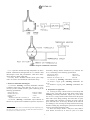
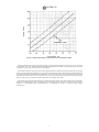
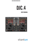
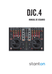
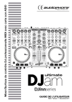
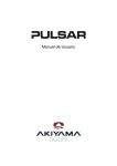
An American National Standard
Designation: D 1740 – 01
Standard Test Method for
Luminometer Numbers of Aviation Turbine Fuels1
This standard is issued under the fixed designation D 1740; the number immediately following the designation indicates the year of
original adoption or, in the case of revision, the year of last revision. A number in parentheses indicates the year of last reapproval. A
superscript epsilon (e) indicates an editorial change since the last revision or reapproval.
This test method has been adopted for use by government agencies to replace Method 2108 of Federal Test Method Standard No. 791b.
1. Scope
1.1 This test method2 covers the measurement of the flame
radiation characteristics of aviation turbine fuels and other
similar distillate fuels expressed in terms of luminometer
numbers. There is good correlation between smoke point (Test
Method D 1322) and luminometer number which is presented
in Appendix X1.2
1.2 This standard does not purport to address all of the
safety concerns, if any, associated with its use. It is the
responsibility of the user of this standard to establish appropriate safety and health practices and determine the applicability of regulatory limitations prior to use. For specific
precautionary statements, see 7.1, 7.2, 8.1, 8.2 and Annex A1.1.
4. Summary of Test Method
4.1 The luminometer number of a fuel is determined by
burning the fuel in the ASTM-CRC Luminometer lamp and
obtaining a curve of flame radiation, as measured by an optical
filter and photo cell unit against the temperature rise across the
burner measured by a thermocouple placed just above the
flame. This temperature rise is compared with that obtained on
a pair of reference fuels at a constant radiation level. To ensure
that the constant rating level is the same in all units, it is
defined as the smoke point of tetralin. Luminometer number is
calculated from the difference in temperature rise between the
test fuel and the temperature rise for tetralin divided by the
difference in temperature rise for isooctane and tetralin.
NOTE 1—It is the intent of Subcommittee J to ballot to withdraw this
test method when due for reapproval in 2006, because of very limited and
declining use to determine compliance with aviation turbine fuel specifications.
5. Significance and Use
5.1 This test method provides an indication of the relative
radiation emitted by the combustion products of gas turbine
fuels from a diffusion flame. The radiation level, expressed as
luminometer number, is related to the hydrocarbon type composition of such fuels. A high luminometer number indicates a
fuel of low radiation characteristics.
5.2 The luminometer number (and the smoke point with
which it can be correlated) is qualitatively related to the
potential radiant heat transfer from the combustion products of
the fuel. Because radiant heat transfer exerts a strong influence
on the metal temperature of combustor liners and other hot
section parts of gas turbines, the luminometer number provides
a basis for correlation of fuel characteristics with the life of
these components.
2. Referenced Documents
2.1 ASTM Standards:
D 1322 Test Method for Smoke Point of Aviation Turbine
Fuels3
D 1655 Specification for Aviation Turbine Fuels3
D 2880 Specification for Gas Turbine Fuel Oils3
3. Terminology
3.1 Definitions of Terms Specific to This Standard:
3.1.1 luminometer number—a measure of flame temperature at a fixed flame radiation in the green-yellow band of the
visible spectrum.
3.1.1.1 Discussion—It can be correlated with combustion
characteristics of fuels for use in current commercial aviation
turbine engines.
6. Apparatus
6.1 ASTM-CRC Luminometer,4 shown schematically in
Fig. 1, consisting of three main parts:
6.1.1 A small wick-type lamp in which the sample is
burned,
6.1.2 An optical filter and photocell circuit which indicates
the intensity of flame radiation in the range from 4800 to 7000
˚ and
A
1
This test method is under the jurisdiction of ASTM Committee D02 on
Petroleum Products and Lubricants and is the direct responsibility of Subcommittee
D02.J0 on Aviation Fuels.
Current edition approved June 10, 2001. Published July 2001. Originally
published as D 1740 – 60 T. Last previous edition D 1740 – 96.
2
This test method was developed on the basis of cooperative work carried out by
the Coordinating Research Council and published in CRC Report “Evaluation of
CRC Luminometer” (CRC Project No. CA-16-58). June 1959.
3
Annual Book of ASTM Standards, Vol 05.01.
4
The ASTM-CRC Luminometer, made by ERDCO Engineering Corp., 721
Custer Ave., P. O. Box 1310, Evanston, IL 60204 has been used to develop the
precision of Test Method D 1740.
Copyright © ASTM International, 100 Barr Harbor Drive, PO Box C700, West Conshohocken, PA 19428-2959, United States.
1
D 1740 – 01
FIG. 1 Diagram of ASTM-CRC Luminometer
and kidney damage and the formation of eye cataracts. See
A1.2.) conforming to the following specifications:
6.1.3 A system to measure the lamp temperature rise above
ambient. Luminometers through serial No. 377 include a dual
thermocouple circuit and potentiometer, while later instruments include a digital output unit.
6.2 Lamp Wicks—Standard ASTM smoke point lamp
wicks5 are used in the ASTM-CRC luminometer lamp.
Specific gravity 25/25 C
Refractive index, Nd20 C
Distillation, from first drop to dry, °C
7.3 Acetone, cp. (Warning—Flammable. See A1.3.)
7.4 Toluene, reagent grade, (Warning—Flammable. See
A1.4.)
7.5 Methanol, reagent grade, (Warning—Flammable. See
A1.5.)
7. Reference Materials and Reagent
7.1 Isooctane (Warning—Extremely flammable. Harmful
if inhaled. Vapors may cause flash fire. See A1.1.) (2,2,4trimethyl pentane) ASTM reference grade conforming to the
following specifications:
Density at 20C, g/mL
Refractive index, Nd20 C
Freezing point, °C
Distillation:
Temperature at which 50 % is recovered, °C
0.969 to 0.97
1.5396 to 1.5410
206 to 208
8. Preparation of Apparatus
8.1 Cleaning the Lamp—Before each test, clean the top and
inside of the wick guide (in the lamp body) with acetone
(Warning—Extremely flammable. Vapors may cause flash
fire. See A1.3.) using a small test tube brush. Protect the optical
filter with a tissue during cleaning. Check the filter for spots
after cleaning and if the filter is found to be spotty, clean in
place with lens tissue. If necessary, the filter can be removed
for cleaning by first removing the lamp and then unscrewing
the filter retaining ring. Following the replacement of the lamp,
reference fuel checks should be made.
8.2 Wicks and Sample Holders—Only new wicks shall be
used. Extract all wicks for at least 25 cycles in a reflux
0.69175 to 0.69205
1.39135 to 1.39165
−107.52
99.20 to 99.30
7.2 Tetralin, (Warning—Combustible. Vapor harmful. In
animal tests, repeated oral or inhalation exposures caused liver
5
Standard smoke point wicks are obtainable through Erdco Engineering Corp.,
721 Custer Ave., PO Box 1310, Evanston, IL 60204 and Koehler Instrument Co.,
1579 Sycamore Ave., Bohemia, NY 11716.
2
D 1740 – 01
eter pointer rests at “0” (mechanical zero). Turn the lower left
switch to STD and hold while adjusting the battery knob (upper
left) until the galvanometer rests at“ 0” (electrical zero). If the
meter will not standardize, replace the internal potentiometer
battery.7
8.4.2 Temperature Indicator (Serial No. 378 and
higher)—Be sure the ambient air thermocouple is in its
operating position (pulled to the right toward the lamp) and the
stack thermocouple is connected. The output switch must be in
the “OFF” position. Place the power switch in the “F”ahrenheit
position. No additional adjustment is required. Return power
switch to the “OFF” position between tests to conserve
batteries. (Note 6.)
8.4.2.1 Four type 1.2 AHR SC Size rechargeable batteries
are used to supply power for the unit. To recharge the battery
pack, insert the battery charger plug into the “RECHARGE”
jack located on the front panel. Use the 115 volt charger only
on a 115 volt line (Note 6).
condenser with an equal volume mixture of toluene
(Warning—Flammable. Vapor harmful. See A1.4.) and anhydrous methanol (Note 2). (Warning—Flammable. Vapor
harmful. May be fatal or cause blindness if swallowed or
inhaled. Cannot be made nonpoisonous. See A1.5.) Allow the
wicks to dry partially for 5 min, then place them in an oven and
dry for 1⁄2 h at 100 to 110°C. Store in a dessicator until used.
Thoroughly wash the sample holder in acetone and dry (Note
3). Then insert a dry wick in the wick tube of the clean sample
holder. A piece of thin wire hooked through the end of the wick
will allow the wick to be pulled through the tube without
twisting. Use a clean razor blade or other sharp instrument to
cut off the wick flush with the top of the wick tube (Note 4).
Raise the wick by twisting the lower part until the end of the
wick protrudes. Then, pull the wick up and remove any twists
in the wick by rotating the ends of the wick. Also pull the wick
down until the top of the wick is 1⁄4 in. (6.4 mm) above the
tube. Trim any frayed ends from the top of the wick. If the wick
has not been cut square, recut and position as outlined above.
(Note 5.)
NOTE 6—For maximum battery life, it is recommended that the unit7 be
charged only when the discharged battery indication (display indicates
HELP) is observed. Do not charge for periods longer than 18 h. Charge
unit before initial use.
NOTE 2—If extraction facilities are not available, request supplier to
supply wicks that have been extracted.
NOTE 3—If either fuel or acetone vapors are not removed from the
sample holder during the cleaning and drying operations, erroneous
ratings can be obtained.
NOTE 4—Some razor blades have a protective chemical coating which
should be removed with a solvent.
NOTE 5—An alternative method of preparing a wick free of twists and
frayed ends utilizes a Wick Trimmer Assembly.6 The wick trimmer holder
is inserted over the top of the wick tube and the long-nosed triceps are
inserted through the tube and holder. The wick is grasped and carefully
pulled through the tube without twisting. A new clean sharp razor is used
to cut the wick at the face of the holder and remove wisps and frayed ends.
When the holder is removed, the wick will be at the correct height in the
tube. The tube is then inserted into the candle and screwed home. The
candle is inserted into the lamp.
Display Symbols
HI—
Help—
F—
8.4.3 Digital Temperature Indicator (Serial No. 410 and
Higher)—Be sure the ambient air thermocouple is in its
operating position (fully extended to the lamp) and the stack
thermocouple is connected. Turn unit on by pressing the
On/Off position on front key pad. Input temperature will be
displayed.
8.4.3.1 Battery is a standard 9 V to supply power for the
unit.
8.5 Luminometer Meter8—Turn the switch located below
the right hand side of the luminometer meter to the OFF
position. Adjust the meter to “0” by rotating the meter arm
pivot screw on the lower front center of the meter. Then turn
the switch to ZERO and turn the zeroing adjustment control
located below the left-hand side of the meter until the meter
arm rests at “0”. To facilitate zeroing use the coarse and a fine
zero adjustment. Next turn the switch to A1, A2, B1, and B2 to
check the battery voltage. If on each switch position the meter
rests above the appropriate mark on the meter scale, the
batteries are satisfactory and the unit is ready for use. If the
batteries are under strength, replace them. When replacing the
“B” batteries also replace the photocell batteries located inside
the photocell box.
8.3 The flame axis of the ASTM-CRC Luminometer lamp
must be vertical for proper operation. Adjustable cabinet
vibration mounts are provided for this purpose. Adjustment can
be checked by a small level positioned on the large flame
height adjusting ring. The level of the lamp should be checked
in both the front to rear plane and the side to side plane. If at
any time the position of the cabinet or the lamp is disturbed, the
lamp level must be checked. If the position of the stack
thermocouple is disturbed or the thermocouple replaced, the
thermocouple should be positioned with the junction exactly on
the lamp centerline. The bottom of the thermocouple shield
should be exactly 1 in. (25.4 mm) above the wick guide.
Suitable gages for this purpose are available from the manufacturer.
8.4 Temperature Measurement:
8.4.1 Potentiometer (Serial No. 377 and earlier)—Be sure
the ambient air thermocouple is in its operating position (pulled
to the right toward the lamp) and the stack thermocouple is
connected. Turn the right switch of the potentiometer to TEST
position; also turn the lower left switch to ZERO position and
hold while adjusting the upper center knob until the galvanom-
9. Procedure
9.1 Introduce 20 mL of tetralin at room temperature into the
clean dry sample holder. Place the wick tube into the top of the
sample holder and screw tight. Run a small wooden applicator
stick into the air vent hole in the bottom of the holder to free
the vent of fuel. When the fuel rises to the top of the wick,
7
6
temperature over range
batteries discharged
fahrenheit
8
Wick Trimmer Assembly, ERDCO Part No. 2LA-5520.
3
Battery Pack, ERDCO Part No. 2LA-14229.
ERDCO Part No. HCS-7962.
D 1740 – 01
place the sample holder in the lamp and light it (Warning—Do
not allow the flame to come closer than 1⁄8 in. (3.2 mm) from
the thermocouple or the potentiometer (digital indicator-Serial
Nos. 378 or higher) to read 1000°F (538°C) or higher). If any
soot builds upon the thermocouple shield, put out the flame,
clean the shield, lower the sample holder slightly and relight.
Through the observation peep hole in the center of the lamp
door note that the flame is burning free of smoke (Note 7). Let
the tetralin burn at this level for 15 min to warm up the
apparatus.
NOTE 7—All ASTM-CRC Luminometers have been adjusted by the
manufacturer to read 45 to 55 at the smoke point of tetralin. If the unit is
outside this range, adjust the internal resistor located between the two
amplifier tubes (remove the rear cover of the unit) until a meter reading of
45 is obtained.
9.2 After warmup, lower the sample holder until the luminometer meter indicates approximately 30. Rezero the luminometer meter and potentiometer (6.1.3). Turn the luminometer meter switch to the TEST position. Wait at least 30 s for
the indicator to stabilize after switching. Operate the luminometer at least 5 min at this position with the outer door closed in
a draft-free environment. Record the luminometer meter and
temperature indications (Note 8). Raise the wick and its holder
until a luminometer reading approximately five units higher is
indicated. Allow 5 min and again record the luminometer meter
and temperature indications as above. Repeat this procedure
until four data points are obtained; the last one being obtained
at the flame height where a luminous tail (trace smoke) just
breaks out of the tip of the flame. Soot would accumulate on
the thermocouple at a slightly higher setting.
9.3 Plot the data points on a luminometer meter reading
versus lamp temperature rise curve. All points should fall on a
smooth curve. The top point (smoke point of tetralin) will
represent rating level (meter reading) for all samples to be
tested in this instrument. Repeat four times to establish the
average rating level for the instrument (see Fig. 2).
Fuel
Luminometer No.
Barometer, in. Hg
Wet bulb temperature
Dry bulb temperature
Background to be measured with sample holder
in lamp, no flame, door closed, and Luminometer
meter zeroed
Lamp temperature rise at rating level
Tetralin
02L-1
29.92
59°F (15°C)
77°F (25°C)
0
233°F
FIG. 2 Rating Level of Tetralin
NOTE 8—The rebalancing can be facilitated by putting a 40 to 60-mesh
screen in front of the opening.
9.4 Run two samples of ASTM reference fuel grade iso
octane as described in 9.1-9.3, but obtain four data points, two
below and two above the rating level established with tetralin
for the instrument. (The four data points should be uniformly
separated by approximately 10 luminosity units.) One of the
samples should be run before running the unknown test fuel;
the other sample should be run after running the test fuel. Plot
two curves, and at the rating level, find the lamp temperature
rise for each sample of iso octane (Fig. 3). Average these
values.
9.5 Run one sample of the unknown test fuel in the manner
described for iso octane and determine the lamp temperature
rise for this fuel (Fig. 4). Use this value and the average DT’s
of tetralin and isooctane to calculate the luminometer number
of this test fuel.
Fuel
Barometer, in. Hg
Wet bulb temperature
Dry bulb temperature
Background to be measured with sample holder
in lamp, no flame, door closed, and Luminometer
meter zeroed
Lamp temperature rise at rating level
Isooctane
29.92
59°F (15°C)
77°F (25°C)
0
484°F
FIG. 3 Lamp Temperature Rise at Rating Level of Isooctane
Preheating the interior of the cabinet with a small drop light, or using a
slow step-type warmup will prevent condensation problems. If condensation is encountered, meter readings will become unstable and moisture
will appear on the peep-hole glass. If condensation is encountered, it can
be removed by allowing the fuel to burn with the lamp door removed until
all moisture clears from the filter glass and holder.
NOTE 11—Fuels that have very low luminometer numbers frequently
smoke at relative low meter readings. The absence of a smoking flame
with fuels giving a low-temperature rise should be assured by observation
NOTE 9—If a number of unknown test fuels are to be tested, the second
sample of isooctane may be run after all of the unknown test fuels,
provided all of these runs are made the same day.
NOTE 10—Fuels that have high luminometer numbers are prone to form
condensation and are greatly affected by air leaks or leveling errors.
4
D 1740 – 01
11.1.1 Repeatability—The difference between successive
results obtained by the same operator with the same apparatus
under constant operating conditions would, in the long run, in
the normal and correct operation of the test method exceed the
following value only in one case in twenty.
Repeatability 5 6.1 luminometer numbers
(2)
11.1.2 Reproducibility—The difference between two single
and independent results obtained by different operators working in different laboratories on identical test material would, in
the long run, exceed the following value only in one case in
twenty.
Reproducibility 5 8.8 luminometer numbers
Fuel
Luminometer No.
Barometer, in. Hg
Wet bulb temperature
Dry bulb temperature
Background to be measured with sample holder
in lamp, no flame, door closed, and Luminometer
meter zeroed
Lamp temperature rise at rating level
NOTE 12—The preceding precision was obtained in a program using the
Luminometer made by ERDCO Engineering Corporation. Equipment not
equivalent to this apparatus can give results of different precision.
Test Fuel
02L-1
29.92
59°F (15°C)
77°F (25°C)
0
11.2 The precision of test method is not known to have been
obtained in accordance with currently accepted guidelines (for
example, in Committee D-2 Research Report RR:D02-1007,
“Manual of Determining Precision Data for ASTM Methods
and Petroleum Products and Lubricants.”10
349°F
FIG. 4 Lamp Temperature Rise at Rating Level of the Test Fuel
NOTE 13—Seven laboratories tested nine fuels varying in volatility and
luminometer rating. Seven were aviation fuels including fuels meeting
Specification D 1655, and two were gas turbine fuels (No. 1 and No. 2) as
designated in Specification D 2880, for Gas Turbine Fuel Oils. One
laboratory was excluded from analysis for failure to complete testing.
There was no significant variation in precision with luminometer rating
level.
through the peep hole in the lamp door. Clean the optical filter and
thermocouple shield if a smoky flame has been encountered.
10. Calculation
10.1 Calculate the luminometer number of the test fuel as
follows:
DT test fuel 2 DT tetralin
Luminometer number 5 DT isooctane 2 DT tetralin 3 100
(3)
11.3 Bias—The procedure in Test Method D 1740 has no
bias because the value of luminometer numbers can only be
determined in terms of the test method.
(1)
where the DT’s for the tetralin and isooctane are the average
values obtained at the rating level of tetralin.
11. Precision and Bias 9
11.1 The precision of this test method as determined by the
statistical examination of interlaboratory test results is as
follows.
12. Keywords
12.1 aviation fuel; flame radiation; gas turbine distillate
fuels; luminometer number
9
Supporting data may be obtained from ASTM Headquarters. Request. RR:D021180.
10
Annual Book of ASTM Standards, Vol 05.03.
ANNEX
(Mandatory Information)
A1. WARNING STATEMENTS
A1.1 Isooctane
Warning—Extremely flammable. Harmful if inhaled. Vapors may cause flash fire.
Keep away from heat, sparks, and open flame.
Keep container closed.
Use with adequate ventilation.
Avoid build-up of vapors and eliminate all sources of
ignition, especially nonexplosionproof electrical apparatus and
heaters.
Avoid prolonged breathing of vapor or spray mist.
5
D 1740 – 01
Avoid prolonged breathing of vapor or spray mist.
Avoid contact with eyes or skin.
Avoid prolonged or repeated skin contact.
A1.2 Tetralin
Warning—Combustible. Vapor harmful. In animal tests,
repeated oral or inhalation exposures caused liver and kidney
damage and the formation of eye cataracts.
Keep away from heat, sparks, and open flame.
Keep container closed.
Use with adequate ventilation.
Avoid breathing vapor or spray mist.
Avoid prolonged or repeated contact with skin.
A1.4 Toluene
Warning—Flammable. Vapor harmful.
Keep away from heat, sparks, and open flame.
Keep container closed.
Use with adequate ventilation.
Avoid breathing of vapor or spray mist.
Avoid prolonged or repeated contact with skin.
A1.5 Methanol (methyl alcohol)
Warning—Flammable. Vapor harmful. May be fatal or
cause blindness if swallowed or inhaled. Cannot be made
nonpoisonous.
Keep away from heat, sparks, and open flame.
Keep container closed.
Avoid contact with eyes and skin.
Avoid breathing of vapor or spray mist.
Use with adequate ventilation.
Do not take internally.
A1.3 Acetone
Warning—Extremely flammable. Vapors may cause flash
fire.
Keep away from heat, sparks, and open flame.
Keep container closed.
Use with adequate ventilation.
Avoid build-up of vapors, and eliminate all sources of
ignition, especially nonexplosionproof electrical apparatus and
heaters.
APPENDIX
(Nonmandatory Information)
X1. SMOKE POINT-LUMINOMETER NUMBER RELATIONSHIP
X1.1 Introduction
X1.1.1 There is a good correspondence between smoke
point (SP) (Test Method D 1322) and luminometer number
(LN) (Test Method D 1740). Fig. X1.1 shows this relationship
for aviation turbine fuels of the kerosine type.
X1.1.2 The relationship is based on regression of data on
315 fuels having luminometer numbers falling within the range
from −2 to 100. There were 160 Jet A, A-1, JP-4, and JP-5 fuels
in this group. The remaining fuels were diesel fuels, kerosines,
blends of refinery fractions, and other miscellaneous petroleum
fractions.
X1.1.3 The correlation coefficient was 0.95.
X1.1.4 It can be demonstrated that the confidence intervals
about the correlation line is explainable almost completely by
the inherent error in the smoke point and luminometer mea-
surements. This means that if there is a fuel-type effect
different for each of the two methods, it is small and masked by
smoke point and luminometer number measurement errors.
X1.2 Equations
X1.2.1 The correlation curve shown in Fig. X1.1 can be
represented by either equation as follows:
LN 5 212.03 1 3.009SP 2 0.0104SP2
SP 5 14.16 1 0.331LN 1 0.000648LN
(X1.1)
2
X1.2.2 The equations are obviously not mathematical identities but yield results that do not differ by more than 0.1 smoke
point or luminometer number points. Both equations are
presented to facilitate ease of calculation depending on which
variable is given.
6
D 1740 – 01
FIG. X1.1 Relationship Between Smoke Point and Luminometer Number
ASTM International takes no position respecting the validity of any patent rights asserted in connection with any item mentioned
in this standard. Users of this standard are expressly advised that determination of the validity of any such patent rights, and the risk
of infringement of such rights, are entirely their own responsibility.
This standard is subject to revision at any time by the responsible technical committee and must be reviewed every five years and
if not revised, either reapproved or withdrawn. Your comments are invited either for revision of this standard or for additional standards
and should be addressed to ASTM International Headquarters. Your comments will receive careful consideration at a meeting of the
responsible technical committee, which you may attend. If you feel that your comments have not received a fair hearing you should
make your views known to the ASTM Committee on Standards, at the address shown below.
This standard is copyrighted by ASTM International, 100 Barr Harbor Drive, PO Box C700, West Conshohocken, PA 19428-2959,
United States. Individual reprints (single or multiple copies) of this standard may be obtained by contacting ASTM at the above
address or at 610-832-9585 (phone), 610-832-9555 (fax), or [email protected] (e-mail); or through the ASTM website
(www.astm.org).
7