1
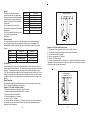
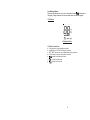
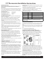
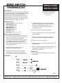
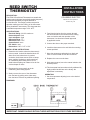
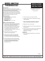
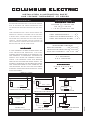
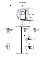
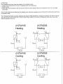
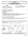
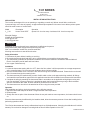
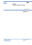
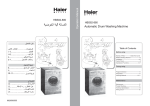
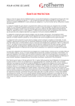
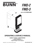
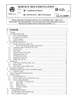
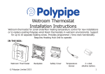
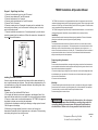
Diagram 3: Single Stage Heat Pump
1: Connect the transformer hot wire to the RC terminal.
2: Connect jumper between RC and RH terminals
3: Connect compressor to the Y terminal.
4: Connect jumper wire between the Y and W terminals.
5: Connect Fan to G terminal
6: Connect reversing valve to O terminals if reversing valve is activated in the
cool mode (most common), or to the B terminal if reversing valve is to be activated in the heating model.
7: Connect transformer common wire to C terminal (optional) if you wish thermostat to be powered from the transformer. Without this connection, thermostat will
be powered from AAA batteries.
Y RC RH W C
B
The TE8001 is an electronic non-programmable thermostat. It is designed to work with most
standard single stage heating and/or single stage cooling systems. These include single or dual
transformer 24 VAC gas, oil or electric heating, and 24 VAC cooling systems. This thermostat
is also compatible with single stage heat pumps.
The TE8001 is designed to operate entirely on two AAA alkaline batteries, or 24 volts from the
heating/cooling system’s transformer, using the batteries only for memory back up.
Installation:
Important: Read the entire instructions before beginning installation. Failure to follow these
instructions could result in personal injury and/or property damage.
Location:
WIRING DIAGRAM 3.
G
TE8001 Installation & Operation Manual
O
The thermostat should be mounted 4 to 5 feet above the floor in a location where it will be
exposed to average room temperature. The thermostat must not be mounted where it will be
effected by a source of heat such as lamps, sunlight, fireplaces, pipes, registers, etc..., or
sources of cold such as windows, doors, drafts, etc... The thermostat must not be mounted on
an exterior wall, behind a door, or in an alcove. Such locations will inhibit the thermostat’s
ability to accurately control room temperature
Removing existing thermostat:
Caution:
Installing Thermostat onto base:
Once the wires have been connected to the base, and the options selected, it is
time to install thermostat onto the base. Close the battery compartment door. Do
not install batteries yet. Align the thermostat with base, and push together. Open
battery door and install batteries.
Operation:
1: Select Heat or Cool with Heat/Off/Cool Switch:
2: The display will indicate current room temperature, and display a flame if the
heat mode has been selected or a snow flake if the cool mode has been selected.
3: Press up or down arrow to set desired temperature. “SET TEMP” will appear in
the display to indicate you are setting the temperature.
4: Whenever the thermostat is activating the heating or cooling system, the word
“ON” will appear in the display.
5: Whenever you change modes (from heat to cool or cool to heat), the
thermostat will remember the last temperature set in that mode. The heat setting
and cooling setting do not have to be the same.
4
Power must be disconnected before removing existing wiring connections from thermostat to
prevent possible electrical shock and/or equipment damage. All wiring must conform to local
and national electrical codes and regulations.
1: Remove existing wiring by writing down each of the wire’s colors and the designation of the
terminals that they are connected to. If more than one wire has the same color, tag the wire
with some form of identification.
2: Remove wires from thermostat.
Mounting:
This thermostat may be mounted directly to the wall, by using the mounting screws supplied.
Remove base from front section, by opening battery door, remove batteries. Pull case apart.
To mount directly to a wall use holes located in top and bottom of case.
Pull wires through hole in center of case.
Do not depend upon the thermostat as the sole means
of disconnecting power when installing or servicing the product it is
controlling. Always disconnect power at the main circuit breaker as
described above. Failure to do so may result in fatal electric shock.
1
TPI Corporation, Johnson City, TN 37602
Tel: 423-477-4131, Fax:423-477-0545
FORM: 8063
Rev: -
Wiring:
The chart is a cross reference for
terminal functionality. No application
will require connections to all terminals.
If connecting to a single transformer
system, only the RC or RH terminals
will be used.
The C terminal is only used if the
thermostat is powered from the system
transformer.
The B & O terminals will only be used
for a single stage heat pump
application.
Terminal
G
Y
RC
RH
W
C
B
O
Description
Fan
Compressor
Cool Transformer
Heat Transformer
Heat
Transformer Common
Heat Reversing Valve
Cool Reversing Valve
Option Jumpers:
The option jumpers are located to the right edge of the circuit board, directly
above the white relay. These jumpers are set at the time of installation. The
following table lists the 4 options. The factory settings are in bold. The options
include:
Option
C
1F
HBY
CBY
Jumper On
Celsius
Closer Differential
No Heat Delay
No Cool Delay
Jumper Off
Fahrenheit
Wider Differential
5Min. Delay
5Min. Delay
Fan Option:
An additional option jumper (J1) is located between the two switches, near the
bottom edge of the circuit board.. This selects fan operation for single transformer
systems: The factory setting has the jumper on the middle and lower two pins
(TH). This activates the fan whenever the thermostat turns the cooling on. For an
electric heat system, place the jumper on the middle and upper pins (H/C), which
will allow the fan to turn on whenever the thermostats turns on the cooling or the
heating.
Wiring Diagrams:
The following wiring diagrams illustrate how to connect the system wires to the
TE1001 thermostat depending on application:
Diagram 1: Four Wire Heat/Cool system.
1: Connect the transformer hot wire to the RH terminal.
2: Connect jumper between the RH and RC terminals.
3: Connect Heat to the W terminal.
4: Connect compressor to Y terminal.
5: Connect Fan to G terminal
6: Connect transformer common to C terminal (optional) if you wish thermostat to
be powered from the transformer. Without this connection, thermostat will be
powered from AAA batteries.
2
WIRING DIAGRAM 1.
G
Y RC RH W C
B
O
Diagram 2: Five Wire Heat/Cool system.
1: Connect the Cooling transformer hot wire to the RC terminal.
2: Connect the Heating Transformer hot wire to the RH terminal.
3: Connect Heat to the W terminal.
4: Connect compressor to Y terminal.
5: Connect Fan to G terminal
6: Connect cooling transformer common wire to C terminal (optional) if you wish
thermostat to be powered from the transformer. Without this connection, thermostat will be powered from AAA batteries.
WIRING DIAGRAM 2.
G
Y RC RH W C
3
B
O
Low Battery Indicator:
Whenever the batteries start to get low, a low battery indicator ‘
‘ will appear in
the display. Change batteries as soon as possible once the indicator appears.
LCD Pattern:
All Segments View
LCD Pattern Description:
a. 2 Large digits for room temperature readout.
b. 4 small bars for 0.2/0.4/0.6/0.8 degree indication.
c. “SET TEMP” indicator for control temperature setting indication.
d. “ON” indicator for output control status indication.
e. “
“ symbol for low battery indicate.
f. “
“ symbol for Heat mode.
g. “
“ symbol for Cool mode.
5
WARRANTY
Products manufactured by TPI Corporation are warranted to the original consumer to
be free from defects in material and workmanship for twelve (12) months from the
original date of purchase. The TPI warranty does not cover products modified outside
our factory, damage or failure caused by acts of God, abuse, misuse, connected to or
placed on other than rated voltage, abnormal usage, faulty installation, failure to follow
suggested maintenance procedures enclosed with the product, improper maintenance
or any repairs other than those provided by an authorized TPI Corporation service
center.
There are no obligations or liabilities on the part of the corporation for consequential
damages arising out of, or in connection with, the use or performance of the product,
or other indirect damages with respect to loss of property, revenues, or profit, or costs
of removal, installation or reinstallation.
All implied warranties with respect to TPI products, including implied warranties for
merchantability and implied warranties for fitness, are limited in duration to twelve
(12) months from original date of purchase, except those products or parts of products
which are warranted for longer periods. On such products or parts of products all
implied warranties for merchantability and fitness are limited to the duration of the
extended warranty period thereon.
Some states do no allow the exclusion or limitation of incidental or consequential
damages and some states do not allow limitations on how long an implied warranty
lasts. The above exclusions or limitations may not apply to you.
During the warranty period, TPI Corporation will, at its sole option, repair or replace
any defective parts or products returned, freight prepaid, to the TPI Corporation factory
or such other location as TPI Corporation may designate. Returned products must be
packaged carefully and TPI Corporation shall not be responsible for damage in transit.
When returning parts, the owner must provide the model number of the product and
nature of difficulty being experienced. This warranty does not obligate TPI Corporation
to bear the cost of labor in replacing any assembly, unit or component part thereof,
nor does the company assume any liability for secondary charges, expenses for
installing or removal, freight or damages. There will be charges rendered for product
repairs made after out warranty period has expired. Proof of purchase, including
date, must accompany request for in-warranty service. In any event, TPI Corporation’s
maximum liability shall not in any case exceed the list price for the product claimed to
be defective. This warranty gives to you specific legal rights and you may have other
rights, which may vary, from state to state. For the name of you nearest authorized
TPI Corporation service center, please write to TPI Corporation, P.O. Box 4973, Johnson
City, Tennessee, 37602.
In addition to the Limited Warranty stated above covering general products, TPI
Corporation extends this warranty on the following listed products, which are warranted
to the original consumer from the original date of purchase for the total time periods
indicated herein below:
Heating Products
1. Elements in Baseboards
2. All Other Heating Products
3. Thermostats and Controls
10 years
1 year
2 years
6
Manual For
TE8001 Thermostat
TPI Corporation
PO Box 4973Johnson City, TN 37602
Tel: 423-477-4131, Fax:423-477-0545
www.tpicorp.com
UT Thermostats Installation Instructions
Installation Instructions:
Please read all the instructions carefully before starting. Leave this
instruction sheet near the thermostat when you are finished.
Specifications:
For use with self-powered 250-750 millivolt generating systems and 2
wire (UT1001, Heating Only), or 3 wire and 6 wire (UT3001, Cooling
Only and UT8001, Heat/Cool) electric, gas or oil systems equipped
with 24 VAC controls.
Electrical Rating: 24-30 VAC
(or 250-750mV)
Heat Anticipator: 0.1A to 1.0A
(Adjustable)
Cool Anticipator: 0 to 1A
(Fixed)
Selecting Thermostat Location:
For accurate temperature control and comfort, selecting the proper
location is very important.
If this is a new installation, the guidelines listed below should be
followed. When replacing an old thermostat install the new
thermostat in the same location unless these guidelines suggest
otherwise.
1: Locate the thermostat on an inside wall of a frequently occupied
area (ie: family room) about 4-5 feet above the floor.
2: Do not install the thermostat where there are unusual sources of
“heat”, such as direct sunlight, or near a radiator, duct vent, lamp, or
fireplace.
3: Do not install the thermostat where there are unusual “cooling”
sources , such as an outside wall, drafts from doors, windows,
stairways, or duct vents.
4: Do not install the thermostat where the air circulation is poor, such
as in a corner, alcove or behind a door.
Removing Old Thermostat:
1: Shut off electricity to your heating and/or cooling system by
removing the associated fuse or switching the circuit breaker off.
2: Remove the cover of the old thermostat. If you do not see the
system wires, then you will have to remove another section of the
thermostat. This may require the use of a screwdriver.
3: Observe the terminal markings of each wire. Label each wire with
tape indicating the appropriated terminal markings to allow easy
installation of the UT thermostat.
4: After you have labeled the existing wires, remove the wires from the
terminals.
5: Remove the old thermostat base from the wall.
Installing the UT thermostat:
1: Hold the UT thermostat in one hand. Carefully remove cover from
the thermostat base by pulling upward gently. Remove any shipping
material present.
2: Position thermostat base on wall and carefully feed existing wires
through opening. The UT can be position horizontally or vertically. If
to be installed in the horizontal position, the adjustment lever must
extend out the right side of the thermostat. If installed in the vertical
position the lever must extend out the bottom of the thermsotat.
3: After you have finished locating the UT thermostat, you can mark
the placement of the two screw holes for mounting. Set aside
thermostat base.
4: If you are mounting the thermostat on plasterboard or another type
of soft material, use plastic anchors. Use a 3/16" drill to make two
holes where the mounting holes have been marked. Insert anchors
into holes.
5: Feed the wires back through the base, then mount to the wall with
supplied screws.
5: Connect the wires to their associated marked terminals. (See Chart
if old and new terminals do not match exactly)
7: Check all connections so that adjacent wires are not touching.
8: Replace cover onto base by snapping it into place.
9: Make sure the system switch is in the OFF position until you are
ready to check your wiring.
Old Thermostat
New Label
Description
M, 4, RH, R5, or 5 RH or R
Transformer Hot for Heat.*
V, or RC
RC or R
Transformer Hot for Cool.*
H, W, or 4
W
Heating Control (valve, relay, etc.)
Y, or Y6
Y
Cooling Control (valve, relay, etc.)
F or G
G
Fan Control. (See internal fan option)
* For separate RH and RC wires, you must remove the factory
installed J2 jumper.
Internal Fan Option (UT8001 only)
For typical gas or oil heating systems, place the J1 jumper on the G/O
pins to allow natural system delay in fan operation during the heat
mode.
If the heating system requires the fan to come on immediately with the
heat (ie: electric heating systems), then place the J1 Jumper on teh E
pins.
G/O – Fan turned on by heating system.
E – Fan turned on by thermostat in heat mode.
Setting the Heat Anticipator: (UT1001 & UT8001 models)
To help provide accurate control of furnace heat cycles, you must
adjust the anticipator setting of the UT thermostat to match the
current rating of the system control device. For Millivolt operation
the heating anticipator setting must be place over the MV.
This setting can be found by looking at the setting used on the
previous thermostat. If you are unable to find it, the information can
be found in the owner’s manual for the heating system. You can also
find the information printed on the control device at the furnace. The
control device is normally a gas valve, relay or pilot generator
located behind the furnace cover.
If the current rating is still unavailable, connect an AC amp meter
between the RH and W terminals on the thermostat. Let the system
operate through the amp meter for at least one minute before taking
the reading. The reading can then be used as the setting for the
anticipator.
Columbus Electric Division of TPI, PO Box 4973, Johnson City, TN 37602: Tel 800-251-7828, Fax 423-477-0545: REV120303
Check the wiring:
CAUTION DO NOT jump across the gas valve or relay to test the
thermostat. This will destroy the thermostat and void the warranty.
Heating Only Model: (UT1001)
1: Turn on power to the heating system.
2: Adjust the temperature setting on the thermostat to 6o to 8o F above
the room temperature. The heating system should turn on. The fan
may take a few minutes to turn on depending on the delay built into
the furnace.
5: Adjust the temperature setting of the thermostat 6o to 8o F below
the room temperature. The heating system should turn off. The fan
may have a delay before it turns off.
Cooling Only Model: (UT3001)
1: Turn on power to the Air conditioning system.
2: Place the Cool/Off switch to the Cool position.
3: Adjust the temperature setting on the thermostat to 6o to 8o F below
the room temperature. The A/C system should turn on. There may be
a short delay (typically 20 seconds) before the fan will turn on.
4: Adjust the temperature setting of the thermostat 6o to 8o F above
the room temperature. The A/C system should turn off. The fan may
have a delay before it turns off.
Heating & Cooling Model: (UT8001)
1: Turn on power to the heating/cooling system.
2: Place Heat/Off/Cool switch to the Heat position.
3: Adjust the temperature setting on the thermostat to 6o to 8o F above
the room temperature. The heating system should turn on. The fan
may take a few minutes to turn on depending on the delay built into
the furnace.
4: Adjust the temperature setting of the thermostat 6o to 8o F below
the room temperature. The heating system should turn off. The fan
may have a delay before it turns off.
Caution: To avoid damage to the air conditioner, do not operate if the
outside temperature is below 50 degrees. Please refer to the
recommendations of the air conditioner’s manufacturer.
5: Place the Heat/Off/Cool switch to the Cool position.
6: Adjust the temperature setting on the thermostat to 6o to 8o F below
the room temperature. The A/C system should turn on. There may be
a short delay (typically 20 seconds) before the fan will turn on.
7: Adjust the temperature setting of the thermostat 6o to 8o F above
the room temperature. The A/C system should turn off. The fan may
have a delay before it turns off.
Wiring Diagrams:
Columbus Electric Division of TPI, PO Box 4973, Johnson City, TN 37602: Tel 800-251-7828, Fax 423-477-0545:
REV120303
REED SWITCH
THERMOSTAT
DESCRIPTION:
The UT5001 Reed Switch Thermostat is a versatile low
voltage control utilizing a hermetically sealed (dust proof)
reed switch operated by a magnet attached to
a coiled bimetal. This design provides snap action
operation making precise leveling of the thermostat
during installation unnecessary. This thermostat has
a standard temperature range of 50 - 90OF.
SPECIFICATIONS:
Electrical Rating: 30 VAC maximum
Heat anticipator: fixed
Cool anticipator: fixed
Differential Heat: 1OF
Differential Cool: 1.5OF
System Switch: none
Fan Switch: none
Dimensions: 5.00” x 3.27” x 1.50”
INSTALLATION INSTRUCTIONS:
1. Determine the location where the thermostat is
to be mounted. It should be installed about 54”
above floor level where there is good air
circulation. Avoid heat sources such as lamps,
direct sunlight, fireplaces or walls containing
air conditioning and heating ducts. Do not
install where anything can obstruct free air flow
such as drapes or doors.
2. Disconnect the power supply to the air
conditioning and heating system.
3. Gently remove the cover of the thermostat
from the base by pulling at the sides away
from the base. Remove any additional packing.
INSTALLATION
INSTRUCTIONS
COLUMBUS ELECTRIC
a division of TPI Corporation
Johnson City, TN
4. Feed electrical wires from the system through
the two holes above the screw terminals. Wiring
must not interfere with the operation of the
thermostat. Use electrical material approved
by applicable codes.
5. Connect the wires to the proper terminals.
6. Install the thermostat on the wall with the mounting
screws provided.
7. Move the temperature adjusting lever back and
forth to insure bimetal is free from restictions.
8. Replace the cover onto the base.
9. With power restored, move the manual switch to the
desired position.
10.This thermostat has been electronically calibrated by
highly qualifed technicians at the factory. No
adjustment is necessary.
OPERATION:
1. Set the temperature adjusting lever to the desired
temperature.
DIAGRAMS:
O
B
R
Y
G
Rev.Form 8065
IMPORTANT: OWNER SHOULD RETAIN THESE INSTRUCTIONS FOR FUTURE REFERENCE
REED SWITCH
THERMOSTAT
DESCRIPTION:
The UT6001 Reed Switch Thermostat is a versatile low
voltage control utilizing a hermetically sealed (dust proof)
reed switch operated by a magnet attached to
a coiled bimetal. This design provides snap action
operation making precise leveling of the thermostat
during installation unnecessary. This thermostat has
a standard temperature range of 50 - 90OF.
SPECIFICATIONS:
Electrical Rating: 30 VAC maximum
Heat anticipator: fixed
Cool anticipator: fixed
Differential Heat: 1OF
Differential Cool: 1.5OF
System Switch: none
Fan Switch: none
Dimensions: 5.00” x 3.27” x 1.50”
INSTALLATION INSTRUCTIONS:
1. Determine the location where the thermostat is
to be mounted. It should be installed about 54”
above floor level where there is good air
circulation. Avoid heat sources such as lamps,
direct sunlight, fireplaces or walls containing
air conditioning and heating ducts. Do not
install where anything can obstruct free air flow
such as drapes or doors.
2. Disconnect the power supply to the air
conditioning and heating system.
3. Gently remove the cover of the thermostat
from the base by pulling at the sides away
from the base. Remove any additional packing.
INSTALLATION
INSTRUCTIONS
COLUMBUS ELECTRIC
a division of TPI Corporation
Johnson City, TN
4. Feed electrical wires from the system through
the two holes above the screw terminals. Wiring
must not interfere with the operation of the
thermostat. Use electrical material approved
by applicable codes.
5. Connect the wires to the proper terminals.
6. Install the thermostat on the wall with the mounting
screws provided.
7. Move the temperature adjusting lever back and
forth to insure bimetal is free from restictions.
8. Replace the cover onto the base.
9. With power restored, move the manual switch to the
desired position.
10.This thermostat has been electronically calibrated by
highly qualifed technicians at the factory. No
adjustment is necessary.
OPERATION:
1. Set the temperature adjusting lever to the desired
temperature.
DIAGRAMS:
Rev.Form 8064
IMPORTANT: OWNER SHOULD RETAIN THESE INSTRUCTIONS FOR FUTURE REFERENCE
REED SWITCH
THERMOSTAT
DESCRIPTION:
The UT9001 Reed Switch Thermostat is a versatile
millivolt control utilizing a hermetically sealed (dust proof)
reed switch operated by a magnet attached to
a coiled bimetal. This design provides snap action
operation making precise leveling of the thermostat
during installation unnecessary. This thermostat has
a standard temperature range of 50 - 90OF.
SPECIFICATIONS:
Electrical Rating: 250 - 750 millivolt
Differential Heat: 1OF
System Switch: none
Fan Switch: none
Dimensions: 5.00” x 3.27” x 1.50”
INSTALLATION INSTRUCTIONS:
1. Determine the location where the thermostat is
to be mounted. It should be installed about 54”
above floor level where there is good air
circulation. Avoid heat sources such as lamps,
direct sunlight, fireplaces or walls containing
air conditioning and heating ducts. Do not
install where anything can obstruct free air flow
such as drapes or doors.
2. Disconnect the power supply to the air
conditioning and heating system.
3. Gently remove the cover of the thermostat
from the base by pulling at the sides away
from the base. Remove any additional packing.
INSTALLATION
INSTRUCTIONS
COLUMBUS ELECTRIC
a division of TPI Corporation
Johnson City, TN
5. Connect the wires to the proper terminals.
6. Install the thermostat on the wall with the mounting
screws provided.
7. Move the temperature adjusting lever back and
forth to insure bimetal is free from restictions.
8. Replace the cover onto the base.
9. With power restored, move the manual switch to the
desired position.
10.This thermostat has been electronically calibrated by
highly qualifed technicians at the factory. No
adjustment is necessary.
OPERATION:
1. Set the temperature adjusting lever to the desired
temperature.
4. Feed electrical wires from the system through
the two holes above the screw terminals. Wiring
must not interfere with the operation of the
thermostat. Use electrical material approved
by applicable codes.
Rev.Form 8068
IMPORTANT: OWNER SHOULD RETAIN THESE INSTRUCTIONS FOR FUTURE REFERENCE
COLUMBUS ELECTRIC
INSTALLATION & INSTRUCTION SHEET
LINE VOLTAGE THERMOSTAT - ET SERIES
DESCRIPTION
SPECIFICATIONS
ELECTRICAL R
ATING
RA
The Columbus Electric Wall Line Voltage Thermostat is suitable for direct connection with
any resistance heating elements and unit heaters.
22 AMPS @ 125/277 VAC
3/4 HP @ 125 VAC
1 1/2 HP @ 250/277 VAC
DIFFERENTIAL
This thermostat has a snap action switch operated by a bimetal actuator and is available
in single pole, double pole with positive off,
two stage heat, cooling only and heat or cool
models. Other options include factory or
field installed locking kits for top and for
bottom setting and 6” wire leads.
WARNING
IF THIS PRODUCT IS USED TO REPLACE A DEVICE CONTAINING MERCURY, THE PURCHASER OR CONSUMER MUST ENSURE THAT
THE MERCURY IS PROPERLY MANAGED TO
COMPLY WITH STATE OR FEDERAL REGULATIONS. THE MERCURY MUST NOT BECOME
PART OF SOLID WASTE OR WASTE WATER. ADDITIONAL GUIDANCE MAY BE OBTAINED FROM
THE MANUFACTURER OF THE PRODUCT BEING REMOVED, OR BY CALLING COLUMBUS
ELECTRIC MANUFACTURING COMPANY MATERIALS MANAGER.
1-800-251-7828
HEAT APPROXIMATELY..........2OF
COOLING APPROXIMATELY....4OF
HEAT ANTICIPATOR MODEL...1/2OF
TEMPER
ATURE R
ANGE
TEMPERA
RANGE
(STANDARD MODELS)
SETTING RANGE..........50OF TO 90O
HEATING OR COOLING.50OF TO 90O
ATTIC FAN CONTROL...90OF TO 135O
APPRO
VALS
APPROV
U.L. APPROVED
C.S.A. CERTIFIED
DIMENSIONS
4 3/4 X 2 3/4 X 2 3/4
H
W
D
INST
ALL
ATION / OPER
ATION
INSTALL
ALLA
OPERA
LINE
LINE
LOAD
SPST
HEATING OR COOLING
NORM
OPEN
TERMINAL
NORM
CLOSED
TERMINAL
LINE
COOL LOAD
HEAT LOAD
LOAD
SPDT
HEATING OR COOLING
DPST HEATING
LINE
LINE
LINE
NO INTERNAL
CONNECTION IN
SWITCH
SPDT WITH
ANTICIPATION HEATING
P.O. BOX 4973
LOAD 2
TWO STAGE
HEATING & COOLING
LOAD
DPST WITH ANTICIPATION
HEATING
JOHNSON CITY, TN. 37602-4973
423-477-4131
8001
anticipator lead
LOAD 1
REV. G
LOAD
INSTALLATION AND OPERATION MANUAL
EPET SERIES EXPLOSION PROOF THERMOSTATS
The Columbus Electric EPET Series thermostat is designed to control heating only, cooling only,
heating and cooling or ventilation systems in oil refineries, grain elevators, munitions plants, hospital
operating rooms and other hazardous locations.
The switching mechanism is enclosed in a 1/2” thick cast aluminum case which is dust proof and dust
resistant. A reliable sensing element provides accurate response to temperature change and does not
require leveling during installation.
The casing is tapped top and bottom for 3/4” conduit. A 1/2” adapter is included.
SPECIFICATIONS
Electrical Ratings:
22 Amp @ 125 - 277 VAC
3/4 HP @ 125VAC
1 1/2 HP @ 250 - 277 VAC
Differential : Heat- 2°F / Cool- 4°F
Dimensions: 5.62” x 6.37” x 4.43”
Approvals: UL and CSA
Class I Groups C & D
Class II Groups E, F & G
Temperature adjustment range: 50-90°F
INSTALLATION
ALL WIRING MUST COMPLY WITH NFPA-70 (NEC), LOCAL AND STATE CODES.
Locate the thermostat approximately five feet (5’) above the floor in a location that will best sense the
average temperature of the area to be controled. Do not mount the thermostat adjacent to water pipes,
in drafty areas, or other locations that would adversely affect the operation of the thermostat.
1)
2)
3)
4)
5)
6)
Remove the thermastat cover assembly from the base by removing the four corner screws.
Set the cover assembly aside. CAUTION: Marring of the mating surfaces of the enclosure
could destroy the integrity of the seal causing unsafe conditions during thermostat
operation.
Mount the thermostat base on the surface selected. See Fig. 1 for dimensions.
The base is tapped for 3/4” conduit; a 1/2” conduit adapter and a 3/4” plug is provided.
Two threaded openings are provided for wiring. Unused openings must be properly plugged
with the plug provided prior to applying power to the unit.
Connect the conduit to the mounted base and pull the required wires into the base.
Connections are to be made to the switch terminals on the rear of the cover assembly. See
Fig. 2. The cover assembly can then be attached to the base using the four mounting screws.
TIGHTEN TO A MINIMUM OF 40 INCH POUNDS.
The installer must seal each conduit run within 18” of the thermostat enclosure. This seal
must be a suitable, listed hazardous location fitting.
FORM: 8069
REV. -
DIAGRAMS
FIG. 1
FIG. 2
TYPICAL WIRING DIAGRAMS
NC
COOL
NO
C
L1
L2
NC
HEAT
NC
L2
NO
NO
C
C
COOL
L1
L1
CHANGE *
OVER
SWITCH
NC
HEAT
COOL
NO
L2
C
L1
HEAT
CHANGE *
OVER
SWITCH
NC
NO
NC
C
NO
HEAT
COOL
C
L1
L2
L1
* TO BE PROVIDED BY OTHERS
L2
L2
L__Y-01 SERIES
TPI CORPORATION
PO BOX 4973
JOHNSON CITY, TN 37602
INSTALLATION INSTRUCTIONS
APPLICATION
The L series are designed for use as operating or regulating controls only. Where control failure could result
in personal injury or the loss of property, an approved backup temperature limit control or an advisory alarm system
should be used to warn of control failure.
Model
L__Y-01
Description
Heat or Cool SPDT
Operation
Opens N.C. circuit on temp. rise/closes N.O. circuit on temp rise.
Electrical Ratings
25 AMP @ 125/240/480 Vac
3/4 HP @ 125 Vac
1 1/2 HP @ 240 Vac
*CAUTION*
Installation must be performed by an experienced, qualified service person.
Always disconnect power supply before performing any work.
Wire nut or otherwise insulate any unused conductors.
All wiring must conform to state and local codes.
Safety Information
1. Disconnect all power before installing or servicing.
2. Be certain that the electrical load that is to be controled does not exceed the thermostat rating.
3. This thermostat is intended for permanent installation and must be installed in accordance with the National
Elecric Code (NEC) and all state and local codes.
4. Use copper conductors only.
Installation
1. Locate the thermostat sensing bulb 4 to 6 FT. above the floor, where it will be exposed to an average temperature
of the controlled space. Do not mount near windows, doors or direct sunlight.
2. Remove the thermostat cover. Position the box with the wiring hole oriented as desired. Fasten the box to the wall
with 2-3 screws through the mounting holes.
3. The thermostat may be installed using conduit, flexible cable or other code approved wiring methods. All fittings
and materials used should be approved for the application and should be installed in accordance with instructions.
4. Complete the wiring by attaching the thermostat leads in accordance to the applicable wiring diagram using wire
nuts (not provided). A green groung wire is provided to attach the line and equipment groung to the thermostat.
After the connections are made, all wires should be pushed back into the box.
5. The thermostat cover should now be attached to the box using the screw provided.
Operation
After installation and wiring, check the operation in the following manner:
1. Adjust the thermostat set point to about 10 degrees below room temperature.
2. Restore power.
3. Slowly raise the set point of the thermostat. When the set point reaches room temperature, the heater should come
on.
Since the thermostat may be afffected by the installers hand, allow the necessary amount of time after handling before
performing operation check.
The L Series thermostats are factory calibrated and require no field adjustments. Changing the calibration will void the
warranty. Do not bend or damage the sensing bulb as this will afffect operation of the unit.
FORM 8051 REV. A