1
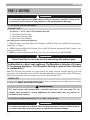
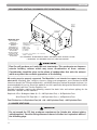
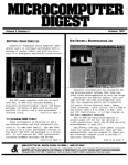
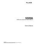
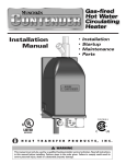
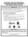
Installing, Operating & Maintaining
MUNCHKIN VWH HIGH EFFICIENCY
HOT WATER SUPPLY BOILER
WARNING
If the information in this manual is not followed exactly, a fire or explosion may
result causing property damage, personal injury or loss of life.
Do not store or use gasoline or other flammable vapors and
liquids in the vicinity of this or any other appliance.
WHAT TO DO IF YOU SMELL GAS
• Do not try to light any appliance.
• Do not touch any electrical switch: do not use any phone in
your building.
• Immediately call your gas supplier from a neighbor's phone.
Follow the gas supplier's instructions.
• If you cannot reach your gas supplier, call the fire department.
Installation and service must be performed by a qualified
installer, service agency or the gas supplier.
CONTROLS
MH27745
WARNING
This manual must only be used by a qualified heating installer / service
technician. Failure to comply could result in severe personal injury, death or
substantial property damage. It is also important to keep these Instructions
with the appliance.
HEAT TRANSFER PRODUCTS, INC.
120 BRALEY RD., E. FREETOWN, MA
02717
USING THIS MANUAL
USING THIS MANUAL
SPECIAL ATTENTION BOXES
Throughout this manual you will see these
special attention boxes similar to this one,
which are intended to supplement the
instructions and make special notice of
potential hazards. These categories mean, in
the judgement of Heat Transfer Products, Inc.:
DANGER
DANGER indicates an imminently hazardous
situation which, if not avoided, will result in
death or serious injury.
WARNING
WARNING indicates a potentially hazardous
situation which, if not avoided, could result in
death or serious injury.
CAUTION
CAUTION Indicates a potentially hazardous
situtation which, if not avoided, may result in
minor or moderate injury.
CAUTION
CAUTION used without the safety alert symbol
indicates a potentially hazardous situation which,
if not avoided, may result in property damage.
WARNINGS
• THIS UNIT IS FOR CATEGORY IV VENTING - 2 PIPE ONLY. THIS IS A SEALED
COMBUSTION APPLIANCE.
• THIS HEATER INSTALLATION MUST CONFORM TO THE LATEST EDITION OF THE
“NATIONAL FUEL GAS CODE” ANSI Z223.1 NEPA 54 AND OR CAN/CGA B149
INSTALLATION CODES. STATE AND LOCAL CODES MIGHT ALSO APPLY TO
INSTALLATION.
• WHERE REQUIRED BY THE AUTHORITY HAVING JURISDICTION, THE
INSTALLATION MUST CONFORM TO THE STANDARDS FOR CONTROLS AND
SAFETY DEVICES FOR AUTOMATICALLY FIRED HEATERS, ANSI/ASME HEATER
AND PRESSURE VESSEL CODE, Section IV, ALONG WITH CSD1.
• THE HEATER, GAS PIPING, WATER PIPING, VENTING AND ELECTRICAL MUST BE
INSTALLED BY TRAINED & QUALIFIED PERSONNEL FAMILIAR WITH
INSTALLATION PRACTICES, LOCAL CODE, LICENSING REQUIREMENTS.
• IF THE INFORMATION IN THESE INSTRUCTIONS ARE NOT FOLLOWED EXACTLY,
A FIRE OR EXPLOSION MAY RESULT; CAUSING PROPERTY DAMAGE, PERSONAL
INJURY, OR DEATH.
• DO NOT STORE OR USE GASOLINE OR OTHER FLAMMABLE VAPORS AND
LIQUIDS IN THE VICINITY OF THIS OR ANY OTHER APPLIANCE;
• THE USE OF A LOW WATER CUT-OFF DEVICE MAY BE REQUIRED BY STATE OR
LOCAL CODES IF THE MUNCHKIN IS INSTALLED ABOVE RADIATION LEVELS.
2
TABLE OF CONTENTS
TABLE OF CONTENTS
A
B
C
D
PART 1 . . . . . . . . . . . . . . . . . . . . . .4 thru 8
PART 6 . . . . . . . . . . . . . . . . . . . .29 thru 33
GENERAL INFORMATION
START UP PROCEDURES
How It Operates . . . . . . . . . . . . . . . . . .4
Munchkin Ratings and Dimensions . .5–7
Pre-installation Requirements . . . . . . .7
Pressure Relief Valve . . . . . . . . . . . . . .8
PART 2 . . . . . . . . . . . . . . . . . . . . . . . . . . . .9
ELECTRICAL
A
Electrical Connection . . . . . . . . . . . . . .9
A
B
C
D
E
F
G
H
Sequence of Operation . . . . . . . . . . .29
Items to be checked before
lighting the Munchkin . . . . . . . . . . . . .29
Lighting Instructions . . . . . . . . . . . . . .30
Operating Instructions . . . . . . . . . . . .30
Adjusting the Operating Set Points
of the Munchkin VWH Display . . . . . .30
Status Menu . . . . . . . . . . . . . . . . . . . .31
Test Mode . . . . . . . . . . . . . . . . . . . . . .31
To Turn Off Gas to Appliance . . . . . . .32
PART 3 . . . . . . . . . . . . . . . . . . . .10 thru 11
PART 7 . . . . . . . . . . . . . . . . . . . .34 thru 36
GAS CONNECTION
A
B
C
Gas Connection . . . . . . . . . . . . . . . . . .10
Gas Piping . . . . . . . . . . . . . . . . . . . . . .10
Gas Table . . . . . . . . . . . . . . . . . . . . . . .10
TROUBLESHOOTING
A
B
C
Munchkin Error Code . . . . . . . . . . . . .34
Boiler Error . . . . . . . . . . . . . . . . . . . . .34
Boiler Fault . . . . . . . . . . . . . . . . . . . . .34
PART 4 . . . . . . . . . . . . . . . . . . . .12 thru 18
PART 8 . . . . . . . . . . . . . . . . . . . .37 thru 41
VENTING
A
B
C
D
E
Approved Venting Materials . . . . . . . .12
Venting the Munchkin in
3”, 4” or 6” Plastic Pipe . . . . . . . . . . .12
Longer Vent Runs . . . . . . . . . . . . . . .14
Heater Removal from a
Common Vent System . . . . . . . . . . . .15
Condensate Removal . . . . . . . . . . . . .16
MAINTENANCE
A
B
C
D
E
Maintenance Procedures . . . . . . . . . .37
Annual Maintenance . . . . . . . . . . . . . .37
Condensate Cleaning Instructions . . .37
Combustion Chamber
Coil Cleaning Instructions . . . . . . . . . .38
Munchkin Controllers . . . . . . . . . . . . .39
PART 5 . . . . . . . . . . . . . . . . . . . .19 thru 29
PIPING
A
B
Expansion Tank . . . . . . . . . . . . . . . . . .19
High Velocity Circulator Pump . . . . . .19
3
GENERAL INFORMATION
PART 1. GENERAL INFORMATION
A. HOW IT OPERATES
The Munchkin VWH is a hot water supply boiler designed to operate in conjuction with a hot water
storage tank. Each Munchkin VWH is equipped with a high velocity pump to keep the unit running
efficiently for many years of service. A flow switch monitors the water flow through the heat exchanger
to make sure that the unit has an adequate flow rate during operation. The Munchkin VWH Controller
accurately monitors the return and supply temperature that controls the output range of the Munchkin
When the system has sensed a temperature drop below the set point and minus the differential set
point, The Munchkin VWH will activate the blower motor for a pre-purge of 5 seconds before going
into operation. Once in operation, the Munchkin controller will now start to modulate the pre-mix
burner based on analyzing the return, supply, differential and operating set point temperatures. By
compiling this information, the controller utilizes an algorithm to fully adjust the firing rate while
maintaining the desired output temperature. The pre-mix burner fan has direct drive current, lowvoltage motor with pulse relay counting. This system allows precise control over the fan speed and
combustion air volumes. Coupled with the fuel and air mixing system which are set to provide a one
to one ratio of precisely measured volumes of fuel to air, an accurate and instant burner output is
achieved. This keeps the Munchkin VWH running at the highest efficiency.
RECOMMENDED SERVICE CLEARANCES
Figure 1-1
4
GENERAL INFORMATION
B. MUNCHKIN RATINGS AND DIMENSIONS
Model
Input
Modulation
Output
Modulation
Supply/Return Gas Connection Intake/Exhaust Shipping
Connection
Size
Dia.
Weight
L
W
H
199VWH 66,000–199,000 48,000–191,040
1¼” NPT
¾”
3” PVC Sch. 40
126 lbs.
24.50 18.25 25.88
399VWH 100,000–399,000 96,000–343,040
2” NPT
1¼”
4” PVC Sch. 40
267 lbs.
44.25 18.25 25.88
FIRST HOUR RATING
FIRST HOUR RATING
W/ 80 GAL. STORAGE TANK W/ 119 GAL. STORAGE TANK
MODEL INLET OUTLET RECOVERY RATE
199 VWH
40°
80°
561 GAL
614 GAL
640 GAL
199 VWH
40°
90°
450 GAL
503 GAL
529 GAL
199 VWH
40°
100°
374 GAL
427 GAL
453 GAL
199 VWH
40°
110°
320 GAL
373 GAL
399 GAL
199 VWH
40°
120°
280 GAL
333 GAL
359 GAL
199 VWH
40°
130°
250 GAL
303 GAL
329 GAL
199 VWH
40°
140°
224 GAL
277 GAL
303 GAL
199 VWH
40°
150°
205 GAL
258 GAL
284 GAL
199 VWH
40°
160°
188 GAL
241 GAL
267 GAL
199 VWH
40°
170°
173 GAL
226 GAL
252 GAL
199 VWH
40°
180°
160 GAL
213 GAL
239 GAL
399 VWH
40°
80°
1125 GPH
1178 GAL
1204 GAL
399 VWH
40°
90°
900 GPH
953 GAL
979 GAL
399 VWH
40°
100°
750 GPH
803 GAL
829 GAL
399 VWH
40°
110°
642 GPH
695 GAL
721 GAL
399 VWH
40°
120°
562 GPH
615 GAL
641 GAL
399 VWH
40°
130°
500 GPH
553 GAL
579 GAL
399 VWH
40°
140°
450 GPH
503 GAL
529 GAL
399 VWH
40°
150°
409 GPH
462 GAL
488 GAL
399 VWH
40°
160°
375 GPH
428 GAL
454 GAL
399 VWH
40°
170°
346 GPH
399 GAL
425 GAL
399 VWH
40°
180°
321 GPH
374 GAL
400 GAL
199 VWH at 20GPM
Pressure Drop for Tube Length of 1¼” Copper
(10) 90° Elbows ad (2) Tees (Side Outlet)
with Munchkin 199 VWH
399 VWH at 40GPM
Pressure Drop for Tube Length of 2” Copper
(10) 90° Elbows and (2) Tees (Side Outlet)
with Munchkin 399 VWH
1¼” Tube Length
20’
30’
40’
50’
60’
2” Tube Length
20’
30’
40’
50’
60’
20 GPM
21.65
22.62
23.6
24.56
25.53
40 GPM
24
24.37
24.74
25.11
25.48
5
GENERAL INFORMATION
DIMENSIONS
Figure 1-2
6
GENERAL INFORMATION
Figure 1-3
C. PRE-INSTALLATION REQUIREMENTS
GENERAL
1. Munchkin VWH is supplied completely assembled as a packaged boiler. The package should
be inspected for damage upon receipt and any
damage to the unit should be reported to the
shipping company and wholesaler. This boiler
should be stored in a clean, dry area.
2. Carefully read these instructions and be sure
to understand the function of all connections
prior to beginning installation. Contact your
Heat Transfer Products, Inc. Representative or
the Heat Transfer Products, Inc. Customer
Service Department for help in answering
questions.
3. This boiler must be installed by a qualified
contractor. The boiler warranty may be voided
if the boiler is not installed correctly.
CODES & REGULATIONS
Installation and repairs are to be performed in strict
accordance with the requirements of state and local
regulating agencies and codes dealing with boiler
and gas appliance installation.
WARNING
Liquefied Petroleum (LP) Gas or Propane is
heavier than air and, in the event of a leak, may
collect in low areas such as basements or floor
drains. The gas may then ignite resulting in a
fire or explosion.
ACCESSIBILITY CLEARANCES
1. The Munchkin VWH is certified for closet
installations with zero clearance to com-
bustible construction. In addition, it is design
certified for use on combustible floors.
2. Refer to Figure 1.1 for the recommended clearance to allow for reasonable access to the boiler. Local codes or special conditions may
require greater clearances.
CAUTION
Do not install this boiler on carpeting.
COMBUSTION AND VENTILATION AIR
1. The Munchkin VWH is designed only for operation with combustion air piped from outside
(sealed combustion). PVC pipe must be supplied between the air inlet connection at the
rear of the boiler through an outside wall.
2. No additional combustion or ventilation air is
required for this appliance.
3. Refer to Section 4 of this manual, Venting, for
specific instructions for piping combustion air.
PLANNING THE LAYOUT
1. Prepare sketches and notes showing the layout of the boiler installation to minimize the
possibility of interferences with new or existing equipment, piping, venting and wiring.
2. The following sections of this manual should
be reviewed for consideration of limitations
with respect to:
a. Electrical Wiring: Part 2
b. Gas Connection: Part 3
c. Venting: Part 4
f. Piping the Munchkin VWH to the
Storage Tank: Part 5
7
GENERAL INFORMATION
WARNING
The Munchkin is certified as an indoor appliance. Do not install the Munchkin
outdoors or locate where it will be exposed to freezing temperature. This includes all
related piping and components. If the Munchkin is subjected to flood water or
submersed in water, the Munchkin must be replaced.
NOTICE
Service clearance of the Munchkin
1. The front of the appliance needs 24" of clearance for service minimum. It may have
a non-rated or combustible door or access panel and must have a minimum of 24"
clearance.
2. The left side of the heater is 12" clearance
3. The right side of the heater is 12" clearance
4. The top of the heater is 15" clearance.
If the Munchkin is set up for liquefied petroleum (LP) gas, some geographic areas follow the Uniform
Mechanical Code, section 304.6, “Liquefied petroleum gas burning appliances shall not be installed in
a pit, basement or similar location where heavier-than-air gas might collect. Appliances so fueled, shall
not be installed in a below grade under-floor space or basement unless such location is provided with
an approved means for removal of unburned gas.”
NOTICE
Condensation removal: This is a condensing, high efficiency appliance, therefore
condensation removal must be addressed to avoid damage to surrounding area or
appliance. See Part (4) for Condensate Requirements.
D. PRESSURE RELIEF VALVE
A pressure relief valve is installed into the right front side of the manifold. It is required that it meets
the requirements of ANSI/ASME Boiler and Pressure Vessel Code, Section IV or CSA B51: Boiler
Pressure Vessel and Piping Code as applicable for heating boilers. A ¾” pipe connected to the pressure
relief valve must be directed to a floor drain or suitable location within 6” of a drain or floor. To protect
the valve from freezing, do not plug or cap the pressure relief valve.
DANGER
Serious explosion causing property damage and/or loss of life could result. Under no
circumstances should the relief valve be eliminated, capped or plugged.
8
ELECTRICAL
PART 2. ELECTRICAL
A. ELECTRICAL CONNECTION
The electrical connection for the Munchkin is on the left hand side of the unit. There is a ½” knockout
location for an electrical connection for both the incoming power and the circulator connection. All
electrical wiring must be performed by a qualified licensed electrician in accordance with National
Electrical Code ANSI/NEPA to and/or the Canadian Electrical Code, Part 1 CSA C22.1, or to the
applicable codes and standards. For your convenience, we have labeled all the wires that need to be
connected to operate the Munchkin.
The electrical requirements are for standard 120 volts, 60 Hz 15 Amp service. This unit is wired with
#18 awg and fused for no more than 15 Amps.
DANGER
IT IS EXTREMELY IMPORTANT THAT THIS UNIT BE PROPERLY GROUNDED!
DANGER
IT IS VERY IMPORTANT THAT THE BUILDING GROUND IS INSPECTED BY A
QUALIFIED ELECTRICIAN PRIOR TO MAKING THIS CONNECTION!
There are two ground points in the electrical compartment that must be connected to the building
ground system. Connect the building ground to the green ground screw and the green ground wire
inside electrical box provided.
The Incoming power supply is connected to the Black (Hot) and the White (Neutral).The Munchkin
Control board is polarity sensitive. If the polarity is reversed, the Munchkin control will not sense a
flame and lock out the system.
It is important that the electrical power is not turned on at this time. Double check all connections and then
turn the power on. The display that is provided with the Munchkin should now be reading the outlet
temperature. Note: see Part 6/Startup Procedure section in the manual to change the temperature setting
or run the heater.
9
GAS CONNECTION
PART 3. GAS CONNECTION
WARNING
Failure to follow all precautions could result in fire, explosion or death!
A. GAS CONNECTION
The gas supply shall have a maximum inlet pressure of less than 14” water column (350 mm), ½ pound
pressure (3.5 kPa), and a minimum of 7” water column. The entire piping system, gas meter and
regulator must be sized properly to prevent pressure drop greater than 0.5” as stated in the National
Fuel Gas Code. This information is listed on the rating plate. It is very important that you are
connected to the type of gas as noted on the rating plate. “LP” for liquefied petroleum, propane gas
or, “Nat” natural or city gas. All gas connections must be approved by the local gas supplier, or utility
in addition to the governing authority, prior to turning the gas supply on. The nipple provided for the
399VWH is 11/4” with a mandatory 1 x 11/4 reducing coupling (provided). Threaded into the branch of
a 11/4” tee and a drip leg fabricated as per the national fuel gas code. The 199VWH has a 3/4” gas supply
nipple with a 1/2 x 3/4 reducing coupling (provided) which is to be threaded into the branch of a 3/4” tee.
You must ensure that the entire gas line to the connection at the Munchkin is no smaller than 11/4”
for the 399VWH and 3/4” for the 199VWH. Once all the inspections have been performed, the piping
must be leak tested. If the leak test requirement is a higher test pressure than the maximum inlet
pressure, you must isolate the Munchkin from the gas line. In order to do this, you must shut the gas
off using factory and field-installed gas cocks (following the lighting instructions in Part 6 Section B.)
This will prevent high pressure. Failure to do so may damage the gas valve. In the event the gas valve
is exposed to a pressure greater than 1/2 PSI, 14” water column, the gas valve must be replaced. Never
use an open flame (match, lighter, etc.) to check gas connections.
B. GAS PIPING
1. Run the gas supply line in accordance with all applicable codes.
2. Locate and install manual shutoff valves in accordance with state and local requirements.
C. GAS TABLE
Refer to Table (1) to size the supply piping to minimize pressure drop between meter or regulator
and unit.
Maximum Capacity of Pipe in Cubic Feet of Gas per Hour for Gas Pressures of 0.5 psi or Less and a
Pressure Drop of 0.3 Inch water Column
(TABLE 1)
Nominal
Iron Pipe Internal
Size
Diameter
(inches) (inches) 10
3/4
.824
278
1
1.049
520
1 1/4
1.380 1,050
1 1/2
1.610 1,600
10
(Based on a 0.60 Specific Gravity Gas)
Length of Pipe (Feet)
20
190
350
730
1,100
30
152
285
590
890
40
130
245
500
760
50
115
215
440
670
60 70
105 96
195 180
400 370
610 560
80
90
170
350
530
90
84
160
320
490
100
79
150
305
460
125
72
130
275
410
150
64
120
250
380
175
59
110
225
350
200.
55}
100}
210}
320}
BTU'S
PER
HOUR
X 1,000
GAS CONNECTION
It is recommended that a soapy solution be used to detect leaks. Bubbles will appear on the pipe to
indicate a leak is present. The gas piping must be sized for the proper flow and length of pipe, to
avoid pressure drop. Both the gas meter and the gas regulator must be properly sized for the total
gas load. If you experience a pressure drop greater than 1" WC, the meter, regulator or gas line is
undersized or in need of service. You can attach a manometer to the incoming gas drip leg, by
removing the cap and installing the manometer. The gas pressure must remain between 7" and 14"
during stand-by (static) mode and while in operating (dynamic) mode. If an in-line regulator is used,
it must be a minimum of 10 feet from the Munchkin. It is very important that the gas line is properly purged by the gas supplier or utility. Failure to properly purge the lines or improper line sizing, will result in ignition failure. This problem is especially noticeable in NEW LP installations and
also in empty tank situations. This can also occur when a utility company shuts off service to an area
to provide maintenance to their lines. This gas valve must not be replaced with a conventional gas
valve under any circumstances. As an additional safety feature, this gas valve has a flanged connection to the Venturi and blower.
WARNING
Failure to follow all precautions could result in fire, explosion or death!
11
VENTING
PART 4. VENTING
DANGER
It is extremely important to follow these venting instructions carefully. Failure to do
so can cause severe personal injury, death or substantial property damage.
A. APPROVED VENTING MATERIALS
EXHAUST VENT
Use Plastic 3” and 4” and 6” Pipe Schedule 40 or 80.
1. Non-Foam Core PVC Pipe
2. Non-Foam Core CPVC Pipe
3. Non-Foam Core ABS Pipe
Vent Piping must conform to following
1. PVC Non Foam Core Pipe (Polyvinyl Chloride) to ASTM D-1784 Class 12454-B, Formerly designated Type 1, Grade 1.
2. CPVC (Chlorinated Polyvinyl Chloride) Class 23447-B, Formerly designated Type IV, Grade 1 conforming to ASTM D-1784.
3. ABS (Acrylonitrile-Butadiene-Styrene) Class 3-2-2-2-2 conforming to ASTM D3965.
DANGER
Foam Core Pipe is not to be used in connecting the exhaust pipe.
The Munchkin is a direct vent appliance. The Munchkin is listed as a Category
IV Condensing Appliance. (The Munchkin Venting is rated at Zero Clearance
to combustibles.)
Note: For Concrete construction or to meet certain fire codes, exhaust and inlet piping at the wall
penetration to the Munchkin must be CPVC Schedule 40 or 80 to meet local fire codes. The balance
from the penetrated wall to the outside, may be PVC Schedule 40 or 80.
INTAKE VENT
Use the same material as used for exhaust. Plastic Pipe or Cellular Foam Core Pipe may be used for
the inlet only, NEVER ON EXHAUST PIPING!
WARNING
This vent system will operate with a positive pressure in the vent pipe. Do not
connect vent connectors serving appliances by natural draft into any portion of
mechanical draft systems.
B. VENTING THE MUNCHKIN VWH IN 3”, 4” OR 6” PLASTIC PIPE
DANGER
It is extremely important to follow these venting instructions exactly. Failure to do so
can cause severe personal injury, death or substantial property damage.
12
VENTING
NOTICE
The following are code restrictions for the location of the flue gas vent terminal.
Compliance to these requirements doesn’t insure a satisfactory installation; good
common sense must also be applied. It is important to make sure that exhaust gases
are not recirculated into the inlet air of the Munchkin VWH.
The inlet pipe on the back of the cabinet is 3" for the 199 VWH and 4" for the 399 VWH. It is very
important that you plan the location properly to eliminate long pipe runs and excessive fittings. Inlet
pipe size must not be reduced. Do not combine the inlet air with any other inlet pipe including an
inlet to an additional similar appliance. The joints must be properly cleaned, primed and cemented.
The piping must also be properly supported as per Local and National Standard Plumbing Codes. It
is important that the piping must be clean and free from burrs, debris, ragged ends and particles of
PVC.
Exhaust piping should be sloped back to the connection on the Munchkin, at least ¼" per foot to
remove additional condensate that forms within the pipe. The total combined length of pipe (intake
piping plus exhaust piping added together) including elbow allowances for intake and exhaust (each
elbow = 5' of pipe) should not exceed 85'. The combined vent length should not be less than a combined length of 6' plus two 90 degree elbows. Choose your vent termination locations carefully. You
must also make certain that exhaust gas does not re-circulate back into the intake pipe. You must
place them in an open area and follow the guidelines below.
1) Never vent into a walkway, patio area, alley or otherwise public area less than 7' from the
ground. (See detail below references Fig. A.10.8 in the National Fuel Gas Code 2002 “Exit
Terminals of Mechanical Draft and Direct-Venting Systems”.)
2) Never vent over or under a window or over a doorway where the exhaust plume or condensation liquid will cause obtrusive or dangerous conditions. (Or refer to National Fuel Gas
Code, CAN B149)
3) Never install a heat saver or similar product to capture waste heat from exhaust.
4) Always have a vent location at least 1' above maximum snow level.
5) Always have vent 1' above ground level, away from shrubs and bushes.
6) Follow local gas codes in your region or refer to National Fuel Gas Code, Can B149.
7) Always have at least 3' from an inside corner of outside walls, including roof overhang.
8) Maintain at least 4’ clearance to electric, gas meters, windows, exhaust fans, chimneys, inlets
or mechanical vents.
9) Very Important! The inlet air connection must be connected to outside air and should be
located no closer than 8” to the exhaust and no further than 36”.
10) Always place screens in all openings in intake and exhaust to prevent foreign matter from
entering the Munchkin.
11) The vent intake and exhaust must be properly cleaned and glued for a pressure tight joint.
Several methods for venting the Munchkin can be found in Figures 4-1 thru 4-6 in this section. Use these layouts as guidelines: certain site conditions such as multiple roof lines/pitches may require venting modifications (consult factory). The air inlet must be a minimum of 1’
vertically above the maximum snow level. It is very important that there are no other vents,
chimneys or air inlets in any direction for at least 4’.
13
VENTING
RECOMMENDED VENTING CLEARANCES PER THE NATIONAL FUEL GAS CODE*
Mechanical
draft vent
terminal
(see 10.8.1)*
Mechanical draft
vent terminal
(see 10.8.2)*
C
*IMPORTANT NOTE
HEAT TRANSFER
PRODUCTS
RECOMMENDS A
MINIMUM
CLEARANCE OF 4
FEET WHERE THE
PLUME CAUSED BY
THE UNIT MAY
OBSTRUCT VIEWS
OR AFFECT THE
COSMETIC LOOK OF
THE BUILDING.
12
in.
mi
nim
um
4 ft.minimum
Direct vent terminal clearance
Minimum clearance, C
Input (Btu/hr)
10,000 or less
10,001 to 50,000
Over 50,000
(see 10.8.3)*
mi 4 ft
nim .
um
Less
than 10 ft.
12 in.minimum
12
in.
mi
nim
um
Clearance (in.)
6
9
12
3 ft.minimum
de
Gra
Forced air
inlet
For SI units: 1 ft = 0.305 m; 1 in. = 25.4 mm;
1 Btu/hr = 0.293 W
EXIT TERMINALS OF MECHANICAL DRAFT AND DIRECT-VENT VENTING SYSTEM
* REFERENCE: THE NATIONAL FUEL GAS CODE 2002 EDITION
CAUTION
Flue Gas will condense as it exits the vent termination. This condensate can freeze on
exterior building surfaces which may cause discoloration of these surfaces.
Consideration should be given to the plume of condensation that exits the exhaust
which may affect the cosmetic appearance of the building.
All venting must be properly supported. The Munchkin is not intended to support any venting
whatsoever. All piping, glue, solvents, cleaners, fittings and components, must conform to ASTM
(American Society for Testing and Materials), and ANSI (American National Standards Institute). It is
recommended that you use one of the optional vent kits specifically designed for Munchkin installations, available from Heat Transfer Products, Inc.
Example: Installation requires the following material for both inlet and exhaust piping for the
Munchkin 199VWH and the 399VWH.
Required: 4 Pcs. 90 degree elbow (4 x 5 = 20 Equivalent Feet) = 20 Equivalent Feet
Required: 20' of Plastic PVC Pipe (20 x 1 = 20 Equivalent Feet) = 20 Equivalent Feet
Total Friction Loss in Equivalent Feet (20 + 20 = 40 Equivalent Feet) = 40 Equivalent Feet
C. LONGER VENT RUNS
NOTICE
Do not exceed the 125 foot maximum requirement for (intake plus exhaust piping
added together). Consider fitting allowance shown in friction loss equivalent table on
the following page.
14
VENTING
WARNING
Transitioning into a larger diameter pipe should be done in the Vertical position to
avoid condensation blockage. If done in the horizontal position check to make sure
condensation blockage will not occur.
The connection of air inlet and exhaust vent at the heater must remain 3” for 199VWH and 4” for
399VWH and each vent must extend from the heater a minimum of 15 equivalent feet before transitioning to a 4” vent for the 199VWH and 6” vent for the 399VWH. The overall extended maximum
length of pipe on the inlet and exhaust combined, must not exceed 125 equivalent feet. Listed below
are the 3”, 4” and 6” size equivalent table.
Friction Loss Equivalent in Piping and Fittings
Fittings or Piping
90 degree elbow
45 degree elbow
Coupling
air inlet tee
Plastic Pipe
concentric vent kit
vent kit
=
=
=
=
=
=
=
Equivalent Feet
5
3
0
0
1
3
0
Example: Installation requires the following material for both the inlet and exhaust piping when
extending the vent run for the Munchkin 199VWH.
3" Vented Appliance
2 Pcs. – 3" 90 degree elbow (2 x 5 = 10 Equivalent Feet) = 10 Equivalent Feet
20' of 3" Plastic PVC Pipe
(20 x 1 = 20 Equivalent Feet) = 20 Equivalent Feet
Total of 3" Equivalent Piping with Fittings
= 30 Equivalent Feet
Requirements for 4" Venting
6 Pcs. – 4" 90 degree elbows (6 x 3 = 18 Equivalent Feet)
4 Pcs. – 4" 45 degree elbows (4 x 1 = 4 Equivalent Feet)
40' of 4" Plastic PVC Pipe
(40 x 1 = 40 Equivalent Feet)
Total of 4" Equivalent Piping with Fittings
= 18 Equivalent Feet
= 4 Equivalent Feet
= 40 Equivalent Feet
= 62 Equivalent Feet
Total Friction Loss in Equivalent Feet for both 3" and 4" (30 + 62 = 92
Equivalent Feet) = 92 Equivalent Feet
DANGER
The Munchkin is not intended to be common vented with any other
existing appliance!
D. HEATER REMOVAL FROM A COMMON VENT SYSTEM
At the time of removal of an existing heater, the following steps shall be followed with each appliance remaining connected to the common venting system placed in operation, while the other appliances remaining connected to common venting system are not operating.
1. Seal any unused openings in the common venting system.
2. Visually inspect the venting system for proper size and horizontal pitch to determine if there
is blockage, leakage, corrosion or other deficiencies that could cause an unsafe condition.
15
VENTING
3. If practical, close all building doors, windows and all doors between the space in which the
appliance remains connected to the common venting system located and other spaces in the
building. Turn on clothes dryers and any appliances not connected to the common venting
system. Turn on any exhaust fans, such as range hoods and bathroom exhausts, at maximum
speed. Do not operate a summer exhaust fan. Close all fireplace dampers.
4. Place in operation the appliance being inspected. Follow the lighting instructions. Adjust the
thermostat so the appliance will operate continuously.
5. Test for spillage at the draft hood relief opening after 5 minutes of main burner operation. Use
the flame of a match or candle or smoke from a cigarette.
6. After it has been determined that each appliance remaining connected to common venting
system properly vents when tested as outlined, return doors, windows, exhaust fans, fireplace dampers and any other gas burning appliance to their previous condition of use.
7. Any improper operation of the common venting system should be corrected so the installation conforms with the National Fuel Gas Code, ANSI Z223.1. When resizing any portion of
the common venting system, the common venting system should be resized to approach the
minimum size as determined using the appropriate tables in Appendix G in the National Fuel
Gas Code , ANSI Z 223.1
E. CONDENSATE REMOVAL
This is a condensing high efficiency appliance, therefore this unit has a condensate removal system.
Condensate is nothing more than water vapor, derived from the combustion products, similar to an
automobile when it is initially started. It is very important that the condensate line is sloped away
from and down to a suitable inside drain, if the condensate outlet on the Munchkin is lower than the
drain, you must use a condensate removal pump (kit available from Heat Transfer Products, Inc.) A
condensate filter, if required by local authorities, can be made up of lime crystals, marble or phosphate chips will neutralize the condensate. This can be done in the field by the installer or you may
purchase one from Heat Transfer Products, Inc. It is also very important that the condensate line is
not exposed to freezing temperatures, or any other type of blockage. Plastic tubing should be the
only material used for the condensate line. Steel, brass, copper or others will be subject to corrosion
or deterioration. A second vent may be necessary to prevent condensate line vacuum lock if a long
horizontal run is used. An increase to 1” tubing may be necessary.
16
VENTING
DIAGRAMS FOR SIDEWALL VENTING
Figure 4-1: Sidewall Vent with Tee (Intake) &
Coupling (Exhaust) for standard floor
units
3” piping for 199VWH
4” piping for 399VWH
Figure 4-2: Sidewall Vent with Tee (Intake) &
Coupling (Exhaust) for standard floor
units
3” piping for 199VWH
4” piping for 399VWH
**IMPORTANT NOTE: All vent pipes must be glued, properly supported and the exhaust must be pitched a minimum of a ¼" per foot back to the boiler (to allow drainage
of condensate). Always increase pipe in vertical position.
Never increase pipe size in horizontal position.
**IMPORTANT NOTE: All vent pipes must be glued, properly supported and the exhaust must be pitched a minimum of a ¼" per foot back to the boiler (to allow drainage
of condensate). Always increase pipe in vertical position.
Never increase pipe size in horizontal position.
Figure 4-3: Sidewall Vent with V1000 or V2000 kit
for standard floor units
Figure 4-4: Sidewall Vent with 4” concentric vent
kit (KGAVT0601CVT) for standard floor
units
3” piping for 199VWH
4” piping for 399VWH
**IMPORTANT NOTE: All vent pipes must be glued, properly supported and the exhaust must be pitched a minimum of a ¼" per foot back to the boiler (to allow drainage
of condensate). Always increase pipe in vertical position.
Never increase pipe size in horizontal position.
17
VENTING
DIAGRAMS FOR VERTICAL VENTING
Figure 4-5: Roof Vent with tee (intake) & coupling
(exhaust) for standard floor units
3” piping for 199VWH
4” piping for 399VWH
**IMPORTANT NOTE: All vent pipes must be glued, properly supported and the exhaust must be pitched a minimum of a ¼" per foot back to the boiler (to allow drainage
of condensate). Always increase pipe in vertical position.
Never increase pipe size in horizontal position.
18
Figure 4-6: Roof Vent with 3” concentric vent kit
(KGAVT0601CVT) for standard floor
units
3” piping for 199VWH
4” piping for 399VWH
**IMPORTANT NOTE: All vent pipes must be glued, properly supported and the exhaust must be pitched a minimum of a ¼" per foot back to the boiler (to allow drainage
of condensate). Always increase pipe in vertical position.
Never increase pipe size in horizontal position.
PIPING
PART 5. PIPING THE MUNCHKIN VWH TO THE STORAGE TANK
WARNING
When raising tank temperature, you increase the risk of scalding – Please use a water
tempering or mixing valve and extreme caution. Consult codes for conformance.
WARNING
Plumbing of this product should only be done by a qualified, licensed plumber in
accordance with all local plumbing codes.
The Munchkin is designed to be connected to a storage tank to supply domestic hot water. Heat
Transfer Products has available storage tanks that are 80/119 gallon size storage tanks constructed in
either Stainless Steel or Glass lined construction. These storage tanks will be directly connected to the
Munchkin VWH supply and return connection. Connect the cold water supply to both the storage
bottom port and the supply side of the Munchkin VWH (shown in Piping details, this section) It is
important that you install a flow check on the supply line of Munchkin VWH before you connect feed
line to the storage. This will allow the cold feed to flow through the storage tank first and not the
Munchkin VWH. It is recommended that you install shut off valves on the cold feed line for ease of
future service. If there is a back flow preventer, or any type of no return valve in the system, then you
must install an additional tee for a suitable potable hot water expansion tank. Connect the Storage tank
return line to the return connection located on the Munchkin VWH (shown in Piping details, this
section). Then connect your hot water outlet located on the storage tank to your hot water plumbing
lines.
WARNING
NEVER USE DIELECTRIC UNIONS OR GALVANIZED STEEL FITTINGS WHEN
CONNECTING TO A STAINLESS STEEL STORAGE TANK.
A. EXPANSION TANK
A potable hot water expansion tank my be required to offset the water expansion as the water is
heated. In most city plumbing systems, the water meter has a no return or back flow device built into
the system to prevent a back flow of water back into city mains. Some states require back flow preventers on all incoming water supplies. Under these circumstances, you will need a hot water expansion tank listed for potable water use. The expansion tank should be located on the cold inlet piping
close to the water heater. It is important that you follow the expansion tank manufacturer’s installation guidelines when installing any expansion tank.
See the piping illustrations included in this section, Figs. 5-2 to 5-9 for suggested guidelines in
piping the Munchkin heater with either zone valves or circulator pumps.
*Please note that these illustrations are meant to show system piping concept only, the installer
is responsible for all equipment and detailing required by local codes.
B. HIGH VELOCITY CIRCULATOR PUMP
Every Munchkin VWH is shipped with a high velocity circulating pump to assure the correct amount
of continuous flow through the all stainless steel heat exchanger at all times. If a replacement of the
high velocity circulator pump is needed, it must match the performance of the pump provided with
the Munchkin VWH package. NOTE: The circulator must be designed for potable water systems.
19
PIPING
PIPING ILLUSTRATIONS
Piping Symbol Legend
circulator (open loop)
(w/ isolation flanges)
anti-scald rated
mixing valve
flow switch
pressure gauge
gate valve
pressure relief valve
(or P&T relief valve)
globe valve
ball valve
T/P
swing-check valve
spring-loaded check valve
temperature /
pressure gauge
union
vacuum breaker
hose bib / boiler drain
diaphragm-type
expansion tank
(for potable water)
Superstor Ultra
Storage Tank
Munchkin heater
Fig. 5-1
20
PIPING
vacuum breaker
(where required by code)
cold water
recirculation line
ASEE 1017 rated anti-scald valve
(recommended)
hot water supply
Drawing VWH 1/1
Volume Water Heating
using Munchkin boiler
(1 boiler supplying one storage tank)
constant
circulation
flow switch
Superstor Ultra
Storage Tank
expansion
tank
condensate
drainage
NOTES:
1.
2.
3.
4.
5.
6.
7.
8.
9.
10.
11.
This drawing is meant to show system piping concept only.
Installer is responsible for all equipment & detailing required by local codes.
Boiler circulator must be rated for open loop application. Do not use cast-iron circulators
Boiler circulator(s) operate continuously
The minimum pipe size for connecting to a water storage tank is 1 inch.
The minimum pipe size for connecting a Munchkin boiler is 1.25 inches for 199 VWH, and 2-inches for 399 VWH
All pumps are shown with isolation flanges or full port ball valves for isolation. The alternative is standard flanges
with full port ball valves and a separate flow check valve.
Install a minimum of 12 diameters of straight pipe upstream of all circulators and check valves.
Install vacuum relief valve in accordance with local code requirements
All multiple boilers and multiple storage tanks shall be installed with reverse return piping as shown
Anti-scald rated mixing valve is recommended on all tanks if the leaving hot water temperature from tank is above 119 ˚F.
Expansion tank must be rated for use with potable water
Fig. 5-2
21
PIPING
vacuum breaker
(where required by code)
cold water
recirculation line
ASEE 1017 rated anti-scald valve
(recommended)
hot water supply
Drawing VWH 1/2
Volume Water Heating
using Munchkin boiler
(1 boiler supplying two storage tanks)
constant
circulation
expansion
tank
flow switch
Superstor Ultra
Storage Tank
Superstor Ultra
Storage Tank
condensate
drainage
NOTES:
1.
2.
3.
4.
5.
6.
7.
8.
9.
10.
11.
This drawing is meant to show system piping concept only.
Installer is responsible for all equipment & detailing required by local codes.
Boiler circulator must be rated for open loop application. Do not use cast-iron circulators
Boiler circulator(s) operate continuously
The minimum pipe size for connecting to a water storage tank is 1 inch.
The minimum pipe size for connecting a Munchkin boiler is 1.25 inches for 199 VWH, and 2-inches for 399 VWH
All pumps are shown with isolation flanges or full port ball valves for isolation. The alternative is standard flanges
with full port ball valves and a separate flow check valve.
Install a minimum of 12 diameters of straight pipe upstream of all circulators and check valves.
Install vacuum relief valve in accordance with local code requirements
All multiple boilers and multiple storage tanks shall be installed with reverse return piping as shown
Anti-scald rated mixing valve is recommended on all tanks if the leaving hot water temperature from tank is above 119 ˚F.
Expansion tank must be rated for use with potable water
Fig. 5-3
22
PIPING
vacuum breaker
(where required by code)
Drawing VWH 2/1 H
cold water
recirculation line
ASEE 1017 rated anti-scald valve
(recommended)
hot water supply
Volume Water Heating
using Munchkin boiler
(2 boilers supplying one storage tank)
constant
circulation
constant
circulation
flow switch
Superstor Ultra
Storage Tank
Munchkin 1
Munchkin 2
expansion
tank
condensate
drainage
NOTES:
1.
2.
3.
4.
5.
6.
7.
8.
9.
10.
11.
This drawing is meant to show system piping concept only.
Installer is responsible for all equipment & detailing required by local codes.
Boiler circulator must be rated for open loop application. Do not use cast-iron circulators
Boiler circulator(s) operate continuously
The minimum pipe size for connecting to a water storage tank is 1 inch.
The minimum pipe size for connecting a Munchkin boiler is 1.25 inches for 199 VWH, and 2-inches for 399 VWH
All pumps are shown with isolation flanges or full port ball valves for isolation. The alternative is standard flanges
with full port ball valves and a separate flow check valve.
Install a minimum of 12 diameters of straight pipe upstream of all circulators and check valves.
Install vacuum relief valve in accordance with local code requirements
All multiple boilers and multiple storage tanks shall be installed with reverse return piping as shown
Anti-scald rated mixing valve is recommended on all tanks if the leaving hot water temperature from tank is above 119 ˚F.
Expansion tank must be rated for use with potable water
Fig. 5-4
23
PIPING
vacuum breaker
(where required by code)
cold water
recirculation line
ASEE 1017 rated anti-scald valve
(recommended)
hot water supply
Drawing VWH 2/1 V
Volume Water Heating
using Munchkin boiler
(2 boilers supplying one storage tank)
constant
circulation
flow switch
Munchkin 1
constant
circulation
flow switch
Superstor Ultra
Storage Tank
Munchkin 2
expansion
tank
condensate
drainage
NOTES:
1.
2.
3.
4.
5.
6.
7.
8.
9.
10.
11.
This drawing is meant to show system piping concept only.
Installer is responsible for all equipment & detailing required by local codes.
Boiler circulator must be rated for open loop application. Do not use cast-iron circulators
Boiler circulator(s) operate continuously
The minimum pipe size for connecting to a water storage tank is 1 inch.
The minimum pipe size for connecting a Munchkin boiler is 1.25 inches for 199 VWH, and 2-inches for 399 VWH
All pumps are shown with isolation flanges or full port ball valves for isolation. The alternative is standard flanges
with full port ball valves and a separate flow check valve.
Install a minimum of 12 diameters of straight pipe upstream of all circulators and check valves.
Install vacuum relief valve in accordance with local code requirements
All multiple boilers and multiple storage tanks shall be installed with reverse return piping as shown
Anti-scald rated mixing valve is recommended on all tanks if the leaving hot water temperature from tank is above 119 ˚F.
Expansion tank must be rated for use with potable water
Fig. 5-5
24
PIPING
Drawing VWH2/2 H
vacuum breaker
(where required by code)
cold water
recirculation line
ASEE 1017 rated anti-scald valve
(recommended)
hot water supply
Volume Water Heating
using Munchkin boilers
(2 boilers supplying two storage tanks)
constant
circulation
constant
circulation
expansion
tank
Superstor Ultra
Storage Tank
Superstor Ultra
StorageTank
flow
switch
flow
switch
Munchkin 1
Munchkin 2
condensate
drainage
NOTES:
1.
2.
3.
4.
5.
6.
7.
8.
9.
10.
11.
This drawing is meant to show system piping concept only.
Installer is responsible for all equipment & detailing required by local codes.
Boiler circulator must be rated for open loop application. Do not use cast-iron circulators
Boiler circulator(s) operate continuously
The minimum pipe size for connecting to a water storage tank is 1 inch.
The minimum pipe size for connecting a Munchkin boiler is 1.25 inches for 199 VWH, and 2-inches for 399 VWH
All pumps are shown with isolation flanges or full port ball valves for isolation. The alternative is standard flanges
with full port ball valves and a separate flow check valve.
Install a minimum of 12 diameters of straight pipe upstream of all circulators and check valves.
Install vacuum relief valve in accordance with local code requirements
All multiple boilers and multiple storage tanks shall be installed with reverse return piping as shown
Anti-scald rated mixing valve is recommended on all tanks if the leaving hot water temperature from tank is above 119 ˚F.
Expansion tank must be rated for use with potable water
Fig. 5-6
25
PIPING
vacuum breaker
(where required by code)
Drawing VWH2/2 V
cold water
recirculation line
ASEE 1017 rated anti-scald valve
(recommended)
hot water supply
Volume Water Heating
using Munchkin boilers
(2 boilers supplying two storage tanks)
constant
circulation
flow switch
Munchkin 1
constant
circulation
expansion
tank
flow switch
Superstor Ultra
Storage Tank
Superstor Ultra
Storage Tank
Munchkin 2
condensate
drainage
NOTES:
1.
2.
3.
4.
5.
6.
7.
8.
9.
10.
11.
This drawing is meant to show system piping concept only.
Installer is responsible for all equipment & detailing required by local codes.
Boiler circulator must be rated for open loop application. Do not use cast-iron circulators
Boiler circulator(s) operate continuously
The minimum pipe size for connecting to a water storage tank is 1 inch.
The minimum pipe size for connecting a Munchkin boiler is 1.25 inches for 199 VWH, and 2-inches for 399 VWH
All pumps are shown with isolation flanges or full port ball valves for isolation. The alternative is standard flanges
with full port ball valves and a separate flow check valve.
Install a minimum of 12 diameters of straight pipe upstream of all circulators and check valves.
Install vacuum relief valve in accordance with local code requirements
All multiple boilers and multiple storage tanks shall be installed with reverse return piping as shown
Anti-scald rated mixing valve is recommended on all tanks if the leaving hot water temperature from tank is above 119 ˚F.
Expansion tank must be rated for use with potable water
Fig. 5-7
26
PIPING
vacuum breaker
(where required by code)
cold water
recirculation line
ASEE 1017 rated anti-scald valve
(recommended)
hot water supply
Drawing VWH 3/2 H
Volume Water Heating
using Munchkin boiler
(3 boilers supplying two storage tanks)
constant
circulation
constant
circulation
expansion
tank
Superstor Ultra
Storage Tank
Superstor Ultra
Storage Tank
flow
switch
flow
switch
Munchkin 1
constant
circulation
flow
switch
Munchkin 2
Munchkin 3
condensate
drainage
NOTES:
This drawing is meant to show system piping concept only.
Installer is responsible for all equipment & detailing required by local codes.
2. Boiler circulator must be rated for open loop application. Do not use cast-iron circulators
3. Boiler circulator(s) operate continuously
4. The minimum pipe size for connecting to a water storage tank is 1 inch.
5. The minimum pipe size for connecting a Munchkin boiler is 1.25 inches for 199 VWH, and 2-inches for 399 VWH
6. All pumps are shown with isolation flanges or full port ball valves for isolation. The alternative is standard flanges
with full port ball valves and a separate flow check valve.
7. Install a minimum of 12 diameters of straight pipe upstream of all circulators and check valves.
8. Install vacuum relief valve in accordance with local code requirements
9. All multiple boilers and multiple storage tanks shall be installed with reverse return piping as shown
10. Anti-scald rated mixing valve is recommended on all tanks if the leaving hot water temperature from tank is above 119 ˚F.
11. Expansion tank must be rated for use with potable water
1.
Fig. 5-8
27
PIPING
Drawing VWH 3/2 V
Volume Water Heating
using Munchkin boiler
(3 boilers supplying two storage tanks)
vacuum breaker
(where required by code)
cold water
recirculation line
ASEE 1017 rated anti-scald valve
(recommended)
hot water supply
constant
circulation
flow switch
Munchkin 1
constant
circulation
flow switch
Munchkin 2
constant
circulation
expansion
tank
flow switch
Superstor Ultra
Storage Tank
Superstor Ultra
Storage Tank
Munchkin 3
condensate
drainage
NOTES:
1.
2.
3.
4.
5.
6.
7.
8.
9.
10.
11.
This drawing is meant to show system piping concept only.
Installer is responsible for all equipment & detailing required by local codes.
Boiler circulator must be rated for open loop application. Do not use cast-iron circulators
Boiler circulator(s) operate continuously
The minimum pipe size for connecting to a water storage tank is 1 inch.
The minimum pipe size for connecting a Munchkin boiler is 1.25 inches for 199 VWH, and 2-inches for 399 VWH
All pumps are shown with isolation flanges or full port ball valves for isolation. The alternative is standard flanges
with full port ball valves and a separate flow check valve.
Install a minimum of 12 diameters of straight pipe upstream of all circulators and check valves.
Install vacuum relief valve in accordance with local code requirements
All multiple boilers and multiple storage tanks shall be installed with reverse return piping as shown
Anti-scald rated mixing valve is recommended on all tanks if the leaving hot water temperature from tank is above 119 ˚F.
Expansion tank must be rated for use with potable water
Fig. 5-9
28
START-UP PROCEDURES
PART 6. START-UP PROCEDURES
A. SEQUENCE OF OPERATION
1. When power is first applied to the control, the control display will read the outlet temperature. The control will initially run through a self-diagnostic routine and then go into its operating mode. If there is no call for heat, the System will go into an idle state. The circulator
must be wired to incoming power to operate continuously. If there is a code FL in the display window, then either the circulator is not operating or there is a restriction in the piping
system, rendering an inadequate flow.
2. The control then performs selected system diagnostic checks. If all checks are successfully
passed, a pre-purge cycle is initiated (the blower will be on maximum speed).
3. When the actual temperature is below a set-point, minus the switching differential, the burner will operate and modulate to heat the system.
4. When the pre-purge period is complete, power is applied to the spark ignitor for approximately 6 seconds. Approximately 2 seconds later, we verify flame. If a flame is not verified
during the trial-for-ignition, the gas valve is immediately closed and the control will return to
step 2. After three trials, if a flame is not verified, the control will go into a lockout mode. If a
flame is confirmed, the control enters the heating mode. The fire rate will be based on the
proprietary algorithm.
5. When water temperature reaches the temperature set point, the gas valve is closed and the
control enters a post-purge state (the blower will be on maximum speed).
6. When the post-purge is complete, the control enters an idle state while continuing to monitor temperature and the state of other system devices. If a call-for-heat is received, the control will automatically return to step 2 in sequence and repeat the entire operating cycle.
B. ITEMS TO BE CHECKED BEFORE LIGHTING THE MUNCHKIN
It is recommended that you read the General Information Section (Part 1) to get a better understanding how the Munchkin operates before you start the unit.
1. Make sure that you follow the Lighting instruction before running the Munchkin.
2. Check to see if all the electrical connections are on securely.
3. Make sure that the Gas is turned on inside the cabinet and outside of the Munchkin.
4. Double check the temperature setting (Note: The Munchkin is factory set at 119 degrees)
5. Make sure the unit is properly grounded and the electrical wiring meets the requirements of
the electrical section (Part 2).
6. Turn on the power to the Munchkin. The Temperature of the Munchkin Outlet will appear in
the display provided. If a fault code appears, correct the fault before operating. Make sure that
the flow switch is connected and adjust the setpoint for the desired water temperature. The
Munchkin will now run its pre-purge cycle, then begin running, which will be indicated by the
Green light illuminating under “Flame On” in your display.
WARNING
If you do not follow these instructions exactly, a fire or explosion may
result, causing property damage, personal injury or loss of life.
29
START-UP PROCEDURES
C. LIGHTING INSTRUCTIONS
FOR YOUR OWN SAFETY READ BEFORE OPERATING
1. This appliance does not have pilot. It is equipped with an ignition device which automatically lights the burner. Do not try to light the burner by hand.
2. BEFORE OPERATING smell all around the appliance area for gas. Be sure to smell next to the
floor because some gas is heavier than air and will settle on the floor.
WHAT TO DO IF YOU SMELL GAS
• Do not try to light any appliance.
• Do not touch any electric switch; do not use any phone in your building.
• Immediately call your gas supplier from a neighbor's phone. Follow the gas suppliers'
instructions.
• If you cannot reach your gas supplier, call the fire department.
3. Turn on gas shutoff valve (located inside of the Heater) so that the handle is aligned with the
gas pipe. If the handle will not turn by hand, don't try to repair it, call a qualified service technician. Force or attempted repair may result in a fire or explosion.
4. Do not use this appliance if any part has been under water. Immediately call a qualified service technician to inspect the appliance and to replace any part of the control system and any
gas control which has been under water.
5. The Munchkin Heater shall be installed so the gas ignition system components are protected
from water (dripping, spraying, rain, etc.) during appliance operation and service (circulator
replacement, condensate trap, control replacement, etc.)
D. OPERATING INSTRUCTIONS
1. STOP! Read the safety information in Part 6.
2. Turn off all electric power to the appliance.
3. This appliance is equipped with an ignition device which automatically lights the burner. Do
not try to light the burner by hand.
4. Remove front cover.
5. Turn gas shutoff valve to “off” position.
6. Wait five (5) minutes to clear out any gas. If you then smell gas, STOP! Follow Part 6, Section
B/Lighting Instructions in the safety information. If you don't smell gas, go to the next step.
7. Turn the gas shutoff valve to “on” position.
8. Replace the Front Cover.
9. Turn on all electric power to appliance.
10. Set the temperature to the desired setting.
11. If the appliance will not operate, follow the instructions “To Turn Off Gas To Appliance”
Section E and call your service technician or gas supplier.
E. ADJUSTING THE OPERATING SET POINTS OF THE MUNCHKIN VWH DISPLAY
To adjust a set point value on the Munchkin VWH, Simply press the S3/Program key for three seconds until you see dd then an alternating value of 119° F. This will be your first function. To advance
to the next function, simply press the S3/program (see set point adjustment chart on next page).
Any function setting may be changed by pressing either the S1/- or the S2/+ key on the display.
After advancing through the function, press the S3/Program key, this will bring you back to normal
operation, displaying the output temperature of the Munchkin VWH.
30
START-UP PROCEDURES
Function
Temperature Set Point
Differential Set Point
Temp. Measurement
Set Point Adjustment
Display
Default Setting
dd
119° F
dh
8° F
t
Fahrenheit to Celcius
Range of Adjustment
95° F/185° F
1–18° F
F or C
DANGER
Water temperature over 125 degrees F. can cause severe burns
instantly, or death from scalds. Children, disabled, and elderly
are at highest risk of being scalded. See instruction manual
before setting temperature at water heater. Feel water before
bathing or showering! Temperature limiting valves are available.
F. STATUS MENU
Installers are also able to check the current status of the Munchkin parameters by pressing S4/Reset
key for 3 seconds. Once activated, the display will show d1 alternating value of the actual outlet temperature. Actual values are displayed for each function. To view the next value simply press the S/4
key to go to the next displayed value. Listed below are the values which can be displayed. These values cannot be changed. To exit this menu, simply press S3/Program key to resume normal operation.
Function
d1/
d2/
d3/
d4/
d5/
d6/
d7/
d8/
d9/
d10/
d11/
d12/
d13/
d14/
d15/
Value
Actual Temperature from outlet sensor
Actual Temperature from inlet sensor
N/A
N/A
N/A
Actual Fan speed multiplied by 10 (example: If fan speed displayed is
410 RPM x 10 = 4100 actual fan speed)
Actual Ionization current read from Flame Rectification probe
N/A
N/A
N/A
N/A
power on in 1,000 units 100 hrs = 0.1 / 1,000 hrs = 1.0
3,000 hrs = 3.0
N/A
Total Running Hours in 1,000 units
Total number of ignition cycles in 1,000 units.
G. TEST MODE
This function is intended to simplify the gas valve adjustment if needed. Listed below are the
recommended limits on each Munchkin Heater and the Combustion Settings. Automatic modulation
does not take place when the controller is in Test mode, only temperature limitation based on the
Munchkin Central Heating set point. The user will be allowed to increase or decrease the fan speed
by pressing in either the S1/- or S2/+ keys.
To activate the Test mode simply press the S2/+ and S3/Program key together for 1 second. Once
activated, you will see in the display Ser and the actual fan speed. The measurement of the
combustion levels should always be taken at the highest and lowest fan speed. After 10 minutes, the
Test mode stops automatically. To exit Test Mode press S1/- and S2/+ key together for 1 second.
31
START-UP PROCEDURES
COMBUSTION SETTINGS — 199VWH / 399 VWH
HIGH FIRING RATES and LOW FIRING RATES ON ALL MODELS
Natural Gas
Carbon CO ppm
Monoxide
Carbon CO 2%
Dioxide
Propane LP
low
high
low
high
0–20 ppm
70 ppm–135 ppm
0–20 ppm
70–150 ppm
8-1/2% – 9-1/2%
8-1/2% – 9-1/2%
9-1/2% – 10-1/2%
9-1/2% – 10-1/2%
Fig. 6-1
H. TO TURN OFF GAS TO APPLIANCE
1. Set the thermostat to lowest setting.
2. Turn off all electric power to the appliance if service is to be performed.
3. Remove the front cover.
4. Turn gas shutoff valve to "off".
5. Install front cover.
DANGER
Water temperature over 125 degrees F. can cause severe burns
instantly, or death from scalds. Children, disabled, and elderly
are at highest risk of being scalded. See instruction manual
before setting temperature at water heater. Feel water before
bathing or showering! Temperature limiting valves are available.
32
START-UP PROCEDURES
MUNCHKIN 199VWH GAS VALVE
THROTTLE ADJUSTER
(NOTE: IF FOR ANY
REASON THE THROTTLE
NEEDS TO BE
ADJUSTED, IT IS
VERY IMPORTANT THAT
A "COMBUSTION
ANAYLYZER" BE USED
TO ENSURE SAFE AND
PROPER OPERATION.
TURN THE ADJUSTER
TO THE (+) TO
INCREASE GAS OR THE
(-) TO DECREASE THE
GAS SUPPLY. THIS
ADJUSTMENT COULD
AFFECT CO/CO%
LEVELS. MAKE SURE
THE LEVELS
CORRESPOND TO THE
CHART IN COMBUSTION
SETTINGS.)
Fig. 6-2
MUNCHKIN 399VWH GAS VALVE
Fig. 6-3
33
TROUBLESHOOTING
PART 7. TROUBLESHOOTING
A. MUNCHKIN ERROR CODE
WARNING
An error code may occur in the installation of the
Munchkin VWH. This condition may lead to a lock out
condition of the controller, which will need to be
manually reset through the S4/Reset button. These
temporary codes will help the installer correct the
problem before going into a lock out condition,
which will require a manual reset.
B. BOILER ERROR
1. When an error condition occurs the controller will display an error code on the display module.
2. These error codes and several suggested
corrective actions are included in Table 7.1.
3. In the case of E00, E13, and E14 this error, if
uncorrected, will go into a fault condition as
described is Paragraph C (Boiler Fault).
C. BOILER FAULT
1. When a fault condition occurs the controller
will illuminate the red “fault” indication light
and display a fault code in the format
(Example: F00 ) on the display module.
2. Note the fault code and refer to Table 7.2 for
an explanation of the fault code along with
several suggestions for corrective actions.
3. Press the reset key to clear the fault and
resume operation. Be sure to observe the
operation of the unit to prevent a recurrence
of the fault.
Table 7-1: 925 Control Board Error Codes
Code
Description
Duration
E00
E13
E14
FLO
34
High Limit Exceeded
Combustion Fan Speed Low.
The boiler combustion air fan
speed less than 70% of expected.
Combustion Fan Speed High. The
boiler combustion air fan speed is
more than 130% of expected.
Flow Switch Open
50 Sec.
60 Sec.
60 Sec.
Until
Corrected
When servicing or replacing any components of this
boiler be certain that:
• The gas is off.
• All electrical power is disconnected
DANGER
When servicing or replacing that are in direct
contact with the boiler water, be certain that:
• There is no pressure in the boiler. (Pull the release
on the relief valve. Do not depend on the pressure
gauge reading).
• The boiler water is not hot
• The electrical power is off
WARNING
Do not use this appliance if any part has been under
water. Improper or dangerous operation may result.
Contact a qualified service technician immediately
to inspect the boiler and to repair or replace any part
of the boiler which has been under water.
CAUTION
This appliance has wire function labels on all
internal wiring. Observe the position of each wire
before removing it. Wiring errors may cause
improper and dangerous operation. Verify proper
operation after servicing.
CAUTION
If overheating occurs or the gas supply fails to shut
off, do not turn off electrical power to the circulating
pump. This may aggravate the problem and increase
the likelihood of boiler damage. Instead, shut off the
gas supply to the boiler at the gas service valve.
Corrective Action
1. Check circulation pump operation.
2. Assure that there is adequate flow through the
boiler by accessing the status menu and assuring
that there is less than a 50°F rise from the return
thermister to the supply thermister.
3. Replace switch if faulty.
1. Check the combustion air fan wiring.
2. Replace the combustion air fan.
3. Replace the control board.
1. Check the combustion air fan wiring.
2. Replace the combustion air fan.
3. Replace the control board.
1. Assure that high velocity pump is operational.
2. Check pump impeller.
3. Check flow switch and paddle wheel.
TROUBLESHOOTING
Table 7-2: 925 Control Board FAULT Codes
Code
F00
F01
F02
F03
F05
F06
F09
F10
F11
F13
F14
F18
F30
F31
F32
F33
Description
Remedy
1. Check circulation pump operation
2. Assure that there is adequate flow through the boiler by accessing the
High Limit Exceeded.
status menu and assuring that there is less than a 50°F rise from the
return thermister to the supply thermister.
3. Check thermister reading on supply thermister. Replace switch if faulty.
1. Push the red reset button on the switch.
2. Check the flue temperature during operation using a combustion
Vent Temperature Limit Exceeded.
analyzer.
3. Replace the switch if faulty.
Interrupted or Shorted
1. Check the electrical connection to the thermister on the outlet manifold.
Supply (Outlet) Thermister.
2. Replace thermister if necessary.
Interrupted or Shorted
1. Check the electrical connection to the thermister on the inlet manifold.
Return (Inlet) Thermister.
2. Replace thermister if necessary.
1. Check circulation pump operation.
Supply (Outlet)
2. Assure that there is adequate flow through the boiler by accessing the
Temperature exceeds 230°F.
status menu and assuring that there is less than a 50°F rise from the
return thermister to the supply thermister.
1. Check circulation pump operation.
Return (Inlet) Temperature
2. Assure that there is adequate flow through the boiler by accessing the
Exceeded 230°F.
status menu and assuring that there is less than a 50°F rise from the
return thermister to the supply thermister.
1. Watch the igniter through the observation window provided.
No flame detected – The boiler will
2. If there is no spark, check the spark electrode for the proper ¼” gap.
make three attempts at ignition
3. Remove any corrosion from the spark electrod and flame rectifier probe.
before the control goes into this
4. If there is a spark but no flame, check the gas supply to the boiler.
lockout condition.
5. If there is a flame, check the flame sensor.
6. Check any flue blockage or condensate blocks.
1. Monitor the gas pressure to the unit while in operation.
2. Assure that the flame is stable when lit.
3. Check to see if the green light on the display module is out while the
Loss of Flame Signal – The boiler
boiler is running.
will relight 4 times before the
4. If the green light doesn’t come on or goes off during operation check
control goes into this lockout
the flame signal on the status menu.
condition.
5. If the signal reads less than 1 microampere, clean the flame rectifier
probe.
6. If the flame rectifier probe continues to read low, replace it.
1. Turn the gas off to the unit at the service valve.
2. If the flame signal is still present replace the igniter.
False Flame Signal – The boiler will
3. If the flame signal is not present after turning off the gas supply, check
lock out if it senses a flame signal
the gas valve electrical connection.
when there should be none present. 4. If there is no power to the gas valve, remove the valve and check for
obstruction in the valve seat or replace the gas valve.
5. Turn the gas on at the service valve after corrective action is taken.
Combustion Fan Speed Low – The
boiler will lock out if it senses that
1. Check the combustion air fan wiring.
the fan speed is less than 70% of
2. Replace the combustion air fan.
expected rate for more than 60
3. Replace the control board.
seconds.
Combustion Fan Speed High – The
1. Check the combustion air fan wiring.
boiler will lock out if the fan speed is
2. Replace the combustion air fan.
more than 130% of expected rate
3. Replace the control board.
for more than 60 seconds.
1. Make sure the connector is correctly connected to the gas valve.
2. Check the electrical wiring from the valve to the control board.
Gas Valve Error
3. Replace the low voltage wiring harness assembly.
4. Replace control board.
Watchdog
Call factory for further assistance.
Parameter Memory
Call factory for further assistance.
Parameter Memory Write Error
Call factory for further assistance.
Programming Error
Call factory for further assistance.
35
TROUBLESHOOTING
RESISTANCE TABLES
Boiler
32
41
50
59
68
77
86
95
104
113
122
131
140
149
158
167
176
185
194
203
212
36
Resistance (ohms)
32550
25340
19870
15700
12490
10000
8059
6535
5330
4372
3605
2989
2490
2084
1753
1481
1256
1070
915
786
667
MAINTENANCE
PART 8. MAINTENANCE
A. MAINTENANCE PROCEDURES
Periodic maintenance should be performed once a year by a qualified service technician to assure
that all the equipment is in safe efficient operation. The owner can make necessary arrangements
with a qualified heating contractor for periodic maintenance of the heater. Installer must also inform
the owner that the lack of proper care and maintenance of the heater may result in a hazardous condition. The installer should discuss the contents of the User's Information Manual with the owner.
B. ANNUAL MAINTENANCE
A trained and qualified service technician should perform the inspections listed below at least once
a year.
• Heater – check the heater for dust or foreign materials, which may have been drawn in from the
air intake of the heater. Simply blow out or wipe down with a dry rag.
• Vent Termination – check to remove any obstructions, such as leaves, bushes, or other
sources which may interfere with the units ability to draw fresh air on the air intake or exhaust
flue gas from the exhaust outlet.
• Vent Piping – make sure that all vent piping is in good condition. Check Joints for possible
leaks.
• Condensate – check the Condensate trap by simply starting the unit and observing the flow of
Condensate which should not be restricted in any fashion. (See instructions below.)
• Heat Exchanger – in the unlikely event the heater flue passage is becoming blocked, service
must be performed only by an authorized Heat Transfer Products Representative or Certified
Installing Contractor. (See coil cleaning instructions Section D)
• Burner – check burner for deterioration. If deterioration is observed, replace burner.
• System Water / Pressure – check pressure regulator and system pressure. Check system for
air which will create noise. Open air vents or purge system to bleed air then close once air is fully
purged from the system.
• Water Piping – check for and repair any leaks.
• Gas Piping – check for and repair any leaks.
C. CONDENSATE CLEANING INSTRUCTIONS
1. Turn down the temperature setpoint dd so the Munchkin will not cycle and then follow the steps
below.
a. Close gas valve
b. Disconnect the condensate hose from the outside connection (not from the Munchkin) so
flow can be observed.
c. Block the air flow in the exhaust by temporarily plugging the exhaust from the outside vent.
d. Turn up the temperature set point dd so the Munchkin VWH will begin to cycle. This will
cause the fan to run at 100% which will then blow out any sediment that has accumulated in
the condensate line. This process should only take a few minutes.
e. The unit should now be ready to re-start.
2. Before re-starting the Munchkin follow the steps below:
a. Reconnect the Molex connection and un-block the vent (IMPORTANT: MAKE SURE
EXHAUST VENT IS NO LONGER BLOCKED!)
b. Open the gas valve.
c. Hit System Reset and increase the temperature to assure that the VWH will operate.
d. Observe the boiler function to make sure you see a condensate flow.
e. If you do not observe a condensate flow, repeat the above procedure.
3. If the problem is not corrected at this point, it is possible you have a material deposit problem,
37
MAINTENANCE
in which case, a qualified plumber will need to be contacted to follow the Coil Cleaning Instructions
(Section D) included in this section to dissolve deposit and clean condensate line.
DANGER
IT IS EXTREMELY IMPORTANT TO MAKE SURE THE EXHAUST VENT IS NO LONGER
BLOCKED. FAILURE TO DO SO MAY RESULT IN PERSONAL INJURY OR DEATH.
D. COMBUSTION CHAMBER COIL CLEANING INSTRUCTIONS*
*Before beginning this procedure, you must have on hand the following items:
– a nylon, stainless or brass brush (not steel)
– “Rydlyme” (recommended for best results) (available on line www.rydlyme.com) or “CLR”
(available at most hardware stores)
1. Shut down the Munchkin by using the following steps:
a. Close the gas valve, shut down the unit and wait for the unit to be cool to the touch
b. Disconnect the condensate hose from the outside connection, (not from the Munchkin side),
so the flow can be observed.
c. Remove screws and loosen bracket holding gas valve in place.
d. Pull connector to the venturi by sliding gas valve to left, remembering to disconnect both
Molex connectors.
e. Remove the (6) 10MM nuts from the burner plate assembly to access the coils.
f. Pull the entire burner plate assembly towards you, while removing or pushing aside any
wiring to allow the removal of the assembly.
2. Using a spray bottle filled with the recommeded product “RYDLYME” or “CLR”, spray liberally on the
coils, making sure the solution penetrates and funnels down through the condensate hose. If the condensate hose is blocked, let the chemical penetrate for at least 15 minutes or until it drains.
3. Use the nylon, stainless or brass brush (do not use steel) and scrub coils to remove any buildup, then
vacuum the debris from the coils.
4. Spray the coils with clear water, making sure to confine the spray to the area being cleaned (Try to avoid
getting the back cermic wall of the unit wet). Flush the combustion chamber with fresh water. At this
point, the Munchkin should be ready to power back up.
Before powering up the Munchkin follow the steps below
a. Re-install the burner assembly
b. Replace the (6) 10MM nuts to the burner plate
c. Re-connect the Molex connectors
d. Re-connect gas valve, air-gas mixer and replace bracket. (IMPORTANT: CHECK FOR GAS
LEAKS)
e. Re-set thermostats (IMPORTANT: MAKE SURE EXHAUST VENT IS NO LONGER BLOCKED!)
f. Turn the Munchkin back on** and observe condensate flow.
g. Re-connect the condensate hose to the outside connection.
DANGER
IT IS EXTREMELY IMPORTANT THAT YOU CHECK FOR LEAKS WHEN
RECONNECTING THE GAS VALVE AND MAKING SURE THE EXHAUST VENT IS NO
LONGER BLOCKED. FAILURE TO DO SO MAY RESULT IN SEVERE PERSONAL INJURY
OR DEATH.
**NOTE: When firing up the boiler for the first few times you may experience some fluttering of the gas burner that may result in a flame lockout. This is normal and will
require you to re-cycle the unit until this clears up. This is caused by water still present
in the combustion chamber.
38
MAINTENANCE
E. MUNCHKIN CONTROLLERS
STANDARD 925 CONTROL WIRING LAYOUT FOR 199VWH
Fig. 8-1
925 CONTROL WIRING LAYOUT FOR 399VWH
Fig. 8-2
39
40
41
42
NOTES
43
LP-147 REV. 7/7/04