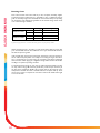
1
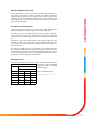
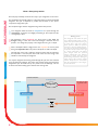
Ecodan® Air Source Heat Pump
Home Owner Guide
PUHZ-W50VHA-BS
PUHZ-W85VHA-BS
PUHZ-HW140VHA-BS / YHA-BS
1
Contents
INTRODUCTION
•
Heat Pump Overview
•
Co-efficient of performance
•
Varying Factors
•
How a heat pump works
•
Room thermostat
•
Controller PAR-W21MAA
•
Hot Water / Space Heating
•
Selecting cylinder thermostat
•
Weather Compensation
3
3
3
4
5
5
5
5
5
•
COMPONENT PARTS
Key Parts
6
•
•
•
SPECIFICATION
PUHZ-W50VHA-BS
PUHZ-W85VHA-BS
PUHZ-HW140VHA-BS / YHA-BS
7
8
9
CONTROLLER SET-UP
Display and Operation
Change Language
Setting Day and Time
Heating Set-up
10
11
11
12
•
•
•
•
•
•
•
•
•
•
•
Recommended Settings
Radiators
Hot water Set-up
Available Modes
How to lock/unlock buttons
Error codes indication
Displays
13
13
13
14
15
15
16
•
•
•
OPERATING CONDITIONS
Flow Rates
Start Up
Control Strategy
17
17
17
•
RUNNING COSTS
Running Costs
18
•
•
•
•
ADDITIONAL INFORMATION
Time Clock Set-Up/ Patterns
Domestic Hot Water Immersion Heater
Legionnaires Disease
FAQ’s
19
20
20
20
TROUBLESHOOTING
Troubleshooting
Maintenance
21
21
•
•
Abbreviations / Glossary of terms
Ambient Temperature
Anti freeze mode
ASHP
COP
∆T / Delta
Flow Rate
Flow Temperature
FTC
Heating Eco mode
Heating Mode
Hot water mode
Immersion Heater
Refrigerant
UFH
Weather compensation
2
The outdoor temperature
Heating to prevent water pipe from freezing
Air source heat-pump boiler
Coefficient of performance, see page 3 for full explanation
Change in temperature between two variables
The speed the water travels within the circuit that is heated by the Ecodan® unit
The temperature of the water within the circuit that is heated by the Ecodan® unit
Flow Temperature Controller, see page 6 for full explanation
Similar to ’heating mode’ with weather compensation
For heating space either through radiators or under floor heating
Heating of the tank to provide hotwater
Booster heater to raise temperatures, see page 21 for use with Ecodan® unit
A compound used within a heat cycle that goes through a phase change during this cycle
changing from gas to liquid and back again
Under Floor Heating
Flow temperatures change dependent on outdoor conditions, see page 5 for full explanation
Heat Pump Boiler Overview
INTRODUCTION
A heat pump works in a similar way to that of a domestic fridge, although in reverse. Heat is moved from one source to another. The outdoor based Ecodan
exploits the physical properties of a refrigerant to heat water that flows into the
dwelling to the radiators/ under-floor heating and the hot water cylinder for hot
water usage. This is a very efficient way to heat water compared to conventional
gas, oil and solid fuel boilers.
Co-efficient of Performance
Sometimes referred to as COP, it is the amount of heat energy provided by the
heat pump, divided by the electrical energy consumed by the heat pump.
The efficiency of a heat pump boiler is high compared to a gas boiler. Typically for
every 1kW of input energy, 3kW of outputted heat energy can be achieved, that
creates a COP of 3.0. If heat energy increases for the same input the COP would
rise.
Compared to a gas fired conventional boiler, 1kW of input energy provides less
than 1kW of output energy or heat. A heat pump boiler utilises heat energy from
the outside air even at low temperatures to provide either central heating or hot
water for the house.
The COP for an ASHP will vary as it is dependent on the outside temperatures
and the desired temperature of hot water/ space heating. The smaller the difference between these figures the more efficient the Ecodan® will become. When it
is cold outside power input increases as the Ecodan® works harder to extract
heat from the air, thus COP drops in cold conditions.
Varying Factors
The table below shows how performance will vary. The Inlet/ Outlet temperature
represents the water temperature
COP at varying factors
progressing through the Ecodan®
°C ambient
Water temp °C
unit and heating up.
Inlet / Outlet
30 / 35
40 / 45
50 / 55
-15
1.77
1.41
1.37*
-7
2.41
1.89
1.46
2
2.97
2.27
1.81
7
3.96
3.05
2.28
20
5.39
3.90
2.87
Figures for 8.5kW heat pump
* Ambient Temperature –10°C
3
How a heat pump works
The heat pump essentially works the same way as your refrigerator but in reverse.
Step 1
The first phase begins with the refrigerant being cold and low pressure.
The refrigerant within the circuit is compressed as it passes through the
compressor. It becomes a hot highly pressurized gas. The temperature also
rises typically to 60°C
Step 2
The refrigerant is then condensed as it passes across a plate heat exchanger. Having a cooler side to the heat exchanger it decreases the temperature, so it changes the property of the refrigerant from a gas to a liquid.
Step 3
Boiling points:
Now a cold liquid it still has a high pressure. For expansion to occur it passes
through an expansion valve. The pressure drops but it is still a cold liquid.
Step 4
INTRODUCTION
The Ecodan® is hermetically sealed (no refrigeration piping involved) with R410A
refrigerant, the cycle it completes to produce heat is known as the vapourcompression refrigeration cycle:
The final stage of the cycle is when the refrigerant passes into the evaporator
and evaporates. It is at this point when some of the free heat energy in the
outside air is absorbed by the refrigerant.
It is only the refrigerant that is being passed through this cycle; the water is heated
up by the plate heat exchanger. The cooler water extracts energy from the hotter
refrigeration cycle, the water heats up as it passes across the exchanger. This water flows towards the heating system and hot water storage tank.
The refrigerant used within the cycle
has a different boiling point to water,
which boils (turns from liquid to gas)
at 100°C. This is only true at atmospheric pressure. When the pressure
increases so does the boiling temperature; decrease the pressure and boiling
temperature drops. Liquid turns to gas
at a lower temperature. The boiling
point changes when the pressure
changes. Refrigerants have different
properties to water and have much
lower boiling temperatures. During the
fourth stage of the cycle the outside
ambient temperature is much hotter
than the temperature of the refrigerant and will heat it.
Sealed Ecodan® Unit
1 compressed
Outside Air
compressor
4 evaporates
2 condensed
Evaporator
Heat Exchanger
Expansion
3 expansion
4
Hot water for heating and hot water
Room Thermostat
INTRODUCTION
The aim of the thermostat is to control the room temperature, although one model used will vary from
one home to another its function will not. This is the homeowner’s connection to the heat pump boiler.
The room thermostat and the time clock (both supplied by 3rd party manufacturers.) are the 2 main controls for the home owner to use.
Controller PAR-W21MAA
This controller is supplied with the Ecodan® heat pump. Its primary function is as a commissioning tool to
set the target flow temperature. It has a display to show the actual flow temperature and the target temperature. The set-up, displays and modes available are explained later in the manual. Once installed there
are factory settings that will allow the heat pump boiler to start operating immediately, optimising these
temperatures to suit your home will improve running conditions and lower your energy consumption.
These temperatures should be selected during the commissioning stage.
Hot water / space heating
Space heating and hot water heat up cannot be performed at the same time. Hot water will always take
priority over space heating should there be a demand for both; once the tank is heated and up to temperature the unit will change over to the heating of the property. This setting cannot be changed.
Due to lower flow temperature provided by a heat pump boiler additional care must be taken when sizing
the radiators. Ensure that the total heating demand of the property is met by the correct size of heat
pump.
Selecting cylinder thermostats
Care should be taken when selecting a cylinder thermostat. If the thermostat is set higher than the achievable storage temperature of 55°C then space heating will be held off due to hot water priority. It is recommended that a thermostat on which the maximum temperature can be locked is used. This will prevent
the stat asking for a temperature that cannot be achieved thus preventing space heating from occurring.
(See page 18 for typical heat up times for the hot water tank).
Weather Compensation
The Ecodan® system has a weather compensation mode. This feature is called Eco-heating. This mode
offers varying flow temperatures to the radiators depending on the outside temperature. These temperatures are selected and set by the installer when commissioning the Ecodan® system for further details see
the controller set-up. It is recommended that Eco-heating mode is used for central heating.
5
Component Parts
COMPONENT PARTS
Main Home Owner Controls
The installed Ecodan® will include
several key parts. Some of their functions will require human input to control the effect of the unit,
Room Thermostat:
Used by homeowner to set the required temperature of the household
Two Channel Timer Clock:
Used by homeowner to set
on/off running periods
Pump:
This moves the flow of heated
water from the Ecodan® to the
heating system and hot water tank.
Hot water tank:
Within this tank the
water is heated via a
coil positioned inside,
the heated water leaves
the top of the tank for
showers, baths and
taps.
Controls, pumps and other components supplied and packaged
together
Mitsubishi Supplied Parts
PAR-W21MAA:
Controller used
to activate settings on Ecodan®.
These settings are
explained in later
pages.
Flow Temperature Controller::
Within this box is the brains behind the system that allows the
Ecodan® to speak to the boiler
6
PUHZ-W50VHA-BS
Dimensions (mm)
PUHZ-W50VHA-BS
Width
950
Depth
330+30*
Height
740
Weight (kg)
64
Airflow (m3/min)
50
Nominal sound level (dBA)
45 ◊
Low noise mode (dBA) @ 7°C
Guaranteed operating range
40
(Outdoor)
Electrical Supply
Single
Running current (A) [Max]
5.4 [13]
Fuse Rating (A)
Heating A7/W35
Primary Flow Rate
- 15 ~ +35°C
220-240v, 50Hz
Phase
Heating A2/W35
SPECIFICATION
Specifications
16
Capacity (kW)
5.0
COP
3.13
Power Input (kW)
1.6
Nominal Flow Rate (L/min)
14.3
Capacity (kW)
5.0
COP
4.1
Power Input (kW)
1.22
Nominal Flow Rate (L/min)
14.3
Maximum (L/min)
25.8
Minimum (L/min)
10
Nominal Conditions
A2 / W35
A7 / W35
Outside air temperature (dry)
2°C
7°C
Outside air temperature (humid)
1°C
6°C
Water temperature (inlet/outlet)
30 / 35°C
30 / 35°C
* Grille
◊ At distance of 1m from the outdoor unit
7
PUHZ-W85VHA-BS
SPECIFICATION
Specifications
Dimensions (mm)
PUHZ-W85VHA-BS
Width
950
Depth
330+30*
Height
943
Weight (kg)
77
Airflow (m3/min)
55
Nominal sound level (dBA)
48 ◊
Low noise mode (dBA) @ 7°C
Guaranteed operating range
42
(Outdoor)
- 20 ~ +35°C
Electrical Supply
220-240v, 50Hz
Phase
Single
Running current (A) [Max]
10.3 [23]
Fuse Rating (A)
Heating A2/W35
Heating A7/W35
Primary Flow Rate
Nominal Conditions
Capacity (kW)
8.5
COP
2.95
Power Input (kW)
2.88
Nominal Flow Rate (L/min)
25.8
Capacity (kW)
9.0
COP
3.85
Power Input (kW)
2.34
Nominal Flow Rate (L/min)
25.8
Maximum (L/min)
25.8
Minimum (L/min)
10
A2 / W35
A7 / W35
Outside air temperature (dry)
2°C
7°C
Outside air temperature (humid)
1°C
6°C
Water temperature (inlet/outlet)
30 / 35°C
30 / 35°C
* Grille
◊ At distance of 1m from the outdoor unit
8
25
PUHZ-HW140VHA-BS / YHA-BS
Dimensions (mm)
PUHZ-HW140VHA-BS/ YHA-BS
Width
1020
Depth
330+30*
Height
1350
Weight (kg)
134 / 148
Airflow (m3/min)
100
Nominal sound level (dBA)
53 ◊
Low noise mode (dBA) @ 7°C
Guaranteed operating range
46
(Outdoor)
Electrical Supply
Single / 3 Phase
Running current (A) [Max]
14.9 [35] / 5.1 [13]
Fuse Rating (A)
Heating A7/W35
Primary Flow Rate
- 25 ~ +35°C
220-240v, 50Hz /
380-415v, 50Hz
Phase
Heating A2/W35
SPECIFICATION
Specifications
40 / 16
Capacity (kW)
14
COP
2.69
Power Input (kW)
5.21
Nominal Flow Rate (L/min)
40.1
Capacity (kW)
14.0
COP
4.19
Power Input (kW)
3.34
Nominal Flow Rate (L/min)
40.1
Maximum (L/min)
40.1
Minimum (L/min)
20.0
Nominal Conditions
A2 / W35
A7 / W35
Outside air temperature (dry)
2°C
7°C
Outside air temperature (humid)
1°C
6°C
Water temperature (inlet/outlet)
30 / 35°C
30 / 35°C
* Grille
◊ At distance of 1m from the outdoor unit
9
CONTROLLER SET-UP
PAR-W21MAA
The PAR-W21 controller is used to optimise the running of the system. Listed below are all the available buttons and displays on the
LCD screen. The following pages explain the setting up of the functions needed to operate the Ecodan®
1 Day of the Week
Shows the current day of the week
2 Identifies the current operation
Shows the operating mode, etc.
* Multi language display is supported.
Time/Timer Display
Shows the current time, unless the simple
or Auto Off timer is set.
If the simple or Auto Off timer is set,
shows the time remaining.
8 “Locked” indicator
Indicates that remote controller buttons
have been locked.
7 ON/OFF indicator
Indicates if the time is set ON/OFF
9 Timer indicators
The indicator comes on if the corresponding timer is set.
10 Error indicator
Comes on when error occurs.
5 “Centrally Centralised” indicator
Indicates that operation of the remote
controller has been prohibited by a master
controller.
4 Temperature indicator
Shows the current water temperature
11 Power On indicator
Indicates that the power is on.
6 “Timer is Off” indicator
Indicates that the timer is off.
For purposes of this explanation, all parts of the display are shown. During the actual
operation, only the relevant items will be displayed.
3 Temperature Setting
Shows the target temperature
F Set Temperature buttons
I ON/OFF button
H Setting change button
G Timer Menu button
(Monitor/ Set button)
E Mode buttons (Return button)
A CIR.WATER button
( <Enter> button)
C Set Time button
D Timer On/Off
button
B not available
Test run function is not available with this FTC unit
J Self check (clear) button
This icon is shown when there is no demand for either hotwater or central heating. On the display section it is
represented by 5. No flow temperatures will be displayed on the screen.
10
CONTROLLER SET-UP
Change Language
The initial language setting is English. If you require to change this follow the 4 steps below. The instructions in this guide
use English for the annotated displays, whatever language is selected the combination of buttons will not alter.
1
Step 1:
Hold down buttons D and E for 2 seconds.
This activates the controller
Normal Display
DE
2
Step 2:
Press button G. To scroll through the languages
Change Language
G
3
Language G
Language G
English (GB)
Deutsch (D)
Language G
Espanol(E)
G
G
Language
Spräk VAL
4
Language
Pycck(RU)
G
Language
French(F)
G
Language
Italiano(I)
DE
Step 3:
For each press of button G will move
through the 7 available languages. Leave on
desired language to proceed.
Step 4:
Hold down buttons D and E for 2 seconds.
To return to original screen.
Normal Display
Setting day of the week and time
Unlike having a default language, the day and time will run from the day the system is switched on. To change these settings
please following instructions.
1
Step 1:
Press either of the C buttons
to start
Normal Display
C
2
Mon
3
Time
Tue
Wed
Thu
Fri
Sat
Step 3:
Press either of the C buttons
as necessary to set the time.
Sun
Step 2:
Press button D to advance
through each day. Once on
current day press C to set
time.
To finish:
Press button E when settings
are complete.
As you hold the C button down, the time (displayed at 1) will increment first in one minute intervals, then in ten minute
intervals, and then in one hour intervals. This works in either direction.
Note:
“PLEASE WAIT” message
This message is displayed for approximately 3 minutes when power is supplied to the FTC unit or when the unit is recovering from a power failure
“NOT AVAILABLE” message
This message is displayed if a button is pressed to operate a function that the FTC unit does not have, or a function that is
not available due to the setting.
Throughout this guide the buttons on the controller are referenced by letters and displays by numbers ; this key can be found on page 10
11
CONTROLLER SET-UP
Heating Set-up (Heating Eco Mode)
Whilst heating a property the ‘eco heating’ is the recommended mode to use; this setting is a heating function with weather compensation. This function sets the target temperature depending on the outdoor temperature. The buttons on the controller are
represented by letters explained on page 10.
What is on the screen
Flashing Temp. represents
Keypad selection
Notes
1. Normal mode
Hold down H for This activates the controller, the display will flash
3 seconds
with the words ‘loading’
2. Water Temp Heating
Press E
This mode is not necessary and should be skipped
3. Water Temp Eco Heating No.1
Low Ambient Target Flow
Press F
Move up or down to desired temperature. Low
ambient flow/ temperature is denoted by No.1
4. Water Temp Eco Heating No.1
Low Ambient Target Flow
Press D
Changes to next temperature variable
5. Water Temp Eco Heating No.1
Low Ambient Outdoor Temperature
Press F
Move up or down to desired temperature
6. Water Temp Eco Heating No.1
Low Ambient Outdoor Temperature
Press E
Changes to next temperature variable
7. Water Temp Eco Heating No.2
High Ambient Target Flow
Press F
Move up or down to desired temperature. High
ambient flow/ temperature is denoted by No.2
8. Water Temp Eco Heating No.2
High Ambient Target Flow
Press D
Changes to next temperature variable
9. Water Temp Eco Heating No.2
High Ambient Outdoor Temperature
Press F
Move up or down to desire temperature
10. Water Temp Eco Heating No.2 High Ambient Outdoor Temperature
Press A
This must be pressed to memorise these settings.
The screen will flash ’settings’ for several seconds
11. Water Temp Eco Heating No.2 High Ambient Outdoor Temperature
Hold down E
This will end the parameters that need to be set.
Pressing D will return to step 3.
When setting up the controller, pressing button A must be used to memorise these settings.
Once the ‘heating eco’ mode is activated the parameters need to be chosen. The recommended temperatures are listed
on page 19.
Throughout this guide the buttons on the controller are referenced by letters and displays by numbers ; this key can be found on page 10
When setting up the controller, pressing button A must be used to
memorize the settings.
Once these have been set-up, likewise with the heating a temperature
needs to be set-up, these instructions are on the following page.
FLOW TEMP.
A
No.1
Heating Parameters
The weather compensation feature allows for higher temperatures to
be achieved when the outdoor temperature is warmer.
B
No.2
OUTDOOR
TEMP.
No. 1
12
No.2
CONTROLLER SET-UP
Recommended Settings
The controller has settings pre-installed that will provide adequate hot water and heating, but they can be amended using
the instructions in the first two sections. The temperatures that should be used are as follows
PAR-W21MAA recommended flow temperatures
Factory Settings
Recommended
50°C
58°C
Hot Water
Eco Heating
Low Ambient Temperature
Under-floor
-2°C ~ 40°C
-10°C ~ 38°C
Radiator
High Ambient Temperature
Under-floor
-2°C ~ 45°C
15°C ~ 30°C
17°C ~ 25°C
Radiator
15°C ~ 30°C
Lower flow temperatures lead to greater efficiencies.
Radiators
Please note that heat pumps provide lower flow temperatures to radiators than a conventional gas boiler. Rather the
radiators turning on/off locally as with a gas boiler, heat pumps provide a more consistent lower flow temperature which
allows for more efficiency and greater comfort.
Hot Water Set-up
The recommended temperatures (as stated above) need to be programmed into the controller
What is on the screen
Flashing Temp. represents
Keypad selection
Notes
1. Normal mode
Hold down H
for 3 seconds
This activates the controller, the display will flash
with the words ‘loading’
2. Water Temp Heating
Press E
This mode is not necessary and should be skipped
3. Water Temp Heating Eco No.1
Press E
This mode is not necessary and should be skipped
4. Water Temp Heating Eco No.2
Press E
This mode is not necessary and should be skipped
5. Water Temp Hot Water
Water Temp Hot Water
Press D
Move up or down to desired temperature
6. Water Temp Hot Water
Water Temp Hot Water
Press A
Once pressed it will memorise these settings. The
screen will flash ‘settings’ for several seconds.
7. Water Temp Hot Water
Water Temp Hot Water
Hold down H
This will end the parameters that need to be set.
Pressing button I (ON/OFF) will also end the set-up.
Throughout this guide the buttons on the controller are referenced by letters and displays by numbers ; this key can be found on page 10
13
CONTROLLER SET-UP
Available Modes
There is a selection of modes on the controller that the end user can choose for set-up purposes; please note that some of these
may have been removed or disabled for use with the Ecodan® unit.
From the normal display it will always skip progress to ‘water temp heating’, each press of button E will skip to the next available
mode. When setting up the controller, pressing button A must be used to memorize the settings.
1
Step 2:
The first option will be ‘water temp heating’.
Each time button E is pressed it will move to the
next available mode.
Step 1:
From the regular display holding button H will
activate the controller. The display will flash
with the words ‘loading’
Normal
Display
H
2
E
Water Temp
Ant-Freeze
E
Water Temp
Ant-Freeze
E
Water Temp
Heating
E
Water Temp
Eco Heating
No.1
E
Water Temp
Eco Heating
No.2
Water Temp
Hot Water
E
Water Temp
Ant-Freeze
E
Water Temp
Ant-Freeze
F
F
F
E
3
F
E
Desired
Temperature
4
E
Note:
These options can
be disregarded.
They might have
been removed or
disabled.
E
Desired
Temperature *
A
Desired
Temperature *
H
‘Settings’
Normal
Display
E
Desired
Temperature
Step 3:
The up and down F buttons can be used to
select the desired temperature. Pressing button
E will move to next available mode. Temperatures changes of that mode can then be made.
Step 4:
From any of the modes in step 3, pressing button A will memorise these settings. The screen
will flash ‘settings’ for several settings. Holding
down button H will end the set-up.
* There are two temperatures that need to be set, the target and outdoor temperatures. The up and down F buttons can
be used to select the desired temperature. Button D will alternate between the two variables.
Throughout this guide the buttons on the controller are referenced by letters and displays by numbers ; this key can be found on page 10
14
CONTROLLER SET-UP
How to lock the Buttons
While holding down the button A, press and hold down the button I for 2 seconds. The “Locked” indication appears on the screen (display 8), indicating that
the lock is now engaged.
* If locking has been disabled in Function Selection of remote controller, the
screen will display the “Not Available” message when you press the buttons as
described above.
If you press a locked button, the “Locked” indication (display 8) will blink on the
display
How to Unlock the Buttons
1. While holding down the button A press and hold down the button I for 2 seconds—so that the “Locked” indication disappears from the screen (display 8)
Error Codes Indication
If the ON lamp and display 10 are
both blinking: This means that the
Ecodan® ASHP is out of order and
operation has been stopped (and
cannot resume). Take note of the
indicated unit number and error
code, then switch off the power to
the Ecodan® ASHP and call your
installer.
If you have entered contact
number to be called in the event of
a problem, the screen displays this
number.
(You can set this up under
Function Selection of remote
controller. For information, refer
to table below).
Alternating Display
When the Check Button is pressed:
If only the display 10 is blinking (while the ON lamp remains lit): Operation is
continuing, but there may be a problem with the system. In this case, you should
note down the error code and then call your installer for advice.
If you have entered contact number to be called in the event of a problem, push
the button J to display it on the screen.
15
CONTROLLER SET-UP
Display
The PAR-W21MAAhas many different functions that control the performance of
the Ecodan®. Below are the symbols and displays used for each function.
Waiting for start-up
Operational Mode
Water temperature display
Heating
Function selection
Heating ECO
Operation function limit setting
Hot water
Mode Skip setting
Anti-freeze
Mode skip
Heating
Stand by (Hot adjust)
Heating ECO
Defrost
Hot water
Not in use button
Anti-freeze
Check (Error)
Cooling
Test run
Temperature range limit setting
Self check
Temperature
range limit setting
mode
Change language
Language selection
Hot water
Anti-freeze
Cooling
Display change
Mode selection
Temperature display °C/°F setting
Use of clock setting
Setting the day of the week and time
Loading
Installation
Once installed by a fully trained engineer the system will be ready to use as day,
time and target flow temperatures will be set.
The end user should be aware of how to change:
The day and time
Target flow temperature (for all modes)
Ecoheating parameters
Please note the temperature given are for guidance only. The flow temperatures
required will vary on the construction of the radiators or under-floor heating
system as well as the heat load of the room/house. The installer should set-up
your system to these temperatures but they can be altered later on if required.
Fine tuning of the operating conditions of the Ecodan can reduce your energy
bills, dropping just the flow temperature 1°C can make a difference to the bill.
16
OPERATING CONDITIONS
Flow Rates
To achieve good system efficiencies higher flow rates are recommended on the
radiator/ under-floor circuit.
Ecodan required system flow rates
Ecodan® Model
Minimum
Maximum
Flow Rate (l/m)
Flow Rate (l/m)
PUHZ-W50VHA-BS
6.5
14.3
PUHZ-W85VHA-BS
10
25.8
PUHZ-W140VHA-BS
20
40
Hot water cylinder heat-up times
Hot water heat up times vary depending on the size of the tank. Typically it will
take about one hour to recover a 150 litre storage tank from cold. This heat up
time is dependent on the size of the hotwater cylinder and the size of the heat
pump connected to it. When heating up the hot water cylinder, try to do so during off peak hours. By selecting an appropriate electricity supply offering off peak
economy tariffs. It is recommended to have either one or two hot water heat up
cycles per day, though this is dependent on usage patterns.
These figures are not exact as the starting temperature of the tank as well as the
ambient temperature can vary. They should be treated as guidelines. It should also
be remembered that during winter the mains water entering the house will be
colder and require slightly longer to heat up to the required temperature.
These figures are based on the 8.5kW unit. The heat up times are based on cold
water from the mains heated to 55°C.
Tank Size
(litres)
Heat up times
(minutes)
150
52
180
62
210
73
Control Strategy
An inverter driven air source heat pump delivers heat in a different manner to a
traditional fossil fuelled heating system. A gas or oil fired system will produce
water at higher flow temperatures and have a large excess capacity in order to
heat the property up relatively quickly. An air source heat pump works most
efficiently when it is producing lower flow temperatures (for space heating between 35oC and 50oC depending on the type of emitter i.e. radiators or underfloor heating).
Due to the low flow temperatures it is necessary and more efficient for the heat
pump to be running constantly when heating is required, this not only maintains a
more consistent indoor temperature but also means that the heat pump will use
considerably less electrical input due to the lower flow temperatures. It is possible to run the Ecodan like a traditional boiler using a timed control strategy, this
will however result in fluctuating internal temperatures and a higher overall
power consumption meaning increased running costs.
17
Running Costs
RUNNING COSTS
Due to the fact that most houses will vary in size, occupants, electricity supplier
and desired heating requirements it is impossible to give a completely accurate
guide to electricity usage with a Ecodan® Air Source Heat Pump, but providing
the homeowner has followed the guidelines in this manual savings will be made
over conventional gas/ oil boilers.
Carbon (kg) Actual Running Cost (£)
4 Bedroom House
3 Bedroom House
Ecodan ®
2405
443
Oil Burner
5129
730
Ecodan ®
2055
380
Oil Burner
4384
624
Typical usage patterns—oil and electricity prices as per January 2008
When transferring from a gas boiler to a heat pump boiler please be aware that
your electrical bills will rise. The additional cost to your electrical bill should be
less than the previous gas bill.
If this is higher than previous, the homeowner will need to review the settings on
the air source heat-pump boiler as it is likely to be running for longer than necessary. It is important to not waste energy as unnecessary CO2 will be emitted and
the homeowner will be paying for it. Significant savings will be made if the ASHP is
working in an optimum operating condition.
To find the cheapest energy for your area try online with www.uswitch.com they
can help reduce energy bills. Economy tariffs that provide cheaper electricity in
the early hours compliment ASHP’s; the hot water tank can be heated up at the
cheapest time and then hot water is available when the occupants wake up. These
can be set by a timer so occupants do not need to wake in the middle of the night
to turn on the tank.
18
ADDITIONAL INFO.
Time clock pattern set-up
The Flow Temperature Controller time clock patterns must be set to accommodate a hot water priority system. For example: The hot water heat up cycle
should have an ON/OFF time approximately 1.5 hours apart (dependent on the
cylinder capacity), this time should be outside the time period where space heating is required as it will not be available while hot water is taking place. Hot water
heating should be set to occur during the night periods where space heating is
not required and cheap electricity tariffs are available.
Time clock patterns
The Ecodan® system incorporates hot water demand priority this means that if
there is a demand for both modes hot water will always occur before space heating.
Due to this the periods at which hot water and space heating are programmed to
operate are extremely important. The hot water heat up times should be programmed to occur during periods when space heating is not required, this is usually the early hours of the morning and early afternoon. Using the hot water recovery time period taken during the commissioning stage ON/OFF time must be
programmed by the commissioning engineer into the 2 channel timeclock, for
example if the cylinder took 60 minutes to reach 55°C then the hotwater ON
time should be for example 3.00am and the OFF should be 4.15am leaving 15
minutes additional buffer. After this time space heating will be allowed to operate
as required.
Important Note- If the hot water demand is left ON continuous operation rather
than being timeclocked to switch OFF then the homeowner may experience unnecessary high running costs.
Economical Time Clock Patterns & Flow Temperatures
To gain the full benefits from the Ecodan® system the target flow temperatures
and timeclock patterns need to be configured to suit the actual property demands. The most economical way of operating the system is to have it running at
the lowest flow temperature possible to suit the properties thermal losses.
To do this the heating demand from the time clock should be left constantly operational and the flow temperatures should be reduced to a point where the
property is maintained at the design temperature (usually 21°C) without being
switched ON and OFF from the room thermostat or TRV’s. 7-day timer clocks
with night set-back can also offer good system efficiencies.
Important note- If the heating demand is left on continuous operation and the
target flow temperatures are not reduced to their lowest possible then the
homeowner may experience unnecessarily high running costs.
Example timeclock patterns
Below is an example of a standard timeclock pattern please note this is for reference only as the inputted times should suit the site environment and the homeowner preferences.
Heating mode – continuous operation with reduced flow temperatures.
Hotwater mode :
3.00am ON
4.45am OFF
2.00pm ON
3.45pm OFF
19
Domestic Hot Water Immersion Heater
ADDITOINAL INFO.
As the Ecodan® ASHP can heat domestic hot water cylinder to 55°C. Pasteurization should be carried out by an
immersion heater situated in the body of the hot water cylinder. The heater should be timed to operate after
the Ecodan has completed a hot water cycle thus completing the lowest temperate rise possible (from 55°C to
60°C). Please note the larger the temperature rise completed by the immersion heater the less efficient the system becomes.
Immersion Heater (boosting from 55°C—60°C
To determine the ON time of the immersion heater the
Tank Size
Heat up times
recovery period taken during the commissioning stage
(litres)
(minutes)
should be used. The ON time from the immersion heater
should be the ON time of the Ecodan® hotwater heating +
150
18
the recovery period taken during the commissioning stage.
180
21
This heat up times have been based upon using a 3kW
210
25
Immersion heater.
Legionnaire’s Disease
The immersion heater should be time clocked to take the cylinder up to 60°C shortly after the heat pump has
heated the cylinder up to 55°C set out in the current building regulations concerning control of Legionella bacteria. Immersion heater cylinder pasteurization (60°C) should be controlled in accordance with BS6700.
FAQ’s
Q) Why is the exhaust air from the outdoor unit cold?
A) The heat pump boiler is working in reverse to a refrigerator therefore has removed the heat in the air and
put it onto the water.
Q) How long will the defrost cycle last for?
A) A complete cycle will take less than 3 minutes.
Q) How often do I need to clean the outdoor unit?
A) Visual checks should be carried out every 6 months and also an annual service by an approved Ecodan installer.
Q) My electricity bill is too high, how can reduce this?
A) Well insulated houses have lower heating loads, also reducing the flow temperatures through the PARW21MAA controller. Always ensure Eco mode is selected for central heating. Eco-mode flow temperatures
should be set as commission stage and suit the property type. Lower flow temperatures lead to lower operating
costs.
Q) How does Ecodan help reduce carbon emissions?
A) Because Ecodan®'s output efficiencies are in the seasonal order of 3 to 3.5 (i.e. 300% to 350%), the actual
amount of electrical energy consumed from the national grid is dramatically reduced. So even taking in to account the reduced CO2/kWh for gas (0.19) against CO2/kWh for electricity (0.43) Ecodan emits far less CO2
than even the highest efficiency condensing gas boiler.
Q) Are air source heat pumps classed as a renewable technology?
A) Within the Climate Change and Sustainable Energy Act (Sources of Energy and Technologies), yes. Here air
source heat pumps are defined as a microgeneration technology. However, there is still debate as to whether air
source heat pumps can be truly classed as a renewable technology if the primary power (the electricity) does not
come from a renewable source.
20
TROUBLESHOOTING
Basic Troubleshooting
Below is a list of basic problems and actions.
For a full list of Ecodan® fault codes, synopsis and remedial actions please consult the relevant service manual available to
download from www.mitsubishielectric.co.uk/heating
Water does not heat well
• Check the temperature adjustment and adjust the set temperature.
• Make sure that there is plenty of space around the outdoor
unit.
Water or vapour is emitted from the outdoor unit
• During the heating mode, water may form and drip from the
heat exchanger of outdoor unit
• During the defrosting mode, water on the heat exchanger of
outdoor unit—evaporates and water vapour may be emitted.
The operation indicator does not appear in the
remote controller display
appears in the remote controller display.
• Turn on the power switch.
Will appear in the remote
controller display.
• This is the normal display, the system is waiting for a signal
to operate from the control equipment
When restarting the outdoor unit soon after stopping it, it does not operate even though there is a
demand from the control equipment.
• Wait approximately 3 minutes. (Operation has stopped to
“PLEASE WAIT” appears in the remote controller
display.
• The initial settings are being performed. Wait approximately
protect the outdoor unit.)
3 minutes.
• If the remote controller is not only for FTC, change it
An error code appears in the remote controller
display
• The protection devices have operated to protect the FTC
and outdoor unit
• Consult the error code section of the relevant service manual or call the technical support helpline on 0870 3000 300
for assistance
Maintenance
The maintenance is low on Ecodan® due to the unit being a sealed system like a fridge. Visual
checks that can be carried out by the homeowner keeping debris like leaves clear of the unit. Also
check for signs of damage to the unit. Repairs should not be carried out by the homeowner, this
will invalidate the warranty issued.
21
If you have any further queries please contact your installer
22