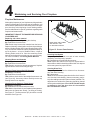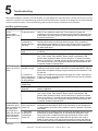
1
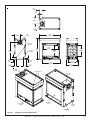
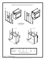
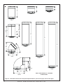
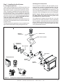
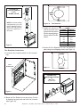
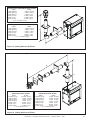
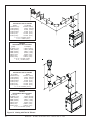
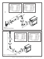
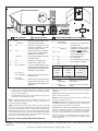
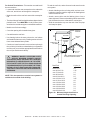
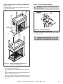
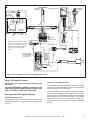
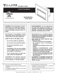
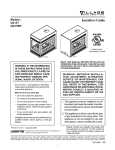
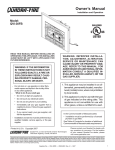
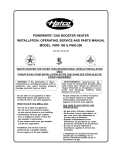
Owner’s Manual
Installation and Operation
Models:
QV-Pier
QV-ST
Series: HV-IPI
CAUTION
DO NOT DISCARD THIS MANUAL
operating
and maintenance
instructions included.
• Read,
understand and follow
these instructions for safe
installation and operation.
WARNING: If the information in these
instructions is not followed exactly, a fire
or explosion may result causing property damage, personal injury, or death.
• Do not store or use gasoline or other flammable vapors and liquids in the vicinity of this
or any other appliance.
• What to do if you smell gas
- Do not try to light any appliance
- Do not touch any electrical switch. Do not
use any phone in your building.
- Immediately call your gas supplier from a
neighbor’s phone. Follow the gas supplier’s instructions.
- If you cannot reach your gas supplier, call
the fire department.
• Installation and service must be performed by
a qualified installer, service agency, or the gas
supplier.
Printed in U.S.A.
Copyright 2006
Quadra-Fire, a brand of Hearth & Home Technologies Inc.
1445 North Highway, Colville, WA 99114
• Leave
this manual with
party responsible for
use and operation.
WARNING: IMPROPER INSTALLATION,
ADJUSTMENT, ALTERATION, SERVICE OR
MAINTENANCE CAN CAUSE INJURY OR
PROPERTY DAMAGE. REFER TO THIS
MANUAL. FOR ASSISTANCE OR ADDITIONAL INFORMATION CONSULT A QUALIFIED
INSTALLER, SERVICE AGENCY, OR THE
GAS SUPPLIER.
This appliance may be installed in an aftermarket,
permanently located, manufactured (mobile) home,
where not prohibited by local codes.
This appliance is only for use with the type of gas
indicated on the rating plate. This appliance is not
convertible for use with other gases, unless a certified kit is used.
Î
• Important
D
DI O N
SC OT
AR
D
In the Commonwealth of Massachusetts:
• installation must be performed by a licensed plumber
or gas fitter;
• a CO detector shall be installed in the room where the
appliance is installed.
Please contact your Quadra-Fire dealer with any questions
or concerns. For the number of your nearest Quadra-Fire dealer,
please call 1-800-926-4356.
This product may be covered by one or more of the following patents: (United States) 4593510, 4686807, 4766876, 4793322, 4811534, 5000162, 5016609, 5076254, 5113843, 5191877, 5218953, 5263471, 5328356,
5341794, 5347983, 5429495, 5452708, 5542407, 5601073, 5613487, 5647340, 5688568, 5762062, 5775408, 5890485, 5931661, 5941237, 5947112, 5996575, 6006743, 6019099, 6048195, 6053165, 6145502, 6170481,
6237588, 6296474, 6374822, 6413079, 6439226, 6484712, 6543698, 6550687, 6601579, 6672860, 6688302B2, 6715724B2, 6729551, 6736133, 6748940, 6748942, 6769426, 6774802, 6796302, 6840261, 6848441,
6863064, 6866205, 6869278, 6875012, 6880275, 6908039, 6919884, D320652, D445174, D462436; (Canada) 1297749, 2195264, 2225408, 2313972; (Australia) 780250, 780403, 1418504 or other U.S. and foreign
patents pending.
Quadra-Fire • QV-PIER, QV-ST Series: HV-IPI • 2005-901 Rev. G • 2/06
1
Safety and Warning Information
!
!
!
!
!
!
!
!
!
2
READ and UNDERSTAND all instructions carefully
before starting the installation. FAILURE TO
FOLLOW these installation instructions may result
in a possible fire hazard and will void the warranty.
Prior to the first firing of the fireplace, READ the
Using Your Fireplace section of the Owners Guide.
DO NOT USE this appliance if any part has been
under water. Immediately CALL a qualified service
technician to inspect the unit and to replace any part
of the control system and any gas control which has
been under water.
!
!
!
THIS UNIT IS NOT FOR USE WITH SOLID FUEL.
These units MUST use one of the vent systems
described in the Installing the Fireplace section of
the Installers Guide. NO OTHER vent systems or
components MAY BE USED.
This gas fireplace and vent assembly MUST be
vented directly to the outside and MUST NEVER be
attached to a chimney serving a separate solid fuel
burning appliance. Each gas appliance MUST USE
a separate vent system. Common vent systems are
PROHIBITED.
INSPECT the external vent cap on a regular basis to
make sure that no debris is interfering with the air
flow.
The glass door assembly MUST be in place and
sealed, and the trim door assembly MUST be in
place on the fireplace before the unit can be placed
into safe operation.
Installation and repair should be PERFORMED by a
qualified service person. The appliance and venting
system should be INSPECTED before initial use
and at least annually by a professional service
person. More frequent cleaning may be required
due to excessive lint from carpeting, bedding
material, etc. It is IMPERATIVE that the unit’s
control compartment, burners, and circulating air
passageways BE KEPT CLEAN to provide for
adequate combustion and ventilation air.
!
Always KEEP the appliance clear and free from
combustible materials, gasoline, and other
flammable vapors and liquids.
!
The glass door assembly SHALL ONLY be
replaced as a complete unit, as supplied by the gas
fireplace manufacturer. NO SUBSTITUTE material
may be used.
!
DO NOT USE abrasive cleaners on the glass door
assembly. DO NOT ATTEMPT to clean the glass
door when it is hot.
NEVER OBSTRUCT the flow of combustion and
ventilation air. Keep the front of the appliance
CLEAR of all obstacles and materials for servicing
and proper operations.
Due to the high temperature, the appliance should
be LOCATED out of traffic areas and away from
furniture and draperies. Clothing or flammable
material SHOULD NOT BE PLACED on or near the
appliance.
Children and adults should be ALERTED to the
hazards of high surface temperature and should
STAY AWAY to avoid burns or clothing ignition.
Young children should be CAREFULLY SUPERVISED
when they are in the same room as the appliance.
!
!
DO NOT OPERATE this appliance with the glass
door removed, cracked, or broken. Replacement of
the glass door should be performed by a licensed
or qualified service person. DO NOT strike or slam
the glass door.
Turn off the gas before servicing this appliance. It is
recommended that a qualified service technician
perform an appliance check-up at the beginning of
each heating season.
!
Any safety screen or guard removed for servicing
must be replaced before operating this appliance.
!
DO NOT place furniture or any other combustible
household objects within 36 inches of the fireplace
front.
Quadra-Fire • QV-PIER, QV-ST Series: HV-IPI • 2005-901 Rev. G • 2/06
Table of Contents
Safety and Warning Information .................................................. 2
ÎService Parts List
......................................................................... 4
Approvals and Codes .................................................................. 9
Appliance Certification ................................................................................... 9
Installation Codes .......................................................................................... 9
Getting Started ............................................................................ 10
Introducing the Quadra-Fire Gas Fireplaces ................................................. 10
Pre-install Preparation ................................................................................. 10
Installing the Fireplace ............................................................... 13
Î Step 1. Locating the Fireplace .................................................................... 13
Step 2. Framing the Fireplace ..................................................................... 14
Step 3. Installing the Vent System .............................................................. 17
A. Vent System Approvals ......................................................... 17
B. Installing Vent Components ................................................... 24
C. Vent Termination .................................................................... 26
Step 4. Positioning, Leveling, and Securing the Fireplace ........................... 29
Step 5. The Gas Control System ................................................................ 29
Step 6. The Gas Supply Line ...................................................................... 30
Step 7. Gas Pressure Requirements ........................................................... 30
Step 8. Wiring the Fireplace ........................................................................ 31
Step 9. Finishing ......................................................................................... 33
Step 10. Installing Trim, Logs & Ember Material ........................................... 34
Installing the Trim ........................................................................ 34
Positioning the Logs ................................................................... 34
Shutter Settings .......................................................................... 34
Glass Specifications ................................................................... 34
Preparing Electric Ember Bed and Lava Rock ............................. 34
Placing the Ember Material ......................................................... 36
Ember Light Replacement ........................................................... 37
Step 11. Before Lighting the Fireplace ........................................................ 37
Step 12. Lighting the Fireplace ................................................................... 37
After the Installation ..................................................................................... 37
Maintaining and Servicing Your Fireplace ................................ 38
Troubleshooting ......................................................................... 39
Î Warranty ...................................................................................... 41
Î = Contains updated information.
Quadra-Fire • QV-PIER, QV-ST Series: HV-IPI • 2005-901 Rev. G • 2/06
3
QV-Pier-HV-IPI
Service Parts List
Beginning Manufacturing Date: 6-03
Ending Manufacturing Date: ______
(NG, LP) Exploded Parts Diagram
3
1
5
4
2
6 Log Assembly
12
7
7
11 13
10
Part number list on following page.
4
Quadra-Fire • QV-PIER, QV-ST Series: HV-IPI • 2005-901 Rev. G • 2/06
9
8
SERVICE PARTS LIST
QV-PIER-HV-IPI
IMPORTANT: THIS IS DATED INFORMATION. The most current information is located on your dealers VIP site. When ordering,
supply serial and model numbers to ensure correct service parts.
ITEM
COMMON PART
SERIAL #
PART NUMBER
Burner Orifice NG (#33DMS)
582-833
Burner Orifice LP (#50DMS)
582-850
1
End Glass Assembly
GLA-MS
2
Glass Door Assembly
GLA-6TROC
3
Burner Assembly
2005-006
4
Log Grate
2005-012
5
Side Refractory
SRV2005-730
6
Log Set Assembly
LOGS-MSR
7
Log 1
SRV2005-701
8
Log 2
SRV2005-700
9
Log 3
SRV2005-702
10
Log 4
SRV2005-703
11
Log 5
SRV2005-704
12
Log 6
SRV2005-705
13
Log 7
SRV703-703
Andirons
80784
Lava Rock Bag
2005-790
Flue Restrictor
Teco-Sil, 5 lb. bag
Mineral Wool
385-128
700-790
050-721
Í
Fiberglass Rope
060-455
Í
Bracket, Andiron
2005-149
Kapton, Lens
2005-165
Í
Í
Glass Latch Support Assembly
386-122A
Í
Insullation Board (side)
2006-136
Í
Insullation Board (end)
2006-137
Í
Ember Mesh Assembly
2006-008
Junction Box
4021-013
3V Plug
593-593A
Conversion Kit NG
NGK-MS
Conversion Kit LP
LPK-MS
Pilot Tube
SRV485-301
Battery Pack
593-594A
ACCESSORIES
Fan Kit
GFK-160A
Remote Control Kit
RC-SMART-HNG
Remote Control Kit
SMART-STAT-HNG
Remote Control - Multi-functional
RCT-MLT-HNG
Wall Switch, Multi-functional
WSK-MLT
Plug Adapator Kit (for WSK-MLT
PLUG-ADP
Quadra-Fire • QV-PIER, QV-ST Series: HV-IPI • 2005-901 Rev. G • 2/06
5
QV-ST-HV-IPI
Service Parts
Beginning Manufacturing Date: 6-03
Ending Manufacturing Date: ______
(NG, LP) Exploded Parts Diagram
4
2
3
1
5
Log Assembly
11
6
7
10
9
12
8
7
Part number list on following page.
6
Quadra-Fire • QV-PIER, QV-ST Series: HV-IPI • 2005-901 Rev. G • 2/06
SERVICE PARTS LIST
QV-ST-HV-IPI
IMPORTANT: THIS IS DATED INFORMATION. The most current information is located on your dealers VIP site. When ordering,
supply serial and model numbers to ensure correct service parts.
ITEM
COMMON PART
SERIAL #
PART NUMBER
Burner Orifice NG (#32DMS)
582-832
Burner Orifice LP (#50DMS)
582-850
1
Glass Door Assembly
GLA-6TROC
2
Burner Assembly
2005-006
3
Log Grate
2005-012
4
Side Refractory
SRV2005-730
5
Log Set Assembly
LOGS-MSR
6
Log 1
SRV2005-701
7
Log 2
SRV2005-700
8
Log 3
SRV2005-702
9
Log 4
SRV2005-703
10
Log 5
SRV2005-704
11
Log 6
SRV2005-705
12
Log 7
SRV703-703
Andirons
80784
Lava Rock Bag
2005-790
Flue Restrictor
385-128
Teco-Sil, 5 lb. bag
700-790
Hood, Black
SRV60-143-BK
Í
Glass Latch Support Assembly
386-122A
Í
Mineral Wool
050-721
Í
Fiberglass Rope
060-455
Í
Bracket, Andiron
2005-149
Í
Kapton, Lens
2005-165
Í
Non-Combustible board
2005-172
Í
Ember Mesh Assembly
2005-008
Í
Junction Box
4021-013
3V Plug
593-593A
Conversion Kit NG
NGK-MS
Conversion Kit LP
LPK-MS
Pilot Tube
SRV485-301
Battery Pack
593-594A
ACCESSORIES
Fan Kit
GFK-160A
Remote Control Kit
RC-SMART-HNG
Remote Control Kit
SMART-STAT-HNG
Remote Control - Multi-functional
RCT-MLT-HNG
Wall Switch, Multi-functional
WSK-MLT
Plug Adapator Kit (for WSK-ML
PLUG-ADP
Quadra-Fire • QV-PIER, QV-ST Series: HV-IPI • 2005-901 Rev. G • 2/06
7
QV-PIER-HV-IPI
QV-ST-HV-IPI
Service Parts
(NG, LP) Exploded Parts Diagram
Î
13
Beginning Manufacturing Date: 6-03
Ending Manufacturing Date: ______
14
8
9
7
10
11
12
6
1
2
Î
ITEM
3
DESCRIPTION
4
5
SERIAL #
PART NUMBER
1
ON/OFF Rocker Switch
060-511
2
ON/OFF Wire Assembly
060-521A
3
3
4
5
6
7
Valve NG
Valve LP
Flexible Gas Connector
Module
Wire Assembly
Ember Box Assembly
750-500
750-501
2005-009
593-592
593-590A
2005-114
8
Pilot Assembly NG
385-510A
8
Pilot Assembly LP
385-511A
9
Pilot Bracket
2005-118
10
11
12
13
14
Gasket Orifice
Valve Bracket
Flex Ball Valve Assembly
Pilot Assembly Support
Ground Strap
Regulator, NG
Regulator, LP
Pilot Tube
Orifice Spud NG
Orifice Spud LP
2005-166
2005-120
302-320A
385-120
385-512
NGK-DXV
LPK-DXV
446-301
446-505
446-517
NOTE: Replacement bulbs to be supplied by homeowner. Recommended replacements: Sylvania Mini Candelabra 75 watts.
8
Quadra-Fire • QV-PIER, QV-ST Series: HV-IPI • 2005-901 Rev. G • 2/06
Í
Í
1
Approvals and
Codes
Appliance Certification
High Altitude Installations
The Quadra-Fire fireplace models discussed in this Installers
Guide have been tested to certification standards and listed
by the applicable laboratories.
Certification
MODELS: QV-PIER-HV-IPI, QV-ST-HV-IPI
LABORATORY: Underwriters Laboratories
TYPE: Vented Gas Fireplace Heater
STANDARD: ANSI Z21.88•CGA2.22•UL307B
Installation Codes
The fireplace installation must conform to local codes. Before
installing the fireplace, consult the local building code
agency to ensure that you are in compliance with all
applicable codes, including permits and inspections.
U.L. Listed gas appliances are tested and approved without requiring changes for elevations from 0 to 2,000 feet in
the U. S. A. and in Canada.
When installing this appliance at an elevation above 2,000
feet, it may be necessary to decrease the input rating by
changing the existing burner orifice to a smaller size. Input
rate should be reduced by 4% for each 1000 feet above a
2000 foot elevation in the U.S.A. or 10% for elevations
between 2000 and 4500 feet in Canada. If the heating value
of the gas has been reduced, these rules do not apply. To
identify the proper orifice size, check with the local gas
utility.
If installing this appliance at an elevation above 4,500 feet
(in Canada), check with local authorities.
In the absence of local codes, the fireplace installation must
conform to the National Fuel Gas Code ANSI Z223.1 (in the
United States) or the CAN/CGA-B149 Installation Codes
(in Canada). The appliance must be electrically grounded
in accordance with local codes or, in the absence of local
codes with the National Electric Code ANSI/NFPA No. 70
(in the United States), or to the CSA C22.1 Canadian Electric
Code (in Canada).
These models may be installed in a bedroom or bed-sitting
room in the U.S.A. and Canada.
Quadra-Fire • QV-PIER, QV-ST Series: HV-IPI • 2005-901 Rev. G • 2/06
9
2
Getting Started
Introducing the Quadra-Fire Gas Fireplaces
Quadra-Fire direct vent gas fireplaces are designed to operate with all combustion air siphoned from outside of the
building and all exhaust gases expelled to the outside.
The information contained in this Installers Guide, unless
noted otherwise, applies to all models and gas control
systems. Gas fireplace diagrams, including the dimensions,
are shown in this section.
Pre-install Preparation
This gas fireplace and its components are tested and safe
when installed in accordance with this Installers Guide.
Report to your dealer any parts damaged in shipment,
particularly the condition of the glass. Do not install any
unit with damaged, incomplete, or substitute parts.
The vent system components are shipped in separate packages. The gas logs are packaged separately and must be
field installed.
Read all of the instructions before starting the installation. Follow these instructions carefully during the
installation to ensure maximum safety and benefit.
Failure to follow these instructions will void the owner’s warranty and may present a fire hazard.
10
The Quadra-Fire Warranty will be voided by, and QuadraFire disclaims any responsibility for, the following actions:
• Installation of any damaged fireplace or vent system
component.
• Modification of the fireplace or direct vent system.
• Installation other than as instructed by Quadra-Fire.
• Improper positioning of the gas logs or the glass door.
• Installation and/or use of any component part not manufactured and approved by Quadra-Fire, not withstanding
any independent testing laboratory or other party approval
of such component part or accessory.
ANY SUCH ACTION MAY POSSIBLY CAUSE A FIRE
HAZARD.
When planning a fireplace installation, it’s necessary
to determine:
• Where the unit is to be installed.
• The vent system configuration to be used.
• Gas supply piping.
• Electrical wiring.
• Framing and finishing details.
• Whether optional accessories—devices such as a fan,
wall switch, or remote control—are desired.
If the fireplace is to be installed on carpeting or tile,
or on any combustible material other than wood
flooring, the fireplace should be installed on a metal
or wood panel that extends the full width and depth
of the fireplace.
Quadra-Fire • QV-PIER, QV-ST Series: HV-IPI • 2005-901 Rev. G • 2/06
5-1/4
(133mm)
1/2
(13mm)
12
(306mm)
Ø8
(205mm)
12
(305mm)
42-5/8
(1082mm)
Ø8
(205mm)
ELECTRICAL
ACCESS
GAS LINE
ACCESS
34-3/4
(883mm)
42
(1067mm)
32-5/16
(820mm)
21-9/16
(547mm)
21-9/16
(547mm)
2-5/16
(58mm)
4-1/16
(102mm)
17-15/16
(455mm)
37-7/16
(950mm)
4-1/2
(114mm)
24
(610mm)
4-3/4
(121mm)
TOP VENT
COLLARS
TOP STANDOFFS
REAR VENT
COLLARS
SIDE GLASS
DOOR
GAS CONTROLS
& LABELS
GAS LINE
ACCESS
ELECTRICAL
ACCESS
Figure 1.
Diagram of the QV-PIER-HV-IPI
Quadra-Fire • QV-PIER, QV-ST Series: HV-IPI • 2005-901 Rev. G • 2/06
11
5-14
(133mm)
1/2
(13mm)
(4)
12
(306mm)
Ø8
(205mm)
12
(305mm)
Ø8
(205mm)
46-5/8
(1183mm)
ELECTRICAL
ACCESS
32-5/16
(821mm)
34-3/4
(882mm)
42
(1067mm)
4-1/2
(114mm)
21-9/16
(548mm)
GAS LINE
ACCESS
8-1/2
(216mm)
36-3/16
(919mm)
2-5/16
(58mm)
4-1/16
(102mm)
24
(610mm)
4-3/4
(121mm)
4-1/2
(114mm)
Figure 2.
Dimensions of the QV-ST-HV-IPI
TOP VENT
COLLARS
TOP STANDOFFS
GAS CONTROLS
& LABELS
REAR VENT
COLLARS
SIDE GLASS
DOOR
GAS LINE
ACCESS
Figure 3.
12
Diagram of the QV-ST-HV-IPI
Quadra-Fire • QV-PIER, QV-ST Series: HV-IPI • 2005-901 Rev. G • 2/06
ELECTRICAL
ACCESS
2-9/16
(64mm)
3
Installing the Fireplace
Step 1. Locating the Fireplace
The diagram below shows space and clearance requirements for locating a fireplace within a room.
Note: This location diagram MUST be followed when installing a QV-Pier-HV with a Catalina shelf/marble package
since the fireplace is installed further from finished wall.
FINISHED
WALL
Î Note: Refer to Figure 4B for dimensions and appliance
locations if installing a QV-PIER-HV unit with a Catalina
shelf and/or marble package.
GLASS
GLASS
QV-PIER-HV-IPI
TOP VIEW
36"
GLASS
36"
45 -1/4 in.
(1149mm)
36"
34-1/2 in.
50-1/2 in.
7 in.
36"
GLASS
47-1/2 in.
QV-ST-HV-IPI
TOP VIEW
13/16 in.
GLASS
36"
45-1/4 in.
Figure 4A.
Î
Fireplace Dimensions and Locations
Note: Refer to the Catalina installation instruction
included with kit for assembly and installation.
Marble sizes (inches):
Header .................................. 26 x 8
Side headers .................. 45-1/2 x 8
Legs ................................ 33-1/2 x 7
Figure 4B.
Fireplace Locations/Dimensions with
Catalina Shelf/Marble Package ONLY
Í
Clearance Requirements
The top, back, and sides of the fireplace are defined by
stand-offs. The minimum clearance to a perpendicular wall
extending past the face of the fireplace is one inch (25 mm).
The metal ends of the fireplace may NOT be recessed into
combustible construction.
Quadra-Fire • QV-PIER, QV-ST Series: HV-IPI • 2005-901 Rev. G • 2/06
13
Minimum Clearances
from the Fireplace to Combustible Materials
Inches
mm
Glass Sides or Ends .......... 36 .................... 914
Floor ................................... 0 ....................... 0
Rear Vent ........................... 1/2 ..................... 13
Metal Sides or Ends .......... 1/2 ..................... 13
Top ................................... 2 1/2 ................... 64
Ceiling* .............................. 31 .................... 787
* The clearance to the ceiling is measured from the top of
the unit, excluding the standoffs (see Figures 35 & 36).
Step 2. Framing the Fireplace
Fireplace framing can be built before or after the fireplace is
set in place. Framing should be positioned to accommodate wall coverings and fireplace facing material. The diagram below shows framing reference dimensions.
CAUTION: MEASURE FIREPLACE DIMENSIONS AND
VERIFY FRAMING METHODS AND WALL COVERING
DETAILS BEFORE FRAMING.
WARNING: FRAMING DIMENSIONS ASSUME
USE OF 1/2 INCH THICK WALL COVERING
MATERIALS ON EXTERIOR OF FRAMING ONLY AND
NO SHEETROCK ON INTERIOR OF FRAMING.
!
The distance from the unit to combustible construction is to
be measured from the unit outer wrap surface to the combustible construction, NOT from the screw heads that secure the unit together.
Minimum Clearances
from the Vent Pipe to Combustible Materials
Inches
mm
Vertical Sections. ............. 1 ................ 25
Horizontal Sections
Top ..................................... 3 ................ 75
Bottom ............................... 1 ................ 25
Sides ................................. 1 ................ 25
At Wall Firestops
Top .................................. 2 1/2 ............ 63.7
Bottom .............................. 1/2 ............... 13
Sides ................................. 1 ................ 25
For minimum clearances, see the direct vent termination
clearance diagrams on pages 25 and 26 in this manual.
14
Quadra-Fire • QV-PIER, QV-ST Series: HV-IPI • 2005-901 Rev. G • 2/06
Shows center of 10” x 12” vent framing holes for top and rear venting. The center
of the hole is one inch (25.4mm) above the center of the horizontal vent pipe.
E
D
Framing should be
constructed of 2 X 4
lumber or heavier.
QV-PIER-HV-IPI
QV-ST-HV-IPI
B
B
C
A
A
Model
C
A
B
C
D
E
QV-PIER-HV-IPI
42-1/8
42-1/2
23
35-3/4
48
QV-ST-HV-IPI
47-5/8
42-1/2
23
35-3/4
48
NOTE: DIMENSIONS SHOWN IN INCHES
Figure 5.
Framing Dimensions
Quadra-Fire • QV-PIER, QV-ST Series: HV-IPI • 2005-901 Rev. G • 2/06
15
4
6
12
DVP4
DVP6
DVP12
14-1/4
12-3/16
MAX.
2
MIN.
24
36
DVP12A
48
9-7/8
DVP24
45.0O
10-1/4
DVP45
DVP36
11-1/4
7-1/4
1-1/4 TYP
DVP48
8-9/16
12-9/16
DVP90ST
1/2 TYP
NOTE: PIPES OVERLAP 1-1/4 INCHES
AT EACH JOINT.
Figure 6. DVP-Series Direct Vent Component Specifications (5-inch inner pipe / 8-inch outer pipe)
16
Quadra-Fire • QV-PIER, QV-ST Series: HV-IPI • 2005-901 Rev. G • 2/06
Step 3. Installing the Vent System
Identifying Vent Components
A. Vent System Approvals
These models are approved to use DVP series direct vent
pipe components and terminations (see Figures 6 and 7).
Approved vent system components are labeled for identification. This pipe is tested and listed as an approved component of the fireplace. The pipe is tested to be run inside
an enclosed wall. There is no requirement for inspection
openings at each joint within the wall. There is no required
pitch for horizontal vent runs. NO OTHER VENTING SYSTEMS OR COMPONENTS MAY BE USED.
The vent systems installed on this gas fireplace may include one, two, or three 90° elbow assemblies. The relationships of vertical rise to horizontal run in vent configurations using 90° elbows MUST BE strictly adhered to. The
rise to run relationships are shown in the venting drawings
and tables. Refer to the diagrams on the next several pages.
Detailed installation instructions are included with each vent
termination kit and should be used in conjunction with this
Installers Guide.
The flame and ember appearance may vary based on the
type of fuel burned and the venting configuration used.
NOTE: Two 45° elbows may be used in place of one
90° elbow. Rise to run ratios in the vent system must
be followed if 45° elbows are used.
This model has 450 elbow built into this unit. It may be
positioned to vent either horizontal or vertical. Depending
on the installation, decide which direction the elbow should
be facing. Remove the 8 screws from the corner cover plate.
Position the 450 elbow as desired and replace the corner
cover plate with the 8 screws.
STORM COLLAR
VERTICAL
TERMINATION
ROOF FLASHING
HORIZONTAL
TERMINATION
WALL FIRESTOP
PIPE LENGTH
Termination kits
90 DEGREE
ELBOW
CEILING
FIRESTOP
DVP-TVHW
DVK-TVCD
DVP-TB1
DVK-01D
DVP-TRAP
Figure 7.
PVK-80
(IPI models only)
Vent System Components and Termination Kits
Quadra-Fire • QV-PIER, QV-ST Series: HV-IPI • 2005-901 Rev. G • 2/06
17
STRAIGHT UP
VERTICAL VENTING
V (FT.)
50' MAX. (15.2 M)
BREAK
HERE
CAP
V
NOTE: On vertical venting
configurations you may
want to install the flue restrictor (385-128). See flue
restrictor installation instructions.
Figure 10.
Flue Restrictor
- CHART -
3. Match the amount of
vertical you have in the
system with the chart to
find the appropriate position to set the Flue Restrictor.
Vertical
4'
8'
15'
20'
25'
30'
35'
40'
50'
Figure 8
Settings
1-1
1-2
2-2
2-3
3-3
4-3
4-4
4-4
4-5
4. Center the Flue Restrictor on vent and secure in
place using two self-tapping screws (see Figure 11).
Flue Restrictor Instructions
1. Locate the flue restrictor which is in the manual
bag.
1
2
3
4 5
SETTINGS
FLUE
RESTRICTOR
1
2
3
4 5
Figure 11
STRAIGHT OUT
HORIZONTAL VENTING
H
Max. Run
24" (610 mm)
Figure 9
H
2. Break the Flue Restrictor into two pieces. Do this
by bending the part back and forth until it breaks
(see Figure 10).
18
Quadra-Fire • QV-PIER, QV-ST Series: HV-IPI • 2005-901 Rev. G • 2/06
Figure 12.
NATURAL GAS - VENTING WITH ONE 90° ELBOW
V (FT.)
H (FT.)
1' MIN. (305mm)
3' MAX. (914mm)
2' MIN. (610mm)
6' MAX. (1.83m)
3' MIN. (914mm)
9' MAX. (2.7m)
4' MIN. (1.22m)
12' MAX. (3.6m)
5’ MIN. (1.5m)
15’ MAX. (4.5m)
6’ MIN. (1.83m)
18’ MAX. (5.5m)
V + H = 50’ MAX. (15.2m)(11.3m)
PROPANE - VENTING WITH ONE 90° ELBOW
V (FT.)
H (FT.)
1' MIN. (305mm)
2' MAX. (610mm)
2' MIN. (610mm)
4' MAX. (1.22m)
3' MIN. (914mm)
6’ MAX. (1.83m)
4' MIN. (1.22m)
8' MAX. (2.4m)
5’ MIN. (1.5m)
10' MAX. (3.0m)
6’ MIN. (1.83m)
12' MAX. (3.6m)
V + H = 50’ MAX. (15.2m)
V
H
Figure 13. Venting with One 90° Elbow
H
V
NATURAL GAS
VENTING WITH ONE 90° ELBOW
V (FT.)
H (FT.)
900 Elbow on top
2.5’ MAX. (64mm)
1' MIN. (305mm)
3' MAX. (914mm)
2' MIN. (610mm)
6' MAX. (1.83m)
3' MIN. (914mm)
9' MAX. (2.7m)
4' MIN. (1.22m)
12' MAX. (3.6m)
5’ MIN. (1.5m)
15’ MAX. (4.5m)
6’ MIN. (1.83m)
18’ MAX. (5.5m)
V + H = 50’ MAX. (15.2m)
PROPANE
VENTING WITH ONE 90° ELBOW
V (FT.)
H (FT.)
900 Elbow on top
2’ MAX. (610mm)
1' MIN. (305mm)
2' MAX. (610mm)
2' MIN. (610mm)
4' MAX. (1.22m)
3' MIN. (914mm)
6’ MAX. (1.83m)
4' MIN. (1.22m)
8' MAX. (2.4m)
5’ MIN. (1.5m)
10' MAX. (3.0m)
6’ MIN. (1.83m)
12' MAX. (3.6m)
V + H = 50’ MAX. (15.2m)
Figure 14. Venting with One 90° Elbow
Quadra-Fire • QV-PIER, QV-ST Series: HV-IPI • 2005-901 Rev. G • 2/06
19
NATURAL GAS
VENTING WITH TWO 90° ELBOWS
V (FT.)
H + H1 (FT.)
2.5’ MAX. (64mm)
900 Elbow on top
1' MIN. (305mm)
3' MAX. (914mm)
2' MIN. (610mm)
6' MAX. (1.83m)
3' MIN. (914mm)
9' MAX. (2.7m)
4' MIN. (1.22m)
12' MAX. (3.6m)
5’ MIN. (1.5m)
15’ MAX. (4.5m)
6’ MIN. (1.83m)
18’ MAX. (5.5m)
V + H + H1 = 50’ MAX. (15.2m)
H + H1 = 18’ MAX. (5.5m)
H1
V
H
PROPANE
VENTING WITH TWO 90° ELBOWS
V (FT.)
H + H1 (FT.)
900 Elbow on top
2’ MAX. (610mm)
1' MIN. (305mm)
2' MAX. (610mm)
2' MIN. (610mm)
4' MAX. (1.22m)
3' MIN. (914mm)
6’ MAX. (1.83m)
4' MIN. (1.22m)
8' MAX. (2.4m)
5’ MIN. (1.5m)
10' MAX. (3.0m)
6’ MIN. (1.83m)
12' MAX. (3.6m)
V + H + H1 = 50’ MAX. (15.2m)
H + H1 = 12’ MAX. (3.6m)
NATURAL GAS
VENTING WITH TWO 90° ELBOWS
V + V1 (FT.)
H (FT.)
900 Elbow on top
2.5’ MAX. (64mm)
1' MIN. (305mm)
3' MAX. (914mm)
2' MIN. (610mm)
6' MAX. (1.83m)
3' MIN. (914mm)
9' MAX. (2.7m)
4' MIN. (1.22m)
12' MAX. (3.6m)
5’ MIN. (1.5m)
15’ MAX. (4.5m)
6’ MIN. (1.83m)
18’ MAX. (5.5m)
V + V1 + H = 50’ MAX. (15.2m)
V1
V
H
PROPANE
VENTING WITH TWO 90° ELBOWS
V + V1 (FT.)
H (FT.)
900 Elbow on top
2’ MAX. (610mm)
1' MIN. (305mm)
2' MAX. (610mm)
2' MIN. (610mm)
4' MAX. (1.22m)
3' MIN. (914mm)
6’ MAX. (1.83m)
4' MIN. (1.22m)
8' MAX. (2.4m)
5’ MIN. (1.5m)
10' MAX. (3.0m)
6’ MIN. (1.83m)
12' MAX. (3.6m)
V + V1 + H = 50’ MAX. (15.2m)
Figure 15. Venting with Two 90° Elbows
20
Quadra-Fire • QV-PIER, QV-ST Series: HV-IPI • 2005-901 Rev. G • 2/06
NATURAL GAS
VENTING WITH TWO 90° ELBOWS
PROPANE
VENTING WITH TWO 90° ELBOWS
V (FT.)
H + H1 (FT.)
1' MIN. (305mm)
2' MAX. (610mm)
2' MIN. (610mm)
4' MAX. (1.22m)
3' MIN. (914mm)
6’ MAX. (1.83m)
4' MIN. (1.22m)
8' MAX. (2.4m)
5’ MIN. (1.5m)
10' MAX. (3.0m)
6’ MIN. (1.83m)
12' MAX. (3.6m)
V + H + H1 = 50’ MAX. (15.2m)
H + H1 = 12’ MAX. (3.6m)
V (FT.)
H + H1 (FT.)
1' MIN. (305mm)
3' MAX. (914mm)
2' MIN. (610mm)
6' MAX. (1.83m)
3' MIN. (914mm)
9' MAX. (2.7m)
4' MIN. (1.22m)
12' MAX. (3.6m)
5’ MIN. (1.5m)
15’ MAX. (4.5m)
6’ MIN. (1.83m)
18’ MAX. (5.5m)
V + H + H1 = 50’ MAX. (15.2m)
H + H1 = 18’ MAX. (5.5m)
H1
V
H
Figure 16.
Venting with Two 90° Elbows
NATURAL GAS
VENTING WITH TWO 90° ELBOWS
V (FT.)
H + H1 (FT.)
1' MIN. (305mm)
3' MAX. (914mm)
2' MIN. (610mm)
6' MAX. (1.83m)
3' MIN. (914mm)
9' MAX. (2.7m)
4' MIN. (1.22m)
12' MAX. (3.6m)
5’ MIN. (1.5m)
15’ MAX. (4.5m)
6’ MIN. (1.83m)
18’ MAX. (5.5m)
V + H + H1 = 50’ MAX. (15.2m)
H + H1 = 18’ MAX. (5.5m)
V
PROPANE
VENTING WITH TWO 90° ELBOWS
V (FT.)
H + H1 (FT.)
1' MIN. (305mm)
2' MAX. (610mm)
2' MIN. (610mm)
4' MAX. (1.22m)
3' MIN. (914mm)
6’ MAX. (1.83m)
4' MIN. (1.22m)
8' MAX. (2.4m)
5’ MIN. (1.5m)
10' MAX. (3.0m)
6’ MIN. (1.83m)
12' MAX. (3.6m)
V + H + H1 = 50’ MAX. (15.2m)
H + H1 = 12’ MAX. (3.6m)
H1
H
Figure 17. Venting with Two 90° Elbows
Quadra-Fire • QV-PIER, QV-ST Series: HV-IPI • 2005-901 Rev. G • 2/06
21
NATURAL GAS
VENTING WITH THREE 90° ELBOWS
V + V1 (FT.)
H + H1 (FT.)
1' MIN. (305mm)
3' MAX. (914mm)
2' MIN. (610mm)
6' MAX. (1.83m)
3' MIN. (914mm)
9' MAX. (2.7m)
4' MIN. (1.22m)
12' MAX. (3.6m)
5’ MIN. (1.5m)
15’ MAX. (4.5m)
6’ MIN. (1.83m)
18’ MAX. (5.5m)
V+ V1 + H + H1 = 50’ MAX. (15.2m)
H + H1 = 18’ MAX. (5.5m)
PROPANE
VENTING WITH THREE 90° ELBOWS
V + V1 (FT.)
H + H1 (FT.)
1' MIN. (305mm)
2' MAX. (610mm)
2' MIN. (610mm)
4' MAX. (1.22m)
3' MIN. (914mm)
6’ MAX. (1.83m)
4' MIN. (1.22m)
8' MAX. (2.4m)
5’ MIN. (1.5m)
10' MAX. (3.0m)
6’ MIN. (1.83m)
12' MAX. (3.6m)
V+ V1 + H + H1 = 50’ MAX. (15.2m)
H + H1 = 12’ MAX. (3.6m)
V1
V
H1
H
V
H2
H1
H
NATURAL GAS
VENTING WITH THREE 90° ELBOWS
V + V1 (FT.)
H + H1 + H2 (FT.)
1' MIN. (305mm)
3' MAX. (914mm)
2' MIN. (610mm)
6' MAX. (1.83m)
3' MIN. (914mm)
9' MAX. (2.7m)
4' MIN. (1.22m)
12' MAX. (3.6m)
5’ MIN. (1.5m)
15’ MAX. (4.5m)
6’ MIN. (1.83m)
18’ MAX. (5.5m)
V+ V1 + H + H1 + H2 = 50’ MAX. (15.2m)
H + H1 + H2 = 18’ MAX. (5.5m)
Figure 18.
22
PROPANE
VENTING WITH THREE 90° ELBOWS
V + V1 (FT.)
H + H1 + H2 (FT.)
1' MIN. (305mm)
2' MAX. (610mm)
2' MIN. (610mm)
4' MAX. (1.22m)
3' MIN. (914mm)
6’ MAX. (1.83m)
4' MIN. (1.22m)
8' MAX. (2.4m)
5’ MIN. (1.5m)
10' MAX. (3.0m)
6’ MIN. (1.83m)
12' MAX. (3.6m)
V+ V1 + H + H1 + H2 = 50’ MAX. (15.2m)
H + H1 + H2 = 12’ MAX. (3.6m)
Venting with three 90° elbows
Quadra-Fire • QV-PIER, QV-ST Series: HV-IPI • 2005-901 Rev. G • 2/06
H1
V1
V
H
NATURAL GAS
VENTING WITH THREE 90° ELBOWS
V + V1 (FT.)
H + H1 (FT.)
2.5’ MAX. (64mm)
900 Elbow on top
1' MIN. (305mm)
3' MAX. (914mm)
2' MIN. (610mm)
6' MAX. (1.83m)
3' MIN. (914mm)
9' MAX. (2.7m)
4' MIN. (1.22m)
12' MAX. (3.6m)
5’ MIN. (1.5m)
15’ MAX. (4.5m)
6’ MIN. (1.83m)
18’ MAX. (5.5m)
V+ V1 + H + H1 = 50’ MAX. (15.2m)
H + H1 = 18’ MAX. (5.5m)
V1
PROPANE
VENTING WITH THREE 90° ELBOWS
V + V1 (FT.)
H + H1 (FT.)
900 Elbow on top
2’ MAX. (610mm)
1' MIN. (305mm)
2' MAX. (610mm)
2' MIN. (610mm)
4' MAX. (1.22m)
3' MIN. (914mm)
6’ MAX. (1.83m)
4' MIN. (1.22m)
8' MAX. (2.4m)
5’ MIN. (1.5m)
10' MAX. (3.0m)
6’ MIN. (1.83m)
12' MAX. (3.6m)
V+ V1 + H + H1 = 50’ MAX. (15.2m)
H + H1 = 12’ MAX. (3.6m)
H1
V
H
Figure 19. Venting with three 90° elbows
Quadra-Fire • QV-PIER, QV-ST Series: HV-IPI • 2005-901 Rev. G • 2/06
23
Venting Out Vertically
B. Installing Vent Components
After determining which direction the 45O elbow will be used
follow venting instructions accordingly.
• This fireplace comes ready to vent horizontally.
• To vent off the unit vertically, the elbow cover plate must
first be removed from the unit (see Figure 20).
• The elbow can be removed from the unit by aligning the
seams of the elbow to the arrows on the surrounding
heat shield (see Figure 21).
If your vertical vent component is over 4 feet, you may want
to install the flue restrictor (located in the bag containing
the install manual) to improve flame appearance. Center
the flue restrictor on the 5” flue being used, and with self
tapping screws secure the restrictor to the inside of the
firebox as shown in Figure 22.
• Position the elbow in the vertical position. Snap in place
with the starting collar.
• Replace the elbow cover plate aligning it with the elbow
and secure in place with the 8 screws.
FLUE
RESTRICTOR
• Place rope ring around the first section of pipe and slide
it up against the cover plate.
NOTE: The rope ring is required for the heat management and to prevent cold air infiltration.
ELBOW COVER PLATE
Figure 22
1. Attach the First Vent Component to the
Starting Collars
To attach the first vent component to the starting collars
of the fireplace:
• Slide the first vent section onto the unit and push in until
they snap lock in position.
Figure 20
HEAT
SHIELD
• Rotate this section to the desired position.
• Using the two tabs provided on the elbow cover plate,
secure the first section of venting to the fireplace with
two screws.
ARROWS
Refer to Cinch Pipe and Termination Cap installation
instructions.
ELBOW
ELBOW
SEAM
If the installation is for a termination cap attached directly
to the fireplace, skip to the sections, Install Firestops and
Vent Termination.
FRONT VIEW
Figure 21
24
TOP VIEW
Quadra-Fire • QV-PIER, QV-ST Series: HV-IPI • 2005-901 Rev. G • 2/06
2. Continue Adding Vent Components
Refer to Cinch Pipe and Termination Cap installation instructions.
• Continue adding vent components, locking each succeeding component into place.
10"
INTERIOR
WALL SHIELD
• Ensure that each succeeding vent component is securely fitted and locked into the preceding component in the
vent system. Securing pipe sections with a maximum of
two screws is recommended.
• 90° elbows may be installed and rotated to any point
around the preceding component’s vertical axis. If an elbow does not end up in a locked position with the preceding component, attach with a minimum of two (2)
sheet metal screws.
3. Install Support Brackets
Refer to Cinch Pipe and Termination Cap installation
instructions.
12"
Figure 23. 10" x 12" Hole and Vent Pipe
HEAT SHIELD
TRIM HEAT
SHIELD IF TOO
LONG, ADD TO
SHIELD IF TOO
SHORT
4. Install Firestops
For Horizontal Runs - Firestops are REQUIRED on both
sides of a combustible wall through which the vent passes.
NOTE: Model DVP-TRAP does not need an exterior
firestop on an exterior combustible wall. The firestop is
built into the cap.
To install firestops for horizontal runs that pass through either
interior or exterior walls:
EXTERIOR
FIRESTOP
INTERIOR
FIRESTOP
• Cut a 10” x 12” (254mm X 305mm) hole through the wall.
NOTE: The center of the hole is one (1) inch (25.4mm)
above the center of the horizontal vent pipe.
• Position the firestops on both sides of the hole previously cut and secure the firestops with nails or screws.
• The heat shields of the firestops MUST BE placed towards the top of the hole.
Figure 24 Heat Shield, Interior & Exterior Firestops
• Continue the vent run through the firestops.
NOTE: There must be NO INSULATION or other
combustibles inside the framed firestop opening.
For Vertical Runs - One ceiling firestop is REQUIRED at
the hole in each ceiling through which the vent passes.
To install firestops for vertical runs that pass through ceilings:
• Position a plumb bob directly over the center of the vertical vent component.
• Mark the ceiling to establish the centerpoint of the vent.
• Drill a hole or drive a nail through this centerpoint.
• Check the floor above for any obstructions, such as wiring or plumbing runs.
• Reposition the fireplace and vent system, if necessary,
to accommodate the ceiling joists and/or obstructions.
• Cut an 10-inch X 10-inch (254mm x 254mm) hole through
the ceiling, using the centerpoint previously marked.
• Frame the hole with framing lumber the same size as the
ceiling joists.
Quadra-Fire • QV-PIER, QV-ST Series: HV-IPI • 2005-901 Rev. G • 2/06
25
10" (254mm)
10" (254mm)
CHIMNEY
HOLE
EXISTING CEILING
JOISTS
NEW
FRAMING
MEMBERS
CEILING
NOTE: There must be NO INSULATION or other
combustibles inside the framed firestop opening.
C. Vent Termination
For Horizontal Terminations - To attach and secure the
termination to the last section of horizontal vent refer to the
Cinch Pipe and Termination Cap installation instructions.
• Push on and snap lock as described at the beginning of
the Installing Vent Components section.
• The termination kit should pass through the wall firestops
from the exterior of the building.
Figure 25 Hole & New Framing Members
• Adjust the termination cap to its final exterior position on
the building and interlock the flue sections.
If the area above the ceiling is NOT an attic, position and
secure the ceiling firestop on the ceiling side of the previously
cut and framed hole.
WARNING: THE TERMINATION CAP MUST BE
POSITIONED SO THAT THE ARROW IS
POINTING UP.
!
For trapezoidal cap termination kits:
JOIST
• Using screws secure the cap to the exterior wall through
the flanges in the cap.
WARNING: VENTING TERMINALS SHALL
NOT BE RECESSED INTO A WALL OR SIDING. VENT TERMINATION CLEARANCES MUST
BE FOLLOWED TO AVOID FIRE DANGER. SEE
VENT TERMINATION MINIMUM CLEARANCES DIAGRAM ON FOLLOWING PAGE.
!
CEILING
NAILS (4 REQUIRED)
CEILING FIRESTOP
Figure 26. Ceiling Firestop (Ceiling Side)
If the area above the ceiling IS an attic, position and secure
the firestop on top of the previously framed hole.
NOTE: Keep insulation away from the vent pipe at least 1
inch (25mm).
NAILS (4 REQUIRED)
7 1/4"
(184mm)
RAFTER
Figure 28. Trapezoid Termination Cap
CEILING
CEILING FIRESTOP
Figure 27.
26
Attic Firestop
Quadra-Fire • QV-PIER, QV-ST Series: HV-IPI • 2005-901 Rev. G • 2/06
O
N
P
G
R
v
A
D
H
Q
(See Note 2)
E
v
V
B
L
v
v
F
v
U.S.
(3 FT)
B
B
v
V
v
I
A
B
D*
F
G
H
I
J
= 9" ........................ clearance to outside corner
= 6" ......................... clearance to inside corner
= 3 ft. (Canada) ...... not to be installed above a gas
meter/regulator assembly within
3 feet (90cm) horizontally from the
center-line of the regulator
= 3 ft. (U.S.A.)
6 ft. (Canada) ...... clearance to gas service regulator vent outlet
= 9" (U.S.A.)
12" (Canada) ........ clearance to non-mechanical air
supply inlet to building or the
combustion air inlet to any other
appliance
** a vent shall not terminate directly above a sidewalk or paved
driveway which is located between two single family dwellings
and serves both dwellings.
*** only permitted if veranda, porch, deck or balcony is fully open on
a minimum of 2 sides beneath the floor.
NOTE 1: On private property where termination is less than 7 feet
above a sidewalk, driveway, deck, porch, veranda or balcony, use of
a listed cap shield is suggested.
NOTE 2: Termination in an alcove space (spaces open only on one side
and with an overhang) are permitted with the dimensions specified for
vinyl or non-vinyl siding and soffits. 1. There must be 3 feet minimum
between termination caps. 2. All mechanical air intakes within 10 feet
of a termination cap must be a minimum of 3 feet below the termination
cap. 3. All gravity air intakes within 3 feet of a termination cap must be
a minimum of 1 foot below the termination cap.
Figure 29. Vent Termination Minimum Clearances
v
S
V
D*
X
J or K
X = AIR SUPPLY INLET
= 12" ....................... clearances above grade, veran(See Note 1)
da, porch, deck or balcony
= 12" ....................... clearances to window or door
that may be opened, or to permanently closed window.
= 18" ....................... vertical clearance to unventilated soffit or to ventilated soffit located above the terminal
*30” min. .............. for vinyl clad soffits and below
electrical service
Electrical
Service
M
A
V = VENT TERMINAL
T
S
V
= AREA WHERE TERMINAL IS NOT PERMITTED
K
= 3 ft. (U.S.A.)
6 ft. (Canada) ......... clearance to a mechanical
air supply inlet
L** = 7 ft. ......................... clearance above paved
(See Note 1)
sidewalk or a paved driveway
located on public property
M*** = 18" ......................... clearance under veranda,
porch, deck or balcony
N
= 6” ........................... non-vinyl sidewalls
12” ......................... vinyl sidewalls
O = 18” ......................... non-vinyl soffit and overhang
42” ......................... vinyl soffit and overhang
P
= 8 ft.
Q
R
MIN
MAX
______________________________________________________________________
1 cap
3 feet
2 x Q ACTUAL
______________________________________________________________________
2 caps
6 feet
1 x Q ACTUAL
______________________________________________________________________
3 caps
9 feet
2/3 x Q ACTUAL
______________________________________________________________________
4 caps
12 feet
QMIN = # termination caps x 3
1/2 x Q ACTUAL
RMAX = (2 / # termination caps) x QACTUAL
S = 6" MIN. .................. clearance from sides of elec(See Note 5)
trical service
T = 12" MIN. ................ clearance above electrical
(See Note 5)
service
NOTE 3: Local codes or regulations may require different
clearances.
NOTE 4: Termination caps may be hot. Consider their proximity to
doors or other traffic areas.
NOTE 5: Location of the vent termination must not interfere with
access to the electrical service.
WARNING: In the U.S: Vent system termination is NOT permitted
in screened porches. You must follow side wall, overhang and
ground clearances as stated in the instructions.
In Canada: Vent system termination is NOT permitted in screened
porches. Vent system termination is permitted in porch areas
with two or more sides open. You must follow all side walls,
overhang and ground clearances as stated in the instructions.
Quadra-Fire assumes no responsibility for the improper performance of the fireplace when the venting system does not meet
these requirements.
CAUTION: IF EXTERIOR WALLS ARE FINISHED WITH VINYL SIDING, IT IS SUGGESTED THAT A VINYL PROTECTOR KIT BE
INSTALLED.
Quadra-Fire • QV-PIER, QV-ST Series: HV-IPI • 2005-901 Rev. G • 2/06
27
For Vertical Terminations - To locate the vent and install
the vent sections:
To seal the roof hole, and to divert rain and snow from the
vent system:
• Locate and mark the vent centerpoint on the underside
of the roof, and drive a nail through the centerpoint.
• Attach a flashing to the roof using nails, and use a nonhardening mastic around the edges of the flashing base
where it meets the roof.
• Make the outline of the roof hole around the centerpoint
nail.
• The size of the roof hole framing dimensions depend on the
pitch of the roof. There MUST BE a 1-inch (25.4mm) clearance from the vertical vent pipe to combustible materials.
• Attach a storm collar over the flashing joint to form a
water-tight seal. Place non-hardening mastic around the
joint, between the storm collar and the vertical pipe.
• Slide the termination cap over the end of the vent pipe
and snap into place.
• Mark the roof hole accordingly.
HORIZONTAL
OVERHANG
• Cover the opening of the installed vent pipes.
• Cut and frame the roof hole.
• Use framing lumber the same size as the roof rafters
and install the frame securely. Flashing anchored to the
frame must withstand heavy winds.
2 FT.
MIN.
20 INCH MIN.
VERTICAL
WALL
LOWEST
DISCHARGE
OPENING
TERMINATION
CAP
• Continue to install concentric vent sections up through
the roof hole (for inside vent installations) or up past the
roof line until you reach the appropriate distance above
the roof (for outside terminations).
X
12
ROOF PITCH
IS X/ 12
WARNING: MAJOR U.S. BUILDING CODES
SPECIFY MINIMUM CHIMNEY AND/OR
VENT HEIGHT ABOVE THE ROOF TOP. THESE MINIMUM HEIGHTS ARE NECESSARY IN THE INTEREST OF SAFETY. SEE THE FOLLOWING DIAGRAM
FOR MINIMUM HEIGHTS, PROVIDED THE TERMINATION CAP IS AT LEAST 20 INCHES FROM A VERTICAL WALL AND 2-FEET BELOW A HORIZONTAL
OVERHANG.
H (MIN.) - MINIMUM HEIGHT FROM ROOF
TO LOWEST DISCHARGE OPENING
!
NOTE: This also pertains to vertical vent systems installed on the outside of the building.
Roof Pitch
H (min.) ft.
flat to 6/12
over 6/12 to 7/12
over 7/12 to 8/12
over 8/12 to 9/12
over 9/12 to 10/12
over 10/12 to 11/12
over 11/12 to 12/12
over 12/12 to 14/12
over 14/12 to 16/12
over 16/12 to 18/12
over 18/12 to 20/12
over 20/12 to 21/12
1.0
1.25
1.5
2.0
2.5
3.25
4.0
5.0
6.0
7.0
7.5
8.0
Figure 30. Minimum Height from Roof to
Lowest Discharge Opening
28
Quadra-Fire • QV-PIER, QV-ST Series: HV-IPI • 2005-901 Rev. G • 2/06
Step 4. Positioning, Leveling, and Securing
the Fireplace
The diagram below shows how to properly position, level,
and secure the fireplace.
Step 5. The Gas Control System
!
WARNING: THIS UNIT IS NOT FOR USE WITH
SOLID FUEL.
IPI PILOT
FLAME
SENSOR
ROD
NAILING
TABS
(BOTH SIDES)
Figure 32. Gas Control System
Intermittent Pilot Ignition (IPI) System
This system includes a 3V control valve, electronic module
and intermittent pilot.
WARNING: CONTINUOUS 110-120 VAC
SERVICE MUST BE WIRED DIRECTLY TO
THE FIREPLACE JUNCTION BOX IN A IPI SYSTEM.
!
Figure 31. Proper Positioning, Leveling, and
Securing of a Fireplace
• Place the fireplace into position.
• Level the fireplace from side to side and from front to
back.
• Shim the fireplace with non-combustible material, such
as sheet metal, as necessary.
• Secure the fireplace to the framing by nailing or screwing.
• Holes are provided in the base pan for securing the unit
to the floor.
Quadra-Fire • QV-PIER, QV-ST Series: HV-IPI • 2005-901 Rev. G • 2/06
29
Step 6. The Gas Supply Line
NOTE: Have the gas supply line installed in accordance
with local building codes by a qualified installer
approved and/or licensed as required by the locality.
(In the Commonwealth of Massachusetts installation
must be performed by a licensed plumber or gas
fitter).
NOTE: Before the first firing of the fireplace, the gas
supply line should be purged of any trapped air.
NOTE: Consult local building codes to properly size
the gas supply line leading to the 1/2 inch
(13 mm) hook-up at the unit.
This gas fireplace is designed to accept a 1/2 inch
(13 mm) gas supply line.
To install the gas supply line:
• A listed (and Commonwealth of Massachusetts approved)
1/2 inch (13mm) tee-handle manual shut-off valve and a
listed flexible gas connector are connected to the 1/2
inch (13mm) inlet of the control valve. NOTE: If substituting for these components, please consult local codes
for compliance.
• Locate the gas line access hole in the outer casing of
the fireplace.
• The gas line may be run from either side of the fireplace
provided the hole in the outer wrap does not exceed 2” in
diameter and it does not penetrate the actual firebox.
• Open the fireplace lower grille, insert the gas supply line
through the gas line hole, and connect it to the shut-off
valve.
• When attaching the pipe, support the control so that the
lines are not bent or torn.
• After the gas line installation is complete, all connections must be tightened and checked for leaks with a
commercially-available, non-corrosive leak check solution. Be sure to rinse off all leak check solution following
testing.
!
WARNING: DO NOT USE AN OPEN FLAME
TO CHECK FOR GAS LEAKS.
• Insert insulation from the outside of the fireplace and
pack the insulation tightly to totally seal between the
pipe and the outer casing.
USE A WRENCH ON
SHUT-OFF VALVE
WHEN TIGHTENING
GAS LINE.
MANUAL
SHUT-OFF
VALVE
FLEX CONNECTOR
GAS VALVE
GAS LINE
ACCESS
CONTROL VALVE
Figure 33. Gas Supply Line
Step 7. Gas Pressure Requirements
Pressure requirements for Quadra-Fire gas fireplaces
are shown in the table below.
Pressure
Minimum
Inlet Pressure
Maximum Inlet
Gas Pressure
Manifold
Pressure
Natural Gas
5.0 inches
w.c.
14.0 inches
w.c.
3.5 inches
w.c.
A one-eighth (1/8) inch (3 mm) N.P.T. plugged tapping is
provided on the inlet and outlet side of the gas control for a
test gauge connection to measure the manifold pressure.
The fireplace and its individual shut-off valve must be
disconnected from the gas supply piping system during
any pressure testing of the system at test pressures in
excess of one-half (1/2) psig (3.5 kPa).
The fireplace must be isolated from the gas supply piping
system by closing its individual shut-off valve during any
pressure testing of the gas supply piping system at test
pressures equal to or less than one-half (1/2) psig (3.5 kPa).
• At the gas line access hole the gap between the supply
piping and gas access hole can be plugged with noncombustible insulation to prevent cold air infiltration.
30
Propane
11.0 inches
w.c.
14.0 inches
w.c.
10.0 inches
w.c.
Quadra-Fire • QV-PIER, QV-ST Series: HV-IPI • 2005-901 Rev. G • 2/06
BULB SOCKET
ASSEMBLY (3)
I
IGNITION MODULE 3 VAC
INTERMITTENT
PILOT IGNITOR
S
PLUG-IN
3V TRANSFORMER
ON/OFF
WALL SWITCH
WHT
IGNITION
MODULE
(3V)
BLK
FLAME SPARKER/
SENSOR
WHT
ORG
BLK
WHT
BLK
BRN
HOT
TERMINAL BLOCK
ELECTRONIC EMBERS
FLAME ON/OFF
BLACK WIRE CAN BE
PLUGGED INTO ANY OF
#1 - #5 LOCATIONS
ON THE HOT SIDE
WHT
TRANSFORMER 3 VAC
BLK
Note: An alternate electronic ember
switch can be installed on the wall
by connecting a minimum 18 gage
Romex™ to the leads supplied on
the back of the electric ember
switch.
ORG
SCALE 1/1
GRN
GROUND REMOTE
CONTROL
BRN
NEUTRAL
LOW VOLTAGE
SEE NOTE 1
WHT
VALVE
GROUND TO
FIREPLACE
CHASSIS
WHITE WIRE
CAN BE
PLUGGED
INTO ANY
OF #1 - #5
LOCATIONS
ON THE
NEUTRAL
SIDE
VALVE
LCOR & RCOR JUNCTION BOX
PLUG IN
Figure 34. Intermittent Pilot Ignition (IPI) Wiring Diagram
Step 8. Wiring the Fireplace
NOTE: Electrical wiring must be installed by a licensed
electrician.
CAUTION: DISCONNECT REMOTE CONTROLS IF ABSENT FOR EXTENDED TIME PERIODS. THIS WILL PREVENT ACCIDENTAL FIREPLACE OPERATION.
For Intermittent Pilot Ignition Wiring
Appliance Requirements
This appliance requires that 110-120 VAC be wired to the
junction box. Maintain correct polarity when wiring the junction box.
Operation using Battery Power
This fireplace has an optional battery operation. The system is fully functional with the use of two “D” size batteries
without ordinary 110-120 VAC power.
Wiring to the battery pack should be left disconnected in
order to conserve battery life. In the case of a loss of power,
simply connect red and black wire leads to activate battery
power (connect red to red, black to black). The fireplace
can be used as necessary. Once power (110 VAC) is restored, disconnect red and black wire leads to extend battery life.
Quadra-Fire • QV-PIER, QV-ST Series: HV-IPI • 2005-901 Rev. G • 2/06
31
NOTE: If any of the original wire as supplied with
the appliance must be replaced, it must be replaced
with the type 105oC rated wire.
TEMPERATURE
SENSOR SWITCH
FAN
JUNCTION
BOX
SPEED CONTROL
(RHEOSTAT)
SEE DETAIL A
DETAIL A
SCALE 1/1
Figure 35. Fan Wiring Diagram
Optional Accessories
Optional fan and remote control kits require that 110-120
VAC be wired to the factory installed junction box before
the fireplace is permanently installed.
Fan Installation
Recommended fan locations for the type of fireplace you
have (see Figures 36 and 37).
Wall Switch
Position the wall switch in the desired position on a wall.
Run a maximum of 25 feet (7.8 m) or less length of 18 A.W.G.
minimum wire and connect it to the fireplace ON/OFF switch
pigtails.
CAUTION: LABEL ALL WIRES PRIOR TO DISCONNECTION WHEN SERVICING CONTROLS. WIRING ERRORS
CAN CAUSE IMPROPER AND DANGEROUS OPERATION.
VERIFY PROPER OPERATION AFTER SERVICING.
FAN
FAN
Figure 36. Corner fan location
Figure 37. ST & PIER fan location
Corner fan location
ST & Pier fan location
It is recommended to position the fan in this location as
shown. This will provide the best air flow (see Figure 36).
It is recommended to position the fan on the same side of
the fireplace as the vent collars are on. This will provide the
best air flow (see Figure 37).
32
Quadra-Fire • QV-PIER, QV-ST Series: HV-IPI • 2005-901 Rev. G • 2/06
Step 9. Finishing
Figure 38 shows the minimum vertical and corresponding maximum
horizontal dimensions of fireplace mantels or other combustible
projections above the top front edge of the fireplace. See Figures 4 and
5 for other fireplace clearances. Only non-combustible materials
may be used to cover the black fireplace front.
!
WARNING: WHEN FINISHING THE FIREPLACE, NEVER
OBSTRUCT OR MODIFY THE AIR INLET/OUTLET GRILLES
IN ANY MANNER.
CAUTION: IF JOINTS BETWEEN THE FINISHED WALLS AND THE FIREPLACE SURROUND (TOP AND SIDES) ARE SEALED, A
300° F. MINIMUM SEALANT MATERIAL
MUST BE USED. THESE JOINTS ARE NOT
REQUIRED TO BE SEALED. ONLY NONCOMBUSTIBLE MATERIAL (USING 300° F.
MINIMUM ADHESIVE, IF NEEDED) CAN BE
APPLIED AS FACING TO THE FIREPLACE
SURROUND. SEE THE DIAGRAM BELOW.
NOTE: Sheetrock or other combustible material such as wood can be placed on the top
edge and sides of the fireplace.
MANTEL
12”
11”
10”
9”
QV-ST-HV-IPI
8”
TOP EDGE
7”
6”
5”
4”
16”
3”
2”
1”
5”
7”
6”
8”
11”
10”
9”
12”
13”
dimensions shown are
* Mantel
for standard hood on models:
15”
14”
SIDE EDGE
QV-PIER-HV-IPI.
use mantel dimensions
* To
shown the fireplace must have
the standard hood replaced
with a larger hood (060-143)
on model: QV-ST-HV-IPI.
HOOD
0” GAP
QV-PIER-HV-IPI
*
TOP EDGE
NOTE: 12” mantel
at 16” above hood.
SIDE EDGE
Figure 38.
Minimum Vertical and Maximum Horizontal
Dimensions of Combustibles above Fireplace
MANTEL
12”
11”
0” GAP
10”
9”
dimensions shown are
* Mantel
for standard hood on model:
8”
7”
Figure 40.
Sealant Material
QV-ST-HV-IPI
6”
5”
4”
3”
2”
1”
23”
21”
17”
18”
19”
22”
20”
Hearth Extensions
A hearth extension may be desirable for
aesthetic reasons. However, ANSI or CAN/CGA
testing standards do not require hearth
extensions for gas fireplace appliances.
16”
12”
13”
14”
15”
HOOD
Figure 39.
*
NOTE: 12” mantel at
23” above hood.
Minimum Vertical and Maximum Horizontal
Dimensions of Combustibles above Fireplace
Quadra-Fire • QV-PIER, QV-ST Series: HV-IPI • 2005-901 Rev. G • 2/06
33
Step 10. Installing Trim, Logs & Ember Material
Preparing Electric Ember Bed and Lava Rock
Installing the Trim
Combustible materials may be brought up to the specified
clearances on the side and top front edges of the fireplace,
but MUST NEVER overlap onto the front face. The joints
between the finished wall and the fireplace top and sides
can only be sealed with a 300° F. (149° C) minimum sealant.
Start with fitting your grate with the andirons found in your
manual bag assembly. You will find four andirons and four
andiron tabs as shown (see Figure 41).
!
ANDIRONS
ANDIRON TABS
WARNING: WHEN FINISHING THE FIREPLACE,
NEVER OBSTRUCT OR MODIFY THE AIR INLET/
OUTLET GRILLES IN ANY MANNER.
Install optional marble and brass trim surround kits as
desired. Marble, brass, brick, tile, or other non-combustible
materials can be used to cover up the gap between
combustible material (sheetrock or wood) and the fireplace.
Do not obstruct or modify the air inlet/outlet grilles. When
overlapping on both sides, leave enough space so that the
bottom grille can be lowered and the trim door removed.
Positioning the Logs
If the gas logs have been factory installed they should not
need to be positioned. If the logs have been packaged
separately, refer to the instructions that accompany the
logs. Save the log instructions with this manual.
If sooting occurs, the logs might need to be repositioned
slightly to avoid excessive flame impingement.
Figure 41.
Slip the tabs onto the bottom of the andiron as shown.
Bend the tab at the cut closest to the andiron. Repeat this
step for all four andirons (see Figure 42).
Shutter Settings
NG
LP
___________________________________________
QV-PIER-HV-IPI
3/8”
FULL OPEN
___________________________________________
QV-ST-HV-IPI
3/8”
FULL OPEN
Glass Specifications
Model
Type
QV-PIER-HV-IPI
QV-ST-HV-IPI
TEMPERED
TEMPERED
Figure 42.
Quadra-Fire fireplaces manufactured with tempered glass
may be installed in hazardous locations such as bathtub
enclosures as defined by the CPSC. The tempered glass
has been tested and certified to the requirements of ANSI
Z97.1-1984 and CPSC 16 CFR 1202. (Safety Glazing Certification Council SGCC # 1595 and 1597. Architectural Testing, Inc. Reports 02-31919.01 and 02-31917.01.)
Place the andiron on the grate as shown and bend the tab
under the grate bar, positioning the andiron about 1/2” from
the grate tine (see Figure 43).
This statement is in compliance with CPSC 16 CFR Section 1201.5 “Certification and labeling requirements” which
refers to 15 USC 2063 stating “…Such certificate shall accompany the product or shall otherwise be furnished to any
distributor or retailer to whom the product is delivered.”
1/2”
Some local building codes require the use of tempered glass
with permanent marking in such locations. Glass meeting
this requirement is available from the factory. Please contact your dealer or distributor to order.
Figure 43.
34
BEND TAB UNDER
GRATE BAR
Quadra-Fire • QV-PIER, QV-ST Series: HV-IPI • 2005-901 Rev. G • 2/06
Repeat for all four andirons as shown (see Figure 44).
Pile a thin layer and follow the pattern on the base pan
(see Figure 47).
Figure 44.
Figure 47.
The electric ember bed must be prepared before the logs
are set up (see Figure 45).
Now the Lava rock can be applied (see Figure 48).
Figure 45.
Figure 48.
Start by applying the teco-sil (granulated glass) to the base
pan (see Figure 46).
The lava rock should cover the remaining base pan area
(see Figure 49). Do not put lava rock on top of the glass
(teco-sil).
Figure 46.
Figure 49.
Quadra-Fire • QV-PIER, QV-ST Series: HV-IPI • 2005-901 Rev. G • 2/06
35
Turn on the electric ember lights and paint the glass to a
darkness as desired (see Figure 50).
Placing the Ember Material
Ember material is shipped with this gas fireplace. The bag
labeled Glowing Ember (050-721) is standard glowing ember material.
To place the ember material:
• Remove the glass door from the unit.
• Place dime size pieces of ember material about 1/2 inch
apart near port holes in burner top. Do NOT press embers into burner ports. Cover the top of the burner with a
single layer of ember material.
• Save the remaining ember materials for use during fireplace servicing. The bag of embers provided is sufficient
for 3 to 5 applications.
Figure 50.
• Replace the glass door and a front trim door on the unit.
Make sure to paint the glass from both sides (see
Figure 51).
Figure 53. Placement of the Ember Material
Figure 51.
The ember bed is now complete (see Figure 52).
Figure 52.
36
Quadra-Fire • QV-PIER, QV-ST Series: HV-IPI • 2005-901 Rev. G • 2/06
Ember Light Replacement Bulb
In the lower gas valve compartment you will find three access panels for the three light bulbs (see Figure 54).
ACCESS PANEL
Step 11. Before Lighting the Fireplace
Before lighting the fireplace, be sure to do the following:
Remove all paperwork from underneath the fireplace.
Review safety warnings and cautions
• Read the Safety and Warning Information section at
the beginning of this Installers Guide.
Double-check for gas leaks
•
Before lighting the fireplace, double-check the unit for
possible gas leaks.
Double-check vent terminations and front grilles for
obstructions.
• Before lighting the fireplace, double-check the unit for
possible obstructions that could be blocking the vent terminations or the front grilles.
Figure 54.
Double-check for faulty components
Using a 5/16” nut driver remove the two bolts (see
Figure 55).
ACCESS PANEL
• Any component that is found to be faulty MUST BE replaced with an approved component. Tampering with the
fireplace components is DANGEROUS and voids all warranties.
A small amount of air will be in the gas supply lines. When
first lighting the fireplace, it will take a few minutes for the
lines to purge themselves of this air. Once the purging is
complete, the fireplace will light and will operate normally.
Subsequent lightings of the fireplace will not require this
purging of air from the gas supply lines, unless the gas
valve has been turned to the OFF position, in which
case the air would have to be purged.
NOTE: The fireplace should be run 3 to 4 hours on the initial
start-up. Turn it off and let it cool completely. Remove and
clean the glass. Replace the glass and run the fireplace for
an additional 8 hours. This will help to cure the products
used in the paint and logs.
Figure 55.
Pull the access panel to expose the light bulb. Wearing
clean cotton gloves replace the bulb. Any skin oils which
get on a new bulb will greatly shorten the life of the bulb.
The bulb can be cleaned with isopropyl alcohol (see Figure 56).
During this break-in period it is recommended that some
windows in the house be opened for air circulation. This will
help avoid setting off smoke detectors, and help eliminate
any odors associated with the fireplace’s initial burning.
Step 12. Lighting the Fireplace
You’ve reviewed all safety warnings, you’ve checked the
fireplace for gas leaks, you know the vent system is
unobstructed, and you’ve checked for faulty components.
Now you’re ready to light the fireplace.
WARNING: PLEASE REFER TO THE USER’S
MANUAL FOR ALL CAUTIONS, SAFETY, AND
WARNING INFORMATION PERTAINING TO THE
LIGHTING AND OPERATION OF THE FIREPLACE.
!
Figure 56
After the Installation
!
LEAVE THIS INSTALLATION MANUAL WITH
THE APPLIANCE FOR FUTURE REFERENCE.
Quadra-Fire • QV-PIER, QV-ST Series: HV-IPI • 2005-901 Rev. G • 2/06
37
4
Maintaining and Servicing Your Fireplace
Fireplace Maintenance
Although the frequency of your fireplace servicing and maintenance will depend on use and the type of installation, you
should have a qualified service technician perform an appliance check-up at the beginning of each heating season.
See the table below for specific guidelines regarding each
fireplace maintenance task.
IMPORTANT: TURN OFF THE GAS BEFORE SERVICING
YOUR FIREPLACE.
Replacing old ember material
Frequency: Once annually, during the checkup.
By: Qualified service technician.
Task: Brush away loose ember material near the burner.
Replace old ember material with new dime-size and shape
pieces of Golden Ember (GE-93) and Glowing Ember (050721). New ember material should be placed alternately on
top of the burner - a layer of Golden Ember, a layer of
Glowing Ember, and so on. Save the remaining ember
material and repeat this procedure at your next servicing.
For more information, see Placing Ember Material.
Cleaning Burner and Controls
Frequency: Once annually.
By: Qualified service technician.
Task: Brush or vacuum the control compartment, fireplace
logs and burner areas surrounding the logs.
Cleaning Flame Sensor Rod (IPI Systems)
Frequency: Periodically.
By: Qualified service technician.
Task: Make a visual check of the straight flame sensor rod
(see Figure 32). Use emery cloth to carefully remove any
existing white film or deposits.
Checking Flame Patterns, Flame Height
Frequency: Periodically.
By: Qualified service technician/Home owner.
Task: Make a visual check of your fireplace’s flame patterns.
Make sure the flames are steady - not lifting or floating.
See Figure 57. The flame sensor (IPI) should be covered
with flame. See Figure 32.
38
MAKE SURE THE FLAMES
ARE STEADY—NOT
LIFTING OR FLOATING.
Figure 57. Burner Flame Patterns
Checking Vent System
Frequency: Before initial use and at least annually
thereafter, more frequently if possible.
By: Qualified service technician/Home owner.
Task: Inspect the external vent cap on a regular basis to
ensure that no debris is interfering with the flow of air. Inspect
entire vent system for proper function.
Cleaning Glass Door
Frequency: After the first 3 to 4 hours of use. As necessary after initial cleaning.
By: Home owner.
Task: Remove and clean glass after the first 3 to 4 hours of
use. After the initial cleaning, clean as necessary, particularly after adding new ember (flame colorant) material. Film
deposits on the inside of the glass door should be cleaned
off using a household glass cleaner. NOTE: DO NOT handle
or attempt to clean the door when it is hot and DO
NOT use abrasive cleaners.
Quadra-Fire • QV-PIER, QV-ST Series: HV-IPI • 2005-901 Rev. G • 2/06
5
Troubleshooting
With proper installation, operation, and maintenance your gas appliance will provide years of trouble-free service. If you do
experience a problem, this troubleshooting guide will assist a qualified service person in the diagnosis of a problem and the
corrective action to be taken. This troubleshooting guide can only be used by a qualified service technician.
Intellifire Ignition System
Symptom
Possible Causes
a. Incorrect wiring.
1. The
ignitor/module
makes noise, but no
spark.
b. Loose
connections or
electrical shorts in
the wiring.
c. Ignitor gap is too
large.
d. Faulty module.
2. Pilot won't light,
there is no noise or
spark.
a. Transformer
installed correctly.
b. A shorted or
loose connection in
wiring configuration
or wiring harness.
c. Improper wall
switch wiring.
d. Module not
grounded.
e. Faulty module.
3. Pilot lights but
continues to spark,
and main burner will
not ignite. (If the
pilot continues to
spark after the pilot
flame has been lit,
flame rectification
has not occurred.)
a. A shorted or
loose connection in
sensor rod.
b. Poor flame
rectification or
contaminated
sensor rod.
Corrective Actions
Verify "S" wire (white) for sensor and "I" wire (orange) for ignitor are
connected to correct terminals on module and pilot assembly. Reversed wires
at the module may cause system to make sparking noise, but spark may not
be present at pilot hood.
Verify no loose connections or electrical shorts in wiring from module to pilot
assembly. Rod closest to pilot hood should be ignitor. Verify connections
underneath pilot assembly are tight; also verify connections are not grounding
out to metal chassis, pilot burner, pilot enclosure, mesh screen if present, or
any other metal object.
Verify gap of igniter to pilot hood. The gap should be approximately .17 inch
or 1/8 inch.
Turn ON/OFF rocker switch or wall switch to OFF position. Remove ignitor
wire "I" from module. Place ON/OFF Rocker switch or wall switch in ON
position. Hold ground wire about 3/16 inch away from "I" terminal on module.
If there is no spark at "I" terminal module must be replaced. If there is a spark
at "I" terminal, module is fine. Inspect pilot assembly for shorted sparker wire
or cracked insulator around electrode.
Verify that transformer is installed and plugged into module. Check voltage of
transformer under load at spade connection on module with ON/OFF switch in
ON position. Acceptable readings of a good transformer are between 3.2 and
2.8 volts AC.
Remove and reinstall the wiring harness that plugs into module. Verify there is
a tight fit. Verify pilot assembly wiring to module. Remove and verify continuity
of each wire in wiring harness.
Verify black ground wire from module wire harness is grounded to metal
chassis of appliance.
Turn ON/OFF rocker switch or wall switch to OFF position. Remove ignitor
wire "I" from module. Place ON/OFF Rocker switch or wall switch in ON
position. Hold ground wire about 3/16 inch away from "I" terminal on module.
If there is no spark at "I" terminal module must be replaced. If there is a spark
at "I" terminal, module is fine. Inspect pilot assembly for shorted sparker wire
or cracked insulator around electrode.
Verify all connections to wiring diagram in manual. Verify connections
underneath pilot assembly are tight. Verify connections are not grounding out
to metal chassis, pilot burner, pilot enclosure or screen if present, or any other
metal object.
Verify that flame is engulfing sensor rod. If the pilot assembly does not have a
ground strap, consider installing one to increase flame rectification. Verify
correct pilot orifice is installed and inlet gas specifications. Flame carries
rectification current, not the gas. If flame lifts from pilot hood, the circuit is
broken. A wrong orifice or too high an inlet pressure can cause pilot flame to
lift. The sensor rod may be contaminated. Clean sensor rod with emery cloth.
Continued...
Quadra-Fire • QV-PIER, QV-ST Series: HV-IPI • 2005-901 Rev. G • 2/06
39
Intellifire Ignition System - (continued)
Symptom
4. Pilot sparks, but
Pilot will not light.
40
Possible Causes
Corrective Actions
c. Module is not
grounded.
Verify that module is securely grounded to metal chassis of appliance. Verify
that wire harness is firmly connected to module.
d. Damaged pilot
assembly or dirty
sensor rod.
Verify that ceramic insulator around the sensor rod is not cracked, damaged,
or loose. Verify connection from sensor rod to white sensor wire. Clean
sensor rod with emery cloth to remove any contaminants that may have
accumulated on sensor rod. Verify continuity with a multimeter with ohms set
at lowest range.
e. Faulty module.
Turn ON/OFF rocker switch or wall switch to OFF position. Remove ignitor
wire "I" from module. Place ON/OFF Rocker switch or wall switch in ON
position. Hold ground wire about 3/16 inch away from "I" terminal on module.
If there is no spark at "I" terminal module must be replaced. If there is a
spark at "I" terminal, module is fine. Inspect pilot assembly for shorted
sparker wire or cracked insulator around electrode.
a. Correct gas
supply.
Verify that incoming gas line ball valve is "open". Verify that inlet pressure
reading is within acceptable limits, inlet pressure must not exceed 14 in.
W.C.
b. Ignitor gap is
too large.
Verify that spark gap from ignitor to pilot hood is .17 in. or 1/8 in.
c. Module is not
grounded.
Verify module is securely grounded to metal chassis of appliance.
Quadra-Fire • QV-PIER, QV-ST Series: HV-IPI • 2005-901 Rev. G • 2/06
Î
Lifetime Warranty
LIMITED LIFETIME WARRANTY
The Hearth & Home Technologies limited Lifetime Warranty guarantees that the following components will work as
designed for the lifetime of the stove or Hearth & Home Technologies will repair or replace them. These items
include but are not limited to steel and cast iron components, all gas burners, gas logs, combustion chambers,
heat exchanger systems, stainless steel firebox components, plating, doors, glass damaged by thermal breakage,
steel baffle supports, steel and ceramic baffles and manifold tubes. Labor is for the first five years.
THREE YEAR WARRANTY
Our EZ Clean firepots are covered under Hearth & Home Technologies three-year warranty program. Labor is for
3 years.
TWO YEAR WARRANTY
All electrical components such as but not limited to blowers, wiring, vacuum switches, speed controls, control
boxes, thermodisc switches, igniters, pilot assembly, gas valves, thermostats and remotes are covered under
Hearth & Home Technologies two-year warranty program. Effective April, 2005 igniters are also covered under the
two year warranty. Labor is for two years.
ONE YEAR WARRANTY
Porcelain and powdercoat finishes are warranted against manufacturer defects for one year. Labor to repair or
replace these parts is covered for one year, reimbursed per our warranty service fee schedule.
CONDITIONS
This warranty is nontransferable and is made to the original retail purchaser only provided that the purchase was
made through an authorized dealer of Hearth & Home Technologies. It must be installed and operated at all times
in accordance with the Installation and Operating Instructions furnished with this product, as well as any applicable
local and national codes. Any alteration, willful abuse, accident, or misuse of the product shall nullify this warranty.
Labor to repair or replace items covered under the limited Lifetime Warranty will be covered for the first five years per
our warranty service fee reimbursement schedule. Parts covered under the limited Lifetime Warranty will be covered
for the lifetime of the appliance up to a maximum of ten (10) years after Hearth & Home Technologies discontinues
the model and two
(2) years for optional accessories. Adjustments, regular maintenance, cleaning and temporary repairs do not
qualify for a service call fee and will not be covered. The replacement of consumer replaceable items and installation
of upgraded component parts do not quality for a service call fee, and will not be covered.
This limited Lifetime Warranty does not extend to or include surface finish on the appliance, door gasketing, glass
gasketing, glass, firebrick, pellet logs, kaowool or other ceramic insulating materials. It does not cover installation
or operational-related problems such as overfiring, use of corrosive driftwood, downdrafts or spillage caused by
environmental conditions, nearby trees, buildings, hilltops, mountains, inadequate venting or ventilation, excessive
offsets, or negative air pressures caused by mechanical systems such as furnaces, fans, clothes dryers, etc.
Any installation, construction, transportation, or other related costs or expenses arising from defective part(s),
repair, replacement, etc., will not be covered by this warranty, nor will Hearth & Home Technologies assume
responsibility for them. Further, Hearth & Home Technologies will not be responsible for any incidental, indirect, or
consequential damages, except as results in damage to the interior or exterior of the building in which this appliance
is installed. This limited Lifetime Warranty does not apply to the venting components, hearth components or other
accessories used in conjunction with the installation of this product not manufactured by Hearth & Home
Technologies
This warranty is void if the stove has been overfired or operated in atmospheres contaminated by chlorine, fluorine,
or other damaging chemicals, the stove is subjected to prolonged periods of dampness or condensation, or there
is any damage to the stove or other components due to water or weather damage which is the result of, but not
limited to, improper chimney or venting installation. Hearth & Home Technologies may, at its discretion, fully
discharge all obligations with respect to this warranty by either repairing or replacing the unit, or refunding the
wholesale price of the defective part(s).
This limited Lifetime Warranty is effective on all appliances sold after May 1, 2002 and supersedes any and all
warranties currently in existence.
250-8620J
Quadra-Fire • QV-PIER, QV-ST Series: HV-IPI • 2005-901 Rev. G • 2/06
12/05
41