1
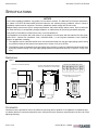
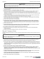
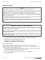
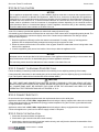
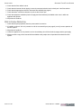
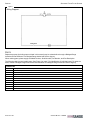
IMPORTANT FOR FUTURE REFERENCE
Please complete this information and retain
this manual for the life of the equipment:
Model #: __________________________
Serial #: __________________________
Date Purchased: ___________________
Owner’s Manual
Sectional Fryer Filter System
Model B24C-FF
WARNING
Improper installation, adjustment, alteration, service, or maintenance can cause property damage, injury, or death.
Read installation, operation, and maintenance instructions thoroughly before installing or servicing this equipment.
1100 Old Honeycutt Road, Fuquay-Varina, NC 27526 USA • www.blodgettrange.com
MANUAL 1184960
$18.00
SECTIONAL FRYER FILTER SYSTEM
MANUAL SECTION SR
SAFETY PRECAUTIONS
SECTIONAL FRYER FILTER SYSTEM
SAFETY PRECAUTIONS
Before installing and operating this equipment, be sure everyone involved in its operation is fully trained and aware of
precautions. Accidents and problems can be caused by failure to follow fundamental rules and precautions.
The following symbols, found throughout this manual, alert you to potentially dangerous conditions to the operator,
service personnel, or to the equipment.
DANGER
This symbol warns of immediate hazards that will result in severe injury or death.
WARNING
This symbol refers to a potential hazard or unsafe practice that could result in injury or
death.
CAUTION
This symbol refers to a potential hazard or unsafe practice that could result in injury,
product damage, or property damage.
NOTICE
This symbol refers to information that needs special attention or must be fully understood,
even though not dangerous.
WARNING
FIRE HAZARD
FOR YOUR SAFETY
Do not store or use gasoline or other flammable vapors and liquids in the vicinity of cooking appliances.
Keep area around cooking appliances free and clear of combustibles.
Purchaser of equipment must post in a prominent location detailed instructions to be followed in the event the
operator smells gas. Obtain the instructions from the local gas supplier.
WARNING
BURN HAZARD
Contact with hot surfaces will cause severe burns. Always use caution when operating cooking appliances.
WARNING
EXPLOSION AND ASPHYXIATION HAZARD
In the event a gas odor is detected, shut down equipment at the main gas shut-off valve and immediately call
the emergency phone number of your gas supplier.
Improper ventilation can result in headaches, drowsiness, nausea, and could result in death. Do not obstruct the
flow of combustion and ventilation air to and from cooking appliances.
WARNING
ELECTRIC SHOCK HAZARD
For appliances that use electric power, disconnect the power to the appliance before cleaning. Do not remove
panels that require tools to remove.
NOTICE
Blodgett Range appliances are intended for commercial use only. Not for household use.
Warranty will be void if service work is performed by other than a qualified technician, or if other than genuine
Blodgett Range replacement parts are installed.
Give this Owner’s Manual and important papers to the proper authority to retain for future reference.
Copyright © 2002 by Blodgett Range. All rights reserved. Published in the United States of America.
PAGE 2 OF 20
OWNER’S MANUAL 1184960
SECTIONAL FRYER FILTER SYSTEM
INTRODUCTION
INTRODUCTION
Congratulations! You have purchased one of the finest pieces of heavy-duty commercial cooking equipment on the
market.
You will find that your new equipment, like all Blodgett Range equipment, has been designed and manufactured to
meet the toughest standards in the industry. Each piece of Blodgett Range equipment is carefully engineered and
designs are verified through laboratory tests and field installations. With proper care and field maintenance, you will
experience years of reliable, trouble-free operation. For best results, read this manual carefully.
RETAIN THIS MANUAL FOR FUTURE REFERENCE.
This manual is for the Blodgett Range Sectional Fryer Filter System model B24C-FF.
The serial plate is located inside the cabinet door (see Figure 1 below).
Read these instructions carefully before attempting installation. Installation and initial startup should be performed by
a qualified installer. Unless the installation instructions for this product are followed by a qualified service technician (a
person experienced in and knowledgeable with the installation of commercial gas and/or electric cooking equipment)
then the terms and conditions on the Manufacturer’s Limited Warranty will be rendered void and no warranty of any
kind shall apply.
In the event you have questions concerning the installation, use, care, or service of the product, write to:
Blodgett Range
1100 Old Honeycutt Road
Fuquay-Varina, North Carolina 27526 USA
Figure 1
Location of Serial Plate
Location of Serial Plate
OWNER’S MANUAL 1184960
PAGE 3 OF 20
SPECIFICATIONS
SECTIONAL FRYER FILTER SYSTEM
SPECIFICATIONS
NOTICE
Local codes regarding installation vary greatly from one area to another. The National Fire Protection Association,
Inc. states in its NFPA 96 latest edition that local codes are the “authority having jurisdiction” when it comes to
installation requirements for equipment. Therefore, installations should comply with all local codes.
Blodgett Range reserves the right to change specifications and product design without notice. Such revisions do
not entitle the buyer to corresponding changes, additions, or replacements for previously purchased equipment.
This product is intended for commercial use only, not for household use.
The installation must conform with local codes, or in the absence of local codes, with the National Fuel Gas Code,
ANSI Z223.1, Natural Gas Installation Code, CAN/CGA-B149.1, or the Propane Installation Code CAN/CGAB149.2, as applicable, including:
1. The appliance and its individual shutoff valve must be disconnected from the gas supply piping system during
any pressure testing of that system at test pressures in excess of 1/2 psi (3.45 kPa).
2. The appliance must be isolated from the gas supply piping system by closing its individual manual shutoff valve
during any pressure testing of the gas supply piping system at test pressures equal to or less than 1/2 psi (3.45
kPa).
DIMENSIONS
Figure 2
Dimensions are in inches and (millimeters).
Flue riser for “deep” depth-option extends rearward 6"
(drain pan size is the same as for “standard” depth).
36" Flue Riser
41-3/4" (1060)
38" (965)
35-3/4" (908)
32" (813)
24" Flue Riser
72"
(1829)
Front Gas
Manifold
Height Depth
44.0
(1118)
45.0
(1143)
Weight
200 lbs
(91 kg)
Optional drain pan is 12-1/4" (311 mm) wide
and 20" (508 mm) front-to-back.
32"
(813)
4"
(102)
33-3/4"
(859)
6" (152)
2"
(51)
FRONT VIEW
Volume
45.5
52.1 cu ft
(1156) (1.48 cu m)
2-1/2" (64)
60"
(1524)
36" 30"
(914) (762)
SHIPPING CRATE DIMENSIONS & WEIGHT
Width
SIDE VIEW
24"
(610)
TOP VIEW
CLEARANCES
Clearance must be provided in front of the cabinet for servicing and for operation. If the appliance is installed as part
of a battery that has a continuous shared flue riser, follow the minimum clearance requirements for the flue riser of the
adjoining section(s).
PAGE 4 OF 20
OWNER’S MANUAL 1184960
SECTIONAL FRYER FILTER SYSTEM
SPECIFICATIONS
GAS SUPPLY
The Sectional Fryer Filter System does not use any gas, but it does have a 1-1/4" front gas manifold the couples to
the adjacent sectional unit(s).
ELECTRICITY SUPPLY
The Sectional Fryer Filter System requires electric power (50Hz or 60Hz single-phase AC). 120V models draw a
maximum of 6.5 amps, and have a 7-foot (2134 mm) power cord with a grounded plug. 230V models draw a
maximum of 2.6 amps, and have a terminal block for connection to a single-phase 230V source.
The appliance, when installed, must be electrically grounded in accordance with local codes, or in the absence of
local codes, with the National Electrical Code, ANSI/NFPA 70, or the Canadian Electrical Code, CSA C22.2, as
applicable.
VENTILATION
WARNING
Improper ventilation can result in personal injury or death. Ventilation which fails to properly remove flue products
can cause headaches, drowsiness, nausea, or could result in death.
All gas appliances must be installed in such a manner that the flow of combustion and ventilation air is not
obstructed. Provisions for adequate air supply must be provided.
NOTICE
Proper ventilation is the owner’s responsibility. Any problem due to improper ventilation will not be covered by the
warranty.
Be sure to inspect and clean the ventilation system according to the ventilation equipment manufacturer’s
instructions.
The Sectional Fryer Filter System is electrically powered, and so does not require combustion air. However, the flue
riser may contain exhaust gasses from adjoining appliances that share an optional continuous flue riser. Follow the
ventilation requirements for the adjoining section(s).
OWNER’S MANUAL 1184960
PAGE 5 OF 20
OPERATION
SECTIONAL FRYER FILTER SYSTEM
OPERATION
DANGER
EXPLOSION HAZARD
In the event a gas odor is detected, shut down equipment at the main shut off valve. Immediately call the
emergency phone number of your gas supplier.
WARNING
BURN HAZARD
CONTACT WITH HOT OIL WILL CAUSE SEVERE BURNS. ALWAYS USE CAUTION. OIL AT 200°F IS MORE
DANGEROUS THAN BOILING WATER.
The fryer filter system is contained in a cabinet that is part of a battery that includes deep fryers (see Figure 3). The
frypot-drains of the fryers are connected to a pipe that drains into a filter pan in the bottom of the filter cabinet. When
the power switch of the filter system is turned on, a pump draws the drained oil through a filter on the bottom of the
filter pan to remove breading and other impurities, and pumps the oil out of a discharge hose. The discharge hose can
be positioned to return the filtered oil to a frypot, to pump it into a container for disposal, or to pump it into a container
for storage while the frypot is cleaned.
Figure 3
Fryer Filter System Operation
Filter Discharge Hose
Drain Pan
Fryer Drain Pipe
(Cabinet Doors Not Shown)
PAGE 6 OF 20
OWNER’S MANUAL 1184960
SECTIONAL FRYER FILTER SYSTEM
OPERATION
Figure 4
Fryer Filter System Components
Power Switch
Filter-Pan Hose
Quick Disconnect
Stainless
Steel Hose
Discharge Hose
Quick Disconnect
Filter Pan
Fryer Drain
Pipe Outlet
Filter-Paper
Hold-Down Rack
Stainless Steel
Hose with Quick
Disconnect
Fryer Drain
Pipe Nipple
Filter-Paper Hold-Down
Rack with Latches
Filter Pan
Filter Pan
Wire Rack
FILTERING FRYER OIL
The oil of deep fryers should be filtered regularly to promote longer oil life.
1. Wear thermal oven mitts during this procedure to prevent burns from hot oil and metal surfaces of the fryer.
2. Make sure that two sheets of filter are properly positioned in the filter pan as described on page 10.
3. Set the thermostat of the fryer to the OFF position.
OWNER’S MANUAL 1184960
PAGE 7 OF 20
OPERATION
SECTIONAL FRYER FILTER SYSTEM
WARNING
Failure to make sure that the thermostat is in the OFF position during the following procedure may result in
equipment damage and/or personal injury.
4. Stir 8 ounces of Blodgett Range filter powder into the oil of the fryer. The filter powder helps extend oil life by
removing impurities.
5. Allow the oil to cool for 3 minutes after adding the filter powder.
6. Slowly open the drain valve handle beneath the frypot. The drain is opened by turning the handle so that it is
aligned with the drain outlet pipe. Use care when opening this valve to avoid being splashed by hot oil. If
necessary, use a small diameter brush to ream-out the drain from inside the frypot to open any clogs which might
develop as the oil drains
7. Connect the filter discharge hose to the quick disconnect fitting (see Figure 4). Always make sure that the hose
coupling is securely mated to the quick disconnect fitting before turning on the pump.
8. Position the wand end of the filter discharge hose over the now empty frypot. Always grasp the filter discharge
hose by the wooden sleeve near the wand end.
9. Place the filter’s power switch in the ON position.
10. Leave the fryer’s drain valve open to allow the filtered oil being pumped to the frypot to drain out the bottom
through the drain valve. Use a large brush to “wash-down” the frypot with the hot oil as it circulates through the
frypot. Use care to avoid being splashed and burned by the hot oil. Continue doing this for at least 2 minutes.
11. Close the fryer drain valve.
12. Allow all of the filtered oil to be pumped to the frypot. The oil will begin to bubble as the pumping is completed
and air fills the filter discharge hose. Place the pump switch in the OFF position.
13. If necessary, add oil to the fryer to bring the oil level up to the proper level.
14. Adjust the fryer thermostat to the desired cooking temperature, and heat the oil until it reaches the proper
cooking temperature.
15. Replace the filter paper (see page 10) daily, or more often, if necessary.
“BOIL-OUT” CLEANING OF FRYER
The fryer cleaning process known as a “boil-out” should be performed when necessary, and every time the fryer oil is
replaced.
WARNING
Perform the steps of this procedure as described to avoid possible equipment damage, violation of warranty
provisions, or personal injury.
1. Wear thermal oven mitts during this procedure to protect your skin from bums due to splashing of hot liquids.
2. Make sure that two sheets of filter are properly positioned in the filter pan as described on page 10.
3. If the oil in the fryer is “cold” (that is, at room temperature), first heat the oil briefly so that it is liquid enough to be
removed by the filter system. Turn the fryer thermostat to 150°F and heat the oil until the burners go out. Stir the
oil well to make sure that it is fully dissolved. Stirring may cause the burners to come on again briefly. Wait for the
burners go out again.
4. Place the fryer thermostat in the OFF position and wait two minutes.
5. Slowly open the drain valve handle beneath the frypot. The drain is opened by turning the handle so that it is
aligned with the drain outlet pipe. Use care when opening this valve to avoid being splashed by hot oil. If
necessary, use a small diameter brush to ream-out the drain from inside the frypot to open any clogs which might
develop as the oil drains.
6. Connect the filter discharge hose to the quick disconnect fitting (see Figure 4). Always make sure that the hose
coupling is securely mated to the quick disconnect fitting before turning on the pump.
7. Position the wand end of the filter discharge hose over the now empty frypot. Always grasp the filter discharge
hose by the wooden sleeve near the wand end.
8. Place the filter’s power switch in the ON position.
PAGE 8 OF 20
OWNER’S MANUAL 1184960
SECTIONAL FRYER FILTER SYSTEM
OPERATION
9. Leave the fryer’s drain valve open to allow the filtered oil being pumped to the frypot to drain out the bottom
through the drain valve. Use a large brush to “wash-down” the frypot with the hot oil as it circulates through the
frypot. Use care to avoid being splashed and burned by the hot oil. Continue doing this for at least 2 minutes.
10. When all accumulated breading and crumbs have been washed from the bottom of the frypot, place the filter
power switch in the OFF position and allow the oil to drain.
11. When all the oil has drained out of the frypot, close the frypot drain valve.
WARNING
ALWAYS MAKE SURE THAT THE CONTAINERS THAT ARE USED IN THE NEXT STEP WILL SAFELY
HOLD HOT OIL. Plastic is generally not safe as it may melt and break. Metal containers that do not leak
are preferable to containers made of other materials. Failure to exercise the this precaution may result in
serious personal injury.
12. Position an appropriate container (or containers) to hold the fryer oil while the frypot is being cleaned.
REMEMBER THAT YOU WILL BE REMOVING APPROXIMATELY 5 GALLONS OF OIL. Make sure that the
container(s) that you have selected will hold all of the oil. The oil that you will remove weighs 45 to 65 pounds,
and is still very hot. Placing the oil in two or more containers makes for a lighter load and decreases the
possibility of injury by splashing.
13. Position the wand end of the filter discharge hose over a container that you have positioned to receive the oil
from the filter. Always grasp the filter discharge hose by the wooden sleeve near the wand end.
14. Place the filter’s power switch in the ON position to pump the oil out through the filter discharge hose.
15. When all the oil has been removed from the drain pan, place the filter’s power switch in the OFF position.
16. Disconnect the filter discharge hose at the quick disconnect fitting. Hold both ends of the hose at the same height
to avoid spilling oil that may be in the hose. Carefully drain the hose into the container that is holding the oil.
17. Clean the filter pan using the procedure on page 10, except do NOT put the drain pan back into the filter cabinet.
18. Make sure that the fryer’s drain valve is closed.
19. Fill the frypot with water to the oil-level mark located on the back of the frypot interior.
20. Carefully add Blodgett Range Boil Out to the water following the directions on the container.
21. Set the fryer’s thermostat to 200°F.
CAUTION
DO NOT UNDER ANY CIRCUMSTANCES LEAVE THE FRYER UNATTENDED DURING THIS
PROCEDURE AS THE HEAT MUST BE CAREFULLY MONITORED TO PREVENT THE FRYPOT FROM
OVERFLOWING DUE TO BOILING. OVERFLOW OF THE FRYPOT MAY RESULT IN SERIOUS
EQUIPMENT DAMAGE.
22. Allow the cleaning solution to heat for 20 minutes. Scrub the interior of the frypot with the large pot brush during
this period to remove build-up.
23. Position a heat-resistant container (for example, a pail) beneath the drain-pipe outlet inside the filter cabinet.
Slowly open the fryer’s drain valve to allow the cleaning solution to drain into the container. Be careful not to over
fill the container.
24. Close the fryer’s drain valve.
25. Rinse the inside of the frypot with fresh water, then open the fryer’s drain valve to drain the rinse water into the
container in the filter cabinet.
26. Mop-out excess water from the frypot with a dry cloth.
27. Close the fryer’s drain valve.
28. Disconnect the filter discharge hose, rinse it out, and put it away.
29. Place the filter pan in the filter cabinet and secure its hose connection with the quick disconnect fitting (push
upward on the wooden ring while inserting the end of the hose).
30. Re-attach the drain-pipe nipple.
31. If the oil is to be reused, carefully pour it into the fryer’s frypot. Otherwise, properly dispose of the oil and refill the
fryer’s frypot according to the procedure described in the fryer’s manual. If necessary, add oil to the frypot to
bring the oil level up to the proper level.
OWNER’S MANUAL 1184960
PAGE 9 OF 20
CLEANING & MAINTENANCE
SECTIONAL FRYER FILTER SYSTEM
CLEANING & MAINTENANCE
WARNING
BURN HAZARD
CONTACT WITH HOT OIL WILL CAUSE SEVERE BURNS. ALWAYS USE CAUTION. OIL AT 200°F IS MORE
DANGEROUS THAN BOILING WATER.
Blodgett Range appliances are sturdily constructed of the best materials and are designed to provide durable service
when treated with ordinary care. To expect the best performance, your equipment must be maintained in good
condition and cleaned daily. Naturally, the periods for this care and cleaning depend on the amount and degree of
usage.
Following cleaning procedures will enhance long life for your equipment. Climatic conditions (such as salt air) may
require more thorough and frequent cleaning or the life of the equipment could be adversely affected.
Keep exposed, cleanable areas of the filter system clean at all times. In most situations, one layer of filter paper is
replaced each day, while the filter pan is cleaned when the connected fryers are cleaned. Figure 4 on page 7 shows
the filter-pan components mentioned in the following cleaning procedures.
DAILY REPLACEMENT OF FILTER PAPER
Two sheets of filter paper are used in the filter pan. During normal operation, the top sheet is discarded on a daily
basis. The bottom sheet is then placed on top of a new sheet of filter paper. Both sheets should be changed following
a “boil-out” cleaning the connected fryers.
The following procedure for replacement of filter paper on a daily basis:
1. Check that the filter pan does not contain oil, and that the power switch is in the OFF position.
2. Check that the drain valves of all connected fryers are in the closed position.
3. If necessary, allow the filter pan to cool.
4. Remove the drain-pipe nipple from the end of the drain-pipe outlet. (The drain-pipe nipple minimizes the
splashing of hot oil when a frypot is drained into the filter pan.)
5. Disconnect the drain pan’s stainless steel hose from the quick-disconnect fitting by pushing upward on the
wooden ring of the quick-disconnect and exerting downward pressure on the connector at the end of the hose.
6. Pull the filter pan forward and out of the filter system cabinet.
7. Remove accumulated breading and residue from the surface of the filter paper with a metal crumb shovel.
Remove residue from the small ledge which surrounds the filter-paper hold-down frame.
8. Release the four latches that secure the filter-paper hold-down frame, and remove the hold-down frame from the
filter pan.
9. Beginning at one end of the filter pan, carefully roll-up the top-sheet of filter paper and discard it.
10. Lift the edge of the bottom-sheet of filter paper and slip a clean sheet of filter paper beneath it.
11. Place the filter-paper hold-down rack on top of the filter paper and secure it with the four latches.
12. Place the filter pan in the filter cabinet and secure its hose connection with the quick disconnect fitting (push
upward on the wooden ring while inserting the end of the hose).
13. Re-attach the drain-pipe nipple.
CLEANING THE FILTER PAN
The filter pan should be thoroughly cleaned as needed. Use only Blodgett Range Cleanser or a cleanser such as Ajax
or Comet to clean the interior surfaces and components of the filter pan. LIQUID DISHWASHING DETERGENTS
MAY LEAVE RESIDUES WHICH REDUCE OIL LIFE. The cleaning procedure is as follows:
1. Check that the filter pan does not contain oil, and that the power switch is in the OFF position.
2. Check that the drain valves of all connected fryers are in the closed position.
PAGE 10 OF 20
OWNER’S MANUAL 1184960
SECTIONAL FRYER FILTER SYSTEM
CLEANING & MAINTENANCE
3. If necessary, allow the filter pan to cool.
4. Remove the drain-pipe nipple from the end of the drain-pipe outlet. (The drain-pipe nipple minimizes the
splashing of hot oil when a frypot is drained into the filter pan.)
5. Disconnect the drain pan’s stainless steel hose from the quick-disconnect fitting by pushing upward on the
wooden ring of the quick-disconnect and exerting downward pressure on the connector at the end of the hose.
6. Pull the filter pan forward and out of the filter system cabinet.
7. Release the four latches that secure the filter-paper hold-down frame. Remove the hold-down frame from the
filter pan and place it in a sink for cleaning
8. Remove and discard both sheets of filter paper.
9. Remove the wire rack beneath the filter paper and placed it in a sink for cleaning.
10. Drain any remaining oil from the bottom of the filter pan into a proper waste receptacle. You must lift and tilt the
filter pan to accomplish this. The filter pan is somewhat heavy, so you may need assistance.
11. Clean the interior of the filter pan with one of the recommended cleaners. Clean beneath the oil pick-up tube
located in the bottom rear of the filter pan with a knife blade or other similar thin, flat instrument. Rinse the pan
interior and mop out excess water with a dry cloth or paper toweling.
12. Clean, rinse, and dry the wire rack and filter-paper hold-down frame that you placed in the sink earlier.
13. Place the wire rack in the bottom of the drain pan.
14. Place two layers of new filter paper on top of the wire frame.
15. Place the filter-paper hold-down rack on top of the filter paper and secure it with the four latches.
16. Place the filter pan in the filter cabinet and secure its hose connection with the quick disconnect fitting (push
upward on the wooden ring while inserting the end of the hose).
17. Re-attach the drain-pipe nipple.
CLEANING STAINLESS-STEEL SURFACES
To remove normal dirt, grease and product residue from stainless steel surfaces that operate at LOW temperature,
use ordinary soap and water (with or without detergent) applied with a sponge or cloth. Dry thoroughly with a clean
cloth.
To remove BAKED-ON grease and food splatter, or condensed vapors; apply cleanser to a damp cloth or sponge and
rub cleanser on the metal in the direction of the polishing lines on the metal. Rubbing cleanser, as gently as possible,
in the direction of the polished lines will not mar the finish of the stainless steel. NEVER RUB WITH A CIRCULAR
MOTION. Soil and burnt deposits which do not respond to the above procedure can usually be removed by rubbing
the surface with SCOTCH-BRITE scouring pads or STAINLESS scouring pads. DO NOT USE ORDINARY STEEL
WOOL as any particles left on the surface will rust and further spoil the appearance of the finish. NEVER USE A
WIRE BRUSH, STEEL SCOURING PADS (EXCEPT STAINLESS), SCRAPER, FILE OR OTHER STEEL TOOLS.
Surfaces which are marred collect dirt more rapidly and become more difficult to clean. Marring also increases the
possibility of corrosive attack. Refinishing may then be required.
“Heat tint” is darkened areas that sometimes appear on stainless steel surfaces where the area has been subjected to
excessive heat. These darkened areas are caused by thickening of the protective surface of the stainless steel and
are not harmful. Heat tint can normally be removed by the foregoing, but tint which does not respond to this procedure
calls for a vigorous scouring in the direction of the polish lines using SCOTCH-BRITE scouring pads or a STAINLESS
scouring pad in combination with a powered cleanser. Heat tint may be lessened by reducing heat to equipment
during slack periods.
BLACK BAKED-ENAMEL SURFACES
Allow appliance to cool somewhat after use and wash black baked-enamel surfaces with a hot, mild detergent or soap
solution. In particular, clean off all grease deposits. Dry thoroughly with a dry cloth.
OWNER’S MANUAL 1184960
PAGE 11 OF 20
INSTALLATION
SECTIONAL FRYER FILTER SYSTEM
INSTALLATION
NOTICE
These installation procedures must be followed by qualified personnel or warranty will be void.
Local codes regarding installation vary greatly from one area to another. The National Fire Protection Association,
Inc. states in its NFPA 96 latest edition that local codes are the “authority having jurisdiction” when it comes to
installation requirements for equipment. Therefore, installations should comply with all local codes.
The installation must conform with local codes, or in the absence of local codes, with the National Fuel Gas Code,
ANSI Z223.1, Natural Gas Installation Code, CAN/CGA-B149.1, or the Propane Installation Code CAN/CGAB149.2, as applicable, including:
1. The appliance and its individual shutoff valve must be disconnected from the gas supply piping system during
any pressure testing of that system at test pressures in excess of 1/2 psi (3.45 kPa).
2. The appliance must be isolated from the gas supply piping system by closing its individual manual shutoff valve
during any pressure testing of the gas supply piping system at test pressures equal to or less than 1/2 psi (3.45
kPa).
STEP 1: UNPACKING
IMMEDIATELY INSPECT FOR SHIPPING DAMAGE
All containers should be examined for damage before and during unloading. The freight carrier has assumed
responsibility for its safe transit and delivery. If damaged equipment is received, either apparent or concealed, a
claim must be made with the delivering carrier.
Apparent damage or loss must be noted on the freight bill at the time of delivery. The freight bill must then be
signed by the carrier representative (Driver). If the bill is not signed, the carrier may refuse the claim. The carrier
can supply the necessary forms.
A request for inspection must be made to the carrier within 15 days if there is concealed damage or loss that is not
apparent until after the equipment is uncrated. The carrier should arrange an inspection. Be certain to hold all
contents plus all packing material.
1. Cut the banding straps and remove the corrugated cardboard surrounding the Sectional Fryer Filter System. Do
not remove any of the attached tags or labels until the appliance is installed and working properly.
2. Cut the banding strap holding the appliance to the wooden skid.
3. If the appliance is to be installed on 6" legs, go to Step 2a.
If the appliance is to be installed on 6" casters, go to Step 2b.
If the appliance is to be installed on a caster frame, go to Step 3.
STEP 2A: ATTACH LEGS
A set of four legs is packed with units ordered with legs. (For units ordered with casters, go to Step 2b.)
A threaded leg pad is fastened to the base frame at each corner. Each leg has a corresponding mating thread. The
legs can be adjusted to overcome a slightly uneven floor.
1. Raise the appliance sufficiently to allow the legs to be attached. For safety, “shore up” and support the appliance
with an adequate blocking arrangement strong enough to support the load.
2. Screw the legs into the holes in the centers of the leg pads.
3. Lower the appliance gently onto a level surface. Never drop or allow the appliance to fall.
4. Go on to Installation Step 3.
PAGE 12 OF 20
OWNER’S MANUAL 1184960
SECTIONAL FRYER FILTER SYSTEM
INSTALLATION
STEP 2B: ATTACH CASTERS
NOTICE
For an appliance equipped with casters, (1) the installation shall be made with a connector that complies with the
Standard for Connectors for Movable Gas Appliances, ANSI Z21.69 or Connectors for Moveable Gas Appliances,
CAN/CGA-6.16, and a quick-disconnect device that complies with the Standard for Quick-Disconnect Devices for
Use With Gas Fuel, ANSI Z21.41, or Quick Disconnect Devices for Use with Gas Fuel, CAN1-6.9, (2) adequate
means must be provided to limit the movement of the appliance without depending on the connector and the
quick-disconnect device or its associated piping to limit the appliance movement and (3) the restraining means
should be attached to a frame member on the back of the unit.
A set of four casters is packed with appliances ordered with casters (instead of legs).
A threaded leg pad is fastened to the base frame at each corner. Each caster has a corresponding mating thread. The
casters can be adjusted to overcome a slightly uneven floor. Casters are provided with a Zerk fitting for proper
lubrication when required.
1. Raise the appliance sufficiently to allow the casters to be attached. For safety, “shore up” and support the
appliance with an adequate blocking arrangement strong enough to support the load.
2. Screw the casters into the holes in the centers of the leg pads. Install the casters that have a locking brake under
the front of the appliance.
3. Lower the appliance gently onto a level surface. Never drop or allow the appliance to fall.
NOTICE
Adequate means must be provided to limit the movement of the appliance without depending on the connector and
the quick-disconnect device or its associated piping to limit the appliance movement.
The restraining means should be attached to a frame member on the back of the unit.
STEP 3: CONNECT TO ADJOINING FRYER SECTIONS
Follow the battery connection procedure described in the manual(s) for the adjoining section(s) of the battery.
Custom assembly instructions for the internal piping of the oil drain piping from the adjoining fryer(s) to the Sectional
Fryer Filter System cabinet will be furnished with each individual battery.
CAUTION
ALL PIPE JOINTS AND CONNECTIONS MUST BE TESTED THOROUGHLY FOR GAS LEAKS. USE ONLY
SOAPY WATER FOR TESTING ON ALL GASES. NEVER USE AN OPEN FLAME TO CHECK FOR GAS LEAKS.
ALL CONNECTIONS MUST BE CHECKED FOR LEAKS AFTER THE APPLIANCE HAS BEEN PUT INTO
OPERATION. TEST PRESSURE SHOULD NOT EXCEED 14" W.C.
STEP 4: CONNECT ELECTRICITY
Be sure that the input voltage and phase match the requirements shown on the serial plate.
Appliances ordered with a 115V, 60Hz, single-phase electrical rating are factory-supplied with a three-wire cord with
a three-prong plug that fits any standard three-prong grounded receptacle. Plug the cord into a grounded outlet able
to supply at least 6.2 amperes.
Appliances ordered with a 230V, 60Hz, single-phase electrical rating are factory-equipped with a terminal block.
Connect the appliance to a power source able to supply at least 2.6 amperes.
STEP 5: CHECK THE INSTALLATION
1. Check that all screws and bolts are tightened.
2. Check that the gas connection has been made correctly.
3. Check that the electrical connection has been made correctly, and verify that the electrical characteristics of the
electric power source match the appliance.
OWNER’S MANUAL 1184960
PAGE 13 OF 20
INSTALLATION
SECTIONAL FRYER FILTER SYSTEM
4. Check that the filter cabinet is level.
5. Check that the internal oil drain piping is correctly connected a drains into the drain pan in the filter cabinet.
6. Check that the appropriate minimum clearances are satisfied (see page 4).
7. Check that there is sufficient clearance to pull-out the oil drain pan.
8. Check that adequate ventilation (fresh air supply and hood exhaust) is available to the room in which the
appliance will operate.
9. Wipe clean all surfaces.
STEP 6: CHECK OPERATION
1. Check that the pump operates when the power switch is turned on.
2. If possible, perform a “boil out” procedure on all the connected fryers (see page 8) to verify correct operation of
the filter system.
3. Wipe clean all surfaces.
4. Unless the appliance is to be placed in service immediately, shut off the electricity supply and the gas supply.
5. Make sure that a copy of this manual will be available to the people who will operate and maintain the filter
system.
PAGE 14 OF 20
OWNER’S MANUAL 1184960
SECTIONAL FRYER FILTER SYSTEM
SERVICE
SERVICE
WARNING
ADJUSTMENTS AND SERVICE WORK MAY BE PERFORMED ONLY BY A QUALIFIED TECHNICIAN WHO IS
EXPERIENCED IN, AND KNOWLEDGEABLE WITH, THE OPERATION OF COMMERCIAL COOKING
EQUIPMENT. TO ASSURE YOUR CONFIDENCE, CONTACT YOUR AUTHORIZED SERVICE AGENCY FOR
RELIABLE SERVICE, DEPENDABLE ADVICE OR OTHER ASSISTANCE, AND FOR GENUINE FACTORY
PARTS.
NOTICE
INSTALLATION OF OTHER THAN GENUINE BLODGETT RANGE PARTS WILL VOID THE WARRANTY ON
THIS EQUIPMENT.
The serial plate is located inside the cabinet door (see Figure 1 on page 3).
PUMP MOTOR DOES NOT OPERATE
If the pump motor does not operate, check the following:
1. Check that the electric power source has power.
2. Disconnect the power and use a multimeter to verify that the power switch is functioning properly. If it is not,
replace the power switch.
3. If the power switch is functioning properly, reconnect the power and place the power switch in the ON position.
Then check the voltage at the pump motor. If the pump motor is not receiving the correct voltage, check the
wiring. If the pump motor is receiving the correct voltage, but still does not run, replace the pump motor.
FILTER SYSTEM PUMPS SLOWLY
If the pump operates, but the filter system pumps slowly, check the following:
1. Check that the filter paper on the bottom of the drain pan is not clogged or torn.
2. Check that the filter-paper hold-down frame in the drain pan is latched on all four sides.
3. Check that the stainless steel flexible hose that connects the drain pan to the pump plumbing is not crimped or
collapsed. If necessary, replace the hose.
4. Check that the quick-disconnect fittings securely lock onto the ends of the hose. If the end of the hose will not
lock into the corresponding quick-disconnect, remove and replace the quick-disconnect fitting.
5. Disconnect the pump from the filter lines and check that there are no obstructions in the plumbing leading to and
from the pump.
6. If no obstructions exist in the plumbing leading to and from the pump, remove and replace the filter pump
assembly.
OWNER’S MANUAL 1184960
PAGE 15 OF 20
SERVICE
SECTIONAL FRYER FILTER SYSTEM
Figure 5
Wiring Diagram
PARTS
Replacement parts (including parts not listed in this manual) may be ordered either through a Blodgett Range
Authorized Parts Distributor or a Blodgett Range Authorized Service Agency.
When ordering parts, please supply the Model Number, Serial Number, Part Number, and Part Description.
The following table lists serviceable parts. (See Figure 4 on page 7 for identification of individual parts). For parts not
listed, contact a Blodgett Range Authorized Parts Distributor or a Blodgett Range Authorized Service Agency.
Parts List
Part Number
1173416
1173417
1173418
1174288
1174289
1174290
1174291
1174292
1174293
1174294
PAGE 16 OF 20
Description
FILTER PAPER (100 SHEETS PER BOX)
FRYER BOIL OUT
FILTER POWDER (25 LB. BAG)
FILTER HOLD DOWN RACK WITH LATCHES
FILTER PAN
PUMP
FILTER PAN DRAIN RACK
OIL RETURN WAND
OIL QUICK DISCONNECT
18" STAINLESS STEEL FLEXIBLE HOSE
OWNER’S MANUAL 1184960
SECTIONAL FRYER FILTER SYSTEM
Notes:
OWNER’S MANUAL 1184960
PAGE 17 OF 20
SECTIONAL FRYER FILTER SYSTEM
Notes:
PAGE 18 OF 20
OWNER’S MANUAL 1184960
SECTIONAL FRYER FILTER SYSTEM
Notes:
OWNER’S MANUAL 1184960
PAGE 19 OF 20
SECTIONAL FRYER FILTER SYSTEM
SECTIONAL FRYER FILTER SYSTEM
A product with the Blodgett Range name incorporates the best in durability and low maintenance. We all
recognize, however, that replacement parts and occasional professional service may be necessary to extend the
useful life of this appliance. When service is needed, contact a Blodgett Range Authorized Service Agency, or your
dealer. To avoid confusion, always refer to the model number, serial number, and type of your appliance.
Blodgett Range
1100 Old Honeycutt Road, Fuquay-Varina, NC 27526
www.blodgettrange.com
PAGE 20 OF 20
OWNER’S MANUAL 1184960