1
PEB-10G Series
PEB-10G/57840-2S
PEB-10G/57811-1S
10 Gigabit/s Ethernet card
User Guide
E9427
First Edition
June 2014
Copyright © 2014 ASUSTeK COMPUTER INC. All Rights Reserved.
No part of this manual, including the products and software described in it, may be reproduced, transmitted,
transcribed, stored in a retrieval system, or translated into any language in any form or by any means,
except documentation kept by the purchaser for backup purposes, without the express written permission
of ASUSTeK COMPUTER INC. (“ASUS”).
Product warranty or service will not be extended if: (1) the product is repaired, modified or altered, unless
such repair, modification of alteration is authorized in writing by ASUS; or (2) the serial number of the
product is defaced or missing.
ASUS PROVIDES THIS MANUAL “AS IS” WITHOUT WARRANTY OF ANY KIND, EITHER EXPRESS
OR IMPLIED, INCLUDING BUT NOT LIMITED TO THE IMPLIED WARRANTIES OR CONDITIONS OF
MERCHANTABILITY OR FITNESS FOR A PARTICULAR PURPOSE. IN NO EVENT SHALL ASUS, ITS
DIRECTORS, OFFICERS, EMPLOYEES OR AGENTS BE LIABLE FOR ANY INDIRECT, SPECIAL,
INCIDENTAL, OR CONSEQUENTIAL DAMAGES (INCLUDING DAMAGES FOR LOSS OF PROFITS,
LOSS OF BUSINESS, LOSS OF USE OR DATA, INTERRUPTION OF BUSINESS AND THE LIKE),
EVEN IF ASUS HAS BEEN ADVISED OF THE POSSIBILITY OF SUCH DAMAGES ARISING FROM ANY
DEFECT OR ERROR IN THIS MANUAL OR PRODUCT.
SPECIFICATIONS AND INFORMATION CONTAINED IN THIS MANUAL ARE FURNISHED FOR
INFORMATIONAL USE ONLY, AND ARE SUBJECT TO CHANGE AT ANY TIME WITHOUT NOTICE,
AND SHOULD NOT BE CONSTRUED AS A COMMITMENT BY ASUS. ASUS ASSUMES NO
RESPONSIBILITY OR LIABILITY FOR ANY ERRORS OR INACCURACIES THAT MAY APPEAR IN THIS
MANUAL, INCLUDING THE PRODUCTS AND SOFTWARE DESCRIBED IN IT.
Products and corporate names appearing in this manual may or may not be registered trademarks or
copyrights of their respective companies, and are used only for identification or explanation and to the
owners’ benefit, without intent to infringe.
ii
Contents
Contents....................................................................................................................... iii
About this guide.......................................................................................................... iv
How this guide is organized.............................................................................iv
Where to find more information........................................................................iv
Conventions used in this guide........................................................................ v
Typography...................................................................................................... v
PEB-10G Series specifications summary................................................................. vi
Chapter 1: Product introduction
1.1Welcome!..................................................................................................... 1-2
1.2
Package contents....................................................................................... 1-2
1.3
System requirements.................................................................................. 1-2
1.4
Card layout.................................................................................................. 1-3
1.5
Replacing the card bracket........................................................................ 1-4
Chapter 2: Boot Agent Configuration
2.1Broadcom NetXtreme Ethernet Boot Agent............................................. 2-2
2.1.1
Device Hardware Configuration Menu......................................... 2-4
2.1.2
MBA Configuration Menu............................................................. 2-4
2.1.3
iSCSI Boot Configuration............................................................. 2-6
2.1.4
NIC Partition Configuration Menu (PEB-10G/57840-2S only)... 2-10
Chapter 3: Driver installation
3.1Windows® Server OS Driver Installation................................................... 3-2
3.2
Linux OS Driver Installation....................................................................... 3-5
ASUS contact information........................................................................................... 1
iii
About this guide
This user guide contains the information you need when installing and configuring the server
management board.
How this guide is organized
This guide contains the following parts:
•
Chapter 1: Product introduction
This chapter describes the PEB-10G Series Ethernet card features and the new
technologies it supports.
•
Chapter 2: Boot Agent configuration
This chapter provides instructions on setting the Broadcom NetXtreme Ethernet Boot
Agent.
•
Chapter 3: Driver installation
This chapter provides instructions for installing the Ethernet card drivers on different
operating systems.
Where to find more information
Refer to the following sources for additional information and for product and software updates.
1.
ASUS websites
The ASUS website provides updated information on ASUS hardware and software
products. Refer to the ASUS contact information.
2.
Optional documentation
Your product package may include optional documentation, such as warranty flyers,
that may have been added by your dealer. These documents are not part of the
standard package.
iv
Conventions used in this guide
To make sure that you perform certain tasks properly, take note of the following symbols
used throughout this manual.
DANGER/WARNING: Information to prevent injury to yourself
when trying to complete a task.
CAUTION: Information to prevent damage to the components
when trying to complete a task.
IMPORTANT: Instructions that you MUST follow to complete a
task.
NOTE: Tips and additional information to help you complete a
task.
Typography
Bold text
Indicates a menu or an item to select.
Italics
Used to emphasize a word or a phrase.
<Key> Keys enclosed in the less-than and greater-than sign means
that you must press the enclosed key.
Example: <Enter> means that you must press the Enter or
Return key.
<Key1>+<Key2>+<Key3>
If you must press two or more keys simultaneously, the key
names are linked with a plus sign (+).
Example: <Ctrl>+<Alt>+<Del>
Command
Means that you must type the command exactly as shown,
then supply the required item or value enclosed in
brackets.
Example: At the DOS prompt, type the command line:
format a:
v
PEB-10G Series specifications summary
PEB-10G/57840-2S
Speed & Ports
Ethernet
Controller
PHY
Connector &
module type
Host Interface
Form factor
PEB-10G/57811-1S
10 Gigabit/s Ethernet
10 Gigabit/s Ethernet
Fiber; Dual Port
Fiber; Single Port
Broadcom 57840S
Broadcom 57811S
LC Fiber Optic
Supports SFP+ SR Optical module, SFP+ LR Optical module, Direct
Attached Copper*
PCI-E Gen3 x8
PCI-E Gen2 x8
4.72 in. x 1.77 in. (lower than standard low profile)
SMF up to 10km (LR)
Support Cable
Type
MMF 62.5/50um up to 300m (SR)
Passive Twin-AX up to 5m (SFP+ Direct Attach)
Features
PXE boot
iSCSI boot
* Please refer to ASUS website for Approved Vendor List (AVL).
** Specifications are subject to change without notice.
vi
Product introduction
This chapter offers the PEB-10G Series Ethernet card features
and the new technologies it supports.
Chapter 1: Product introduction
1
1.1Welcome!
Thank you for buying an ASUS® PEB-10G Series 10 Gigabit/s Ethernet card!
Before you start installing the Ethernet card, check the items in your package with the list
below.
1.2
Package contents
Check your package for the following items.
PEB-10G/57840-2S
Standard Gift Box Pack
Standard Bulk Pack
Support DVD
1
1 (per carton)
Low profile bracket
1
1
Small bracket for node*
1
1
Screws
4
4
1 pc per carton
5 pcs per carton
Packing Quantity
PEB-10G/57811-1S
Standard Gift Box Pack
Standard Bulk Pack
Support DVD
1
1 (per carton)
Low profile bracket
1
1
Small bracket for node*
1
1
4
4
1 pc per carton
5 pcs per carton
Screws
Packing Quantity
If any of the above items is damaged or missing, contact your retailer.
* The bundled small bracket for node is a proprietray bracket that supports ASUS
Z10PH-D16 series, ES4000 G3 series, and RS720Q-E8 series models, etc. The supported
list of models are subject to change without prior notice.
1.3
System requirements
Before you install the PEB-10G Series Ethernet card, check if the system meets the following
requirements:
•
Server or workstation motherboard with a PCI Express x8 or x16 card slot
•
Supported operating system:
Windows® and Linux operating systems (refer to the specification table or the ASUS
website for the latest updates).
1-2
Chapter 1: Product introduction
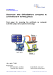
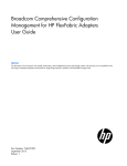
1.4
Card layout
PEB-10G/57840-2S
Front view
Back view
1.
LC Fiber Optic Connector 1
2.
LC Fiber Optic Connector 2
3.
PCI Express x8 interface
4.
SFP2LED2 LED
5.
SFP2LED1 LED
6.
PCIELINK1 LED
LED indications
Speed/Link
Status
SFP2LED1 /
SFP2LED2
Green
Description
10 Gbps link
Amber
1 Gbps link
Blinking
Data Activity
PCIELINK1
ASUS PEB-10G Series
Status
Description
Green
PCIE link
1-3
1.5
Replacing the card bracket
The PEB-10G Series Ethernet card is bundled with a full-length bracket, a low-profile bracket,
and an ASUS proprietary bracket. By default, the card is pre-installed with a full-length
bracket.
The proprietray bracket supports ASUS Z10PH-D16 series, ES4000 G3 series, and
RS720Q-E8 series models, etc. The supported list of models are subject to change without
prior notice.
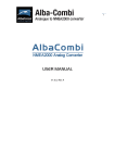
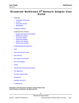
To replace the card bracket:
1. Get the PEB-10G Series Ethernet card and place it on a stable and flat surface.
Ensure that the printed circuit board (PCB) is facing down.
2. Remove the two screws that secures the PEB-10G Series Ethernet card to the card
bracket then remove the card bracket.
screw
default card bracket
screw
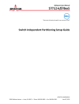
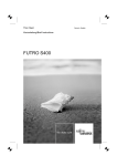
3. Get the replacement card bracket.
4. Align and insert the PEB-10G Series Ethernet card into the mounting hole of the card
bracket. Ensure that the screw holes on the PEB-10G Series Ethernet card matches
the screw holes of the card bracket.
5. Replace the screws that you removed earlier in step 2.
replacement card bracket
screw
screw
1-4
Chapter 1: Product introduction
Boot Agent Configuration
This chapter provides instructions on setting the Broadcom
NetXtreme Ethernet Boot Agent.
Chapter 2: Boot Agent Configuration
2
2.1Broadcom NetXtreme Ethernet Boot Agent
The Broadcom NetXtreme Ethernet Boot Agent provides hardware-based Ethernet card
configurations.
To start the Broadcom NetXtreme Ethernet Boot Agent and access the main screen:
1.
Turn on the system.
2.
During POST, press <Ctrl+S> when the following screen appears.
Broadcom NetXtreme Ethernet Boot Agent
Copyright (C) 2000-2013 Broadcom Corporation
All rights reserved.
Press Ctrl-S to enter Configuration Menu
3.
From the Device List screen, use the up/down arrow key to select an Ethernet device
to configure then press <Enter>. (PEB-10G/57840-2S only)
Comprehensive Configuration Management v7.8.21
Copyright (C) 2000-2013 Broadcom Corporation
All rights reserved.
Device List
<03:00:00> BCM57840 - C8:60:00:22:86:B7 MBA:v7.2.29 CCM:v7.8.21
<03:00:01> BCM57840 - C8:60:00:22:86:B9 MBA:v7.2.29 CCM:v7.8.21
Select Device to Configure
[Enter]:Enter Next Menu; [↑|↓]:Next Entry; [ESC]:Quit Menu
4.
From the Main Menu, use the up/down arrow key to select an item and press <Enter>
For PEB-10G/57840-2S:
Comprehensive Configuration Management v7.8.21
Copyright (C) 2000-2013 Broadcom Corporation
All rights reserved.
Main Menu
Device Hardware Configuration
MBA Configuration
iSCSI Boot Configuration
NIC Partition Configuration
Configure MBA Parameters
[Enter]:Enter Next Menu; [↑|↓]:Next Entry; [ESC]:Quit Menu
Current Adapter:Primary, Bus=03 Device=00 Func=00, MAC=C8:60:00:22:86:B7
2-2
Chapter 2: Boot Agent Configuration
For PEB-10G/57811-1S:
Comprehensive Configuration Management v7.8.21
Copyright (C) 2000-2013 Broadcom Corporation
All rights reserved.
Main Menu
Device Hardware Configuration
MBA Configuration
iSCSI Boot Configuration
Configure MBA Parameters
[Enter]:Enter Next Menu; [↑|↓]:Next Entry; [ESC]:Quit Menu
Current Adapter:Primary, Bus=03 Device=00 Func=00, MAC=C8:60:00:22:86:B7
ASUS PEB-10G Series
2-3
2.1.1
Device Hardware Configuration Menu
Comprehensive Configuration Management v7.8.21
Copyright (C) 2000-2013 Broadcom Corporation
All rights reserved.
Device Hardware Configuration
Multi-Function Mode
: SF
DCB Protocol
: Disabled
Max Number of PF MSIX Vectors: 0
Configure NIC Hardware Mode (Read Only)
[Enter]:Enter Next Menu; [↑|↓]:Next Entry; [ESC]:Quit Menu
Current Adapter:Primary, Bus=03 Device=00 Func=00, MAC=C8:60:00:22:86:B7
DCB Protocol [Disabled]
Configuration options: [Disabled] [Enabled]
2.1.2
MBA Configuration Menu
Comprehensive Configuration Management v7.8.21
Copyright (C) 2000-2013 Broadcom Corporation
All rights reserved.
MBA Configuration Menu
Option ROM
Boot Protocol
Boot Strap Type
Hide Setup Prompt
Setup Key Stroke
Banner Message Timeout
Link Speed
Pre-boot Wake On LAN
VLAN Mode
VLAN ID
Boot Retry Count
:
:
:
:
:
:
:
:
:
:
:
Enabled
Preboot Execution Environment (PXE)
Auto
Disabled
Ctrl-S
10 Seconds
10Gbps
Enabled
Disabled
1
0
Enable/Disable Option ROM
[←|→][Enter][Space]:Toggle Value; [↑|↓]:Next Entry; [ESC]:Quit Menu
Current Adapter:Primary, Bus=03 Device=00 Func=00, MAC=C8:60:00:22:86:B7
Option ROM [Enabled]
Configuration options: [Enabled] [Disabled]
Boot Protocol [Preboot Execution Environment (PXE)]
Configuration options: [Preboot Execution Environment (PXE)]
[Bootstrap Protocol (BOOTP)] [iSCSI] [FCoE] [None]
2-4
Chapter 2: Boot Agent Configuration
Boot Strap Type [Auto]
Configuration options: [Auto] [BBS] [Int18h] [Int19h]
Hide Setup Prompt [Disabled]
Configuration options: [Disabled] [Enabled]
Setup Key Stroke [Ctrl-S]
Configuration options: [Ctrl-S] [Ctrl-B]
Banner Message Timeout [10 Seconds]
Configuration options: [1 Second] – [14 Seconds]
Link Speed [10Gbps]
Configuration options: [10Gbps] [1Gbps]
Pre-boot Wake On LAN [Enabled]
Configuration options: [Enabled] [Disabled]
VLAN Mode [Disabled]
Configuration options: [Disabled] [Enabled]
VLAN ID [1]
Configuration options: [0] – [4094]
Boot Retry Count [0]
Configuration options: [0] – [7]
ASUS PEB-10G Series
2-5
2.1.3
iSCSI Boot Configuration
For PEB-10G/57840-2S:
Comprehensive Configuration Management v7.8.21
Copyright (C) 2000-2013 Broadcom Corporation
All rights reserved.
iSCSI Boot Main Menu
General Parameters
Initiator Parameters
1st Target Parameters
2nd Target Parameters
Secondary Device Parameters
Configure General Boot Parameters
[Enter]:Enter Next Menu; [↑|↓]:Next Entry; [ESC]:Quit Menu
Current Adapter:Primary, Bus=03 Device=00 Func=00, MAC=C8:60:00:22:86:B7
For PEB-10G/57811-1S:
Comprehensive Configuration Management v7.8.21
Copyright (C) 2000-2013 Broadcom Corporation
All rights reserved.
iSCSI Boot Main Menu
General Parameters
Initiator Parameters
1st Target Parameters
2nd Target Parameters
Configure General Boot Parameters
[Enter]:Enter Next Menu; [↑|↓]:Next Entry; [ESC]:Quit Menu
Current Adapter:Primary, Bus=03 Device=00 Func=00, MAC=C8:60:00:22:86:B7
2-6
Chapter 2: Boot Agent Configuration
General Parameters
TCP/IP Parameters via DHCP [Enabled]
This option applies to IPv4.
[Enabled] The iSCSI boot host software acquires the IP address from the DHCP
server.
[Disabled] The iSCSI boot host software acquires the static IP address.
iSCSI Parameters via DHCP [Enabled]
[Enabled] The iSCSI boot host software acquires its iSCSI target parameters from
the DHCP server.
[Disabled] The iSCSI boot host software acquires its iSCSI target parameters via the
static IP address, which is entered through the iSCSI Initiator Parameters
Configuration screen.
CHAP Authentication [Disabled]
[Enabled] Allows the iSCSI boot host software to use CHAP authentication when
connecting to the iSCSI target. Enter the CHAP ID and CHAP Secret in the
Initiator Parameters configuration screen.
[Disabled] Does not allow the iSCSI boot host software to use CHAP authentication
when connecting to the iSCSI target.
Boot to iSCSI Target [Enabled]
[Enabled] The iSCSI boot host software immediately attempts to boot from the iSCSI
target after successfully connecting to it.
[Disabled] The iSCSI boot host software does not attempt to boot from the iSCSI
target after successfully connecting to it. The control will then return to the
system BIOS so that the next boot device may be used.
ASUS PEB-10G Series
2-7
[One Time D
isabled] On the first system boot, the iSCSI boot host software does not
attempt to boot from the iSCSI target. On subsequent system reboots, the
iSCSI boot host software will attempt to boot from the iSCSI target. This
option is useful when doing a remote install of the OS to an iSCSI target.
•
When using iSCSI boot, set Boot to iSCSI Target to [Disabled] or [One Time Disabled].
•
When using iSCSI boot to install Windows Server 2008 OS, refer to
http://support.microsoft.com/kb/974072/EN-US to complete the process.
DHCP Vendor ID [BRCM ISAN]
Controls how the iSCSI boot host software interprets the Vendor Class ID field used in
the DHCP server. If DHCP is disabled, this value does not need to be specified. Enter
a new value in 0 to 32 characters.
Link Up Delay Time [0]
Decides how many seconds the iSCSI boot host software waits after an Ethernet link is
established before sending any data over the network. The valid values are 0 to 255.
Use TCP Timestamp [Disabled]
Enables or disables the TCP Timestamp option.
Configuration options: [Disabled] [Enabled]
Target as First HDD [Disabled]
When enabled, the iSCSI target drive appears as the first hard drive in the system.
Configuration options: [Disabled] [Enabled]
LUN Busy Retry Count [0]
Specifies the number of connection retries the iSCSI Boot initiator will attempt if the
iSCSI target LUN is busy. Configuration options: [0] – [60]
IP Version [IPv4]
Switches between the IPv4 or IPv6 protocol.
Configuration options: [IPv4] [IPv6]
Modifying this parameter erases all IP-related values.
2-8
Chapter 2: Boot Agent Configuration
Initiator Parameters
Key in the necessary parameters.
CComprehensive Configuration Management v7.8.21
Copyright (C) 2000-2013 Broadcom Corporation
All rights reserved.
IP Address
Subnet Mask
Default Gateway
Primary DNS
Secondary DNS
iSCSI Name
CHAP ID
CHAP Secret
:
:
:
:
:
:
:
:
Initiator Parameters
0.0.0.0
0.0.0.0
0.0.0.0
0.0.0.0
0.0.0.0
iqn.1995-05.com.broadcom.iscsiboot
Configure Initiator IP address
[Enter]:Enter Next Menu; [↑|↓]:Next Entry; [ESC]:Quit Menu
Current Adapter:Primary, Bus=03 Device=00 Func=00, MAC=C8:60:00:22:86:B7
1st / 2nd Target Parameters
Key in the necessary parameters.
Comprehensive Configuration Management v7.8.21
Copyright (C) 2000-2013 Broadcom Corporation
All rights reserved.
Connect
IP Address
ICP Port
Boot LUN
iSCSI Name
CHAP ID
CHAP Secret
:
:
:
:
:
:
:
1st Target Parameters
Disabled
0.0.0.0
3260
0
Enable/Disable Target Establishment
[←|→][Enter][Space]:Toggle Value; [↑|↓]:Next Entry; [ESC]:Quit Menu
Current Adapter:Primary, Bus=03 Device=00 Func=00, MAC=C8:60:00:22:86:B7
The iSCSI Name varies depending on the iSCSI target in use.
Secondary Device Parameters (PEB-10G/57840-2S only)
Key in the necessary parameters.
Comprehensive Configuration Management v7.8.21
Copyright (C) 2000-2013 Broadcom Corporation
All rights reserved.
Secondary Device Parameters
Secondary Device
Use Independent Target Portal
Use Independent Target Name
Configure Secondary Device
:
:
:
:
00:00:00:00:00:00
Disabled
Disabled
Invoke
Select Secondary Device
[Enter]:Enter New Value; [↑|↓]:Next Entry; [ESC]:Quit Menu
Current Adapter:Primary, Bus=03 Device=00 Func=00, MAC=C8:60:00:22:86:B7
ASUS PEB-10G Series
2-9
2.1.4
NIC Partition Configuration Menu (PEB-10G/57840-2S
only)
Comprehensive Configuration Management v7.8.21
Copyright (C) 2000-2013 Broadcom Corporation
All rights reserved.
NIC Partition Configuration
Flow Control : Tx/Rx Flow Control
PF#0 L2=00:10:1802:14:3C(P) Eth
PF#2 L2=00:10:1802:14:40C(P) Eth
PF#4 L2=00:10:1802:14:44(P) Eth
PF#6 L2=00:10:1802:14:48(P) Eth
Reset Configuration to Default
Configure Physical Port Flow Control
[←|→][Enter][Space]:Toggle Value; [↑|↓]:Next Entry; [ESC]:Quit Menu
Current Adapter:Primary, Bus=03 Device=00 Func=00, MAC=C8:60:00:22:86:B7
Flow Control [Tx/Rx Flow Control]
Configuration options: [Tx/Rx Flow Control] [Disabled] [Tx: Send Pause on Rx
Overflow] [Rx: Throttle Tx on Pause Received]
PF#0/2/4/6
Press an item to configure its NIC Partition parameters.
PF#0 L2=00:10:1802:14:3C(P) Eth
Reset Configuration to Default
Select this item and press <Enter> to reset NIC Partition of all ports on this card to the
factory default settings.
2-10
Chapter 2: Boot Agent Configuration
Driver installation
This chapter provides instructions for installing the Ethernet card
drivers on different operating systems.
Chapter 3: Driver installation
3
3.1Windows® Server OS Driver Installation
To update the Ethernet card driver for Windows® Server OS:
1.
Restart the computer, and then log on with Administrator privileges.
2.
Insert the Support CD to the optical drive. The Support CD automatically displays the
Drivers menu if Autorun is enabled in your computer.
•
If Windows® automatically detects the LAN controllers and displays a New Hardware
Found window, click Cancel to close this window.
•
If Autorun is NOT enabled in your computer, browse the contents of the Support CD to
locate the file Setup.exe. Double-click Setup.exe to run the CD.
3.Click Broadcom NetXreme II GigE Driver.
4.Click Next when the Broadcom NetXreme II Driver Installer–InstallShield Wizard
window appears.
3-2
Chapter 3: Driver installation
5.Toggle I accept the terms in the license agreement and click Next to continue.
6.
Follow the screen instructions to complete the installation.
7.
If the Windows Security window appears during the driver installation, click Install
this driver software anyway to continue.
ASUS PEB-10G Series
3-3
8.Click Finish to exit the installation wizard.
9.
3-4
Restart the system.
Chapter 3: Driver installation
3.2
Linux OS Driver Installation
To install the Ethernet card driver for Linux OS:
1.
Within the Linux Terminal, install the source RPM package:
rpm -ivh netxtreme2-<version>.src.rpm
For Red Hat Linux:
For SuSE Linux:
2.
CD to the RPM path and build the binary driver for your kernel:
cd /usr/src/{redhat,OpenLinux,turbo,packages,rpm ..}
(For RHEL 6.0 and above, cd ~/rpmbuild)
For Red Hat Linux:
For SuSE Linux:
ASUS PEB-10G Series
3-5
rpm -bb SPECS/netxtreme2.spec
or
(For RPM version 4.x.x)
rpmbuild -bb SPECS/netxtreme2.spec
Note that the RPM path is different for different Linux distributions.
The driver will be compiled for the running kernel by default. To build the driver for a
kernel different than the running one, specify the kernel by defining it in KVER:
rpmbuild -bb SPECS/netxtreme2.spec --define “KVER <kernel
version>”
<kernel version> in the form of 2.x.y-z is the version of another kernel that is installed
on the system.
3.
Install the newly built package (driver and main page):
For Red Hat Linux:
For SuSE Linux:
3-6
Chapter 3: Driver installation
rpm -ivh RPMS/<arch>/netxtreme2-<version>.<arch>.rpm
where <arch> is the machine architecture such as i386:
For Red Hat Linux:
ASUS PEB-10G Series
3-7
For SuSE Linux:
3-8
Chapter 3: Driver installation
rpm -ivh RPMS/i386/netxtreme2-<version>.i386.rpm
Note that the --force option may be needed on some Linux distributions if conflicts are
reported.
The drivers will be installed in the following path:
2.4.x kernels:
/lib/modules/<kernel_version>/kernel/drivers/net/bnx2.o
/lib/modules/<kernel_version>/kernel/drivers/net/bnx2x.o
2.6.0 kernels:
/lib/modules/<kernel_version>/kernel/drivers/net/bnx2.ko
/lib/modules/<kernel_version>/kernel/drivers/net/bnx2x.ko
2.6.16 and newer kernels:
/lib/modules/<kernel_version>/kernel/drivers/net/bnx2.ko
/lib/modules/<kernel_version>/kernel/drivers/net/bnx2x.ko
/lib/modules/<kernel_version>/kernel/drivers/net/cnic.ko
Newer RHEL and SLES distros:
/lib/modules/<kernel_version>/updates/bnx2.ko
/lib/modules/<kernel_version>/updates/cnic.ko
/lib/modules/<kernel_version>/updates/bnx2x.ko
/lib/modules/<kernel_version>/updates/bnx2i.ko
/lib/modules/<kernel_version>/updates/bnx2fc.ko
ASUS PEB-10G Series
3-9
4.
Unload existing driver if necessary:
rmmod bnx2
rmmod bnx2x
If the cnic driver is loaded, it should also be unloaded along with dependent drivers:
rmmod bnx2fc
rmmod bnx2i
rmmod cnic
5.
Load the bnx2 driver for the BCM5706/BCM5708/5709/5716 devices:
insmod bnx2.o
or
insmod bnx2.ko (on 2.6.x kernels)
or
modprobe bnx2
To load the bnx2x driver for the BCM57710/BCM57711/BCM57711E/BCM57712
devices:
insmod bnx2x.o
or
insmod bnx2x.ko (on 2.6.x kernels)
or
modprobe bnx2x
To load the cnic driver:
insmod cnic.ko
or
modprobe cnic
To load the bnx2i driver:
insmod bnx2i.ko
or
modprobe bnx2i
3-10
To load the bnx2fc driver for BCM57712 device:
Chapter 3: Driver installation
insmod bnx2fc.ko
or
modprobe bnx2fc
service bnx2fcd start
6.
Note that the inbox kernel may have an older version of bnx2, bnx2x and cnic driver. It
is important for FCoE offload user to unload these inbox versions before attempting to
load bnx2fc driver. You can do either of these two options:
a)
Reboot the server.
b)
If already loaded, unload inbox bnx2, bnx2x, cnic drivers, and load the newly
installed version from netxtreme2-foce package using ‘modprobe <DRV-NAME>’
•
Driver upgrade (rpm -Uvh) is not supported.
•
On SLES 11, change “allow_unsupported_modules” parameter value of /etc/
modprobe.d/unsupport-modules’ from 0 to 1, until bnx2fc driver is inbox. Failing to
do so will not load bnx2fc.
To configure the network protocol and address, refer to various Linux documentations.
ASUS PEB-10G Series
3-11
3-12
Chapter 3: Driver installation
ASUS contact information
ASUSTeK COMPUTER INC.
Address
15 Li-Te Road, Peitou, Taipei, Taiwan 11259
Telephone +886-2-2894-3447
Fax +886-2-2890-7798
[email protected]
Web site
http://www.asus.com
Technical Support
Telephone Fax Online Support
+86-21-38429911
+86-21-58668722 ext: 9101
http://support.asus.com/techserv/techserv.aspx
ASUSTeK COMPUTER INC. (Taiwan)
Address
15 Li-Te Road, Peitou, Taipei, Taiwan 11259
Telephone +886-2-2894-3447
Fax +886-2-2890-7798
[email protected]
Web site
http://www.asus.com.tw
Technical Support
Telephone Online Support
+886-2-2894-3447 (0800-093-456)
http://support.asus.com/techserv/techserv.aspx
ASUSTeK COMPUTER INC. (China)
Address
Telephone Fax Web site
No.508, Chundong Road, Xinzhuang Industrial Zone,
Minhang District, Shanghai, China.
+86-21-5442-1616
+86-21-5442-0099
http://www.asus.com.cn
Technical Support
Telephone 400-620-6655
Online Support
http://support.asus.com/techserv/techserv.aspx
(510)739-3777/(510)608-4555
800 Corporate Way, Fremont, CA 94539.
Asus Computer International
Date :
Signature :
Representative Person’s Name :
Jun. 20, 2014
Steve Chang / President
This device complies with part 15 of the FCC Rules. Operation is subject to the
following two conditions: (1) This device may not cause harmful interference,
and (2) this device must accept any interference received, including interference
that may cause undesired operation.
Supplementary Information:
FCC Part 15, Subpart B, Unintentional Radiators
Conforms to the following specifications:
Model Number : PEB-10G/57811-1S, PEB-10G/57840-2S
Product Name : 10G LAN Card
hereby declares that the product
Phone/Fax No:
Address:
Responsible Party Name:
Per FCC Part 2 Section 2. 1077(a)
DECLARATION OF CONFORMITY
Ver. 140331
EC Declaration of Conformity
PEB-10G/57811-1S, PEB-10G/57840-2S
Declaration Date: 20/06/2014
Year to begin affixing CE marking: 2014
Signature : __________
Position : CEO
Name :
Jerry Shen
(EC conformity marking)
Regulation (EC) No. 617/2013
CE marking
2011/65/EU-RoHS Directive
Regulation (EC) No. 278/2009
Regulation (EC) No. 642/2009
EN 60065:2002 / A12:2011
EN 301 489-1 V1.9.2(2011-09)
EN 301 489-3 V1.4.1(2002-08)
EN 301 489-4 V1.4.1(2009-05)
EN 301 489-7 V1.3.1(2005-11)
EN 301 489-9 V1.4.1(2007-11)
EN 301 489-17 V2.2.1(2012-09)
EN 301 489-24 V1.5.1(2010-09)
EN 302 326-2 V1.2.2(2007-06)
EN 302 326-3 V1.3.1(2007-09)
EN 301 357-2 V1.4.1(2008-11)
EN 302 291-1 V1.1.1(2005-07)
EN 302 291-2 V1.1.1(2005-07)
EN 55024:2010
EN 61000-3-3:2013
EN 55020:2007+A11:2011
Regulation (EC) No. 1275/2008
2009/125/EC-ErP Directive
EN 60950-1 / A12:2011
2006/95/EC-LVD Directive
EN 300 328 V1.7.1(2006-10)
EN 300 440-1 V1.6.1(2010-08)
EN 300 440-2 V1.4.1(2010-08)
EN 301 511 V9.0.2(2003-03)
EN 301 908-1 V5.2.1(2011-05)
EN 301 908-2 V5.2.1(2011-07)
EN 301 893 V1.6.1(2011-11)
EN 302 544-2 V1.1.1(2009-01)
EN 302 623 V1.1.1(2009-01)
EN 50360:2001
EN 62479:2010
EN 50385:2002
EN 62311:2008
1999/5/EC-R&TTE Directive
EN 55022:2010+AC:2011
EN 61000-3-2:2006+A2:2009
EN 55013:2001+A1:2003+A2:2006
2004/108/EC-EMC Directive
conform with the essential requirements of the following directives:
Model name :
Product name :
10G LAN Card
GERMANY
declare the following apparatus:
ASUS COMPUTER GmbH
HARKORT STR. 21-23, 40880 RATINGEN
Country:
4F, No. 150, LI-TE Rd., PEITOU, TAIPEI 112, TAIWAN
Address, City:
ASUSTeK COMPUTER INC.
Address:
Authorized representative in Europe:
Manufacturer:
We, the undersigned,
Ver. 140331