1
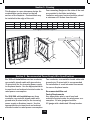
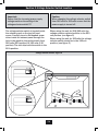
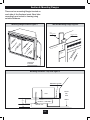
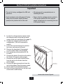
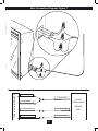
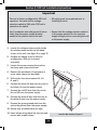
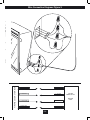
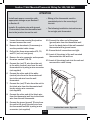
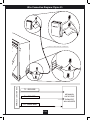
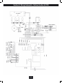
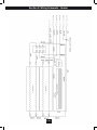
BUILT IN ELECTRIC FIREPLACE
INSTALLATION GUIDE
MODEL NUMBERS:
33EB304GRS
39EB364GRS
CONSUMER SAFETY INFORMATION
PLEASE READ THIS MANUAL BEFORE INSTALLING THIS APPLIANCE
WARNING
IF THE INFORMATION IN THIS MANUAL IS NOT FOLLOWED,
AN ELECTRIC SHOCK OR FIRE MAY RESULT CAUSING
PROPERTY DAMAGE, PERSONAL INJURY OR LOSS OF LIFE.
DO NOT STORE OR USE GASOLINE OR OTHER FLAMMABLE
VAPORS AND LIQUIDS IN THE VICINITY OF THIS
OR ANY OTHER APPLIANCE.
Thank you and congratulations on your purchase of a Classic Flame fireplace.
Please read the installation instructions before installing and operating
this appliance.
IMPORTANT: Read all instructions and warnings carefully before starting installation.
Failure to follow these instructions may result in a possible electric shock, fire
hazard and/or injury and will void the warranty.
For Customer Service:
E-Mail: [email protected]
In English Call: 866-661-1218
En Français Call: 866-374-9203
En Español Call: 866-611-1218
E-1
Twin-Star International, Inc.
Delray Beach, FL 33483
Made in China
Printed in China
LISTINGS AND CODE APPROVALS
THE BUILDERS BOX SERIES HAS BEEN TESTED AND APPROVED IN ACCORDANCE WITH THE
CSA xxxxxxx No.xxxxxxx STANDARDS FOR FIXED AND LOCATION
DEDICATED ELECTRIC ROOM HEATERS.
MODEL SPECIFICATIONS
MODEL
NUMBER
DESCRIPTION
33EB304AAS
33” STANDARD
39EB364AAS
39” STANDARD
VOLTAGE
RATED POWER
WATTS
REMOTE
CONTROL
AMPS
120/208/240
1440/2100/2700
YES
12.00/10.10/11.25
120/208/240
1440/2100/2700
YES
12.00/10.10/11.25
!!! WARNING !!!
THE INSTALLATION OF THE FIREPLACE UNIT MUST COMPLY WITH THE APPLICABLE
LOCAL AND/ OR NATIONAL ELECTRICAL CODES AND UTILITY REQUIREMENTS.
THIS INSTALLATION SHOULD BE ENTRUSTED TO DULY QUALIFIED
PERSONNEL WHERE REQUIRED BY LAW.
STEP - BY - STEP INSTALLATION OVERVIEW
(please read all instructions before installation)
and attach unit to frame using mounting
flanges provided ( see Section 3).
6) Wire a dedicated, properly fused circuit with
a 15 amp rating for the appropriate voltage
(120, 208/240). (See table above)
7) Install wall thermostat as outlined on
page 10 section E
8) Place all connections inside the junction
box. Secure the junction box cover on the
unit.
When installing a cable clamp make sure it
grips only the jacket of the service cable
and thermostat wire.
1) Rough in framing following the
recommended dimensions. (see figure 1)
2)Allow at least 8” of service cable for
connecting power supply wire to junction
box on fireplace insert when installing
before finishing wall. Allow up to 4 feet of
service cable for connecting power supply
wire to junction box on fireplace insert
after finishing wall.
3) Remove the outer jacket and strip the
individual conductors ½” from end.
4) Loosen the screw securing the junction
box cover and remove the cover.
5) Place unit in position in the framed opening, level with shims if necessary
!
!POWER SELECTION WARNING!
This unit is factory wired for 110 volt power supply.
If 208/240 volt operation is required, slide the voltage switch
and reconfigure the wiring accordingly (see figure 2).
Wires L1, L2, N & G are attached to the rear of
the junction box for easy access.
E-2
!
Section 1: Framing
Four mounting flanges on the sides of the unit
are provided to facilitate installation.
Insulation and vapor barrier should be placed
a minimum of 2 inches from the unit.
This fireplace is a zero clearance design. No
combustibles can be placed on the top
surface of the fireplace. Combustibles may
be installed to the edge of the unit.
MODEL
33EB304AAS
33EB364GRS
A
15.0”
16.0”
B
33.0”
39.0”
C
29”
33”
D
28.5”
32.7”
E
23.0”
27.2”
F
32.8”
38.7”
G
29.6”
36.0”
H
18.25”
22.0”
I
23.6”
27.6”
J
14.3”
15.3”
K
48.0”
55.0”
L
28.0”
34.0”
M
28.0”
34.0”
Framing Specifications: Figure 1
L
H
D
E
I
F
M
K
G
J
Section 2: Recommended Power Supply Wire Specifications
Two conductor, non-metallic sheath cable with
ground wire (3 wires total) is recommended
for installation of a wall mounted thermostat
for use on fireplace inserts.
For 120 volt installations use two conductor,
non-metallic sheath cable with ground wire
(3 wires total) for the incoming power supply
on fireplace inserts. Use the appropriate wire
to meet local and national electrical codes for
rated power consumption.
Recommended Wire and
Fusing Requirements
Use appropriate wire to meet local and
national electrical codes for rated power consumption. All wire gauges should be
12 gauge with a dedicated 15 amp breaker.
For 208/240 volt installations use three
conductor, non-metallic sheath cable with
ground wire (4 wires total) for the incoming
power supply on fireplace inserts. Use the
appropriate wire to meet local and national
electrical codes for rated power consumption.
E-3
Section 3: Voltage Selector Switch Location
Important:
Ensure that the incoming power supply
voltage matches the setting of the
voltage selector switch!!!!!!
Caution:
When changing the voltage selector switch
from 240 volts to 120 volts ensure that the
power supply is turned off.
The voltage selector switch is located inside
the exhaust panel on the top left hand
corner. Carefully insert a flat headed screwdriver inside the exhaust panel through the
hole in the mesh to change the switch from
240 volts (230 position) to 120 volts (115
position). The unit ships with the switch in the
115v position.
When wiring the unit for 208/240 volts the
voltage selector switch should be in the 230
volt position. (see figure 2)
When wiring the unit for 120 volts the voltage
selector switch should be in the 115 volt
position. (see figure 2)
115
230
Voltage Selector Switch: Figure 2
E-4
Section 4: Mounting Flanges
There are two mounting flanges located on
each side of the fireplace insert. Bend tabs
accordingly and mount to framing using
suitable hardware.
Wall and Mounting Flange: Figure 4
Mounting Flange Location: Figure 3
STUD
WOOD OR METAL
L
WAL
DRY
MOUNTING FLANGE
K
ROC
EET
/ SH
AMIC
CER
TILE
MOUNTING
FLANGES
Mounting Tolerances - Top View: Figure 5
MOUNTING FLANGE
STUD
9/16”
3/8”
DRYWALL / SHEETROCK
CERAMIC TILE
E-5
INSERT
TOP
VIEW
FRONT
Section 5: 120 Volt Installation Instructions
Important
• The unit is factory configured for 120 volt
operation.
• All wiring must be completed prior to
installing the unit.
• Use 2 conductor wire with ground (3 wires
total) from the power supply (breaker
panel) to the junction box on the unit.
• Ensure that the voltage selector switch is
in the proper position for the required
supply voltage prior to connecting the unit
to the power supply.
1. Locate the voltage selector switch inside the exhaust panel on the top left hand
corner of the unit. (see figure 2 on page 3)
2. Confirm the switch is set to 120 volt
configuration ( 115 volt is printed on switch).
3. Loosen the screw securing the junction
box cover and remove the cover.
4. Remove the knockouts (if necessary)
or use a cable clamp (not provided).
5. Pull out the four wires marked L1, L2,
N, and G.
6. Connect the black L1 wire from the unit to the black L1 from the power supply.
7. Connect the red L2 wire and the N wire
from the unit to the N wire from the
power supply.
8. Connect the green ground wire from the unit to the ground from the power supply.
9. Ensure that all connections are tight.
10. Insert all the wiring back into the unit and
secure with a cable clamp.
JUNCTION BOX
Junction Box Locator: Figure 6
E-6
Wire Connection Diagram: Figure 7
L1
L2
N
G
L1
L2
N
FIREPLACE -JUNCTION BOX
G
N - WHITE WIRE
N- WHITE WIRE
120 VOLT
POWER SUPPLY
L2 - RED WIRE
L1- BLACK WIRE
L1 - BLACK WIRE
G- GREEN WIRE
G - GREEN WIRE
E-7
BREAKER
PANEL
Section 6: 240 Volt Installation Instructions
Important
• The unit is factory configured for 120 volt
operation. You must set the voltage
selection switch to 240 volts (230 volt is
printed on the switch.
• All wiring must be completed prior to
installing the unit.
• Use 3 conductor wire with ground (4 wires
total) from the power supply (breaker
panel) to the junction box on the unit.
• Ensure that the voltage selector switch is
in the proper position for the required
supply voltage prior to connecting the unit
to the power supply.
1. Locate the voltage selector switch inside the exhaust panel on the top left hand
corner of the unit. (see figure 2 on page 3)
2. Confirm the switch is set to 240 volt
configuration (230 volt is printed
on switch).
3. Loosen the screw securing the junction
box cover and remove the cover.
4. Remove the knockouts (if necessary) or use a cable clamp (not provided).
5. Pull out the four wires marked L1, L2,
N, and G.
6. Connect the black L1 wire from the unit to the black L1 from the power supply.
7. Connect the red L2 wire from the unit to the red L2 from the power supply.
8. Connect the white N wire from the unit to
the white N wire from the power supply.
JUNCTION BOX
9. Connect the green ground wire from the
unit to the ground from the power supply.
10. Ensure that all connections are tight.
11. Insert all the wiring back into the unit and
secure with a cable clamp.
E-8
Junction Box Locator: Figure 8
Wire Connection Diagram: Figure 9
L1
L2
N
G
L1
L2
N
FIREPLACE -JUNCTION BOX
G
N - WHITE WIRE
N- WHITE WIRE
L2 - RED WIRE
L2 - RED WIRE
L1- BLACK WIRE
L1 - BLACK WIRE
G- GREEN WIRE
G - GREEN WIRE
E-9
240 VOLT
POWER SUPPLY
BREAKER
PANEL
Section 7: Wall Mounted Thermostat Wiring For 120/240 Volt
ATTENTION
• Install main power connection with
appropriate voltage as per Section C
or Section D.
• Wiring of the thermostat must be
completed prior to the mounting of
the unit.
• Install a 2 conductor wire with ground
(3 wires total) from the thermostat wall
box to the junction box on the unit.
• The following installation instructions are
for a single pole thermostat.
1. Loosen the screw securing the junction box and remove the cover.
10. Connect the other end of the green
(ground) wire from the thermostat wall box to the back plate of the wall mounted thermostat with a ground screw.
2. Remove the knockouts (if necessary) or use the provided cable clamp.
11. Ensure that all connections are tight.
3. Pull out the three wires marked T1, T2, and TG. (red, red, and green)
12. Insert all the wiring of the wall mounted 4. Remove the wire connector and separate thermostat into the wall box.
the wires marked T1 & T2.
13. Insert all the wiring back into the unit and secure with a cable clamp.
5. Connect the (red) T1 wire from the unit
to the white (neutral) wire from the wall thermostat box by using a wire connector. (not supplied)
6.
Connect the other end of the white
(neutral) wire from the thermostat wall box to the red wire from the wall
thermostat.
7. Connect the (red) T2 wire from the unit to the black wire from the thermostat wall box by using a wire connector.
(not supplied)
8. Connect the other end of the black wire from the thermostat wall box to the black wire from the wall thermostat.
9. Connect the green (ground) TG wire from the unit to the green (ground) wire from the thermostat wall box by using a wire connector. (not supplied)
E-10
JUNCTION BOX
Junction Box Locator: Figure 10
Wire Connection Diagram: Figure 11
E
IR
W
RED
K
AC
BL
RE
WI
CK
A
L
B
WH
E
WIR
ND
OU
GR
IT E
W IR
E
RE
WI
2 CONDUCTOR WIRE FROM WALL THERMOSTAT
T2
T1
TG
FIREPLACE -JUNCTION BOX
T2
T1
TG
T 2 - RED WIRE
MECHANICAL
LINE VOLTAGE
THERMOSTAT
WALL MOUNTED
T 1 - RED WIRE
T G - GREEN WIRE
E-11
Section 8: Wiring Schematic - Bottom Section & PCB
E-12
Section 9: Wiring Schematic - Heater
E-13
A Division of Twin-Star International, Inc.
115 S.E. 4th Avenue • Delray Beach, Florida 33483
Phone: 561-330-3201 • Fax: 561-330-3205
www.classicflame.com
E-14