1
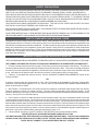
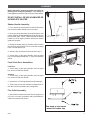
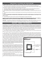
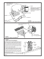
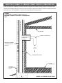
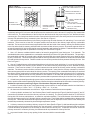
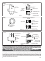
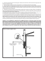
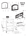
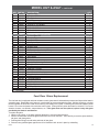
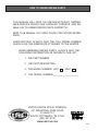
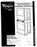
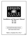
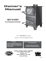
Owner’s
Manual
4027 & ASA7
Free-Standing Coal Heater
This is a COAL ONLY Room Heater
Tested to: UL 1482 and CAN/ULC S627-M93
STATES STO
TED
V
NI
USSC
COMPANY
USSC
E
U
CAUTION:
READ ALL INSTRUCTIONS CAREFULLY BEFORE STARTING THE
INSTALLATION OR OPERATING
THE HEATER
IMPROPER INSTALLATION MAY VOID
YOUR WARRANTY
DO NOT USE THIS HEATER
IN A MOBILE HOME OR TRAILER
UNITED STATES STOVE COMPANY
227 Industrial Park Road
P.O.Box 151
South Pittsburg, TN 37380
(423) 837-2100
C
R
US
851523
1
SAFETY PRECAUTIONS
PLEASE READ THIS ENTIRE MANUAL BEFORE YOU INSTALL AND USE YOUR NEW HEATING APPLIANCE. FAILURE TO FOLLOW INSTRUCTIONS MAY RESULT IN PROPERTY DAMAGE, BODILY INJURY, OR EVEN DEATH.
THIS HEATING APPLIANCE SHOULD BE INSTALLED ONLY BY AN EXPERIENCED COAL HEATER INSTALLER. IF
THIS HEATING APPLIANCE IS NOT PROPERLY INSTALLED, A HOUSE FIRE MAY RESULT. TO REDUCE THE RISK
OF FIRE, FOLLOW THE INSTALLATION INSTRUCTIONS. CONTACT LOCAL BUILDING OR FIRE OFFICIALS ABOUT
RESTRICTIONS AND INSTALLATION INSPECTION REQUIREMENTS IN YOUR AREA.
THIS HEATING APPLIANCE IS DESIGNED TO BURN COAL. THE USE OF ANY OTHER FUEL EXCEPT FOR COAL
IGNITION IS A VIOLATION OF FEDERAL LAW. BURN COAL ONLY.
INSTALL SMOKE DETECTORS IN YOUR HOME. EACH SMOKE DETECTOR SHOULD BE INSPECTED REGULARLY
AND KEPT IN GOOD WORKING CONDITION.
SAVE THESE INSTRUCTIONS. THESE INSTRUCTIONS SHOULD BE REVIEWED BY ALL FUTURE USERS OF THIS
HEATING APPLIANCE TO ENCOURAGE ITS PROPER OPERATION AND MAINTENANCE.
SAFETY STANDARDS AND BUILDING CODES
This appliance has been safety tested in accordance with UL safety standard 1482 by Warnock Hersey, a company in the
Quality Systems Division of Intertek Testing Services which is an international conformity assessment organization with
North American headquarters and offices worldwide. The Warnock Hersey listing mark on this appliance signifies that the
design and manufacturing of this appliance comply with Intertek Testing Services' comprehensive safety assessment
standards for solid fuel type room heaters. (There may be additional requirements to be met in order to comply with local
building codes or regulations. Before installing this appliance, check with building or fire officials to assure compliance with
local codes and regulations.)
MATERIALS NEEDED FOR PROPER INSTALLATION
THE FOLLOWING MATERIALS ARE NEEDED TO PROPERLY INSTALL THIS HEATER IN A RESIDENTIAL TYPE HOME.
THE CHIMNEY USED MUST BE CAPABLE OF PROVIDING A MINIMUM OF .06 INCHES WATER COLUMN DRAFT.
1. Chimney Connector (also known as stove pipe): The chimney connector joins the heater to the chimney. The chimney
connector pipes should be 6-inches in diameter 24-gauge minimum black steel. (Note: The number of 90 degree bends in
the chimney connector installation for appliances, such as this heater, which have a top exit flue collar should be restricted
to one. More than one 90 degree bend in the chimney connector could negatively affect chimney draft.)
2. Chimney: A code-approved masonry chimney. See the "MASONRY CHIMNEY REQUIREMENTS" portion of this
manual for details.
OR
A chimney complying with the requirements for Type 103-HT chimneys in the Standard for Chimneys, Factory Built,
Residential Type and Building Appliance, UL 103. See the "METAL PREFABRICATED CHIMNEY REQUIREMENTS"
portion of this manual for details.
3. Wall Thimble: A manufactured or site constructed device installed in combustible walls through which the chimney
connector passes to connect to a masonry chimney. The wall thimble is intended to keep walls from igniting. A wall
thimble is needed only if the chimney connector must pass through a combustible wall between the heater and the masonry
chimney. See Figure 5 for wall thimble options.
4. Floor Protector: If the floor on which the heater is to be installed is wood or any other combustible material , the heater
must be placed on a floor protector. The floor protector is to prevent the floor from catching fire from sparks or embers that
might escape the heater or drop from the joints of the chimney connector pipe. The floor protector must protect the floor
beneath and around the heater and chimney connector pipe as shown in Figure 9. The floor protector for this heater may be
larger than the floor protector shown in Figure 9 but it must not be smaller than the floor protector shown in Figure 9. The
floor protector must be a listed floor protector or a floor protector made of noncombustible inorganic material equal to or
better than 3/4-inch thick material having a thermal conductivity R value of 1.5.
5. Chimney Shield: See step 11 of the "TO INSTALL THE HEATER" portion of this manual for details.
THIS HEATER IS NOT APPROVED FOR MOBIL HOME INSTALLATION.
HOT WHILE IN OPERATION. KEEP CHILDREN, CLOTHING AND FURNITURE AWAY. CONTACT MAY CAUSE SKIN
BURNS. DO NOT USE CHEMICALS OR FLUIDS TO START THE FIRE. DO NOT BURN GARBAGE OR FLAMMABLE
FLUIDS. DO NOT CONNECT TO ANY AIR DISTRIBUTION DUCT SYSTEM.
2
USSC
ASSEMBLY
Before Assembly, inspect the heater thoroghly for
missing parts or shipping damage. If any damage or
missing parts are detected, report it to your heater dealer.
DO NOT INSTALL OR USE A DAMAGED OR
INCOMPLETE HEATER
Shaker Handle Assembly:
1. First, remove the two(2) bolts from the left side of the
unit where the shaker handle is to be mounted.
(A)
2. Next, spin the shaker plate (a) counteclockwise until
it stops. Slide the shaker handle through the hole and on
to the shaker grate. NOTE: Make sure that the shaker
handle is in a 90 degree position and that the shaker
grates are lying flat.
3. Rotate the shaker plate (a) clockwise until it touches
the unit.Then give it another 1/2 turn or until the mounting
holes coincide with the unit.
4. Attach to the unit with the bolts removed in step 1.
5. Screw one(1) of the spring handles, from the parts
box, on to the shaker handle 3/4” -1” down in a clockwise
motion.
Feed & Ash Door Assemblies:
Feed Door1. Screw one(1) of the spring handles, from the parts
box, on to the Feed Door handle.
Ash Door1. Screw one(1) of the spring handles, from the parts
box, on to the Feed Door handle.
2. Insert the 2-1/2” Carriage Bolt into the spin damper.
3. Then screw it in into the Ash Door as shown and Attach the Lock Nut provided to the Carriage Bolt.
Flue Collar Assembly:
1. Mount the flue collar to the top of the unit using the (3)
5/16-18 x 1-1/2 bolts, (3) washers, and (3) weld tabs provided in the parts box as shown
Side view of flue collar
mount to heater top
USSC
3
SELECTING A LOCATION FOR YOUR HEATER
1. When locating the heater , consider safety, convenience, traffic flow, and the fact that the heater will need a
chimney,chimney connector,and possibly a floor protector. Make sure none of these materials will be obstructed.
2. The heater should be located away from door ways and central heat outlets to reduce the chances of drafts, blowing
smoke, ashes or sparks out of the heater during refueling or ash removal.
3. The heater should be located in an open area to allow for necessary clearances as specified within this manual.
4. Keep furniture, drapes, curtains, wood, paper and other combustibles far away from the heater.
5. Never install the heater in locations where gasoline, kerosene, charcoal lighter, or any other flammable liquids are
stored
6. The heater should be located where a small supply of wood may be kept conveniently close but not within 36-inches of
the heater.
7. The heater should not be located beneath overhanging shelves, low ceilings or other structures or elevated so that less
clearance is created above the heater than is provided when the heater is normally installed in a room with a 7 foot
minimum ceiling.
8. Be sure the chimney will be at least 10 feet from flammable gas or liquid storage tanks.
DANGER: DO NOT CONNECT THIS HEATER TO A CHIMNEY FLUE SERVING ANOTHER APPLIANCE. THERE IS A
SERIOUS SAFETY RISK IF TWO APPLIANCES ARE CONNECTED TO THE SAME CHIMNEY FLUE.
CAUTION: The operation of exhuast fans such as bath room fans, attic fans, etc. might starve the heater of combustible
air creating a negative pressure in the room. Provide adequate ventilation in the room occompaning the heater.
MASONRY CHIMNEY REQUIREMENTS
If the heater is to be connected to a masonry chimney, the heater should not be installed until it is determined that the
chimney is safe for use. Before installing the heater, have the chimney inspected by a building inspector, fire department,
or qualified heating engineer. To prevent risk of walls, roof, or other combustibles catching fire from the extremely hot fire,
smoke, and flue gases, and to obtain a proper draw, a chimney must meet the minimum standards for masonry chimneys
established by the National Fire Protection Association (NFPA). Make certain the inspection agency is familiar with NFPA
No. 211 and all local codes. Some of those minimum standards are listed here for your convenience.
1. The chimney must not be obstructed or clogged. An obstructed or clogged chimney could cause smoke and the
dangerous carbon monoxide in smoke to spill back into your home.
2. Your masonry chimney must be supported on an adequate foundation and must have either a 5/8" thick fireclay or
stainless steel lining. There must be at least 1/2-inch air space between the flue liner and the chimney wall. (See Figure 1.)
3. A chimney inside the house must have at least 2 inches of clearance to the combustible structure. A chimney outside
the house must have at least 1 inch clearance to the combustible structure. Fire stops must be installed at the spaces
where the chimney passes through floors and/or ceilings. (See Figure 2.) Insulation should be at least 2 inches from the
chimney to leave an air space around the chimney. (See Figure 3.)
FIGURE 1 4. The flue lining of a masonry chimney must be smooth and
MASONRY CHIMNEY
have no leaks. The inside of the chimney flue liner should be no
REQUIREMENTS
smaller than 8 inches square or 6 inches round; a smaller chimney flue liner will be too restrictive to the flow of smoke and
gases. A 6 inch diameter round liner is preferred because round
flues draw better than square flues.
5. Since an oversized chimney flue contributes to the accumulation of creosote, the size of the chimney flue liner must be
checked to determine that it is not too large for the heater. For
this heater, the inside cross-sectional area of the chimney should
be no more than 85 square inches to assure proper venting.
6. The top of the chimney must be at least 3 feet above the
point where it comes through the roof, and at least 2 feet higher
than any obstruction within a 10 foot radius.(See Figure 4.)
7. If the heater has insufficient draft, the draft may be improved
by extending the height of the chimney.
FLUE
MINIMUM 1/2" AIR SPACE
5/8" FIRECLAY OR
STAINLESS STEAL
FLUE LINER
CHIMNEY WALL 4"
NOMINAL
FOUNDATION
8. Make certain the chimney is kept clean and it is not blocked.
Check for limbs overhanging the top of the chimney periodically.
4
USSC
NONCOMBUSTIBLE
FIRE-STOPPING
MATERIAL
FLOOR
MINMUM 2 INCH CLEARANCE
FOR INTERIOR CHIMNEY.
MINIMUM 1 INCH CLEARANCE
FOR EXTERIOR CHIMNEY TO
SHEATHING
CEILING
CHIMNEY
CAULKING
FLOOR
(SECOND STORY)
FIGURE 2MASONRY CHIMNEY REQUIREMENTS
Minimum 2 Inch Clearance
From Combustible Material
and Insulation
Ce
ilin
g
Noncombustible
Fire-Stopping Material
FIGURE 3MASONRY CHIMNEY REQUIREMENTS
FIGURE 4CHIMNEY HEIGHT REQUIREMENTS
A Chimney must be the required height above the roof
or other obstruction for safety and for proper draft operation. The requirement is that the chimney must be at
least 3 feet higher than the highest point where it passes
through the roof and at least 2 feet higher than the highest part of the roof or structure that is within 10 feet of
the chimney, measured horizontally.
The above chimney heights are the minimum required
by codes for safety purposes to allow sparks existing in
chimney time to cool before they land on the roof. Additional height will generally increase draft, improve heater
operating characteristics and reduce back drafting and
puffing problems due to wind
A masonry chimney is shown above. However, height
requirements are the same for a metal prefabricated
chimney.
USSC
AT LEAST
3 FEET
AT LEAST
3 FEET
10 FEET
5
CONNECTION OF CHIMNEY TO A MASONRY CHIMNEY THROUGH A COMBUSTIBLE WALL
Figure 5 shows how to connect the chimney connector of a heater to a masonry chimney through a combustible wall.
There are five allowable ways that a chimney connector can be connected to a masonry chimney by passing through a
combustible wall. NFPA Standard 211 allows the following wall pass-through systems.
LINED CHIMNEY FLUE
FIGURE 5 CONNECTION OF CHIMNEY CONNECTOR TO A
MASONRY CHIMNEY THROUGH A COMBUSTIBLE
WALL
CEILING
SEE PARTS A, B, C,
D, AND E OF THIS
FIGURE FOR
OPTIONS.
CHIMNEY CONNECTOR
MASONRY CHIMNEY
CONSTRUCTED TO
NFPA 211
TO
HEATER
COMBUSTIBLE WALL
FLOOR
PROTECTOR
AIRTIGHT
CLEANOUT
DOOR
(FIGURE 5 CONTINUED ON NEXT PAGE)
6
USSC
MINIMUM CHIMNEY CLEARANCE TO
BRICK AND COMBUSTIBLES IS 2 IN.
MINIMUM 12 IN.
TO COMBUSTIBLES
CHIMNEY FLUE
PART A, FIGURE 5
(FIGURE 5 CONTIUED ON NEXT PAGE)
MASONRY CHIMNEY
CONSTRUCTED TO
NFPA 211
MINIMUM CLEARANCES 12
IN. OF BRICK ALL AROUND
CHINEY CONNECTOR TO
HEATER
FIRE CLAY LINER
(5/8" MIN. WALL THICKNESS)
MIN. 3-1/2" THICK BRICK
MASONRY WALL
1. Use a minimum 3-1/2" thick brick masonry wall framed into the combustible wall. A fireclay liner (ASTM C315 or
equivalent) having a 5/8" minimum wall thickness must be used and it must be at least 12" away from any material that
could catch fire. The inside diameter of the fireclay liner shall be sized for the proper snug fit of a 6" diameter chimney
connector pipe. The fireclay liner shall run from the outer surface of the brick wall to, but not beyond, the inner surface of the
chimney flue and shall be firmly cemented in place. See Part A of Figure 5.
2. Use a solid insulated listed factory-built chimney length having an inside diameter of 6" and having 1" or more of solid
insulation. There must be at least a 9" air space between the outer wall of the chimney length and any combustible
materials. The inner end of the chimney length shall be flush with the inside of the masonry chimney flue shall be sealed
to the flue and to the brick masonry penetration with nonwater-soluble refractory cement. Sheet steel supports which are
at least 24 gauge(0.024") in thickness shall be securely fastened to wall surfaces on all sides. Fasteners between supports
and the chimney length shall not penetrate the chimney liner. See Part B of Figure 5.
3. Use a 10" diameter ventilated thimble made of at least 24 gauge(0.024") steel having two 1" air channels. The
ventilated thimble must be separated from combustible materials by a minimum of 6" glass fiber insulation. The opening in
the combustible wall shall be covered and the thimble supported with sheet steel supports which are at least 24 gauge
(0.024") in thickness. The sheet steel supports shall be securely fastened to wall surfaces on all sides and shall be sized
to fit and hold the chimney section. Fasteners used to secure chimney sections shall not penetrate chimney flue liner. See
Part C of Figure 5.
4. Use an 8" inside diameter solid insulated listed factory-built chimney length which has 1" or more of solid insulation.
The minimum length of this chimney section shall be 12" and will serve as a pass-through for the 6" diameter chimney
connector. There must be at least a 12" air space between the outer wall of the chimney section and any combustible
materials. The chimney section shall be concentric with and spaced 1" away from the chimney connector by means of
sheet steel support plates on both ends of the chimney section. The opening in the combustible wall shall be covered and
the chimney section supported on both sides with sheet steel supports which are at least 24 gauge (0.024") in thickness.
The sheet steel supports shall be securely fastened to wall surfaces on all sides and shall be sized to fit and hold the
chimney section. Fasteners used to secure chimney sections shall not penetrate chimney flue liner.See Part C of Figure 5.
5. A listed factory-built wall pass-through system may be purchased and installed according to the instructions packaged
with it to provide a safe method of passing the chimney connector through a combustible wall for connection to a masonry chimney.
Additional requirements pertaining to Figure 5 and the above wall pass-through systems:
1. Insulation material used as part of wall pass-through system shall be of noncombustible material and shall have a
thermal conductivity of 1.0 Btu • in./ft.² • °F (4.88 kg • cal/hr • m² • °C) or less
2. All clearances and thicknesses are minimums: larger clearances and thickness are acceptable.
3. A chimney thimble, as shown for 3" and 4" above (Parts C and D respectively of Figure 5) shall be for types "3" and "4"
connections to facilitate removal of the chimney connector for cleaning. The chimney thimble shall be of ASTM C315
fireclay with 5/8" minimum wall thickness , or material or equivalent durability. The inside diameter of the thimble shall be
sized for the proper snug fit of a 6" diameter chimney connector pipe. The thimble shall be installed without damage to the
chimney flue. The thimble shall extend through the chimney wall to, but not beyond, the inner surface of the chimney flue
and shall be permanently cemented in place with high temperature cement.
4. A chimney connector to a masonry chimney, except for 2" above (Part B of Figure 5), shall extend through the wall pass
-through system to the inner face of the chimney flue, but not beyond. It does not have to be fastened in place so long as
it cannot accidently be pulled out of the chimney or shoved into the chimney flue. If fasteners are used to secure the
chimney connector to a masonry chimney, the fasteners shall not penetrate the chimney flue liner.
5. Any material used to close up any opening for the connector shall be noncombustible.
USSC
7
NONSOLUBLE
REFACTORY
CEMENT
CHIMNEY LENGHT
FLUSH WITH INSIDE
OF FLUE
AIR SPACE
9 IN. MINIMUM
AIR SPACE
FACTORY-BUILT
CHIMNEY LENGHT
CHIMNEY FLUE
MINIMUM CHIMNEY CLEARANCES FROM MASONRY TO
SHEET STEEL SUPPORTS AND COMBUSTIBLES 2 IN.
PART B
FIGURE 5 (FIGURE 5 CONTINUED)
MINIMUM CLEARANCE
9 IN. ALL AROUND
CHIMNEY CONNECTOR
TO HEATER
USE CHIMNEY MFRS. PARTS TO
ATTACH CONNECTOR SECURELY
SOLID INSULATED, LISTED
FACTORY-BUILT CHIMNEY LENGHT
MASONRY CHIMNEY CONSTRUCTED
TO NFPA 211
PART C
FIGURE 5
SHEET STEEL SUPPORTS
(24 GAUGE MIN. THICKNESS)
MINIMUM CHIMNEY CLEARANCES FROM MASONRY TO
SHEET STEEL SUPPORTS AND COMBUSTIBLES 2 IN.
24 GAUGE
VENTILATED THIMBLE WITH
TWO 1 INCH AIR CHANNELS
CHIMNEY FLUE
CHIMNEY THIMBLE
TWO VENTILATED AIR
CHANNELS EACH 1 INCH.
CONSTRUCED OF
SHEET STEEL.
MASONRY CHIMNEY CONSTRUCTED
TO NFPA 211
CHIMNEY CONNECTOR
TO HEATER
MINIMUM 6 IN. GLASS
FIBER INSULATION ALL AROUND
SHEET STEEL SUPPORTS
(24 GAUGE MIN. THICKNESS)
MINIMUM CHIMNEY CLEARANCES FROM MASONRY TO
SHEET STEEL SUPPORTS AND COMBUSTIBLES 2 IN.
PART D
FIGURE 5
SHEET STEEL SUPPORTS
MINIMUM CLEARANCE
2 IN. ALL AROUND
CHIMNEY SECTION
1 IN. AIR SPACE TO
CHIMNEY LENGHT
CHIMNEY
CONNECTOR
AIR SPACE
2 IN.
CHIMNEY FLUE
CHIMNEY THIMBLE
MASONRY CHIMNEY CONSTRUCTED
TO NFPA 211
CHIMNEY CONNECTOR
TO HEATER
SOLID INSULATED, LISTED
FACTORY-BUILT CHIMNEY
LENGHT (12 IN. LONG MIN.)
SHEET STEEL SUPPORTS
(24 GAUGE MIN. THICKNESS)
PART E - (Figure 5)
In addition to the methods shown by A, B, C, and D of Figure 5, a listed factory-built wall pass-through system may
be purchased and installed according to the instructions packaged with it to provide a safe method of passing
chimney connector through a combustible wall for a connection to a masonry chimney.
CONNECTION OF CHIMNEY CONNECTOR TO A MASONRY CHIMNEY WHEN CHINEY CONNECTOR
DOES NOT PASS THROUGH A COMBUSTIBLE WALL
If the chimney connector does not have to pass through a combustible wall to get to a masonry chimney, simply connect
the chimney connector directly to the masonry chimney's chimney thimble as described and shown by parts C and D of
Figure 5. Remember, the chimney connector should extend into the chimney thimble to the innerface of the chimney flue
but not beyond; if the chimnney connector is extended through the chimney thimble into the chimney flue, resistance to the
flow of smoke and gases up the chimney will occur; that flow resistance will have an adverse affect on the operation and
performance of the heater and venting system.
8
USSC
METAL PREFABRICATED CHIMNEY REQUIREMENTS
Any metal prefabricated chimney that this heater is connected to must be a Listed High Temperature Type 103-HT FactoryBuilt Residential Type and Building Heating Appliance Chimney. Its interior size should be no smaller than 6 inches in
diameter or no larger than 8 inches in diameter. An undersized chimney (less than 6 inches interior diameter) will result in
poor draft and insufficient operation where as an oversized chimney (larger than 8 inches diameter) will result in poor draft
and more creosote accumulation.
When a metal prefabricated chimney is used, the manufacturer's installation instructions must be followed precisely. You
must also purchase (from the same manufacturer) and install the ceiling support package or wall pass-through and "T"
section package, firestops (when needed), insulation shield, roof flashing, storm collar, and chimney cap (with a spark
arrester if desired or where required by code). NOTE: IF THE HEATER IS BEING INSTALLED IN A MOBILE HOME, A
SPARK ARRESTER IS REQUIRED BY CODE TO BE INSTALLED WITH THE CHIMNEY CAP.
The top of the chimney should be at least three feet above the point where it comes through the roof and at least to feet
higher than any part of the roof or house within a ten foot radius. See Figure4.
A straight up chimney is best because it will draw better.
When ordering a metal prefabricated chimney, specify the type home (residential or mobile) in which the chimney will be
installed, and the method of installation which is being planned.
METAL PREFABRICATED CHIMNEY INSTALLATION
There are basically two methods of metal prefabricated chimney installation. One method is to install the chimney inside
the residence through the ceiling and the roof. The other method is to install an exterior chimney that runs up the outside
of the residence.
Figure 6 shows a metal prefabricated chimney installed inside the residence through the ceiling and roof.
Figure 7 shows an exteriorly installed metal prefabricated chimney that runs up the outside of the residence.
The components illustrated by Figures 6 and 7 may not look exactly like the system you purchased, but they demonstrate
the basic components for a proper and safe installation.
REMEMBER: Follow the chimney manufacturer's installation instructions and maintain the manufacturer's specified clearance distance.
THE CHIMNEY CONNECTOR SHALL NOT PASS THROUGH AN ATTIC, ROOF SPACE, CLOSET FLOOR CEILING, OR
SIMILAR CONCEALED SPACE. WHERE PASSAGE THROUGH A WALL OR PARTITION OF COMBUSTIBLE CONSTRUCTION IS DESIRED, THE INSTALLATION MUST CONFORM WITH CAN/CSA-B365.
USSC
9
FIGURE 5 METAL PREFABRICATED CHIMNEY INSTALLED INSIDE THE RESIDENCE THROUGH THE
CEILING AND THE ROOF
LISTED CHIMNEY
INSTALL AN INSULATION SHEILD
TO MAINTAIN THE SPECIFIED
CLEARANCE TO INSULATIO. INSULATION IN THIS AIR SPACE WILL
CAUSE A HEAT BUILDUP WHICH
MAY IGNITE THE CEILING JOIST.
INSULATION
SHEILD
COMBUSTIBLE
CEILING
JOIST
SPECIFIED
CLEARANCE
CEILING
SUPPORT
CHIMNEY
CONNECTOR
TO HEATER
DETAIL OF
CONNECTION
CHIMNEY CAP (WITH SPARK
ARRESTER IF DESIRED OR
WHERE REQUIRED BY LAW.)
MAINTAIN 2 INCH
CLEARANCE
STORM COLLAR
ROOF
FLASHING
LISTED CHIMNEY
CEILING
CEILING SUPPORT
CHIMNEY CONNECTOR
TO
HEATER
WALL
FLOOR PROTECTOR
10
USSC
FIGURE 7 EXTERIORLY INSTALLED METAL PREFABRICATED CHIMNEY THAT RUNS UP THE OUTSIDE OF THE
RESIDENCE.
COMBUSTIBLE OUTSIDE
WALL
2" CLEARANCE
(BETWEEN WALL
AND CHIMNEY)
SECTION LISTED
CHIMNEY PIPE
TO HEATER
CHIMNEY
CONNECTOR
TRIM COLLAR
ON INSIDE WALL
LISTED CHIMNEY
INSULATED "T"
WALL SUPPORT
WALL SPACER
ON OUTSIDE WALL
DETAIL OF
CONNECTION
STORM COLLAR
CHIMNEY CAP
(WITH SPARK ARRESTER
IF DESIRED OR WHERE
REQUIRED BY LAW.)
MAINTAIN 2 INCH CLEARANCE THROUGH EAVE
ROOF FLASHING
CEILING
CHIMNEY
CONNECTOR
INSULATED "T"
TO
HEATER
FLOOR
PROTECTOR
WALL
USSC
11
HEATER INSTALLATION
CAUTION: FOR YOUR SAFETY, THE INSTALLATION OF THIS HEATER MUST COMPLY WITH LOCAL CODES AND
REGULATIONS. CONTACT LOCAL BUILDING OR FIRE OFFICIALS ABOUT INSPECTION TO ASSURE PROPER
COMPLIANCE WITH LOCAL CODES AND REGULATIONS.
MINIMUM CLEARANCES TO COMBUSTIBLE WALL AND CEILINGS
CAUTION: MOST WALLS AND CEILINGS CONTAIN WOOD EVEN THOUGH THEY ARE MADE OF SHEETROCK OR
PLASTER ON THE OUTSIDE. THESE WALLS AND CEILINGS CAN CATCH FIRE FROMTHE HOT WATER HEATER OR
CHIMNEY CONNECTOR IF HEATER AND CHIMNEY CONNECTOR ARE NOT PROPERLY INSTALLED.
Minimum clearances to unprotected combustible walls and ceilings as noted by Figure 8 must be maintained. Drapes,
curtains, furniture and other combustible materials should be kept much further away from the heater chimney connector
to avoid a fire.
CEILING
CEILING
21
21
17
21
32
SIDE WALL
BACK WALL
17
BACK WALL
BACK WALL
32
WALL
32
32
FIGURE 8 MINIMUM CLEARANCES TO COMBUSTIBLE MATERIALS (IN INCHES)
CORNER
INSTALLATION
f you choose to, you may install the heater and chimney connector closer to combustible surfaces than indicated by Figures
2 through 4 IF a clearance reduction system is also installed to protect combustible ceilings and walls near the heater and
chimney connector. However, there are limits to how close the heater and chimney connector can be installed to combustible
surfaces protected by a clearance reduction system.
A correctly installed clearance reduction system protects the combustible surfaces well beyond the sides and above the
top of the heater and beyond the sides and top of the chimney connector pipe.
Two common types of clearance reduction systems use sheet metal with a minimum thickness of 28 gauge (galvanized steel,
aluminum, copper) or a 3-1/2 inch (4 inch nominal) thick masonry wall. Either of these materials must be spaced out 1 inch
from the combustible surfaces. With sheet metal, non-combustible spacers are used to maintain the 1 inch air space. With
a masonry wall, metal wall ties and furring strips, if needed are used to anchor the brick to the wall. To avoid excessive heat
transmission, the spacers or wall ties should not be placed directly behind the heater or chimney connector. The 1 inch air
space provides free air circulation. It is essential that there be openings at the top and bottom of these clearance reducers
so cool air can enter at the bottom and hot air exit at the top. It is the "chimney effect" whereby when the air in the space
is heated, it rises exiting from the top and being replaced by cooler air at the bottom, that makes these shields effective.
12
USSC
Masonry, or other non-combustible products, attached directly to a combustible surface without an air space offer very little
protection and cannot be considered a clearance reducer unless specified materials have been tested and listed for direct
attachment to a combustible surface. The same applies to thin veneer brick and stone coverings. These materials provide
adequate protection only when mounted on sheet metal with a 1 inch spacing to the wall.
A variety or prefabricated clearance reduction systems which have been tested and listed are available through heater
dealers. Always look for a safety listing label on the product when selecting a clearance reduction system and make sure
it is designed for solid fuel appliances. The manufactures of these systems provide specific installation instructions that
must be followed exactly for a safe installation.
Should you choose to make your own clearance reduction system, contact your local fire department, fire marshal or building
code inspector for specific requirements regarding home constructed clearance reduction systems and safe installation
clearances to protect combustible materials.
CAUTION: READ ALL INSTRUCTIONS BEFORE INSTALLING THE HEATER.
TO INSTALL THE HEATER:
1. Make ready a suitable chimney. The chimney must complywith the requirements for Type 103-HT chimneys in the
standard for chimneys, Factory Built, Residential Type and Building Appliances, UL 103.
2. Gather the necessary materials, tools, and supplies which will be needed to install the heater.
CAUTION: DO NOT USE MORE THAN ONE 90 DEGREE BEND (ELBOW) IN THE CHIMNEY CONNECTOR
INSTALLATION. MORE THAN ONE 90 DEGREE BEND (ELBOW) IN THE CHIMNEY CONNECTOR COULD NEGATIVELY AFFECT CHIMNEY DRAFT.
3. I f the floor on which the heater is to be installed is wood or any other combustible material, place a floor protector (described
earlier) on the floor where the heater will be installed.
CAUTION: THE FLOOR PROTECTOR MUST NOT BE PLACED ON CARPET. REMOVE CARPET FROM BENEATH
THE FLOOR PROTECTOR.
4. Place the heater on the floor protector as shown in Figure 9.
5. Assemble the chimney connector stove pipe from the heater's flue collar to the chimney to determine if the chimney
connector pipe will correctly extend from the heater's flue collar to the chimney. Any horizontal section of chimney connector
stove pipe must slope upward at least 1/4-inch rise to the horizontal foot to help maintain a sufficient draft. Always install
the chimney connector pipe with the crimped end toward the heater to prevent creosote or soot from leaking out of the chimney
connector pipe joints. MAKE SURE CLEARANCES TO COMBUSTIBLES ARE MAITAINED AS SPECIFIED BY FIGURE
8 IF A CLEARANCE REDUCTION SYSTEM IS NOT INSTALLED.
FIGURE 9 PLAN VIEWS SHOWING FLOOR PROTECTOR'S MINIMUM SIZE (DIMENSIONS IN INCHES)
2
2
8
FLOOR PROTECTOR
FLOOR PROTECTOR
8
16
8
8
WHEN CHIMNEY CONNECTOR EXITS
THROUGH THE CEILING
USSC
16
8
8
WHEN CHIMNEY CONNECTOR EXITS
THROUGH THE WALL
13
6. Place the crimped end of the first chimney pipe or elbow into the heater's flue collar and mark it through each of the
holes in the heater's flue collar.
7. Remove the pipe or elbow from the flue collar and drill 1/8 - inch diameter holes at the points marked.
8. Apply the furnace to the inside surface of the heater's flue collar, reinstall the first pipe or elbow and fasten in place with
No. 8 sheet metal screws. Apply additional furnace cement to the outside of the chimney connector flue collar joint if an
airtight seal was achieved when the pipe or elbow was installed. Wipe all excess furnace cement from the joint with a rag
or paper towel before the cement dries.
9. Assemble the remaining chimney connector pipes by apply furnace cement to the joints, drilling 1/8-inch diameter
holes for and attaching each joint with three(3) No. 8 sheet metal screws. Wipe all excess furnace cement from the joints
with a rag or a paper towel before the cement dries.
10. Depending on the type chimney installed, connect the chimney connector to the chimney as shown in Figure 5 or as
described by the chimney's manufacturer. Remember , we highly recommend use of UL 103-HT chimney.
11. If the chimney to which the heater is connected is a metal prefabricated chimney that exits the home at a point 7 feet
or less above ground level and runs up the outside of the residence, it will be necessary to construct a chimney shield to
prevent someone from coming in contact with the outer surface of the hot chimney while the heater is in operation. The
shield should be constructed from wire mesh or expanded metal (22 gauge minimum) to allow air circulation around the
chimney. The openings in the shield should not be large enough to allow a 1/2-inch diameter rod to pass through. The shield
should have sufficient rigidity to provide the required protection and be permanently installed as shown in Figure 10.
DANGER: IF ANY CLEARANCE TO UNPROTECTED COMBUSTIBLE WALL OR CEILING IS LESS THAN THOSE
SPECIFIED BY FIGURE 8 AFTER HEATER INSTALLATION IS COMPLETED, A CLEARANCE REDUCTION SYSTEM
MUST BE INSTALLED BEFORE THE FIRST FIRE IS BUILT IN THE HEATER; OTHERWISE, THE UNPROTECTED
WALL OR CEILING COULD CATCH FIRE. REMEMBER, THERE ARE ALSO LIMITS AS TO HOW CLOSE THE HEATER
CAN BE INSTALLED TO A COMBUSTIBLE SURFACE PROTECTED BY A CLEARANCE REDUCTION SYSTEM. REREAD "MINIMUM CLEARANCES TO COMBUSTIBLE WALL AND CEILINGS" PRESENTED EARLIER IN THIS MANUAL.
FIGURE 10 INSTALLATION OF CHIMNEY SHIELD
7 FEET
(SHIELD NOT REQUIRED
BEYOND 7 FEET ABOVE
GROUND LEVEL.)
CHIMNEY
SHIELD
GROUND LEVEL
14
USSC
OPERATING INSTRUCTIONS
Burning Coal in your 4027/ASA7
Your Wondercoal is capable of burning both bituminous and Anthracite coal. Anthracite is the best coal fuel because its long even burn time, high
heat output, and cleanliness make it a good choice for the home. However, keep in mind it is a much more difficult fuel to use and requires more care
and patience.
SIZE OF COAL: Most sizes of bituminous coal will work in your heater; for best results we recommend large nut coal to small egg coal (1-3/4" diameter
to 4" diameter). When burning anthracite, use egg or broken with sizes between 2-5/16" and 4-3/8". Note that it is important to the life of your stove
to buy coal which has been sized and cleaned. Cleaning insures removal of rocks and other materials.
STOVE OPERATION: All coal fires should be started with wood which will allow the fire to get hot enough to ignited the coal. The Best ignition fires
utilize dry pine or other resinous soft woods as kindling, with hard wood (oak, hickory, ash) added to increase the heat prior to adding the coal.
BITUMINOUS: Once your kindling and wood fire has produced a bed of well established coals start adding coal in layers allowing each to ignite before
adding more. Bituminous has a high volatile content and, as a result, should be fired with the "conical method" - with the highest portion of your firebed
in the center of the firebox. The first flames will be long and generally orange or yellow and produce quite a bit of smoke. As the gases burn off the
flames become shorter, change color and produce less smoke.
Once the fire is WELL ESTABLISHED add coal to the center of the firebox forming the cone. Burning in this fashion allows heat to drive off the volatile
gases, and turbulence created increases the burn efficiency. You will have to experiment with your particular setup as no two chimney's and installations
are going to be the same. Just remember to allow enough secondary air to enter and keep your stove pipe damper open so that volatiles are properly
burned. Before refueling, take the time to break up the cone a little with a poker, especially if it has caked over or formed a crust. But, be careful
not to mix the coal as this increases the chances of forming clinkers. When shaking the grate be gentle. Just a few short movements - front to rear
- are beter than a lot of agitation. The objective is to remove a small amount of the ashes without disturbing the fire. Stop when you see a glow in
the ashes or the first red coals fall into the ash pan. Excessive shaking wastes fuel and can expose the grate to very high temperatures which can
cause warpage or burnout.
For overnight operation (long duration burn time) shake the fire and add coal, retaining your center cone. Once the volatiles are burned off close
the feed door and adjust your stove pipe damper. Then adjust your thermostat to the desired heat level.
You will have more MAINTENANCE with bituminous than with anthracite coal as more soot will collect on heating surfaces and in pipes, requiring more
frequent cleaning.
ANTHRACITE: Before starting the fire open the stove pipe damper, turn the automatic thermostat to high, open the ash pit door and feed door, place
newspaper and finely split kindling on the grate, light the paper, add larger hard wood after the kindling is burning brightly. CAUTION: Never use gasoline,
lantern fuel, kerosene, charcoal lighter fluid, or other flammable liquids to start or freshen up a fire in this heater. Place the larger pieces
of wood on the fire so that are slightly separated and form a level for the addition of coal. It will take 10 to 20 minutes before this wood is thoroughly
ignited. Adding coal too soon will cut the air supply and smother the fire.
Add a thin layer of coal (perferably smaller chunks) to the wood fire, being careful not to disturb it too much or cut off the draft. Then, add a second
heavier layer after the coal is ignited and burning well. If necessary, add a third layer to bring the coal up to the top of the front brick (not above!).
Be sure you have closed your ash door.
Before adding further fuel, be sure you leave a red spot of glowing coals in the center of the firebox to insure that you have not smothered the fire
and to help ignite the gases given off by the new charge. A deep charge will give a more heat and a longer fire but it may take one to two hours before
the whole bed is fully ignited.
When the fire is well established and the room is becoming warm, partially close the dampers. You will have to experiment with your particular setting
of all dampers and controls as your chimney provides the draft necessary to not only exhaust the smoke, but to pull combustion air into the heater
as well - and no two chimney's perform the same. Under ideal draft conditions you should be able to turn the secondary air supply on the feed door
to a near closed position - but leave the ash pit damper at least partially open to prevent the fire from going out. Adjust the stove pipe damper to reduce
the draft on the fire. With anthracite you will see short blue flames above the coal, except when the fire is started or a new charge is added. If, however,
there is no flame then the fire needs more air from the bottom (unless it is near the end of its burn cycle and needs to be recharged).
Only when the coal is burned down to half its original depth it is time to add fresh coal. When doing so, open your stove pipe damper and turn your
thermostat damper to high, which will allow the fire to burn off any accumulated gases. Open the feed door, and with a small rake, hoe or hooked
poker pull the glowing coals to the front of the firebox. Try not to disturb the fire too much. Next, add a fresh charge to the back being careful not
to seal off the top. Close the feed door but leave the spin damper (Fig. 9) open for a few minutes until the until the volatile gases have burned off.
It is not necessary to shake down the ashes each time you refuel your Wondercoal. Experience will be your best teacher.
BANKING THE FIRE: For extended operation, such as overnight, you will need to bank the fire. To do so heap coal up along the sides and back
of the firebox so that the fire gradually burns it over a longer period of time. You will also reduce the intensity of the fire without letting it go out. Follow
the same procedure as for refueling. If possible, avoid shaking, as a heavier layer of ash will help reduce the intensity of the fire during this time. After
loading let the fire establish itself for about 30 minutes. Then close your damper and automatic control to the point where the house does not become
too cold. It is important that you begin banking early enough before retiring or leaving that you can make necessary adjustments after the fire is well
established.
To revive a coal fire that is almost out, you should (1) open the ash door and stove pipe damper and close the spin damper (Fig. 9) on the door to
get a good enough draft through the grate. (2) Place a thin layer of dry coals over the entire top of the fire. DO NOT POKE OR SHAKE THE FIRE
AT THIS TIME! (3) After the fresh coal has become well ignited shake the grate (just a little) and you will be ready to refuel.
DO NOT burn coke, charcoal, high volatile bituminous coal, sub bituminous, lignite or cannel coal (sometimes called channel or candle coal). NEVER
burn wax or chemically impregnated sawdust logs - their intended use is for fireplaces only.
USSC
15
OPERATING INSTRUCTIONS continued...
Loading
• Coal should never be added unless there is a reasonable hot fire. The coal bed should be bright and vigorous.
• If the fire is burning hot and there is a deep bed of coals, full loads of coal can be added at any time. However, if there
is not a deep bed of coals, it is best to add small amounts of coal at first.
Increasing Heat From a Low Fire
• Every effort should be made not to let a coal fire burn too long so that the fire has started to die. This will cause the
reloading process to be much longer, and there is a good possibility of losing the fire.
• Do not shake or stir with a low fire.
• Open the draft control wide or open the ash door fully open until the fire is reasonably hot.
• Start adding small amounts of coal. When the new coal is thoroughly ignited or there is a substantial bed of hot coals,
the stove may be shaken thoroughly. Be sure to shake down all ashes (but do not overshake).
• After shaking, keep the bottom draft control open until you are sure the fire is continuing to burn hot, then turn the draft
control down to the proper operating level. IF THE ASH DOOR HAS BEEN OPENED, BE SURE TO SHUT IT (SERIOUS DAMAGE CAN RESULT IF THE STOVE IS OPERATED FOR EXTENDED PERIODS WITH THE ASH DOOR
OPEN).
• Count the exact number of turns from full shut to the normal operating positions so that you can adjust the stove to the
exact level of heat output and length of burn you desire.
Shaking
• Shaking should be done only when there is a hot fire.
• The frequency of shaking will depend on the type of stove and the degree of burning. Shaking should be done at least
once a day, and preferably twice a day.
• Best results from shaking with the grates will occur if short “choppy” strokes are used rather than long, even strokes.
• The amount of shaking is critical. Too little or too much, either can result in the extinguishing of a fire due to blocked air
flow. The proper amount normally occurs when red coals first start to drop through onto the bed of ashes.
Draft Controls
• The heat output of the coal is controlled by the primary draft control on the bottom door. Experience will dictate the
proper settings for heat requirements.
• Coal responds very slowly to changes in the draft settings. Because of this slow response time, over-correcting is a
common problem. When changes in heat output are needed, make only small changes in the draft setting and wait for
the temperature to stabilize.
Ashes
• Ashes should never be allowed to accumulate in the ash pit so that they in any way impede the flow of combustion air
to the fire. Excess ash accumulation can cause the fire to go out and also can cause severe damage to the grates
because of the absence of a cooling flow of air beneath them.
• Ashes should be placed in a metal container with a tight fitting lid. The closed container of ashes should be placed on
a non-combustible floor or on the ground, well away from all combustible materials, pending final disposal. If the ashes
are disposed of by burial in soil or otherwise locally dispersed, they should be retained in the closed container until all
cinders have thoroughly cooled outside the dwelling.
CAUTION! ASHES SHOULD NEVER BE ALLOWED TO ACCUMULATE ABOVE THE TOP OF THE ASH PAN. ASHES
IN CONTACT WITH THE BOTTOM OF THE GRATES ACT AS AN INSULATOR, INTENSIFYING THE HEAT ON THE
GRATES AND COULD CAUSE THEIR WARPAGE. WITH AN EXCESSIVE ASH BUILDUP, PRIMARY COMBUSTION AIR
IS RESTRICTED, THUS THE UNIT’S OUTPUT COULD BE REDUCED.
GRATES DAMAGED IN THIS WAY ARE EASILY RECOGNIZED BY THE EXTREME DAMAGE CAUSED TO THE GRATES.
PLEASE REFER TO YOUR WARRANTY TO SEE UNITED STATES STOVES LIMIT OF LIABILITY IN CASES OF
ABUSE OR NEGLECT.
Bituminous coal produces considerably more ashes than wood, so the intervals between emptying are much shorter. For
equal heat output, coal will produce seven to ten times more ash than wood.
16
USSC
OPERATING INSTRUCTIONS continued...
Safety
• Before opening the loading door, open the pipe damper and the ash door first.
• Whenever a loading door is opened, it always should be cracked slightly to allow oxygen to enter and burn any combustion gases that are present before fully opening. Failure to do this could result in sudden ignition of the unburned gases
when the door is opened.
• A stove never should be filled with excessive coal so that the flue gas exit is blocked or impeded in any way. Burning
coal generates carbon monoxide. If the flue gas exit is blocked, the carbon monoxide can be forced out of the stove into
the room, with possible fatal consequences.
WITH THE EXCEPTION OF THE START-UP PERIOD, THE ASH PIT DOOR SHOULD NEVER BE LEFT OPEN.
ALSO NOTE THAT A STOVE SHOULD NEVER BE LEFT UNATTENDED WITH THE ASH PIT DOOR OPEN.
• Serious damage to the stove can occur from overheating.
• Coal stoves should not be installed in any chimney that has had a history of back-draft or flow reversal. These
conditions can cause improper draft resulting in carbon monoxide entering the house rather than being drawn up the
chimney. REMEMBER! COAL GASES ARE TOXIC!
• Sulfur dioxide, sulfur trioxide and other ions released from coal burning may corrode stainless and masonry chimneys,
and even terra cotta chimney liners and brick in nearby buildings. Coal with high sulfur content will destroy chimneys
especially fast if soot sits in the flue for extended lengths of time. It is important to clean chimneys regularly.
TO REDUSE RISK OF EXCESSIVE TEMPERATURES AND DAMAGE TO THE UNIT, USE ONLY NUT SIZE (OR
LARGER) BITUMINOUS OR ANTHRICITE COAL
STORE COAL IN A DRY, WELL VENTILATED AREA.
PREVENTATIVE MAINTENANCE INSTRUCTIONS
CAUTION! BEFORE CLEANING CHIMNEY AND SMOKE PIPE BE SURE FIRE IS OUT AND INSIDE OF STOVE IS
COOL.
Soot - Formation and Need for Removal - When coal is burned, the products of combustion combinr with moisture to
form a soot residue, which accumulates on the flue lining. When ignited, this soot makes an extremely hot fire. When
burning coal, the chimney connector and chimney should be inspected at least once every two months during the heating
season to determine if a soot buildup has occured.
To clean the chimney, obtain a stiff brush with an extendable handle and insert the brush into the chimney from the top.
Continue the brushing and sweeping downward until the entire length of the chimney is cleaned.
After cleaning the chimney the debris will be at the bottom of the chimney at the clean-out opening. Open the clean-out
door and sweep the debris out into a metal container.
The smoke pipe from the stove to the chimney can be cleaned with a steel brush.
USSC
17
23
22
21
20
4027 &
ASA7
Repair Parts
26
25
20
24
16
15
19
14
17
2
15
18
16
8
3
5
4
6
9
7
10
12
11
1
18
13
USSC
MODEL 4027 & ASA7 - PARTS LIST
KEY PART NO.
1
40422
•
83507
2
25096
•
83431
•
83045A
•
83432
3
25080B
•
83508
•
83338
4
69338B
*
40423
5
83109
6
25079
7
83227
8
40408
9
40409
10
40407
11
40415
12
89066
13
69349
14
25095
15
40437
16
83506
17
40379
18
83503
19
83274
20
83443
21
25094
22
891053
•
891067
•
88087
•
88066
23
25178B
24
25179B
25
25180B
•
83202
26
88057
•
89574
• - Not Shown
DESCRITION
Cast Iron Legs
3/8-16 x 1-1/4 Bolt
Flue Collar
Weld Tab
Washer 3/8 i.d._7/8 o.d.
5/16-18 x 1-1/2 Hex Bolt
Door Latch
5/16- 18 x 3/4 Bolt
5/16- 18 Lock Nut
Shaker Handle Assembly
Complete Shaker Grate Assembly
1/4-20 Square Nut
Retainer, Cog
1/4-20 x 1 Bolt
Left Shaker Grate
Right Shaker Grate
Shaker Frame
Cog, Grate
Fire Brick (4-1/2 x 9 x 1-1/4 THK.)
Ash Pan Assembly
Ash Door - Painted
Door Handle
3/8 x 1-1/4 Roll Pin
Draft Cap
3/8-16 x 2-1/2 Carriage Bolt
3/8-16 Lock Nut
Door Pin
Feed Door - Painted
Door Glass
Door Glass w/ Ashley Logo (For Model ASA7)
Glass Gasket
5/8” Rope Gasket
Top Glass Retainer
Bottom Glass Retainer
Side Glass Retainer
10-24 x 3/8 Machine Screw
1/2” Rope Gasket
Spring Handle
QTY.
4
4
1
3
3
3
2
2
2
12
1
2
1
2
1
1
1
2
12
1
1
2
2
1
1
1
4
1
1
1
2.5 ft
3.375 ft
1
1
2
8
4.5 ft
3
Feed Door Glass Replacement
The fuel feed door is equipped with heat resistant ceramic glass that will withstand temperatures well beyond the heater's
operating range. Reasonable care, however, must be taken to prevent damaging the glass. Striking, slamming, or closing
the door against the wood fuel could cause cracking or breakage of the glass. Cracked glass can break suddenly when
heated. Do not use the heater with cracked or broken glass. Clean glass only when the heater is cooled off. Do not use
abrasive cleaners, use Windex, soap and water, etc. If the glass must ever be replaced, replace it only with glass
provided by the heater's manufacturer.
To replace the glass:
1. Obtain correct glass. If the glass gasketis damaged, it must be replaced as well.
2. Remove screws which secure the glass retainers to rear of fuel feed door. Then carefully remove the glass retainers,
old glass, and glass gasket.
3. Postion gasket snugly around entire perimeter of new glass.
4. Place the new gasketed glass against rear of fuel feed door and secure in place by reinstalling
USSC
19
HOW TO ORDER REPAIR PARTS
THIS MANUAL WILL HELP YOU OBTAIN EFFICIENT, DEPENDABLE SERVICE FROM YOUR HOTBLAST FURNACE, AND ENABLE YOU TO ORDER REPAIR PARTS CORRECTLY.
KEEP THIS MANUAL IN A SAFE PLACE FOR FUTURE REFERENCE.
WHEN WRITING, ALWAYS GIVE THE FULL MODEL NUMBER
WHICH IS ON THE NAMEPLATE ATTACHED TO THE HEATER.
WHEN ORDERING REPAIR PARTS, ALWAYS GIVE THE
FOLLOWING INFORMATION AS SHOWN IN THIS LIST:
1. THE PART NUMBER
2. THE PART DESCRIPTION
3. THE MODEL NUMBER: 4027
ASA7
4. THE SERIAL NUMBER:____________________
UNITED STATES STOVE COMPANY
227 INDUSTRIAL PARK ROAD
P.O.BOX 151
SOUTH PITTSBURG, TN 37380
(423) 837-2100
C
R
US
WWW.USSTOVE.COM
20
USSC