1
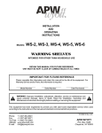
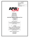
APW/WYOTT EQUIPMENT LIMITED WARRANTY
IMPORTANT
APW/WYOTT Foodservice Equipment Company warrants its equipment against defects in materials and workmanship,
subject to the following conditions:
FOR FUTURE REFERENCE
Please complete this information
and retain this manual for the life
of the equipment.
MODEL #———————————————————
SERIAL #———————————————————
DATE PURCHASED——————————————
For Warranty Service and/or Parts this
information is required.
This warranty applies to the original owner only and is not assignable.
Should any product fail to function in its intended manner under normal use within the limits defined in this warranty, at the
option of APW/WYOTT such product will be repaired or replaced by APW/WYOTT or its Authorized Service Agency. APW/
WYOTT will only be responsible for charges incurred or service performed by its Authorized Agencies. The use of other
than APW/WYOTT Authorized Service Agencies will void this warranty and APW/WYOTT will not be responsible for such
work or any charges associated with same. The closest APW/WYOTT Authorized Service Agency must be used.
This warranty covers products shipped into the 48 contiguous United States, Hawaii, metropolitan areas of Alaska and
Canada. There will be no labor coverage for equipment located on any island not connected by roadway to the mainland.
TIME PERIOD:
One-year parts, one-year labor, effective from the date of purchase by the original owner. The Authorized Service Agency
may, at their option, require proof of purchase. Parts replaced under this warranty are warranted for the unexpired portion of
the original product warranty only.
EXCEPTIONS:
*Gas/Electric Cookline - Models GCB, GCRB, GF, GGM, GGT, GHP-H, GWW, EBC, EF, EG, EHP, EWW
Three (3) Year Warranty on all component part, except switches and thermostats. (2 additional years on parts only - No
labor on second or third year.)
*Heat Strips - Models FD - Two (2) Year Warranty on element only - No labor second year.
*Glass Windows, Door Seals, Rubber Seals, Light Bulbs, Broiler Briquettes 90 Day Material Only - No labor.
PRODUCT MANUAL
In all cases parts covered by extended warranty will be shipped FOB the factory after the first year.
PORTABLE CARRY-IN PRODUCTS
Equipment weighing over 70 pounds or permanently installed will be serviced on-site as per the terms of this warranty.
Equipment weighing 70 pounds or under, and which is not permanently installed (i.e.; with cord and plug) is considered
portable and is subject to the following warranty handling limitations.
If portable equipment fails to operate in its intended manner on the first day of connection, or use, at APW/WYOTT's option
or its Authorized Service Agency, it will be serviced on-site or replaced.
From day two through the conclusion of this warranty, portable units must be taken or sent prepaid to the APW/WYOTT
Authorized Service Agency for in-warranty repairs. No mileage or travel charges are allowed on portable units after the first
day of use. If the customer wants on-site service they may receive same by paying the travel and mileage charges.
EXCLUSIONS:
The following conditions are not covered by warranty.
*Equipment failure relating to improper installation, improper utility connection or supply and problems due to
ventilation.
*Equipment that has not been properly maintained, calibration of controls, adjustments, damage from improper cleaning and water damaged controls.
*Equipment that has not been used in an appropriate manner, or has been subject to misuse or misapplication, neglect, abuse, accident, alteration, negligence, damage during transit, delivery or installation, fire, flood, not or act of
God.
*Equipment that has had the model number or serial number removed or altered.
If the equipment has been changed, altered, modified or repaired by other than a qualified service technician during or after
the warranty period then the manufacturer shall not be liable for any damages to any person or property which may result
from the use of the equipment thereafter.
This warranty does not cover services performed at overtime or premium labor rates. Should service be required at times
which normally involve overtime or premium labor rates, the owner shall be charged for the difference between normal
service rates and such premium rates APW/WYOTT does not assume any liability for extended delays in replacing or repairing any items beyond its control.
In all cases the use of other than APW/WYOTT authorized OEM replacement parts will void this warranty.
This equipment is intended for commercial use only. Warranty is void if equipment is installed in other than commercial
application.
THE FOREGOING WARRANTY IS IN LIEU OF ANY AND ALL OTHER WARRANTIES EXPRESSED OR IMPLIED INCLUDING ANY IMPLIED WARRANTY OF MERCHANTABILITY OR FITNESS AND CONSTITUTES THE ENTIRE LIABILITY OF APW/WYOTT IN NO EVENT DOES THE LIMITED WARRANTY EXTEND BEYOND THE TERMS STATED
HEREIN.
P/n 88939-20, 01/01
12
Safety Instructions
Installation Instructions
Operation Instructions
Maintenance Instructions
Replacement Parts List
HOTROD® Roller Grills
Slanted HOTROD® Roller Grills
Full Menu HOTROD® Roller Grills
FOR YOUR SAFETY
Do not store or use gasoline or other flammable vapors or
liquids in the vicinity of this or any other appliance.
!
WARNING
Improper installation, adjustment, alteration, service or maintenance can
cause property damage, injury or death. Read the installation, operating
and maintenance instructions thoroughly before installing or servicing this
equipment.
APW/WYOTT Foodservice Equipment Co.
P.O. Box 1829
Cheyenne, WY 82003
(307) 634-5801
FAX(307) 637-8071
THIS MANUAL SHOULD BE RETAINED FOR FUTURE REFERENCE
! CAUTION
These models are designed, built and sold for commercial use. If these models are positioned
so the general public can use the equipment, make sure that all cautions, warnings and operating instructions are clearly posted near each unit so that anyone using the equipment will
use it correctly and not injure themselves or harm the equipment.
! WARNING
CHECK THE DATA PLATE ON THIS UNIT BEFORE INSTALLATION. CONNECT THE UNIT
ONLY TO THE VOLTAGE AND FREQUENCY LISTED ON THE DATA PLATE. CONNECT
ONLY TO 1 OR 3 PHASE AS LISTED ON THE DATA PLATE.
!
WARNING
Improper installation, operation, service or maintenance can cause property damage, injury or
death. Read these instructions thoroughly before installing, operating, maintaining or servicing
this equipment.
!
WARNING
ELECTRICAL AND GROUNDING CONNECTIONS MUST COMPLY WITH THE APPLICABLE
PORTIONS OF THE NATIONAL ELECTRICAL CODE AND/OR OTHER LOCAL CODES.
!
WARNING
DISCONNECT ELECTRICAL POWER SUPPLY AND PLACE A TAG AT THE DISCONNECT
SWITCH INDICATING THAT YOU ARE WORKING ON THE CIRCUIT.
Install according to the spacing requirements listed in the installation section of this manual.
We strongly recommend having a competent professional install this equipment. A licensed
electrician should make the electrical connections and connect power to the unit. Local codes
should always be used when connecting these units to electrical power. In the absence of
local codes, use the latest version of the National Electrical Code.
Maintenance and repair should be handled by a factory authorized agent. Before doing any
maintenance or repair, contact APW/Wyott.
ITEM
15
16
18
19
20
21
22
23
24
25
26
27
28
29
DESCRIPTION
MOTOR GEAR
DRIVE MOTOR FAN
TIE ROD, SLANT UNITS
PART NO.
217485-10
12065-10
217488-20
217488-30
217488-31
217488-50
FOOT, RUBBER
217014-61
FOOT, 1" ADJUSTABLE
86621-00
INSERT FOR ADJ. FOOT
84840-00
DRIP PAN
217484-20
217484-30
217714-12
217484-50
217714-20
217524-88
ELEMENT RETAINER
217481-00
217490-00
217714-22
217524-91
ELEMENT SUPPORT
217480-00
217491-00
217714-24
217524-90
SCREW, #6-32 X 1-3/4
81139-00
#6 LOCK WASHER
85015-00
FLAT WASHER
85072-00
#6-32 KEPS NUT
84001-00
#8-32 X 3/8 HEX HD SCREW 81531-00
#8-32 X 3/8 PAN HD SCREW 81300-00
#10-32 KEPS NUT
84171-00
IMMEDIATELY INSPECT FOR SHIPPING DAMAGE
All containers should be examined for damage before and during unloading. The freight carrier has assumed responsibility for its safe transit and delivery. If equipment is received damaged, either apparent or concealed, a claim must be made with the delivering carrier.
A) Apparent damage or loss must be noted on the freight bill at the time of delivery. It must
then be signed by the carrier representative (Driver). If this is not done, the carrier may refuse
the claim. The carrier can supply the necessary forms.
B) If there is concealed damage or loss, if not apparent until after equipment is uncrated, a
request for inspection must be made to the carrier within 15 days. The carrier should arrange
an inspection. Be certain to hold all contents and packaging material.
Installation and start-up should be performed by a qualified installer who thoroughly read,
understands and follows these instructions.
If you have questions concerning the installation, operation, maintenance or service of this
product, write Technical Service Department APW/Wyott Foodservice Equipment Company,
P.O. Box 1829, Cheyenne, WY 82003.
2
11
UNIT
ALL UNITS
ALL UNITS
FOR "-20" UNITS
FOR "-30" UNITS
FOR "-31" UNITS
FOR "-50" UNITS
FOR "-20" UNITS
FOR "-30" UNITS
FOR "-31" UNITS
FOR "-50" UNITS
FOR "-45" UNITS
FOR "-75 & -85" UNITS
ALL FLAT "-20, -30, -31, -50"
ALL SLANT "-20, -30, -31, -50"
FOR "-45 & -75" UNITS
FOR "-85" UNITS
ALL FLAT "-20, -30, -31, -50"
ALL SLANT "-20, -30, -31, -50"
FOR "-45 & -75" UNITS
FOR "-85" UNITS
MOTOR HARDWARE
MOTOR HARDWARE
MOTOR HARDWARE
MOTOR HARDWARE
FOR ELEMENTS
FOR BOTTOM PANEL
FOR ELEMENT SUPPORTS
ITEM
1
2
3
DESCRIPTION
POWER SWITCH
KNOB, CONTROL
INFINITE SWITCH
4
5
INDICATOR LIGHT
CONTROL PANEL DECAL
6
7
8
9
10
11
12
13
14
PART NO.
13318-00
87056-00
13279-00
13282-00
15139-03
88065-23
88065-20
88065-31
88065-21
15325-01
UNIT
ALL UNITS
ALL UNITS
ALL 120 VOLT UNITS
ALL 208/240 VOLT UNITS
ALL UNITS
FOR "-20" UNITS
FOR "-30" UNITS
FOR "-31& -45" UNITS
FOR "-50, -75 & -85" UNITS
FOR 120 VOLT "-20 & -30" UNITS
POWER CORD, AWG 18/3,
5-15P
AWG 14/3, 5-15P 15420-02 FOR 120 VOLT "-20, -30, -31, -45 & -50" UNITS
AWG 14/3, 6-15P 15420-05 FOR 208/240 VOLT "-30, -31, -45, -50 &-75"
UNITS
AWG 14/3, 6-15P 15319-00
FOR 208/240 VOLT "-85" UNITS
STRAIN RELIEF
89674-00
FOR POWER CORD 15325-01
89689-00 FOR POWER CORDS 15420-02 & 15420-05
89675-00
FOR POWER CORD 15319-00
HEATING ELEMENT
14315-20
FOR "-20" UNITS, 120 VOLT
14315-30
FOR "-30" UNITS, 120 VOLT
14314-30
FOR "-30" UNITS, 208/240 VOLT
14315-32
FOR "-31, -45" UNITS, 120 VOLT
14315-33
FOR "-31, -45" UNITS, 208/240 VOLT
14315-50
FOR "-50" UNITS, 120 VOLT
14314-50
FOR "-50, -75, -85" UNITS, 208/240 VOLT
CHAIN GUIDE
217483-00
FOR FLAT UNITS, "-20, -30, -31, -50"
217714-00
FOR "-45, -75, -85"
217494-00
FOR SLANT UNITS, "-20, -30, -31, -50"
217714-28
FOR "-45 & -75" UNITS
217524-96
FOR "-85" UNITS
CHAIN, DRIVE
217485-05
FLAT UNITS, "-20, -30, -31, -50"
217485-06
SLANT UNITS , "-20, -30, -31, -50"
217485-09
FOR "-45 & -75" UNITS
217485-07
FOR "-85" UNITS
BEARING, ROLLER TUBE 217489-00
ALL UNITS
GREASE SEAL, TUBE
4223-00
ALL UNITS
ROLLER, CHROME PLATED 217475-20
FOR "-20" UNITS
217475-30
FOR "-30" UNITS
217714-31
FOR "-31, -45" UNITS
217476-50
FOR "-50, -75, -85" UNITS
ROLLER, XYLAN COATED 217523-20
FOR "-20" UNITS
217523-30
FOR "-30" UNITS
217714-17
FOR "-31, -45" UNITS
217523-50
FOR "-50, -75, -85" UNITS
MOTOR, ROLLER DRIVE
12120-00
ALL UNITS AT 120 VOLT
12118-00
ALL UNITS AT 208/240 VOLT
12123-00
FOR "-45, -75, -85" REVERSED 120 VOLT
12117-00
FOR "-45, -75, -85" REVERSED 240 VOLT
10
Congratulations on your purchase of APW/Wyott commercial cooking or refrigeration
equipment. APW/Wyott takes pride in the design and quality of our products. When used
as intended and with proper care and maintenance, you will experience years of reliable
operation from this equipment. To ensure best results, it is important that you read and
follow the instructions in this manual carefully.
TABLE OF CONTENTS:
Safety Precautions .......................................................... 2, 3
Specifications ...................................................................... 4
Installation ....................................................................... 5, 6
Operating Instructions ..................................................... 5, 6
Cleaning / Maintenance................................................5, 6, 7
Service ............................................................................ 5, 7
Wiring Diagrams ............................................................. 7, 8
Parts Diagram ..................................................................... 9
Parts List ......................................................................10, 11
Warranty ........................................................................... 12
LOCATION OF DATA PLATE
The data plate is located on the back of the unit.
SAFETY PRECAUTIONS
Before installing and operating this equipment be, sure everyone involved in its operation is fully trained and is aware of all
precautions. Accidents and problems can result by a failure to follow fundamental rules and precautions.
The following words and symbols, found in this manual, alert you to hazards to the operator, service personnel or the equipment. The words are defined as follows:
! DANGER
This symbol warns of imminent hazard which will result in serious injury or death.
! WARNING
This symbol refers to a potential hazard or unsafe practice which could result in serious injury or death.
! CAUTION
This symbol refers to a potential hazard or unsafe practice which may result in minor or moderate injury or product or
property damage.
NOTICE
This symbol refers to information that needs special attention or must be fully understood even though not dangerous.
NOTICE
This product is intended for commercial use only. Not for household use.
! CAUTION
The models are designed, built and sold for commercial use. If these models are positioned so the general public can use the
equipment, make sure that all cautions, warnings and operating instructions are clearly posted near each unit so that anyone
using the equipment will use it correctly and not injure themselves or harm the equipment.
! WARNING
SHOCK HAZARD
Do not open any panels that require the use of tools.
! WARNING
Improper installation, service, or maintenance can cause property damage, injury or death.
NOTICE: THE UNIT, WHEN INSTALLED, MUST BE ELECTRICALLY GROUNDED AND COMPLY WITH LOCAL CODES,
OR IN THE ABSENCE OF LOCAL CODES, WITH THE NATIONAL ELECTRICAL CODE ANSI/NFPA 70-LATEST EDITION.
CANADIAN INSTALLATION MUST COMPLY WITH CSA-STANDARD C.22.2 No. 0 M1982 General Requirements - Canadian Electrical Code, Part II, 109-M1981 - Commercial Cooking Appliances.
NOTICE: Local codes regarding installation vary greatly from one area to another. The National Fire Protection Association,
Inc., states in its NFPA 96 latest edition that local codes are "authority having jurisdiction" when it comes to requirements for
installation of equipment. Therefore, installations should comply with all Local codes.
3
Specifications:
HR-20, HRS-20
120 Volt, 60 Hz, 6.4 AMP
8-1/2” H x 17-1/4” W x 18-5/8” D
HR-20SW, HRS-20SW, HRS-20W
120 Volt, 60 Hz, 5.9 AMP
11-1/2” H x 17-1/4” W x 18-5/8” D
HR-30, HRS-30
120 Volts, 60 Hz, 7.8 AMP or
220 Volts, 60 Hz, 4.2 AMP
8-1/2” H x 22-3/4” W x 18-3/8” D
HR-30S, HRS-30S
120 Volts, 60 Hz, 7.8 AMP or
220 Volts, 60 Hz, 4.2 AMP
11-1/2” H x 22-3/4” W x 18-3/8” D
HR-31, HRS-31
120 Volts, 60 Hz, 8.3 AMP or
208/240 Volts, 60 Hz, 4.8/4.2 AMP
8-1/2” H x 23-3/4” W x 18-5/8” D
HR-31SW, HRS-31SW, HR-31SRW,
HRS-31SRW, HRS-31W
120 Volts, 60 Hz, 7.5 AMP or
208/240 Volts, 60 Hz, 4.4/3.8 AMP
11-1/2” H x 23-3/4” W x 18-5/8” D
HR-45W, HRS-45W
120 Volts, 60 HZ, 12.2 AMP or
208/240 Volts, 60 Hz, 7.1/6.2 AMP
10-1/4” H x 23-3/4” W x 29-9/16” D
HR-50, HRS-50
120 Volts, 60 Hz, 12.0 AMP or
208/240 Volts, 60 Hz, 7.0/6.1 AMP
8-1/2” H x 34-3/4” W x 18-5/8” D
HR-50S, HRS-50S, HR-50SRW,
HRS-50SRW, HRS-50W
120 Volts, 60 HZ, 11.0 AMP or
208/240 Volts, 60 Hz, 6.4/5.5 AMP
11-1/2” H x 34-3/4” W x 18-5/8” D
BACK
FRONT
LO
HI
LO
2
8
2
3
HRS-75W
208/240 Volts, 60 Hz, 10.2/8.8 AMP
10-1/4” H x 34-3/4” W x 29-9/16” D
HR-85, HRS-85
208/240 Volts, 60 Hz, 9.5/11.0 AMP
10-1/4” H x 34-3/4” W x 29-9/16” D
4
7
4
9
6
HI
8
3
7
4
6
General Installation Instructions:
The unit has been inspected and tested at the factory prior to shipment.
Unpack the unit and remove all packing materials. Place on a flat horizontal surface at the
desired location.
! WARNING
CHECK THE DATA PLATE ON THIS UNIT BEFORE INSTALLATION. CONNECT ONLY TO
THE VOLTAGE AND FREQUENCY LISTED ON THE DATA PLATE. CONNECT ONLY TO 1
OR 3 PHASE AS LISTED ON THE DATA PLATE.
! WARNING: IMPROPER GROUNDING COULD RESULT IN ELECTRICAL SHOCK
This appliance is equipped with a three-prong (grounded) plug for your protection against
electrical shock hazard and should be plugged directly into a properly grounded three-prong
receptacle. Do not cut or remove the grounding prong from this plug.
! CAUTION
DO NOT USE ordinary steel wool as any particles left on the surface will rust.
NEVER USE a wire brush, steel or abrasive scouring pads (except stainless), scraper, file or
other steel tools. Surfaces which are marred collect dirt more rapidly and become more difficult to clean. Marring also increases the possibility of corrosive attack.
NEVER use any corrosive cleaner. Use only cleaners approved for stainless steel.
NEVER use cleaning solvents with hydrocarbon base.
General Installation
1. Always clean equipment thoroughly before first use. (See general cleaning instructions.)
2. Check ratings label for your model designation and electrical ratings.
3. For best results, use stainless steel countertops.
4. Attach legs to unit.
General Operation Instructions
1. Trained personnel should operate all food service equipment.
2. Do not allow your customers to come into contact with any surface labeled “CAUTION
HOT”.
3. Where applicable, never pour cold water into dry heated units.
4. Where applicable, do not cook, warm or hold food directly in liner/well pans. Always
use steam table pans/inserts, etc.
5. NEVER hold food below 40 degrees F.
Wiring Diagram for 10 tube units
General Cleaning Instructions
1. Never clean any electrical unit by immersing it in water. Turn the unit off and allow it to
cool before surface cleaning.
2. Always clean equipment thoroughly before first use. Clean unit daily. Except where
noted on charts: use warm, soapy water. Mild cleansers and plastic scouring pads may
be used to remove baked-on food and water scale on metal unit. NOTE: do not clean
roller tubes with abrasive cleaners or scouring pads. Follow instructions on page 4.
3. Unplug electrical unit before cleaning or servicing. All service should be performed by
an APW/Wyott authorized service agency.
General Troubleshooting
Always ask and check:
1. Is the unit connected to a live power source?
2. Check the circuit breaker.
3. Is power switch on and pilot light glowing?
4. Check the rating label. Are you operating unit on the proper voltage?
If the above checks out and you still have problems, call an APW/Wyott authorized service
agency.
8
5
INSTALLATION
PERIODIC CLEANING THROUGHOUT THE DAY
Place the HOTROD® directly on a countertop or on a matching APW/Wyott Bun Warmer or Bun
Cabinet (available separately). Place the unit close to an AC outlet, of the correct voltage, to avoid
undue strain on the power cord.
1.
2.
CAUTION: To avoid equipment damage, make certain that the nameplate voltage is the same as
the outlet voltage.
If the plug is to be removed and replaced with a plug more suitable for your area, the color code
for the power cable is:
Neutral (N)
=
White or Blue
Live (L)
=
Black or Brown
Safety Earth (E)
=
Green or Yellow/Green
After a suitable location has been chosen, wipe the rollers and the drip pan with a damp cloth. The
unit is ready for use.
For high-volume applications or for product that has a high fat content, clean the rollers
every 3-4 hours.
Clean by removing the product from the rollers and wiping with a damp cloth from outside end of the rollers to the center. Replace the product and continue cooking. There
should be no need to turn off the heat when wiping down the rollers. But care should be
taken not to bring hands into direct contact with the rollers as a burn could result.
NOTE: THIS APPLIANCE SHALL NOT EB CLEANED WITH A WATER JET.
SERVICE
Service work should be performed only by a qualified technician who is experienced in and knowledgeable with
the operation of commercial gas, electric, steam cooking equipment. Contact the Authorized Service Agency for
reliable service, dependable advice or other assistance and for genuine factory parts.
IF THE SUPPLY CORD IS DAMAGED, IT MUST BE REPLACED BY THE MANUFACTURER
OR ITS SERVICE AGENT OR A SIMILARLY QUALIFIED PERSON IN ORDER TO AVOID A
HAZARD.
OPERATION
WARNING: This unit is not intended to hold potentially hazardous foods such as uncooked or unpreserved meats and sausages.
There are three simple controls on the front of this unit: a switch, which controls the tube rotation,
and two adjustable heat controls, which activates the two banks of heating elements in the roller
tubes. Both heat controls have a light above them indicating either “Front” or “Back”. The front
heat control activates the first 5 or 6 (depending on if your unit has 10 or 11 tubes). The back control activates the remaining 5 tubes. Each bank of tubes can be heated independently of the others
and at separate temperature settings. Variations in voltage and ventilation make experimenting the
best guide to power level adjustment.
When a preferred adjustment is found, and it is desired to return consistently to the same spot on
the controls, the controls can be fine-tuned by aligning with a mark on the knob. This adjustment
does not require a service visit.
Daily Cleaning Instructions
1.
2.
3.
Heat the unit.
Using a moist cloth filled with crushed or flaked ice, wipe each tube. Wipe the tubes
from each end to the center. This will keep as much of the loosened particles out of the
bearings as possible. Extend the cloth as far as possible between the rollers.
With the heated rollers wiped with an ice filled cloth to loosen the particles, now, wipe
clean with another cloth. Continue to wipe from the end of the rollers to the center. This
will reduce the grease and partials getting into the bearings and drive mechanism. This
will extend the life of the unit and extend the period between routine maintenance of the
drive mechanism.
CAUTION: NEVER use abrasive powders or pads; these cleaners may damage the roller finish.
Also, the particles may get into the drive mechanism shortening the unit life.
4. Remove the drip pan and wash it in hot, soapy water, then rinse.
5. If stains are still present, add a light detergent to the cloth and repeat.
6. Replace the pan and turn the unit off if the grill will not be immediately used.
NOTE: Cleanup will be faster if the product is specifically made for cooking on roller grills. Several
meat packers now offer this product.
For high-volume applications or for products that have a high sugar or fat content, the HOTROD®
may require more frequent cleaning. For longer life of your HOTROD®, follow instructions for periodic cleaning throughout the day.
6
Wiring Diagram for
11 tube units
7