1
PROJECT: TO: ATTN: Ph/Fax: o 5995 Greenwood Plaza Blvd, Suite 100 Greenwood Village, CO 80111 303-571-5377 Fax 303-629-7467 o 496 Nevada Mesa View Colorado Springs, CO 80907 719-633-4673 Fax 719-471-3169 TRANSMITTAL No. 11J19830037 DATE: 02/03/2012 PCC Center Expansion T&T Electric Co Inc 1824 Aspen Cr Pueblo CO 81006 RE: 16000-Electrical - T&T Scott Smith JOB: 719)240-0394 WE ARE SENDING: SUBMITTED FOR: 11J1983 ACTION TAKEN: Approved as Submitted Shop Drawings Approval Letter Your Use Prints As Requested Returned After Loan Change Order Review and Comment Resubmit x Approved as Noted Submit Plans SENT VIA: Samples Returned Specifications / Product Data Attached Returned for Corrections Other: Separate Cover Via: Due Date: 04/03/2012 NOTES: Item Package Code Submittal 16000 16231-01 1 02/03/2012 Submittal 16000 16231-02 1 02/03/2012 Submittal 16000 16231-03 1 02/03/2012 Rev. Copies Date Description Status Packaged Engine Generators - product data Packaged Engine Generators - shop drawings Packaged Engine Generators qualification data of Manufacturer Approved As Noted Approved As Noted Approved As Noted CC: Signed: Tyler Read 7333 W. Jefferson Ave. Suite 230 Lakewood, Colorado 80235 303y986y8200 Voice 303y986y8222 Facsimile www.sbengr.com Letter of Transmittal To: Nathan Miesen, AIA Date: February 2, 2012 Company: Oz Architecture From: 1805 29th St. Suite 2054 Project Name: Nancy White Pueblo Community College – Student Center Boulder, CO 80301 SBEC #: 110005 This Information is Being Sent Via: Regular Mail Express Mail Messenger E-Mail Enclosed Are the Following Drawings Disk(s) Originals Change Order Product Literature Attachments Copies: 1 Date: 01-19-12 These Are Transmitted: For Your Use For Approval Letter Specifications Description: 16231-01 – Packaged Engine Generators After Loan To Us Reviewed As Requested For Your Record For Review/Comment ____________________ Remarks: From: Copy To: SBEC File If enclosures are not as listed, please notify our office P:\2011\110005 -- PCC - College Center Expansion\Submittals\Electrical\16231 - Packaged Engine Generator\16231-01, 2012.01.19\LOT Miesen, 2012.02.02.doc 7333 W. Jefferson Ave. Suite 230 Lakewood, Colorado 80235 303y986y8200 Voice 303y986y8222 Facsimile www.sbengr.com Construction Submittal Review Sheet Project Name: PCC – Student Center Architect Log #: SBEC#: 110005 Contractor Log #: SBEC Log # and/or submittal title: 16231-01 Packaged Engine Generators Owner Project #: Page: 1 OF Item: Manufacturer: Engine Generator Generator control system Output circuit breaker Battery Battery charger Remote annunciator Drawings, wiring diagrams Generator warranty Cummins Cummins Square D Deka SENS Cummins Cummins Cummins Date Received: 1 Reviewed As Noted Make Corrections Noted Rejected Revise and Resubmit 16231-01, 02, 03 01-19-12 Submit Specified Item Remarks X 1,2 X 3 X 4 X X X X X Remarks: 1. Full rating of engine generator shall be available at an altitude of 6000 feet. Refer to specification section 16231, paragraph 1.6 A. 2. Remote emergency-stop switch shall be mounted outside or on the exterior of the generator housing. 3. Provide selective coordination per the NEC. 4. Warranty period shall be 5 years from the date of Substantial Completion. Refer to specification section 16231, paragraph 1.8 A. 5. 6. 7. 8. 9. Note: This review is only for general conformance with the design concept of the project and general compliance with the information given in the Contract Documents. Corrections or comments made concerning the shop drawing during this review do not relieve contractor from compliance with the requirements of the plans and specifications. Review of a specific item shall not include approval of an assembly of which the item is a component. Contractor is responsible for: dimensions to be confirmed and correlated at fabrication processes or to the means, methods, techniques, sequences and procedures of construction; coordination of their work with that of all other trades; and for performing all work in a safe and satisfactory manner. Signed (Mechanical): Date: Signed (Electrical): Nancy White, P.E. Date: 02-02-12 P:\2011\110005 -- PCC - College Center Expansion\Submittals\Electrical\16231 - Packaged Engine Generator\16231-01, 2012.01.19\16231-01 CSRS.doc PROJECT: TO: ATTN: o 5995 Greenwood Plaza Blvd, Suite 100 Greenwood Village, CO 80111 303-571-5377 Fax 303-629-7467 o 496 Nevada Mesa View Colorado Springs, CO 80907 719-633-4673 Fax 719-471-3169 No. 11J19830001 DATE: 01/19/2012 PCC Center Expansion OZ Architecture of Boulder Inc 1805 29th St Ste 2054 Boulder CO 80301 RE: 16000-Electrical - T&T Nathan Miesen JOB: Ph/Fax: WE ARE SENDING: x TRANSMITTAL SUBMITTED FOR: 11J1983 ACTION TAKEN: Approval Approved as Submitted Letter Your Use Approved as Noted Prints As Requested Returned After Loan Change Order Review and Comment Resubmit Shop Drawings x Submit Plans SENT VIA: Samples x Returned Specifications / Product Data Attached Returned for Corrections Other: Separate Cover Via: Due Date: 02/02/2012 NOTES: Item Package Code Submittal 16000 16231-01 1 01/19/2012 Submittal 16000 16231-02 1 01/19/2012 Submittal 16000 16231-03 1 01/19/2012 2/2/12 N. White Rev. Copies Date Description Status Packaged Engine Generators - product Architect Review data Packaged Engine Generators - shop Architect Review drawings Packaged Engine Generators Architect Review qualification data CC: Refer to the attached Construction Submittal Review Sheet for comments Signed: Tyler Read Submittal Stamp Sheet GH Phipps Construction Companies 496 Nevada Mesa View Colorado Springs, CO 80907 OZ Architecture of Boulder Inc 1805 29th St Ste 2054 Boulder CO 80301 Pueblo Community College College Center Expansion 11J1983 1/19/2012 Subcontractor: T&T Electric Spec Section: 16231 Submitted For: For Approval Resubmittal For Record Only y Spec Heading: Packaged Engine Generators Paragraph/ Drawing #: 1.4 Included: Samples Shop Drawings Product Data Comments: SUBMITTED GH Phipps 1/19/2012 GH Phipps has reviewed, approved, and herby submits the attached in accordance with the contract documents. Note to Subcontractor/ Material Supplier: Subcontractor/ Material Supplier remains responsible for the confirmation and correlation of dimensions at the jobsite; fabrication processes and construction techniques; coordination of the work with the work of other trades; and satisfactory performance of the work. By: Tyler Read - Project Engineer Power Generation Division 8211 East 96th Avenue Henderson, CO 80640 Project: Pueblo Community College Student Center Contractor: T&T Electric Submittal: #1 Date: 01/17/12 20 kW Diesel Generator Set Sales Representative: Brian Taylor Phone: 303-927-2248 Email: [email protected] This Page Left Intentionally Blank Generator Package Weight 220.00 424.00 Weight in Kilograms 588.76 0.00 99.79 192.32 268.40 121.74 Weight in Pounds Weight in Kilograms Total Ship Weight without Fuel 2,210.40 1,002.62 Total Pad Weight with Fuel Weight in Pounds 3,010.40 Weight in Kilograms 1,365.49 Generator Wet Weight (oil & coolant) Exhaust Silencer Enclosure Fuel Tank Accessories Weight in Pounds 1,298.00 This Page Left Intentionally Blank Bill of Materials Pueblo Community College Student Center 20 kW Generator Set T&T Electric CRM Project #63495, Revision # 0, Date 01/16/12 Line Qty. 1 2 3 4 5 6 7 8 9 10 11 12 13 14 15 16 17 18 19 20 21 22 23 24 25 26 27 28 29 30 31 32 33 34 35 36 01/18/12 CC Description Part Number U.S. EPA, Stationary Emergency Application Install-US-Stat Genset-Diesel,60Hz,20kW-Standby Rating 20DSKBA Duty Rating-Standby Power A331-2 Listing-UL 2200 L090-2 EmissionsCertification,EPA,Nonroad,Tier4,CFR1039 L149-2 Enclosure-Steel,Weather Protective,with ExhSys F182-2 Voltage-277/480,3 Phase,Wye,4 Wire R002-2 Alternator-60Hz,12 Lead,Broad Range,105C B256-2 GENSET CONTROL-POWERCOMMAND 1.1 H700-2 Exciter/Regulator-Torque Match B240-2 Engine Governor-Electronic, Isochronous Only A366-2 Display Language-English H536-2 Meters-AC Output,Analog H606-2 Stop Switch-Emergency K796-2 Control Mounting-Front Facing H679-2 Circuit Ci it Breaker B k Or O Entrance E t Box-Right B Ri ht Side Sid Only O l KP80 KP80-2 2 CircuitBreaker-40A,Right,3P,600VAC,80%,UL KS94-2 Listing, ULC-S601-07 L163-2 Wind Rating-150 MPH,Steel Housing F206-2 Fuel Tank-Dual Wall Sub-Base, 24 Hour Min Capacity C266-2 Switch-Low Fuel Level, Subbase C157-2 Switch-Rupture Basin C158-2 Skidbase-Housing Ready F179-2 Engine Starter - 12 VDC Motor A422-2 Battery Charging Alternator-Normal Output A333-2 Engine Cooling-High Ambient Air Temperature E125-2 Shutdown-Low Coolant Level H389-2 Extension-Engine Coolant Drain E089-2 Coolant Heater-120 Volt Ac, Single Phase H036-2 Engine Air Cleaner-Heavy Duty D036-2 Genset warranty- Base, Standby 2 years / 400 hours, Prime Power L028-2 Packing-Skid, Poly Bag A322-2 Rack-Battery F065-2 Extension-Oil Drain H268-2 Common Parts Listing CP01-2 Product Revision - B SPEC-B Project #63495 Bill of Materials Pueblo Community College Student Center 20 kW Generator Set T&T Electric CRM Project #63495, Revision # 0, Date 01/16/12 Line Qty. 37 38 39 40 41 42 43 44 45 46 47 48 49 50 51 52 53 54 55 56 57 58 59 60 61 62 63 64 65 66 67 68 69 70 01/18/12 CC Description Water Jacket Heaters, Single Phase 120 VAC = 1,000 Watts / 8.33 Amps 1 1 1 Part Number H036 Configurable Inputs - PCC1.1 Control Configurable Inputs: Warning, Shutdown, or Status Indication with Message Displayed on LCD Display Customer Input #1 - Charger AC Fail Customer Input #2 - Rupture Basin Alarm Standard Configurable Relay Outputs - PCC1.1 Control Configurable Relay Outputs: 2 Amp @ 30 VDC / 3 Amp @ 120 VAC Relay Output #1 - Common Alarm, Warning Faults Relay Output #2 - Common Alarm, Shutdown Faults Remote Annunciator-PCCnet Network RS485 Cummins Remote PCCnet Network Annunciator Panel20 Light, RS485, Flush/Surface NEMA Type 1 Enclosure Cust. Fault #1 - Spare Cust. Fault #2 - Spare Cust. Fault #3 - Rupture Basin Alarm Contractor Note: PCCnet RS485 Cabling Requirements. Requires Twin Power Conductors, Stranded Twisted Pair, Shielded Network Data Cable. (Belden 9729) Installation By Electrical Contractor NFPA110 0300-5929-02 Project #63495 Bill of Materials Pueblo Community College Student Center 20 kW Generator Set T&T Electric CRM Project #63495, Revision # 0, Date 01/16/12 Line Qty. 71 72 73 74 75 76 77 78 79 80 81 82 83 84 85 86 87 88 89 90 91 92 93 94 95 96 97 98 99 100 101 102 103 104 1 Description KS94/150 Amp H-Frame/40 Amp Trip (Main Line Circuit Breaker) Cummins/Square D Local Main Line Circuit Breaker Ref. Square D Catalog #0611CT0401R7/05 Square D/PowerPact 150 Amp HG-Frame/40 Amp Trip UL Listed, 3-Pole, 80% Rated Interrupting Rating 65 kA @ 240 VAC Interrupting Rating 35 kA @ 480 VAC Molded Case, Thermo-Magnetic Trip Unit NEMA Type 1 Enclosure Full Neutral Bus & Ground Bond Mechanical Lugs: (1) #14 AWG-3/0 AWG AL or CU Per Phase (Mounted Right Side Of The Control Panel) Cummins Engine Coolant & Lube Oil 1-Lot Initial Fill of Engine Coolant, Ethylene Glycol 1-Lot Initial Fill of Lube Oil, Cummins Blue 01/18/12 CC 1 Cummins Factory Testing Cummins Typical Generator Set Production Test 1 Cummins Generator Set Warranty Warranty: 2-Year Base Warranty - Emergency Standby Power From Initial Date Of Start-Up 1 Engine Starting Batteries Engine Starting Battery, Group 31 Lead/Acid Type 12 VDC, Maintenance Free 1 1 Part Number Engine Starting Batteries Warming Pads Battery Warming Pad, 120 VAC, 60 Watt Thermostat, On at 40oF, Off at 60oF KS94 50/50 15W/40 CPG TGSPT L028 1131XPMF BH4 DIT46 Project #63495 Bill of Materials Pueblo Community College Student Center 20 kW Generator Set T&T Electric CRM Project #63495, Revision # 0, Date 01/16/12 Line Qty. 105 106 107 108 109 110 111 112 113 114 115 116 117 118 119 120 121 122 123 124 125 126 127 128 129 130 131 132 133 134 135 136 137 138 01/18/12 CC 1 1 1 1 Description SENS 10 Amp Battery Charging System SENS EnerGenius Battery Charger, NFPA-110 Alarms 10 Amp @ 12/24 VDC Output, 60HZ-120/208-240 VAC Input F182 - Steel UL2200 Listed Weather Protective Enclosure Steel Weather Protective Enclosure Package Compliant with UL2200 Listed Gensets NEC Compliant Sound Levels @ 7 Meters = 82.4 dB(A) (When Tested In A Free Field Environment) Drop-Over Style - With Or Without Fuel Tank Internally Mounted Exhaust Silencer W/ Rain Cap 14 Gauge (Panels) 12 Gauge (Posts) Steel Construction Three Hinged, Recessed, Key Lockable Doors Fixed Louvers Air-Inlet Radiator Air-Discharge-With Screened Outlet Corrosion Resistant Hardware Cambered Roof Easy Access Lifting Points Optional-Wind Rated To 150mph - Steel Enclosure All Electrical Wired To Terminal Strip Located InsideThe Circuit Breaker Can Double E-Coat Paint - Onan Green Part Number NRG22-10-RC F182 F206 Project #63495 Bill of Materials Pueblo Community College Student Center 20 kW Generator Set T&T Electric CRM Project #63495, Revision # 0, Date 01/16/12 Line Qty. 139 140 141 142 143 144 145 146 147 148 149 150 151 152 153 154 155 156 157 158 159 160 161 162 163 164 165 166 167 168 169 170 171 172 01/18/12 CC Description 1 1 1 1 100 Gallon Fuel Tank-C266 Cummins Double Wall Base Fuel Tank Fuel Tank Capacity: 100 Gallon Engine Supply & Return Connections Sight Fuel Level Gauge Normal and Emergency Vents Per UL 2" Lockable Fuel Fill, Sight Fuel Level Gauge Onan Green Paint Listing - ULC-S601-07 Low Level Float Switch & Alarm, 22.5% Fuel Level Warning-Fuel In Rupture Basin Normal Vent Extension - 12 Feet Above Finished Grade 1 1 1 Overfill Prevention Valve 9095S-Overfill Prevention Valve-Set @ 78.38% - Morrison Bros. 2" Camlock Locking Cap - Morrison Bros. 2" NPT Black Pipe Nipple X 2" Long-OFPV Mounting 1 1 4 CRM On-Site Testing CRM Site Tests: 4-Hour Load Test With CRM Resistive Load Bank DSKAB O&M Manual Operator's & Maintenance Manuals - DSKAB Part Number C266 L163 C157 C158 2" Vent Extension 9095S-0200 AV 305C BN2.X2. 4-Hour Load Test 0998-0098 Project #63495 This Page Left Intentionally Blank Diesel generator set V2203-M series engine EPA emissions 20 kW 60 Hz Description Features Cummins Power Generation commercial generator sets are fully integrated power generation systems providing optimum performance, reliability and versatility for stationary standby and prime power applications. Codes or standards compliance may not be available with all model configurations – consult factory for availability. Kubota heavy-duty engine - Rugged 4-cycle, liquidcooled, industrial diesel delivers reliable power, low emissions and fast response to load changes. This generator set is designed in facilities certified to ISO 9001 and manufactured in facilities certified to ISO 9001 or ISO 9002. The Prototype Test Support (PTS) program verifies the performance integrity of the generator set design. Cummins Power Generation products bearing the PTS symbol meet the prototype test requirements of NFPA 110 for Level 1 systems. All low voltage models are CSA certified to product class 4215-01. The generator set is available Listed to UL2200, Stationary Engine Generator Assemblies. U.S. EPA Engine certified to U.S. EPA Nonroad Source Emissions Standards, 40 CFR 1039, Tier 4. Alternator - Several alternator sizes offer selectable motor starting capability with low reactance 2/3 pitch windings, low waveform distortion with non-linear loads and fault clearing short-circuit capability. ® Control system - The PowerCommand 1.1 electronic control is standard equipment and provides total genset system integration including automatic remote starting/stopping, precise frequency and voltage regulation, alarm and status message display, output metering, auto-shutdown at fault detection and NFPA 110 Level 1 compliance. Cooling system - Standard integral set-mounted radiator system, designed and tested for rated ambient temperatures, simplifies facility design requirements for rejected heat. Enclosures - Optional weather protective and sound attenuated enclosures are available. Fuel tanks - Dual wall sub-base fuel tanks are also available. NFPA - The genset accepts full rated load in a single step in accordance with NFPA 110 for Level 1 systems. Warranty and service - Backed by a comprehensive warranty and worldwide distributor network. Model DSKBA Standby rating 60 Hz 50 Hz kW (kVA) kW (kVA) 20 (25) Prime rating 60 Hz 50 Hz kW (kVA) kW (kVA) 18.2 (22.7) Continuous rating 60 Hz 50 Hz kW (kVA) kW (kVA) Ó2011 Cummins Power Generation Inc. All rights reserved. Cummins Power Generation and Cummins are registered trademarks of Cummins Inc. PowerCommand, InPower and “Our energy working for you.” are trademarks of Cummins Power Generation. Other company, product or service names may be trademarks or service marks of others. Specifications are subject to change without notice. S-1562d (5/11) Data sheets 60 Hz D-3373 50 Hz Generator set specifications Governor regulation class Voltage regulation, no load to full load Random voltage variation Frequency regulation Random frequency variation Radio frequency emissions compliance ± 1% ± 1% Isochronous ± 0.25% Engine specifications Bore Stroke Displacement Configuration 87.0 mm (3.43 in) 92.4 mm (3.64 in) 2.20 litres (134.1 in3) Cast iron, in-line, 4 cylinder 350 amps minimum at ambient temperature of -18 °C to 0 °C (0 °F to 32 °F) 40 amps 12 volt, negative ground Indirect injection: low or ultra low sulfur, number 2 diesel fuel Single element, spin-on fuel filter with water separator Dry replaceable element Spin-on, full flow High ambient radiator Battery capacity Battery charging alternator Starting voltage Fuel system Fuel filter Air cleaner type Lube oil filter type(s) Standard cooling system Alternator specifications Design Stator Rotor Insulation system Standard temperature rise Exciter type Phase rotation Alternator cooling AC waveform total harmonic distortion Telephone influence factor (TIF) Telephone harmonic factor (THF) Brushless, 4 pole, drip proof revolving field 2/3 pitch Single bearing, flexible discs Class H 125 ºC standby at 40 ºC ambient Torque match (shunt) A (U), B (V), C (W) Direct drive centrifugal blower fan < 7% no load to full linear load, < 3% for any single harmonic < 40 per NEMA MG1-22.43 <3 Available voltages 60 Hz Three phase line-neutral/line-line · 120/208 · 139/240 · 240/416 · 120/240 Delta · 220/380 · 277/480 · 347/600 60 Hz Single phase line-neutral/line-line · 120/240 * Note: Consult factory for other voltages. Generator set options and accessories Engine ¨ 120 V 1000 W coolant heater Alternator ¨ 105 °C rise ¨ 120 V 100 W anti-condensation heater ¨ Single phase Fuel System ¨ 24 hour sub-base tank (dual wall) Exhaust system ¨ Regional fuel tank code kits ¨ Engine exhaust muffler (mounted) Generator set ¨ Battery ¨ Battery charger ¨ Enclosure: aluminum, steel, weather protective or sound attenuated ¨ Export box packaging ¨ Main line circuit breaker * Note: Some options may not be available on all models - consult factory for availability. Our energy working for you.™ www.cumminspower.com Ó2011 Cummins Power Generation Inc. All rights reserved. Cummins Power Generation and Cummins are registered trademarks of Cummins Inc. PowerCommand, InPower and “Our energy working for you.” are trademarks of Cummins Power Generation. Other company, product or service names may be trademarks or service marks of others. Specifications are subject to change without notice. S-1562d (5/11) ¨ PowerCommand Network Communications Module (NCM) ¨ Remote annunciator panel ¨ Spring isolators ¨ 2 year prime power warranty ¨ 2 year standby power warranty ¨ 5 year basic power warranty Control system PCC 1302 Alternator data - Line-to-line and Line-to-neutral AC volts - 3-phase AC current - Frequency - Total kVa Engine data - DC voltage - Lube oil pressure - Coolant temperature - Engine speed PowerCommand control is an integrated generator set control system providing voltage regulation, engine protection, operator interface and isochronous governing (optional). Major features include: - Battery monitoring and testing features and smart starting control system. - Standard PCCNet interface to devices such as remote annunciator for NFPA 110 applications. - Control boards potted for environmental protection. - Control suitable for operation in ambient temperatures from -40 °C to +70 °C (-40 °F to +158 °F) and altitudes to 5000 meters (13,000 feet). - Prototype tested; UL, CSA, and CE compliant. ™ - InPower PC-based service tool available for detailed diagnostics. Operator/display panel - Manual off switch - Alpha-numeric display with pushbutton access for viewing engine and alternator data and providing setup, controls and adjustments (English or international symbols) - LED lamps indicating genset running, not in auto, common warning, common shutdown, manual run mode and remote start - Suitable for operation in ambient temperatures from -20 °C to +70 °C - Bargraph display (optional) AC protection - Over current warning and shutdown - Over and under voltage shutdown - Over and under frequency shutdown - Over excitation (loss of sensing) fault - Field overload Engine protection - Overspeed shutdown - Low oil pressure warning and shutdown - High coolant temperature warning and shutdown - Low coolant level warning or shutdown - Low coolant temperature warning - High, low and weak battery voltage warning - Fail to start (overcrank) shutdown - Fail to crank shutdown - Redundant start disconnect - Cranking lockout - Sensor failure indication - Low fuel level warning or shutdown - Fuel-in-rupture-basin warning or shutdown Other data - Genset model data - Start attempts, starts, running hours - Fault history ® - RS485 Modbus interface - Data logging and fault simulation (requires InPower service tool) Digital governing (optional) - Integrated digital electronic isochronous governor - Temperature dynamic governing Digital voltage regulation - Integrated digital electronic voltage regulator - 2-phase line-to-line sensing - Configurable torque matching Control functions - Time delay start and cooldown - Cycle cranking - PCCNet interface - (2) Configurable inputs - (2) Configurable outputs - Remote emergency stop - Glow plug control (some models) Options ¨ Auxiliary output relays (2) ¨ 120/240 V, 100 W anti-condensation heater ¨ Remote annunciator with (3) configurable inputs and (4) configurable outputs ¨ PMG alternator excitation ¨ PowerCommand iWatch web server for remote monitoring and alarm notification (loose) ¨ Auxiliary, configurable signal inputs (8) and configurable relay outputs (8) ¨ Digital governing ¨ AC output analog meters (bargraph) - Color-coded graphical display of: - 3-phase AC voltage - 3-phase current - Frequency - kVa ¨ Remote operator panel ¨ PowerCommand 2.2 control with AmpSentry protection For further detail see document S-1531. Our energy working for you.™ www.cumminspower.com Ó2011 Cummins Power Generation Inc. All rights reserved. Cummins Power Generation and Cummins are registered trademarks of Cummins Inc. PowerCommand, InPower and “Our energy working for you.” are trademarks of Cummins Power Generation. Other company, product or service names may be trademarks or service marks of others. Specifications are subject to change without notice. S-1562d (5/11) Ratings definitions Emergency standby power (ESP): Applicable for supplying power to varying electrical load for the duration of power interruption of a reliable utility source. Emergency Standby Power (ESP) is in accordance with ISO 8528. Fuel Stop power in accordance with ISO 3046, AS 2789, DIN 6271 and BS 5514. Limited-time running power (LTP): Applicable for supplying power to a constant electrical load for limited hours. Limited Time Running Power (LTP) is in accordance with ISO 8528. Prime power (PRP): Applicable for supplying power to varying electrical load for unlimited hours. Prime Power (PRP) is in accordance with ISO 8528. Ten percent overload capability is available in accordance with ISO 3046, AS 2789, DIN 6271 and BS 5514. Base load (continuous) power (COP): Applicable for supplying power continuously to a constant electrical load for unlimited hours. Continuous Power (COP) in accordance with ISO 8528, ISO 3046, AS 2789, DIN 6271 and BS 5514. Model DSKBA Dim “A” mm (in.) 1700 (66.9) Dim “B” mm (in.) 787 (31.0) This outline drawing is for reference only. See respective model data sheet for specific model outline drawing number. Do not use for installation design Dim “C” mm (in.) 928 (36.5) Set Weight* dry kg (lbs) Set Weight* wet kg (lbs) 568 (1252) * Note: Weights represent a set with standard features. See outline drawings for weights of other configurations. Cummins Power Generation 1400 73rd Avenue N.E. Minneapolis, MN 55432 USA Telephone: 763 574 5000 Fax: 763 574 5298 Warning: Back feed to a utility system can cause electrocution and/or property damage. Do not connect to any building’s electrical system except through an approved device or after building main switch is open. Our energy working for you.™ www.cumminspower.com Ó2011 Cummins Power Generation Inc. All rights reserved. Cummins Power Generation and Cummins are registered trademarks of Cummins Inc. PowerCommand, InPower and “Our energy working for you.” are trademarks of Cummins Power Generation. Other company, product or service names may be trademarks or service marks of others. Specifications are subject to change without notice. S-1562d (5/11) Model: Frequency: Fuel type: KW rating: DSKBA 60 Diesel 20 standby 18.2 prime Emissions level: EPA Nonroad Tier 4 h Generator set data sheet Exhaust emission data sheet: Exhaust emission compliance sheet: Sound performance data sheet: Cooling performance data sheet: Prototype test summary data sheet: Standard set-mounted radiator cooling outline: Optional set-mounted radiator cooling outline: Optional heat exchanger cooling outline: Optional remote radiator cooling outline: Standby kW (kVA) Fuel consumption Ratings Load US gph L/hr EDS-1095 EPA-1129 MSP-1075 MCP-182 PTS-289 500-4864 Prime kW (kVA) Continuous kW (kVA) 1/4 20 (25) 1/2 3/4 Full 18.2 (22.7) 1/4 1/2 3/4 Full 0.48 1.8 0.97 3.7 1.93 7.3 0.44 1.7 1.33 5.0 1.77 6.7 1.45 5.5 Engine Engine manufacturer Engine model Configuration Aspiration Gross engine power output, kWm (bhp) BMEP at set rated load, kPa (psi) Bore, mm (in) Stroke, mm (in) Rated speed, rpm Piston speed, m/s (ft/min) Compression ratio Lube oil capacity, L (qt) Overspeed limit, rpm Regenerative power, kW 0.89 3.4 Standby Prime rating rating Kubota V2203M Cast iron, in-line, 4 cylinder Natural 27.7 (37.1) 25.2 (33.8) 737.7 (107.0) 668.8 (97.0) 87 (3.43) 92.4 (3.64) 1800 5.5 (1091.0) 23.0:1 9.5 (10.0) 2100 7.0 Fuel flow Maximum fuel flow, L/hr (U.S. gph) Maximum fuel flow with C174, L/hr (U.S. gph) Maximum fuel inlet restriction with clean filter, mm Hg (in Hg) Maximum return restriction, mm Hg (in Hg) 13.4 (3.5) 51 (2) 152 (6) ©2009 Cummins Power Generation Inc. All rights reserved. Cummins Power Generation and Cummins are registered trademarks of Cummins Inc. “Our energy working for you.” is a trademark of Cummins Power Generation. Specifications are subject to change without notice. D-3373b (4/09) Full Continuous rating Air 3 Combustion air, m /min (scfm) Maximum air cleaner restriction with clean filter, kPa (in H2O) 3 Alternator cooling air, m /min (cfm) Standby rating 1.7 (61) 3.7 (15) 7.1 (250) Prime rating TBD 4.9 (174) 521 (970) 10 (40) 4.6 (163) 472 (882) Exhaust 3 Exhaust flow at set rated load, m /min (cfm) Exhaust temperature, °C (°F) Maximum back pressure, kPa (in H2O) Standard set-mounted radiator cooling Ambient design, °C (°F) Fan load, kWm (HP) Coolant capacity (with radiator), L (U.S. Gal) 3 Cooling system air flow, m /min (scfm) Total heat rejection, MJ/min (Btu/min) Maximum cooling air flow static restriction, kPa (in H2O) 55 (131) 1.2 (1.6) 7.7 (2.0) 63 (2222) 1.85 (1751) 0.12 (0.5) 1.2 (1.6) 7.7 (2.0) 63 (2222) 1.70 (1616) Optional set-mounted radiator cooling Ambient design, °C (°F) Fan load, kWm (HP) Coolant capacity (with radiator), L (U.S. Gal) 3 Cooling system air flow, m /min (scfm) Total heat rejection, MJ/min (Btu/min) Maximum cooling air flow static restriction, kPa (in H2O) Optional heat exchanger cooling Set coolant capacity, L (U.S. Gal.) Heat rejected, jacket water circuit, MJ/min (Btu/min) Heat rejected, aftercooler circuit, MJ/min (Btu/min) Heat rejected, fuel circuit, MJ/min (Btu/min) Total heat radiated to room, MJ/min (Btu/min) Maximum raw water pressure, jacket water circuit, kPa (psi) Maximum raw water pressure, aftercooler circuit, kPa (psi) Maximum raw water pressure, fuel circuit, kPa (psi) Maximum raw water flow, jacket water circuit, L/min (U.S. Gal/min) Maximum raw water flow, aftercooler circuit, L/min (U.S. Gal/min) Maximum raw water flow, fuel circuit, L/min (U.S. Gal/min) Minimum raw water flow at 27 °C (80 °F) inlet temp, jacket water circuit, L/min (U.S. Gal/min) Minimum raw water flow at 27 °C (80 °F) inlet temp, aftercooler circuit, L/min (U.S. Gal/min) Minimum raw water flow at 27 °C (80 °F) inlet temp, fuel circuit, L/min (U.S. Gal/min) Raw water delta P at min flow, jacket water circuit, kPa (psi) Raw water delta P at min flow, aftercooler circuit, kPa (psi) Raw water delta P at min flow, fuel circuit, kPa (psi) Maximum jacket water outlet temp, °C (°F) Maximum aftercooler inlet temp, °C (°F) Maximum aftercooler inlet temp at 25 °C (77 °F) ambient, °C ( °F) Our energy working for you.™ www.cumminspower.com ©2009 Cummins Power Generation Inc. All rights reserved. Cummins Power Generation and Cummins are registered trademarks of Cummins Inc. “Our energy working for you.” is a trademark of Cummins Power Generation. Specifications are subject to change without notice. D-3373b (4/09) Continuous rating Optional remote radiator cooling1 Standby rating Prime rating Continuous rating Set coolant capacity, L (US gal) Max flow rate at max friction head, jacket water circuit, L/min (US gal/min) Max flow rate at max friction head, aftercooler circuit, L/min (US gal/min) Heat rejected, jacket water circuit, MJ/min (Btu/min) Heat rejected, aftercooler circuit, MJ/min (Btu/min) Heat rejected, fuel circuit, MJ/min (Btu/min) Total heat radiated to room, MJ/min (Btu/min) Maximum friction head, jacket water circuit, kPa (psi) Maximum friction head, aftercooler circuit, kPa (psi) Maximum static head, jacket water circuit, m (ft) Maximum static head, aftercooler circuit, m (ft) Maximum jacket water outlet temp, °C (°F) Maximum aftercooler inlet temp at 25 °C (77 °F) ambient, °C (°F) Maximum aftercooler inlet temp, °C (°F) Maximum fuel flow, L/hr (US gph) Maximum fuel return line restriction, kPa (in Hg) Weights2 Unit dry weight kgs (lbs) Unit wet weight kgs (lbs) 549 (1210) 568 (1252) Notes: 1 For non-standard remote installations contact your local Cummins Power Generation representative. 2 Weights represent a set with standard features. See outline drawing for weights of other configurations. Derating factors Standby Prime Engine power available up to 900 m (3000 ft) at ambient temperature up to 25 °C (77 °F). Consult your Cummins Power Generation distributor for temperature and ambient requirements outside these parameters. Engine power available up to 1100 m (3600 ft) at ambient temperature up to 25 °C (77 °F). Consult your Cummins Power Generation distributor for temperature and ambient requirements outside these parameters. Continuous Ratings definitions Emergency standby power (ESP): Limited-time running power (LTP): Prime power (PRP): Base load (continuous) power (COP): Applicable for supplying power to varying electrical load for the duration of power interruption of a reliable utility source. Emergency Standby Power (ESP) is in accordance with ISO 8528. Fuel Stop power in accordance with ISO 3046, AS 2789, DIN 6271 and BS 5514. Applicable for supplying power to a constant electrical load for limited hours. Limited Time Running Power (LTP) is in accordance with ISO 8528. Applicable for supplying power to varying electrical load for unlimited hours. Prime Power (PRP) is in accordance with ISO 8528. Ten percent overload capability is available in accordance with ISO 3046, AS 2789, DIN 6271 and BS 5514. Applicable for supplying power continuously to a constant electrical load for unlimited hours. Continuous Power (COP) is in accordance with ISO 8528, ISO 3046, AS 2789, DIN 6271 and BS 5514. Our energy working for you.™ www.cumminspower.com ©2009 Cummins Power Generation Inc. All rights reserved. Cummins Power Generation and Cummins are registered trademarks of Cummins Inc. “Our energy working for you.” is a trademark of Cummins Power Generation. Specifications are subject to change without notice. D-3373b (4/09) Alternator data Three phase table1 Feature code Voltage ranges Surge kW Motor starting kVA (at Shunt 90% sustained voltage) Full load current amps at standby rating 80 oC 80 oC 80 oC 80 oC 105 oC 105 oC 105 oC 105 oC 125 oC 125 oC B257 B269 B386 B305 B256 B268 B385 B304 B255 B267 B384 B303 120/208 Thru 139/240 240/416 Thru 277/480 21 120/208 Thru 139/240 240/416 Thru 277/480 21 220/380 347/600 347/600 21 120/208 Thru 139/240 240/416 Thru 277/480 21 347/600 21 120/208 Thru 139/240 240/416 Thru 277/480 21 220/380 21 120/208 Thru 139/240 240/416 Thru 277/480 21 220/380 21 120/208 Thru 139/240 240/416 Thru 277/480 21 21 21 120 120 102 102 120 120 84 84 120 120 84 84 120/208 139/240 220/380 240/416 69 60 35 38 277/480 30 125 oC 347/600 24 Single phase table Feature code 80 oC 80 oC 80 oC 105 oC 105 oC 105 oC 125 oC 125 oC 125 oC B275 B257 B269 B274 B256 B268 B273 B255 B267 Voltage ranges 120/2403 120/2402 120/2403 120/2403 120/2402 120/2403 120/2403 120/2402 120/2403 Surge kW 22 21 21 22 21 21 22 21 Motor starting kVA (at Shunt 90% sustained voltage) 87 87 87 87 87 87 87 87 Full Load Current Amps at standby rating 125 oC 21 87 120/24012 120/2403 56 83 1 Single phase power can be taken from a three phase generator set at up to 2/3 set rated 3-phase kW at 1.0 power factor. Also see Note 3 below. 2 The broad range alternators can supply single phase output up to 2/3 set rated 3-phase kW at 1.0 power factor. 3 The extended stack (full single phase output) and 4 lead alternators can supply single phase output up to full set rated 3-phase kW at 1.0 power factor. Formulas for calculating full load currents: Three phase output Single phase output kW x 1000 Voltage x 1.73 x 0.8 kW x Single Phase Factor x 1000 Voltage Cummins Power Generation rd 1400 73 Avenue N.E. Minneapolis, MN 55432 USA Telephone: 763 574 5000 Fax: 763 574 5298 Warning: Back feed to a utility system can cause electrocution and/or property damage. Do not connect to any building’s electrical system except through an approved device or after building main switch is open. Our energy working for you.™ www.cumminspower.com ©2009 Cummins Power Generation Inc. All rights reserved. Cummins Power Generation and Cummins are registered trademarks of Cummins Inc. “Our energy working for you.” is a trademark of Cummins Power Generation. Specifications are subject to change without notice. D-3373b (4/09) PowerCommand® 1.1 control system Control system description ® The PowerCommand control system is a microprocessor-based generator set monitoring, metering and control system designed to meet the demands of today’s engine driven generator sets. The integration of all control functions into a single control system provides enhanced reliability and performance compared to conventional generator set control systems. These control systems have been designed and tested to meet the harsh environment in which gensets are typically applied. Features • 128 x 64 pixels graphic LED backlight LCD. • Digital voltage regulation. Single phase full wave SCR • • • • • • • type regulator compatible with either shunt or PMG systems. Digital engine speed governing (where applicable). Generator set monitoring and protection. Advanced overcurrent protection. ® Modbus interface for interconnecting to customer equipment. 12 and 24 VDC battery operation. Warranty and service. Backed by a comprehensive warranty and worldwide distributor service network. Certification. Suitable for use on generator sets that are designed, manufactured, tested and certified to relevant UL, NFPA, ISO, IEC Mil Std., CE and CSA standards. ©2008|Cummins Power Generation Inc.|All rights reserved|Specifications subject to change without notice|Cummins Power Generation and Cummins are registered trademarks of Cummins Inc. PowerCommand, InPower and “Our energy working for you.” are trademarks of Cummins Power Generation. Other company, product, or service names may be trademarks or service marks of others. S-1566b (4/08) Page 1 of 6 PowerCommand digital generator set control PCC 1302 • • • • Description The PowerCommand generator set control is suitable for use on a wide range of generator sets in non-paralleling applications. The PowerCommand control is compatible with shunt or PMG excitation style. It is suitable for use with reconnectable or non-reconnectable generators, and it can be configured for any frequency, voltage and power connection from 120-600 VAC line-to-line. Power for this control system is derived from the generator set starting batteries. The control functions over a voltage range from 8 VDC to 30 VDC. Features • 12 and 24 VDC battery operation. • Digital voltage regulation - Single phase full wave SCR • • • • • • • • • • type regulator compatible with either shunt or PMG systems. Sensing is single phase. Digital engine speed governing (where applicable) Provides isochronous frequency regulation. Full authority engine communications (where applicable) - Provides communication and control with the Engine Control Module (ECM). Common harnessing - with higher feature Cummins Power Generation controls allows for easy field upgrades. Generator set monitoring - Monitors status of all critical engine and alternator functions. Digital genset metering (AC and DC). Genset battery monitoring system - to sense and warn against a weak battery condition. Engine starting - Includes relay drivers for starter, fuel shut off (FSO), glow plug/spark ignition power and switch B+ applications. Generator set protection - Protects engine and alternator. Advanced serviceability - using InPower™, a PC-based software service tool. Environmental protection - The control system is designed for reliable operation in harsh environments. The main control board is a fully encapsulated module that is protected from the elements. Modbus interface - for interconnecting to customer equipment. Configurable inputs and outputs - Four discrete inputs and two dry contact relay outputs. Warranty and service - Backed by a comprehensive warranty and worldwide distributor service network. Certifications - Suitable for use on generator sets that are designed, manufactured, tested and certified to relevant UL, NFPA, ISO, IEC, Mil Std., CE and CSA standards. Base control functions HMI capability Operator adjustments - The HMI includes provisions for many set up and adjustment functions. Generator set hardware data - Access to the control and software part number, generator set rating in KVA and generator set model number is provided from the HMI or InPower. Data logs - Includes engine run time, controller on time, number of start attempts. Fault history - Provides a record of the most recent fault conditions with control hours time stamp. Up to 10 events are stored in the control non-volatile memory. Alternator data - Voltage (single or three phase line-to-line and line-to-neutral) - Current (single or three phase) - KVA (three phase and total) - Frequency Engine data - Starting battery voltage Engine speed Engine temperature Engine oil pressure Partial Full Authority Engine (FAE) data (where applicable) Service adjustments - The HMI includes provisions for adjustment and calibration of generator set control functions. Adjustments are protected by a password. Functions include: - Engine speed governor adjustments - Voltage regulation adjustments - Cycle cranking - Configurable fault set up - Configurable output set up - Meter calibration - Units of measurement Our energy working for you.™ www.cumminspower.com ©2008|Cummins Power Generation Inc.|All rights reserved|Specifications subject to change without notice|Cummins Power Generation and Cummins are registered trademarks of Cummins Inc. PowerCommand, InPower and “Our energy working for you.” are trademarks of Cummins Power Generation. Other company, product, or service names may be trademarks or service marks of others. S-1566b (4/08) Page 2 of 6 Engine control SAE-J1939 CAN interface to full authority ECMs (where applicable) - Provides data swapping between genset and engine controller for control, metering and diagnostics. 12 VDC/24 VDC battery operations - PowerCommand will operate either on 12 VDC or 24 VDC batteries. Isochronous governing (where applicable) - Capable of controlling engine speed within +/-0.25% for any steady state load from no load to full load. Frequency drift will not exceed +/-0.5% for a 33 °C (60 °F) change in ambient temperature over an 8 hour period. Temperature dependent governing dynamics (with electronic governing) - Modifies the engine governing control parameters as a function of engine temperature. This allows the engine to be more responsive when warm and more stable when operating at lower temperature levels. Remote start mode - Accepts a ground signal from remote devices to automatically start the generator set and immediately accelerate to rated speed and voltage. The remote start signal will also wake up the control from sleep mode. The control can incorporate a time delay start and stop. Remote and local emergency stop - The control accepts a ground signal from a local (genset mounted) or remote (facility mounted) emergency stop switch to cause the generator set to immediately shut down. The generator set is prevented from running or cranking with the switch engaged. If in sleep mode, activation of either emergency stop switch will wake up the control. Sleep mode - The control includes a configurable low current draw state to minimize starting battery current draw when the genset is not operating. The control can also be configured to go into a low current state while in auto for prime applications or applications without a battery charger. Engine starting - The control system supports automatic engine starting. Primary and backup start disconnects are achieved by one of three methods: magnetic pickup, battery charging alternator feedback or main alternator output frequency. The control also supports configurable glow plug control when applicable. Cycle cranking - Configurable for the number of starting cycles (1 to 7) and duration of crank and rest periods. Control includes starter protection algorithms to prevent the operator from specifying a starting sequence that might be damaging. Time delay start and stop (cooldown) - Configurable for time delay of 0-300 seconds prior to starting after receiving a remote start signal and for time delay of 0-600 seconds prior to shut down after signal to stop in normal operation modes. Default for both time delay periods is 0 seconds. Alternator control The control includes an integrated line-to-line sensing voltage regulation system that is compatible with shunt or PMG excitation systems. The voltage regulation system is full wave rectified and has an SCR output for good motor starting capability. Major system features include: Digital output voltage regulation - Capable of regulating output voltage to within +/-1.0% for any loads between no load and full load. Voltage drift will not exceed +/-1.5% for a 40 ºC (104 ºF) change in temperature in an eight hour period. On engine starting or sudden load acceptance, voltage is controlled to a maximum of 5% overshoot over nominal level. The automatic voltage regulator feature can be disabled to allow the use of an external voltage regulator. Torque-matched V/Hz overload control - The voltage rolloff set point and rate of decay (i.e. the slope of the V/Hz curve) is adjustable in the control. Protective functions On operation of a protective function the control will indicate a fault by illuminating the appropriate status LED on the HMI, as well as display the fault code and fault description on the LCD. The nature of the fault and time of occurrence are logged in the control. The service manual and InPower service tool provide service keys and procedures based on the service codes provided. Protective functions include: Battle short mode When enabled and the battle short switch is active, the control will allow some shutdown faults to be bypassed. If a bypassed shutdown fault occurs, the fault code and description will still be annunciated, but the genset will not shutdown. This will be followed by a fail to shutdown fault. Emergency stop shutdowns and others that are critical for proper operation are not bypassed. Please refer to the Control Application Guide or Manual for list of these faults. Configurable alarm and status inputs The control accepts up to four alarm or status inputs (configurable contact closed to ground or open) to indicate a configurable (customer-specified) condition. The control is programmable for warning, shutdown or status indication and for labeling the input. Our energy working for you.™ www.cumminspower.com ©2008|Cummins Power Generation Inc.|All rights reserved|Specifications subject to change without notice|Cummins Power Generation and Cummins are registered trademarks of Cummins Inc. PowerCommand, InPower and “Our energy working for you.” are trademarks of Cummins Power Generation. Other company, product, or service names may be trademarks or service marks of others. S-1566b (4/08) Page 3 of 6 Emergency stop Annunciated whenever either emergency stop signal is received from external switch. Hydro mechanical fuel system engine protection Overspeed shutdown - Default setting is 115% of nominal. Low lube oil pressure warning/shutdown - Level is preset (configurable with InPower) to match the capabilities of the engine used. Control includes time delays to prevent nuisance shutdown signals. adjustable from 105-130% of nominal voltage, with time delay adjustable from 0.1-10 seconds. Default value is 110% for 10 seconds. Low AC voltage shutdown (27) - Voltage on any phase has dropped below a preset value. Adjustable over a range of 50-95% of reference voltage, time delay 2-20 seconds. Default value is 85% for 10 seconds. Overcurrent warning/shutdown - Implementation of the thermal damage curve with instantaneous trip level calculated based on current transformer ratio and application power rating. High lube oil temperature warning/shutdown - Level is preset (configurable with InPower) to match the capabilities of the engine used. Control includes time delays to prevent nuisance shutdown signals. High engine temperature warning/shutdown - Level is preset (configurable with InPower) to match the capabilities of the engine used. Control includes time delays to prevent nuisance shutdown signals. Low coolant temperature warning – Indicates that engine temperature may not be high enough for a 10 second start or proper load acceptance. Sensor failure indication - Logic is provided on the base control to detect analog sensor or interconnecting wiring failures. Full authority electronic engine protection Engine fault detection is handled inside the engine ECM. Fault information is communicated via the SAE-J1939 data link for annunciation in the HMI. General engine protection Low and high battery voltage warning - Indicates status of battery charging system (failure) by continuously monitoring battery voltage. Weak battery warning - The control system will test the battery each time the generator set is signaled to start and indicate a warning if the battery indicates impending failure. Under frequency shutdown (81 u) - Generator set output frequency cannot be maintained. Settings are adjustable from 2-10 Hz below nominal governor set point, for a 5-20 second time delay. Default: 6 Hz, 10 seconds. Over frequency shutdown/warning (81o) - Generator set is operating at a potentially damaging frequency level. Settings are adjustable from 2-10 Hz above nominal governor set point for a 1-20 second time delay. Default: 6 Hz, 10 seconds, enabled. Loss of sensing voltage shutdown - Shutdown of generator set will occur on loss of voltage sensing inputs to the control. Fail to start (overcrank) shutdown - The control system will indicate a fault if the generator set fails to start by the completion of the engine crack sequence. Field overload shutdown - Uses field voltage to shutdown generator set when a field overload condition occurs. Fail to crank shutdown - Control has signaled starter to crank engine but engine does not rotate. Field control interface Cranking lockout - The control will not allow the starter to attempt to engage or to crank the engine when the engine is rotating. Alternator protection High AC voltage shutdown (59) - Output voltage on any phase exceeds preset values. Time to trip is inversely proportional to amount above threshold. Values Input signals to the base control include: - Remote start - Local and emergency stop - Configurable inputs: Control includes (4) input signals from customer discrete devices that are configurable for warning, shutdown or status indication, as well as message displayed Our energy working for you.™ www.cumminspower.com ©2008|Cummins Power Generation Inc.|All rights reserved|Specifications subject to change without notice|Cummins Power Generation and Cummins are registered trademarks of Cummins Inc. PowerCommand, InPower and “Our energy working for you.” are trademarks of Cummins Power Generation. Other company, product, or service names may be trademarks or service marks of others. S-1566b (4/08) Page 4 of 6 Output signals from the PowerCommand control include: - Configurable relay outputs: Control includes (2) relay output contacts rated at 2 A. These outputs can be configured to activate on any control warning or shutdown fault as well as ready to load, not in auto, common alarm, common warning and common shutdown. PowerCommand human machine interface HMI211 - Ready to load (generator set running) signal: Operates when the generator set has reached 90% of rated speed and voltage and latches until generator set is switched to off or idle mode. Communications connections include: - PC tool interface: This RS-485 communication port allows the control to communicate with a personal computer running InPower or PowerCommand for ® Windows software. Description - Networking: This RS-485 communication port allows connection from the control to the other Cummins Power Generation products. This control system includes an intuitive operator interface panel that allows for complete genset control as well as system metering, fault annunciation, configuration and diagnostics. The interface includes five generator set status LED lamps with both internationally accepted symbols and English text to comply with customer needs. The interface also includes an LED backlit LCD display with tactile feel soft-switches for easy operation and screen navigation. It is configurable for units of measurement and has adjustable screen contrast and brightness. Mechanical drawings The run/off/auto switch function is integrated into the interface panel. - Modbus RS-485 port: Allows the control to communicate with external devices such as PLCs using Modbus protocol. Note - An RS-232 or USB to RS-485 converter is required for communication between PC and control. All data on the control can be viewed by scrolling through screens with the navigation keys. The control displays the current active fault and a time-ordered history of the five previous faults. Features • LED indicating lamps: • • • • • - remote start - not in auto - shutdown - warning - auto - run 128 x 64 pixels graphic LED backlight LCD. Four tactile feel membrane switches for LCD defined operation. The functions of these switches are defined dynamically on the LCD. Two tactile feel membrane switches dedicated for off and back. Allows for complete genset control setup. Certifications: Suitable for use on generator sets that are designed, manufactured, tested and certified to relevant UL, NFPA, ISO, IEC, Mil Std., CE and CSA standards. Our energy working for you.™ www.cumminspower.com ©2008|Cummins Power Generation Inc.|All rights reserved|Specifications subject to change without notice|Cummins Power Generation and Cummins are registered trademarks of Cummins Inc. PowerCommand, InPower and “Our energy working for you.” are trademarks of Cummins Power Generation. Other company, product, or service names may be trademarks or service marks of others. S-1566b (4/08) Page 5 of 6 Communications connections - PC tool interface - This RS-485 communication port allows the HMI to communicate with a personal computer running InPower. - This RS-485 communication port allows the HMI to communicate with the main control board. Mechanical drawing The control board is fully encapsulated to provide superior resistance to dust and moisture. Display panel has a single membrane surface, which is impervious to effects of dust, moisture, oil and exhaust fumes. This panel uses a sealed membrane to provide long reliable service life in harsh environments. The control system is specifically designed and tested for resistance to RFI/EMI and to resist effects of vibration to provide a long reliable life when mounted on a generator set. The control includes transient voltage surge suppression to provide compliance to referenced standards. Certifications PowerCommand meets or exceeds the requirements of the following codes and standards: Software InPower (beyond 6.0 version) is a PC-based software service tool that is designed to directly communicate to PowerCommand generator sets and transfer switches, to facilitate service and monitoring of these products. Environment The control is designed for proper operation without recalibration in ambient temperatures from -40 ºC (104 ºF) to +70º C (158 ºF), and for storage from -55 ºC (131 ºF) to +80 ºC (176 ºF). Control will operate with humidity up to 95%, non-condensing. The HMI is designed for proper operation in ambient temperatures from -20 ºC (-4 ºF) to +70 ºC (158 ºF), and for storage from -30 ºC (-22 ºF) to +80 ºC (176 ºF). - NFPA 110 for level 1 and 2 systems. - ISO 8528-4: 1993 compliance, controls and switchgear. - CE marking: The control system is suitable for use on generator sets to be CE-marked. - EN 50081-1,2 residential/light industrial emissions or industrial emissions. - EN 50082-1,2 residential/light industrial or industrial susceptibility. - ISO 7637-2, level 2; DC supply surge voltage test. - Mil Std 202C, Method 101 and ASTM B117: Salt fog test. - PowerCommand control systems and generator sets are designed and manufactured in ISO 9001 certified facilities. - UL 508 recognized or Listed and suitable for use on UL 2200 Listed generator sets. - CSA C282-M1999 compliance. - CSA 22.2 No. 14 M91 industrial controls. Warranty All components and subsystems are covered by an express limited one year warranty. Other optional and extended factory warranties and local distributor maintenance agreements are available. See your distributor for more information Cummins Power Generation Americas rd 1400 73 Avenue N.E. Minneapolis, MN 55432 USA Phone: 763 574 5000 Fax: 763 574 5298 Europe, CIS, Middle East and Africa Manston Park Columbus Ave. Manston Ramsgate Kent CT 12 5BF United Kingdom Phone 44 1843 255000 Fax 44 1843 255902 Asia Pacific 10 Toh Guan Road #07-01 TT International Tradepark Singapore 608838 Phone 65 6417 2388 Fax 65 6417 2399 Warning: Back feed to a utility system can cause electrocution and/or property damage. Do not connect to any building’s electrical system except through an approved device or after building main switch is open. Our energy working for you.™ www.cumminspower.com ©2008|Cummins Power Generation Inc.|All rights reserved|Specifications subject to change without notice|Cummins Power Generation and Cummins are registered trademarks of Cummins Inc. PowerCommand, InPower and “Our energy working for you.” are trademarks of Cummins Power Generation. Other company, product, or service names may be trademarks or service marks of others. S-1566b (4/08) Page 6 of 6 Exhaust Emission Data Sheet 20DSKBA 60 Hz Diesel Generator Set EPA Emission Engine Information: Model: Kubota Corporation V2203-M Type: 4 Cycle, In-line, 4 Cylinder Diesel Aspiration: Natural Compression Ratio: 23:1 Emission Control Device: Naturally Aspirated 9 0.6 99 359 1/2 Standby 17 1.0 119 519 HC (Total Unburned Hydrocarbons) NOx (Oxides of Nitrogen as NO2) CO (carbon Monoxide) PM (Particular Matter) 0.45 6.20 0.30 0.25 Smoke (Bosch) 0.00 PERFORMANCE DATA BHP @ 1800 RPM (60 Hz) Fuel Consumption (gal/Hr) Exhaust Gas Flow (CFM) Exhaust Gas Temperature (°F) 1/4 Standby Bore: Stroke: Displacement: 3/4 Standby 3.43 in. (87.0 mm) 3.64 in. (92.4 mm) 134.1 cu. In .(2.197 liters) Full Standby Full Prime 26 1.5 143 722 34 1.9 174 970 31 1.8 163 882 0.18 4.40 0.50 0.11 0.08 3.40 2.10 0.11 0.04 2.20 0.40 0.36 0.05 2.70 0.40 0.25 0.00 0.30 0.80 0.50 All values are Grams per HP-Hour EXHAUST EMISSION DATA TEST CONDITIONS Data is representative of steady-state engine speed (± 25 RPM) at designated genset loads. Pressures, temperatures, and emission rates were stabilized. Fuel Specification: Fuel Temperature: Intake Air Temperature: Barometric Pressure: Humidity: Reference Standard: ASTM D975 No. 2-D diesel fuel with 0.03-0.05% sulfur content (by weight), and 40-48 cetane number. 99 ± 9 °F (at fuel pump inlet) 77 ± 9 °F 29.6 ± 1 in. Hg NOx measurement corrected to 75 grains H2O/lb dry air ISO 8178 The NOx, HC, CO and PM emission data tabulated here are representative of test data taken from a single engine under the test conditions shown above. Data for the other components are estimated. These data are subjected to instrumentation and engine-to-engine variability. Field emission test data are not guaranteed to these levels. Actual field test results may vary due to test site conditions, installation, fuel specification, test procedures and instrumentation. Engine operation with excessive air intake or exhaust restriction beyond published maximum limits, or with improper maintenance, may results in elevated emission levels. Cummins Power Generation Data and Specifications Subject to Change Without Notice eds-1095 This Page Left Intentionally Blank EPA Tier 4 Exhaust Emission Compliance Statement 20DSKBA 60 Hz Diesel Generator Set Compliance Information: The engine used in this generator set complies with U.S. EPA and California emission regulations under the provisions of 40 CFR 1039, Nonroad (Mobile Off Highway) Tier 4 emissions limits when tested per 40 CFR 1065. Engine Manufacturer: EPA Certificate Number: Effective Date: Date Issued: EPA Nonroad Diesel Engine Family: CARB Executive Order: Kubota Corporation KBX-NRCI-10-28 10/9/2009 10/9/2009 AKBXL02.2FCC U-R-025-0438 Engine Information: Model: Kubota Corporation V2203-M Engine Nameplate HP: 36.1 Type: 4 Cycle, In-line,4 Cylinder Diesel Aspiration: Natural Compression Ratio: 23.0:1 Emission Control Device: none Bore: 3.43 in. (87 mm) Stroke: Displacement: 3.64 in. (94 mm) 134.1 cu. in. ( 2.2 liters ) U.S. Environmental Protection Agency Nonroad Tier 4 Limits (All values are Grams per HP-Hour) COMPONENT NOx + HC (Oxides of Nitrogen as NO2 + Total Unburned Hydrocarbons) CO (Carbon Monoxide) PM (Particulate Matter) 5.6 4.1 0.22 Engine operation with excessive air intake or exhaust restriction beyond published maximum limits, or with improper maintenance, may result in elevated emission levels. Cummins Power Generation Data and Specifications Subject to Change Without Notice epa-1129c This Page Left Intentionally Blank Sound Data 20DSKBA 60Hz Sound Pressure Levels @ 7 meters dB(A) Configuration Standard-Unhoused (Note 3) F182 - Enclosure-Steel, Weather Protective,with ExhSys F216- EnclosureAluminum,Weather Protective,w/Exh System F172 - Enclosure-Steel,Sound Att,Level 1,w/Exhaust System F173 - Enclosure-Steel,Sound Att,Level 2,w/Exhaust System F217- EnclosureAluminum,Sound Att,Level 2,w/ExhSystem Note: 1. 2. 3. 4. 5. 6. 1 2 3 Position (Note 1) 4 5 6 7 8 8 Position Average Infinite Exhaust Mounted Muffler 71.0 75.0 73.5 73.5 70.8 73.7 71.3 74.4 73.2 78.8 81.3 80.7 80.0 78.8 79.0 78.1 80.6 79.8 Mounted Muffler 78.8 81.3 80.7 80.0 78.8 79.0 78.1 80.6 79.8 74.0 72.6 66.9 66.3 66.6 68.5 71.5 76.1 72.3 65.0 65.4 64.5 64.8 66.6 68.5 68.4 69.4 67.0 67.0 67.4 66.5 66.8 68.6 70.5 70.4 71.4 69.0 Mounted Muffler Mounted Muffler Mounted Muffler Position 1 faces the engine front at 23 feet (7 m) from the surface of the generator set. The positions proceed around the generator set in a counter-clockwise direction in 45° increments. Data based on full rated load with standard radiator-fan package. Sound data for generator set with infinite exhaust do not include exhaust noise. Sound pressure levels per ANSI S1.13-1971 as applicable. Reference sound pressure is 10 µPa. Sound pressure levels are subject to instrumentation, measurement, installation and generator set variability. Sound Power Levels dB(A) Octave Band Center Frequency (Hz) Configuration Standard-Unhoused (Note 3) F182 - Enclosure-Steel, Weather Protective,with ExhSys F216- EnclosureAluminum,Weather Protective,w/Exh System F172 - Enclosure-Steel,Sound Att,Level 1,w/Exhaust System F173 - Enclosure-Steel,Sound Att,Level 2,w/Exhaust System F217- EnclosureAluminum,Sound Att,Level 2,w/ExhSystem Note: 1. 2. 3. 4. 5. Infinite Exhaust Mounted Muffler Mounted Muffler Mounted Muffler Mounted Muffler Mounted Muffler Sound Power Level 63 125 250 500 1000 2000 4000 8000 78.7 83.3 86.9 91.9 94.9 95.5 92.6 87.8 100.6 88.2 97.2 98.8 92.8 103.4 96.6 98.0 97.4 107.4 88.2 97.2 98.8 92.8 103.4 96.6 98.0 97.4 107.4 86.9 94.0 92.0 89.7 91.8 92.1 88.0 78.5 102.2 86.5 94.0 89.3 85.9 83.9 84.8 81.0 71.7 96.9 88.5 96.0 91.3 87.9 85.9 86.8 83.0 73.7 98.9 Sound pressure levels per ANSI S12.34-1988 and SIO 3744 as applicable. Data based on full rated load with standard radiator-fan package. Sound data for generator set with infinite exhaust do not include exhaust noise. Reference sound pressure is 1pW-1x10-12 W. Sound pressure levels are subject to instrumentation, measurement, installation and generator set variability. Exhaust Sound Pressure Levels @ 1 meter dB(A) Octave Band Center Frequency (Hz) Open Exhaust (No Muffler) @ Rated Load 63 72.4 125 85.0 250 85.6 500 91.4 1000 100.3 2000 101.7 4000 100.7 8000 99.0 Sound Pressure Level 106.7 Note: Sound pressure level per ISO 6798 Annex A as applicable. Cummins Power Generation Data and Specification Subject to Change Without Notice Bulletin msp-1075 This Page Left Intentionally Blank ALTERNATOR DATA SHEET Frame Size YD0862 CHARACTERISTICS WEIGHTS: MAXIMUM SPEED: EXCITATION CURRENT: Full Load No Load INSULATION SYSTEM: Class H Throughout 1 ∅ RATINGS (1.0 power factor) (Based on specific temperature rise at 40°C ambient temperature) kW/kVA kW/kVA kW/kVA 125°C Rise Ratings 105°C Rise Ratings 80°C Rise Ratings Percent Rated Load (30kW base) Double Delta Efficiency (%) 4 Lead Efficiency (%) 1 ∅ MOTOR STARTING Maximum kVA (Shunt) (90% Sustained Voltage) Voltage Dip @ 2xRated kVA(%) 3 ∅ RATINGS 218 lb 157 lb 452 lb 2250 1.8 0.60 Stator Assembly: Rotor Assembly: Complete Assembly: 60 Hz 125°C Rise Ratings 105°C Rise Ratings 80°C Rise Ratings kW/kVA kW/kVA kW/kVA Percent Rated Load (30kW base) Efficiency (%) 3 ∅ REACTANCES (per unit ± 10%) (Based on full load at 105C Rise Rating) Synchronous Transient Subtransient Negative Sequence Zero Sequence 3 ∅ MOTOR STARTING Maximum kVA (90% Sustained Voltage) Voltage Dip @ 2xRated kVA(%) TIME CONSTANTS (Sec) Transient Subtransient Open Circuit DC WINDINGS (@20°C) Stator Resistance (Ohms per phase) Rotor Resistance (Ohms) Number of Leads Stator Coil Resistance (T1-T4, T2-T5,etc.) Cummins Power Generation Voltage (Winding Number) Double Delta 4 Lead 120/240 (311) 120/240 (06) 30.0/30.0 29.0/29.0 24.0/24.0 31.0/31.0 30.0/30.0 25.0/25.0 110 100 75 50 25 84.4 85.0 Double Delta 85.1 85.8 4 Lead 86.4 87.4 85.7 88.1 82.6 85.4 87 87 29 29 120/208 240/416 ( 311) 139/240 277/480 (311) 347/600 (07) 30.0/37.5 30.0/37.5 27.5/34.4 30.0/37.5 30.0/37.5 27.5/34.4 30.0/37.5 30.0/37.5 27.5/34.4 110 100 75 50 25 84.9 79.3 60 Hz Voltage (Winding Number) (0.8 power factor) (Based on specific temperature rise at 40°C ambient temperature) 99 kg 71 kg 205 kg RPM Amps Amps 86.2 86.4 86.4 120/208 240/416 139/240 277/480 347/600 1.93 0.09 0.06 0.10 0.04 1.93 0.09 0.06 0.10 0.04 1.94 0.09 0.06 0.10 0.04 120/208 240/416 139/240 277/480 347/600 120 26 120 26 120 26 0.036 0.005 0.073 0.005 Parallel Wye 0.0689 2.43 12.00 0.0689 0.036 0.005 0.073 0.005 Series Wye 0.276 2.43 12.00 0.0689 0.036 0.005 0.073 0.005 347/600 0.432 2.43 4.00 0.1081 Specification May Change Without Notice 4 Lead 0.065 2.43 4.00 0.0326 ads-537b This Page Left Intentionally Blank KS94 - 150 AMP H-FRAME SET @ 40 AMP TRIP MOUNTED ON RIGHT SIDE PowerPact® H-Frame Circuit Breakers in 15A to 150A Circuit Breakers for Control Panel Applications Designed to address the unique demands of panel builders, PowerPact H-frame Molded Case Circuit Breakers give you the right combination of features and performance to satisfy your circuit breaker requirements. PowerPact circuit breakers deliver unmatched design flexibility across the entire range of 15A to 150A frame sizes offering the benefits of a flexible, modular circuit breaker that panel builders demand. Design standardization enables panel builders to improve their productivity so when specifications change, the panel design can remain the same. Thoughtful features that make this possible include: n Common mounting dimensions (shown left) across the range saves time, so that although specifications may change, the circuit breaker location remains the same. n Common accessories, actuators and trim dimensions across the range increases flexibility to meet specification changes. n Field-installable trip units and accessories allow for late cycle modifications to the circuit breaker for after-the-fact flexibility. n Snap-in terminals can provide terminal solutions for a broad range of control panels for increased productivity. Common mounting dimensions across the entire range means that the mounting pattern never has to change even when panel designs change. Shown above: A H-Frame Powerpact Circuit Breaker. PowerPact H-Frame Circuit Breakers come in many interruption ratings and are designed to limit let-through currents to provide better protection for downstream components. These circuit breakers are also certified to global standards including UL, IEC, CSA and NOM offering you the ability to comply with local standards wherever that might be. UL 489 Interruption Ratings H-Frame 15-150A Volts "G" 240V 65kA 480V 35kA 600V 18kA HG Powerpact® H- and J-frame Circuit Breakers Section 6—Trip Curves 40-60 A — HD, HG, HJ and HL 80 90 100 70 60 50 40 30 20 15 8 9 10 7 6 5 4 3 2 1.5 .8 .9 1 .7 .6 .5 MULTIPLES OF RATED CURRENT 10000 9000 8000 10000 9000 8000 7000 7000 6000 6000 5000 5000 4000 4000 HD, HG, HJ, HL MOLDED CASE CIRCUIT BREAKERS CHARACTERISTIC TRIP CURVE NO. 50-2 CIRCUIT BREAKER INFORMATION Circuit Breaker Prefix Continuous Ampere Rating Maximum AC Voltage Number of Poles HD, HG, HJ, HL 40–60 600 2, 3 3000 8000 9000 10000 7000 150 6000 200 150 150 200 5000 300 4000 400 300 3000 500 400 2000 600 500 1500 700 600 800 900 1000 700 700 1000 900 800 600 1000 900 800 All time/current characteristic curve data is based on 40°C ambient cold start. Terminations are made with conductors of appropriate length and ratings. 500 1500 400 2000 1500 300 2000 This curve is to be used for application and coordination purposes only. The EZ-AMP overlay feature at the bottom of the page should be used during coordination studies. 200 3000 100 90 80 100 90 80 70 70 MAXIMUM SINGLE-POLE TRIP TIMES AT 25°C BASED ON NEMA AB-4 2003 60 50 50 40 40 30 30 20 20 15 15 10 9 8 10 9 8 7 7 6 6 5 5 4 4 3 3 2 2 1.5 1.5 1 .9 .8 1 .9 .8 .7 .7 .6 .6 .5 .5 TIME IN SECONDS TIME IN SECONDS 60 .4 .4 50 A .3 .3 45 A .2 .2 40 A .15 .15 60 A .1 .09 .08 .1 .09 .08 .07 .07 .06 .06 .05 .05 .04 .04 MAXIMUM CLEARING TIME (AT 50 Hz) (AT 60 Hz) .03 .03 1 CYCLE (50 Hz) .02 1 CYCLE (60 Hz) .015 .02 .015 1/2 .01 .009 .008 CYCLE (50 Hz) 1/2 CYCLE (60 Hz) .007 .01 .009 .008 .007 .006 .006 .005 8000 9000 10000 7000 6000 5000 4000 3000 2000 1500 800 900 1000 700 600 500 400 TM MULTIPLES OF RATED CURRENT 60 © 2004 Schneider Electric All Rights Reserved 300 200 150 80 90 100 70 60 50 40 30 20 15 8 9 10 7 6 5 4 3 2 1.5 .8 .9 1 .7 .6 .5 .005 45 50 40 Curve No. 0050TC0402 June 2004 Drawing No. 48095-050-02 41 07/2005 © 2004–2005 Schneider Electric All Rights Reserved Powerpact® H- and J-frame Circuit Breakers Section 6—Trip Curves H-frame 150 A (HD, HG, HJ, and HL) Curve No. 50-6 Let-Through I2t and 50-7 Peak Let-Through Current Ip Curve No. 50-6 I2t Typical* Let-Through I2t (Amperes2 Seconds x 106) *Based on typical values obtained throughout the circuit breaker development and UL test programs. 2 1 .9 L 600 V .8 L .7 J .6 480 V J G G D .5 L J D 240 V G .4 D .3 .2 10 20 30 40 50 60 70 80 90 100 200 Available Short Circuit Current (RMS Symmetrical Amperes x 103) Curve No. 50-7 Ip Typical* Peak Let-Through Current (Amperes x 103) *Based on typical values obtained throughout the circuit breaker development and UL test programs. 60 Maximum Available Peak Current at 15% Power Factor 50 40 Maximum Available Peak Current at 25% Power Factor 30 L 480 V L 600 V J 20 G J J L 240 V G G D D D 10 9 8 7 6 10 20 30 40 50 60 70 80 90 100 200 Available Short Circuit Current (RMS Symmetrical Amperes x 103) 45 07/2005 © 2004–2005 Schneider Electric All Rights Reserved ■ Special computer-aided design and manufacturing mean more durability for heavy-duty linehaul trucks, buses, farm tractors and off-road equipment. ■ Most of our commercial batteries contain premium ”deep pocket“ envelope separators, which protect the plates on all four sides to dramatically reduce shorting and extend service life. ■ Genuine calcium lead alloy provides longer waterless operation and extended battery life. ■ Anchor-locked elements with radial grid and tight-pack commercial plates resist the damaging effects of vibration, delivering more power-per-pound than other batteries. ■ Most popular sizes feature tough polypropylene cases which resist breakage and extend service life. Many are also available with handles and special terminals for easy installation. ■ Deka Commercial Batteries are available wet and many can be ordered bone-dry. Our special dry-charge process completely eliminates moisture for virtually unlimited shelf life when compared to inferior ”moist-dry“ types. ■ Deka offers the most complete line of enveloped calcium maintenance-free commercial batteries in the industry. Our line includes such hard-to-find group sizes as 3D. ■ More than 250 quality control checks ensure the highest quality. 94DLT 908D 930H 904MF LE RN TU AD RE Pb 1231MF RECYCLE “POWERED FOR PERFORMANCE”® Lyon Station, PA 19536-0147 • Phone: 610-682-6361 • Fax: 610-682-4781 Order Department Hotline: 610-682-4231 www.dekabatteries.com • E-mail: [email protected] DISTRIBUTED BY: COMMERCIAL BATTERIES Keep your heavy-duty equipment operating with Deka Commercial Batteries. ® COMMERCIAL BATTERIES GROUP NO. PERFORMANCE LEVEL PART NO. CCA @ 0˚F WEIGHT CA. WARR. RES. CAP. REF. @ 32˚F 801 520 102 DRY MAXIMUM OVERALL DIEMENSIONS LENGTH in mm. WIDTH in mm. FOOTNOTES HEIGHT in mm. 8-VOLT COMMERCIAL SERVICE HEAVY-DUTY COMMERCIAL SERVICE 1 WET 650 24 31.5 19 87⁄8 225 63⁄4 171 87⁄8 225 12,25,30 6-VOLT HEAVY-DUTY COMMERCIAL SERVICE HEAVY-DUTY COMMERCIAL SERVICE 1 901MF 650 180 815 30 33.5 18 9 229 67⁄8 175 83⁄4 222 21,25,30 2 902 780 200 940 30 36.5 — 103⁄8 264 67⁄8 175 83⁄4 222 12,25 3D 903DY 1400 675 1660 30 120 84 203⁄8 518 83⁄4 222 10 254 11,17,20,25,32 3EH 93EH 925 250 1095 30 47.5 — 191⁄4 489 41⁄4 108 10 254 12,25 4 904MF 1000 270 1220 30 47 — 121⁄2 3 67⁄8 175 91⁄2 241 21,25 5D 905D 880 300 1100 30 50 — 133⁄8 340 71⁄8 181 91⁄4 235 12,25 7D 907D 950 350 1120 30 59.5 34 153⁄4 400 7 178 91⁄8 232 11,25,31 12,25 12-VOLT HEAVY-DUTY COMMERCIAL SERVICE 7D907D95035011203059.53415-3/440071789-1/823211,25,31 A-DUTY COMMERCIAL SERVICE 3ET 4D 4DLT 93ET 500 120 625 30 48 — 904D 1050 290 1280 30 99.5 58 804D 950 250 1160 30 97 — 94DLT 900 240 1065 30 80 — 191⁄4 489 41⁄4 108 97⁄8 251 203⁄4 527 81⁄2 216 101⁄8 258 20 508 81⁄8 206 81⁄8 206 203⁄4 527 11 279 10 254 12,17,25,31 12,17,25 12,19,25 17,21,25 908DMF 1500 450 1825 30 134 — 908D 1400 430 1700 30 130 80 708D 1100 325 1340 30 117.5 — 17TF 917TF 530 150 630 30 58.5 — 17 32 67⁄8 175 8 203 11,15,19,25 28 928MF 550 100 685 30 41.5 — 101⁄4 260 63⁄4 171 91⁄2 241 21,22,X 13 330 63⁄4 171 91⁄2 241 8D 30H 31 31P 12,17,25,31 12,17,25 1130HMF 925 170 1110 30 57.5 — 930H 650 145 810 30 51 — 1231MF 1125 195 1260 30 61 — 1131XMF 1000 185 1190 30 58 43 1131MF 925 170 1110 30 56.5 — 1031MF 760 170 910 30 54.5 — 19,21,22,X 931MF 650 145 810 30 51 — 19,21,22,X 1231PMF 1125 195 1260 30 61 — 19,21,22,S 1131XPMF 1000 185 1190 30 58 — 1131PMF 925 170 1110 30 56.5 — 19,21,22 19,21,22 19,21,22,X 19,21,22,30,X 13 330 63⁄4 171 91⁄2 241 19,21,22,X 19,21,22,S 13 330 63⁄4 171 91⁄2 241 19,21,22,S 1031PMF 760 170 910 30 54.5 — 19,21,22,S 931PMF 650 145 810 30 51 — 19,21,22,S 75/86 12-VOLT COMMERCIAL SEVERE SERVICE–DUAL PURPOSE (W/ DOUBLE INSULATED GLASS MAT SEPARATORS) 7AG75DTHEAVY-DUTY 690EAVY-DUTY COMMERCIAL SERVICE 31 7T31 730 190 940 30 62.5 — 31 DP31CS 700 180 875 30 57 — 31P DP31PCS 700 180 875 30 57 — Ratings conform to B.C.I. specifications. Dry = up to 10% reduced capacity. All batteries are maintenance-free, calcium grids except where noted. All batteries manufactured in black polypropylene cases and covers except where noted. 19,21,22,43,X 13 330 63⁄4 FOOTNOTES: S - SAE “automotive type” post X - 3/8" x 16 stainless steel stud posts 11 - Low maintenance – Low antimony grids 12 - Hybrid construction 15 - Hard rubber, one-piece cover construction 17 - Includes handle 19 - Includes lifting ledges 20 - Hard rubber, multi-cell cover construction 171 91⁄2 241 19,21,22,43,X 19,21,22,43,S 21 - Anchor lock elements 22 - Flush manifold vented cover 25 - With individual vent caps 30 - Available dry-add “D” suffix to part number 31 - Available dry-add “Y” suffix to part number 32 - Available dry charge only 43 - Warranty is 12 months in deep cycle service MEMBER: S X AMERICAN TRUCKING ASSOCIATION E.P.M. Form No. 0010 Rev. 12/08 ©2008 by EPM Printed in U.S.A. TECHNOLOGY & MAINTENANCE COUNCIL All data subject to change without notice. No part of this document may be copied or reproduced, electronically or mechanically, without written permission from the company. NRG Intelligent Engine Start Battery Charger The Smart Choice for Mission-Critical Engine Starting • • • • • Fast, accurate, mission-critical charging – gives best starting reliability Replace nearly any charger – without planning ahead Industry-first battery-fault alarm - helps dispatch service early 1 million hour observed MTBF – means longest charger life Smart design – stops load dump and other damaging transients www.sens-usa.com • [email protected] • Toll-free 866.736.7872 • 303.678.7500 Our energy means business ® NRG Battery Charger Benefits and Features Failure to start due to battery problems is the leading cause of inoperable engine generator sets. SENS NRG battery charger maximizes starting system reliability while slashing genset servicing costs: One NRG replaces almost any charger without extra site visits. Installers can select or change at any time 120, 208 or 240 volts AC input, 12 or 24-volt battery and output settings optimized for nearly any lead-acid or nickel cadmium battery. Easy to understand user interface provides state-of-the-art system status – including digital metering, NFPA 110 alarms and a battery fault alarm that can send service personnel to the site before failure to start. Batteries charged by NRG give higher performance and last longer. In uncontrolled environments precision charging by SENS increases battery life and watering intervals 400% or more. NRG meets all relevant industry standards – including UL, NFPA 110 and CE. All units are either C-UL listed or C-UL recognized. 50/60 Hz units add CE marking to UL agency marks. EnerGenius reliability technology built into every charger includes: • All-electronic operation with generous component de-rating • Disconnected/reversed/incorrect voltage battery alarm and protection • Protection of connected equipment against load dump transients • Widest temperature rating, and overtemperature protection • Superior lightning and voltage transient protection • Demonstrated field MTBF > 1 million hours • Standard 3-year warranty and available reimbursement of customer field service costs Earn the best return on your charger investment – choose SENS NRG NRG Specifications AC Input Voltage Input current 110-120/208-240 VAC, +10%, single phase, switch selectable 10A charger: 6.6/3.3 amps maximum 20A charger: 12.6/6.3 amps maximum 60 Hz +5% standard; 50/60 Hz +5% optional 1-pole fuse, soft-start, transient suppression Frequency Input protection Charger Output Nominal voltage ratings Optional voltage rating Battery settings 12 or 24 volt nominal 12/24 volt, field selectable Six discrete battery voltage programs - Low or high S.G. flooded - Low or high S.G. VRLA - Nickel cadmium 9, 10, 18, 19 or 20 cells +0.5% (1/2%) line and load regulation 10 or 20 amps nominal 105% rated output typical – no crank disconnect required Constant voltage, current limited, 4-rate automatic equalization Enable or disable anytime, remote sensor optional Current limit, 1-pole fuse, transient suppression Regulation Current Electronic current limit Charge characteristic Temperature compensation Output protection Standard 4-rate charging Fast volt limit Charger in “fast charge mode” Battery voltage Float volt limit Current limit Transition from fast charge voltage to float voltage Charger in “float mode” Transition from current limit to fast charge voltage limit � ������ � ������ �� � ������ � Constant current charge High-rate Finishing taper charge charge Maintaining charge User Interface, Indication and Alarms Digital meter Accuracy Alarms Switch-selectable meter for output volts, amps +2% volts, +5% amps LED and Form C contact(s) per table: ����� ������ ��������� ����� ���� ���� ����� ���� ��� ������ ������������ �� ���� ���� Front panel status display �� ���� ����� ���� ���� ������ ���� ���� ������ �� ���� ��� ������� ����� ���� ������� ����� ������� ���� ������� ������ ��� ��� ��� ��� ���� ���� ���� ��� ��� ��� ��� ��� ��� ���� � ������� ��� ��� ���� � ������� ��� ��� ���� � ������� ��� ��� ���� � ������� ��� ��� ���� � ������� 1. Alarms “1” available only on 10A charger 2. Form C contact provides summary alarm of these conditions. BBHH chargers include this alarm configuration. Contacts rated 2A @ 26 VDC resistive 3. Battery fault alarm indicates these fault conditions: - Battery disconnected - Battery polarity reversed - Mismatched charger battery voltage - Open or high resistance charger to battery connection - Open battery cell or excessive internal resistance Controls AC input voltage select Optional 12/24-volt output select Battery program select Fast charger enable/disable Temp compensation enable Remote temp comp enable Environmental Operating temperature Over temperature protection Humidity Vibration (10A unit) Transient immunity Agency Standards Safety Agency marking EMI NFPA standards Optional agency compliance Construction Housing/configuration Packaging Dimensions Printed circuit card Cooling Protection degree Damage prevention Electrical connections Warranty Standard warranty Optional warranty Optional features Input Remote temp comp sensor Drip shield NEMA 3R housing UL BBHH listing Field service warranty Field-selectable switch Field-selectable two-position jumper Field-selectable six-position jumper Field-selectable two-position jumper Standard. Can be disabled or re-enabled in the field Connect optional remote sensor to temp comp port Simple field adjustments -20C to +60C, meets full specification to +45C Gradual current reduction to maintain safe power device temperature 5% to 95%, non-condensing UL 991 Class B (2G sinusoidal) ANSI/IEEE C62.41, Cat. B, EN50082-2 heavy industrial C-UL listed to UL 1236 (required for UL 2200 gensets), CSA standard 22.2 no. 107.2-M89 CE: 50/60 Hz units DOC to EN 60335 60 Hz: C-UL-US listed 50/60 Hz: C-UL-US listed plus CE marked FCC Part 15 Class B; EN 50081-2 NFPA 70, NFPA 110. (NFPA 110 requires Alarms “C”) Units with Alarms “1” configuration available with additional compliance to UL category BBHH and NFPA 20 Material: Heavy clear anodized aluminum. Configuration options: • Fully enclosed: C-UL listed enclosure • Open frame: C-UL recognized • Slimline: C-UL recognized open frame construction with remote isolation transformer Open-frame and Slimline configurations only available in bulk OEM quantities and packaging See Drawings and Dimensions page for details Surface mount technology, conformal coated Natural convection Listed housing: NEMA-1 (IP20). Optional NEMA 3R enclosure Fully recessed display and controls Compression terminal blocks Three year parts and labor warranty from date of shipment If specified at time of order, warranty coverage is increased to reimburse customer’s documented field service costs up to the original charger price. Contact the factory for full details Input frequency, 50/60 Hz Recommended where battery and charger are in different locations Protects from dripping water Enables outdoor installation (remote temp sensor recommended) Available in 10A units with Alarms “1” Reimbursement of customer field service expenses up to charger price Drawings and Dimensions 10A Chargers 10A Chargers Enclosed and Open Frame Configurations Slimline Open Frame Configuration ����� ���� ��� ����� ������ � ���� ���� Slimline can be mounted either flat or edgewise ��� ���� ����� ���� Open-frame configuration omits front cover 20A Chargers Enclosed and Open Frame Configurations ����� ����� ������ ����� ����� ���� Open-frame configuration omits front cover ������� ���������� ����� ���� ������������� �� �������� �� ���������� �� �������� � ���� ����� �� �������� � ���� ����� �� �������� �� ���������� ����� ����� ���� ��� ����� ���� ��� ����� ���� ��� ����� ��� ��� ������ ���� ��� ������ ���� ��� ����� ����� ���� ��� ����� ���� ��� ����� ��� ��� ����� ���� ��� ����� ���� ��� ����� ���� ��� ������ ������ ���� ��� ������ ���� ��� ����� ���� ��� ����� ���� ��� ������ ���� ��� ������ ���� ��� 111009 B ��� �������� ����������� ������ ����� �� �� �� �� ����� ����� �� �� ����� ������ ���� �� �� �� �� �� �� �� �� �� ����� ��������� �������������� ����������� ����������� ����������� ����������� ����������� ����������� ����������� ����������� ����������� ��������� ����������� �������� ��������� �������� ��������� ����������� �������� ��������� �������� ��������� ����������� �������� ��������� �������� ��������� ���������� ��������� ���������� ��������� ���������� ���� ��� ������ �� ��� �� ��� �� ��� ��� ��� ��� ������ �� � ��� �� � ��� �� � ���� �� � ���� �� � ���� �� � ���� �� � ���� �� � ���� �� � ���� All models offer field-selectable input 120/ 208-240 volts. 60 Hz input is standard with C-UL listing. Optional 50/60 Hz input includes C-UL listing and adds CE mark. ����� ������ �������� ��� 2 2 — 1 0 — R Model Output voltage Output current 12: 12 volts 10: 10 amps 24: 24 volts 20: 20 amps 22: 12/24-volt field selectable C L S AC input R: 120/208-240 VAC, 60 Hz H: 120/208-240 VAC, 50/60 Hz UL category code S: UL category BBGQ (standard) H: UL category BBHH (Alarms “1” only) Alarm system code 1: LED and single Form C contact C: LEDs and Form C contacts to meet NFPA 110 Housing/Agency L: Enclosed: C-UL listed R: Open-frame: C-UL recognized S: Slimline open-frame: C-UL recognized (10A only) The Smart Choice for Mission-Critical Engine Starting Additional Information Contact SENS or your local sales representative for additional specification, engineering and installation information Contact Information For information and service on any SENS product, please contact us at: Sales 1.866.736.7872 • 303.678.7500 • Fax 303.678.7504 www.sens-usa.com • [email protected] 1840 Industrial Circle, Longmont, CO 80501 USA STORED ENERGY SYSTEMS Our energy means business® STOP! Verify that all settings shown below are correct before energizing charger. CAUTION: Correct settings are essential to ensure proper battery performance and long battery life. Before installation, ensure adequate battery to charger wire gauge. Wire gauge that is too small may activate the open battery detector and the charger will shut down: Recommended Charger to Battery Distance (Ft.) 12V/10A 24V/10A 12V/20A 24V/20A AWG 10 10 19 N/A N/A 8 15 30 7 15 6 24 48 12 24 For runs exceeding the above values, call SENS at 1-800-742-2326 or (303) 678-7500. AC Input Selector Switch Enable/disable automatic fast charge system Output Adjustments Verify that charger AC input switch matches AC supply BEFORE energizing charger. CAUTION: Applying 208/240 volts when charger is in 115volt position will blow charger input fuse. CAUTION: Read manual before using this position. FACTORY SETTINGS Charger is factory set for the following settings. Change the setting if needed for your battery or site conditions Input Jump: Fast charge: 230 VAC DISABLED ENABLED / OFF Float voltage 14.30 28.60 13.62 27.24 13.50 27.00 13.31 26.62 13.08 26.16 12.87 25.74 12-volt 24-volt 12/24 dual Voltage range: Select position closest to the battery mfgr’s recommended float voltage. CAUTION: Failure to use the proper setting will result in poor battery performance and short battery life If your charger is equipped with the optional12/24-volt select feature, place jumper in the voltage of your system battery Thermistor activates local temperature compensation (TC.) Connect optional remote sensor here in place of thermistor. Remove thermistor if you wish to disable TC AC input terminal block PN: 101294 REV: C Form C alarms terminal block Temp comp terminal blk Copyright © Stored Energy Systems LLC 2006 DC output terminal block ALL ADJUSTMENTS TO BE PERFORMED BY QUALIFIED PERSONNEL ONLY SEE INSTALLATION MANUAL FOR DETAILS 1 With AC power to charger OFF 2 Confirm AC safety ground is secure. 5 Connect alarm wires to TB5. 6 Connect output wires to TB3. OBSERVE POLARITY. www.sens-usa.com to download manual Confirm AC Sel SW setting matches AC input voltage. 7 Connect remote temp sensor to TB4 if required. 8 Confirm boost sel jumper is in correct position, see manual and item 12 below. JUMP BOOST HIGH JUMPER NORM LOCATIONS OFF 14.30/28.60 13.62/27.24 FLOAT 13.50/27.00 VOL. 13.31/26.62 SEL. 13.08/26.16 12.87/25.74 12V RANGE 24V Call 1-800-742-2326 for HELP / Or visit 3 4 Connect AC input wires to TB1. TB4 Sensor (no polarity) 9 Confirm Battery Float voltage is set to match your battery type (see manual). If battery is fully charged, the voltage display will agree with this value at 25 C or when one leg of temperature sensor is removed. 10 Confirm that the RANGE select jumper setting matches the Battery voltage. Make no other adjustments. 4.125 11 Apply AC power to charger. No RED LED indicators should be on. See manual for alarm, LED display and jumper functions. 12 Charger will not start up if dead battery voltage is less than 75% of rated voltage. In this casemomentarily short JUMP pins using BOOST jumper to start a dead battery. Return jumper to original position after battery voltage comes up. Do not leave jumper in the JUMP position. 5.00 max NOTES: 1. LETTERING TO BE BLACK INK ON SILVER FOIL LABEL, MATERIAL RATED PER R/C (PGDQ2). LABEL ADHESIVE PROVIDED MUST BE SUITABLE FOR USE ON ALUMINUM & RATED FOR 80 DEG C MINIMUM. 2. PSA MATERIAL IS TO BE PROVIDED WITH RELEASE LINER. 3. RADIUS CORNERS .125" MAXIMUM. 4. THIS DRAWING NOT TO SCALE. DCN No. 105073 KL Drawn By: Date: 1/13/2006 Date: Approved By: LABEL, INSIDE COVER, NRG10/20 DWG Name: C PN: 808526 DWG REV. 2/27/2006 3:51 PM 808526_RevC.xls ® PowerCommand Annunciator Discrete Input or PCCNet Description Features The Universal Annunciator Module provides visual and audible indication of up to 20 separate alarm or status conditions, based on discrete (relay) inputs or network inputs. Each LED can be controlled by either a discrete wire input or by a signal on the PCCNet network sent from an external device, such as a PCC1301 or PCC2100 (version 2.4 or later) control. • Visual and audible warnings of up to 20 separate alarm or status conditions. • LEDs can be controlled either via PCCNet or discrete input. • Status of discrete inputs is broadcast on network. • Four custom relays can be controlled over the PCCNet network. • Configurable LED color (red, yellow or green) and selectable horn operation allows maximum flexibility. • Standard NFPA 110 label, field configurable for other alarm status and conditions. • Each audible alarm is annunciated, regardless of the number of existing alarm conditions displayed. • Sealed membrane panel design provides environmental protection for internal components and is easy to clean. • Configurable for negative (ground) input or positive input. • Integral DC voltage sensing. • Flush or surface mount provisions. • UL Listed and labeled; CSA certified; CE marked. In addition to the LEDs, the annunciator can control four custom relays based on signals received over the PCCNet. When one of the annunciator’s discrete inputs is activated, the annunciator will broadcast that information over the network. By taking advantage of the network, discrete inputs and custom relays, the annunciator can be used as expanded I/O for a genset controller. Easily installed in a location to give immediate notification of an alarm or warning status. Designed to give operating/monitoring personnel quick-glance status information. The module directly senses battery voltage to provide green/yellow/red alarm and status information for that parameter. Genset controller complies with NFPA level two and three requirements when used with the display but without the annunciator panel. When used with the annunciator it meets NFPA level one requirements (emergency and standby power systems). The annunciator module can also be used for monitoring of transfer switch or other equipment status. ©2007|Cummins Power Generation Inc.|All rights reserved|Specifications subject to change without notice|Cummins Power Generation and Cummins are registered trademarks of Cummins Inc. PowerCommand and “Our energy working for you.” are trademarks of Cummins Power Generation. Other company, product, or service names may be trademarks or service marks of others. S-1472c (9/07) Specifications Signal requirements Power Positive - Input impedance is 1.82 kOhms to ground; maximum input voltage = 31 VDC. Maximum consumption: 15 watts Negative - Input impedance is 1.82 kOhms to Bat+: inputs are at Bat+ level when open. Sink/source current threshold for detection - 150 uA minimum, 3 mA maximum. Typical conductor size: 16 ga for 304.8 m (1000 ft) Max conductor size for terminal: 12 ga Relay outputs 0.2 A at 125 VAC and 1 A at 30 VDC Network connections 18 ga twisted pair wire or Cat 5 cable. Total network length can not exceed 1219 m (4000 ft). Up to 20 nodes can be connected to the network. Note: Any communications wire connected to the generator set should be stranded cable. Battery voltage Functional range - Audible and visual conditions operational from 6.5 to 31 VDC. Low voltage setting - 12.0 VDC for 12 Volt nominal systems; 24.0 for 24 Volt nominal systems. High voltage setting - 16.0 Volt for 12 Volt nominal systems; 32.0 Volt for 24 Volt nominal systems. Alarm horn Sound level: 90 dB at 30 cm Physical Weight (with enclosure): 1.4 kg (3.0 lbs) Temperature -20 °C to +70 °C (-4 °F to +158 °F) Humidity 10% to 95% RH (non-condensing) Default lamp configurations Can be configured for current NFPA 110 standard or as a replacement for Legacy (pre-2001) NFPA 110 annunciator (300-4510 or 300 4511) Lamp DS1 DS2 DS3 DS4 DS5 DS6 DS7 DS8 DS9 DS10 DS11 DS12 DS13 DS14 DS15 DS16 DS17 DS18 DS19 DS20 Description Customer fault 1 Customer fault 2 Customer fault 3 Genset supplying load Charger AC failure Low coolant level Low fuel level Check generator set Not in auto Generator set running High battery voltage Low battery voltage Weak battery Fail to start Low coolant temp Pre-high engine temp High engine temp Pre-low oil pressure Low oil pressure Overspeed NFPA 110 Color Horn Green No Amber No Red No Amber No Amber Yes Amber Yes Red Yes Amber No Red Yes Amber No Amber Yes Red Yes Red Yes Red Yes Red Yes Amber Yes Red Yes Red Yes Red Yes Red Yes Flash No No No No No No No No Yes No No No No No No No No No No No Our energy working for you.™ www.cumminspower.com ©2007|Cummins Power Generation Inc.|All rights reserved|Specifications subject to change without notice|Cummins Power Generation and Cummins are registered trademarks of Cummins Inc. PowerCommand and “Our energy working for you.” are trademarks of Cummins Power Generation. Other company, product, or service names may be trademarks or service marks of others. S-1472c (9/07) Typical installation Our energy working for you.™ www.cumminspower.com ©2007|Cummins Power Generation Inc.|All rights reserved|Specifications subject to change without notice|Cummins Power Generation and Cummins are registered trademarks of Cummins Inc. PowerCommand and “Our energy working for you.” are trademarks of Cummins Power Generation. Other company, product, or service names may be trademarks or service marks of others. S-1472c (9/07) 3.00" (76mm) Dimensions 5.25" (133mm) 3.50" (88.9mm) 6.25" (159mm) 4.50" (114mm) 0.219" (5.6mm) MOUNTING HOLES Dimensions: in (mm) Ordering information Part number Description 0300-5929-01 0300-5929-02 Panel mount Panel with enclosure See your distributor for more information. Cummins Power Generation Americas 1400 73rd Avenue N.E. Minneapolis, MN 55432 USA Phone: 763 574 5000 Fax: 763 574 5298 Europe, CIS, Middle East and Africa Manston Park Columbus Ave. Manston Ramsgate Kent CT 12 5BF United Kingdom Phone 44 1843 255000 Fax 44 1843 255902 Our energy working for you.™ www.cumminspower.com ©2007|Cummins Power Generation Inc.|All rights reserved|Specifications subject to change without notice|Cummins Power Generation and Cummins are registered trademarks of Cummins Inc. PowerCommand and “Our energy working for you.” are trademarks of Cummins Power Generation. Other company, product, or service names may be trademarks or service marks of others. S-1472c (9/07) Asia Pacific 10 Toh Guan Road #07-01 TT International Tradepark Singapore 608838 Phone 65 6417 2388 Fax 65 6417 2399 Sheet 1 of 3 Sheet 2 of 3 Sheet 2 of 3 40 AMP CB Sheet 1 of 3 Sheet 2 of 3 40 AMP CB Warranty Statement Global Commercial Warranty Statement Commercial Generating Set English Effective Date: 01-October-2009 A028U870 (Issue 2) This page is intentionally left blank. Base Warranty Coverage Duration (Whichever occurs first) Limited Warranty Rating COP PRP LTP ESP Commercial Generating Set This limited warranty applies to all Cummins Power Generation® branded commercial generating sets and associated accessories (hereinafter referred to as "Product"). Months 12 12 12 24 Max. Hours Unlimited Unlimited 500 hrs 400 hrs † This warranty covers any failures of the Product, under normal use and service, which result from a defect in material or factory workmanship. Warranty start date for designated rental and oil and gas model Products is determined to be date of receipt of Product by the end customer. Warranty Period: Cummins Power Generation® Responsibilities: The warranty start date† is the date of initial start up, first rental, demonstration or 18 months after factory ship date, whichever is sooner. See table for details. Continuous Power (COP) is defined as being the maximum power which the generating set is capable of delivering continuously whilst supplying a constant electrical load when operated for an unlimited number of hours per year. No overload capability is available for this rating. Prime Power (PRP) is defined as being the maximum power which a generating set is capable of delivering continuously whilst supplying a variable electrical load when operated for an unlimited number of hours per year. The permissible average power output over 24 hours of operation shall not exceed 70% of the PRP. For applications requiring permissible average output higher than stated, a COP rating should be used. Limited-Time Running Power (LTP) is defined as the maximum power available, under the agreed operating conditions, for which the generating set is capable of delivering for up to 500 hours of operation per year. Emergency Standby Power (ESP) is defined as the maximum power available during a variable electrical power sequence, under the stated operating conditions, for which a generating set is capable of delivering in the event of a utility power outage or under test conditions for up to 200 hours of operation per year. The permissible average power output over 24 hours of operation shall not exceed 70% of the ESP. Effective Date: 01-October-2009 Page 1 of 2 In the event of a failure of the Product during the warranty period due to defects in material or workmanship, Cummins Power Generation® will only be responsible for the following costs: All parts and labor required to repair the Product. Reasonable travel expenses to and from the Product site location. Maintenance items that are contaminated or damaged by a warrantable failure. Owner Responsibilities: The owner will be responsible for the following: Notifying Cummins Power Generation® distributor or dealer within 30 days of the discovery of failure. Installing, operating, commissioning and maintaining the Product in accordance with Cummins Power Generation®’s published policies and guidelines. Providing evidence for date of commissioning. Providing sufficient access to and reasonable ability to remove the Product from the installation in the event of a warrantable failure. In addition, the owner will be responsible for: Incremental costs and expenses associated with Product removal and reinstallation resulting from non-standard installations. Costs associated with rental of generating sets used to replace the Product being repaired. A028U870 Costs associated with labor overtime and premium shipping requested by the owner. All downtime expenses, fines, all applicable taxes, and other losses resulting from a warrantable failure. Limitations: This limited warranty does not cover Product failures resulting from: Inappropriate use relative to designated power rating. Inappropriate use relative to application guidelines. Normal wear and tear. Improper and/or unauthorized installation. Negligence, accidents or misuse. Lack of maintenance or unauthorized repair. Noncompliance with any Cummins Power Generation® published guideline or policy. Use of improper or contaminated fuels, coolants or lubricants. Improper storage before and after commissioning. Owner’s delay in making Product available after notification of potential Product problem. Use of steel enclosures within 60 miles of the coast of salt water when aluminum or an alternate non-corrosive material enclosure option is available. Replacement parts and accessories not authorized by Cummins Power Generation®. Use of Battle Short Mode. Owner or operator abuse or neglect such as: operation without adequate coolant or lubricants; overfueling; overspeeding; lack of maintenance to lubricating, cooling or air intake systems; late servicing and maintenance; improper storage, starting, warm-up, run-in or shutdown practices, or for progressive damage resulting from a defective shutdown or warning device. Damage to parts, fixtures, housings, attachments and accessory items that are not part of the generating set. This limited warranty does not cover costs resulting from: Difficulty in gaining access to the Product. Repair of cosmetic damage to enclosures. Please contact your local Cummins Power Generation® Distributor for clarification concerning these limitations. Effective Date: 01-October-2009 Page 2 of 2 CUMMINS POWER GENERATION® RIGHT TO FAILED COMPONENTS: Failed components claimed under warranty remain the property of Cummins Power Generation®. Cummins Power Generation® has the right to reclaim any failed component that has been replaced under warranty. Extended Warranty: Cummins Power Generation® offers several levels of Extended Warranty Coverage. Please contact your local Cummins Power Generation ® Distributor for details. www.cumminspower.com THE WARRANTIES SET FORTH HEREIN ARE THE SOLE WARRANTIES MADE BY CUMMINS POWER GENERATION ® IN REGARD TO THE PRODUCT. CUMMINS POWER GENERATION® MAKES NO OTHER WARRANTIES, EXPRESS OR IMPLIED, OR OF MERCHANTABILITY OR FITNESS FOR A PARTICULAR PURPOSE. IN NO EVENT IS CUMMINS POWER GENERATION® LIABLE FOR INCIDENTAL OR CONSEQUENTIAL DAMAGES. This limited warranty shall be enforced to the maximum extent permitted by applicable law. This limited warranty gives the owner specific rights that may vary from state to state or from jurisdiction to jurisdiction. Product Model Number: Product Serial Number: Date in Service: A028U870 Notes: ________________________________________________________________ ________________________________________________________________
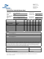
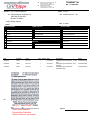


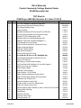

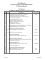
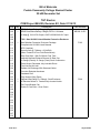


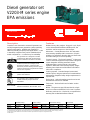
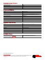
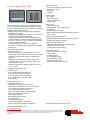


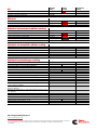
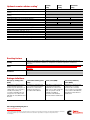
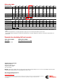

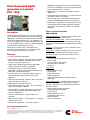

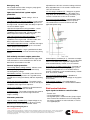


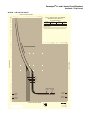
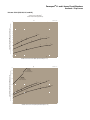


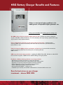
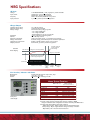
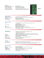
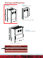

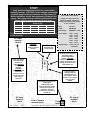
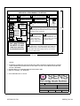

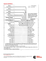

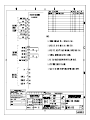

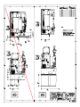

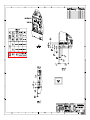

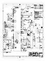

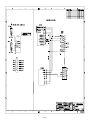

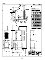


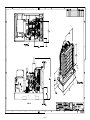


![Forma 900 Series ULT User Manual [EN]](http://vs1.manualzilla.com/store/data/005984153_1-43584ec5392efc31dc54900716e686c7-150x150.png)