1
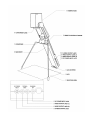
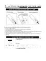
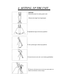
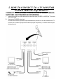
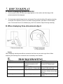
EIKI VISUAL SYSTEM PRESENTER
V-2500
OWNER’S INSTRUCTION MANUAL
EIKI INDUSTRIAL CO., LTD.
WARNING
To reduce the risk of fire or electric shock, do not expose this unit to rain or moisture.
The lighting flash with arrowhead symbol, within an equilateral triangle, is intended to
alert the user to the presence of uninsulated ‘dangerous voltage” within the unit’s
enclosure that may be of sufficient magnitude to constitute a risk of electric shock to
persons.
The exclamation point within an quilateral triangle is intended to alert the user to the
presence of important operating and maintenance (servicing) instructions in the
literature accompanying the unit.
IMPORTANT SAFEGUARDS
1.
Read Instructions - All the safety and operating instructions should be read before the unit is
operated.
2.
Retain Instructions - The safety and operating instructions should be retained for future reference.
3.
Heed Warnings - All warnings on the unit and in the operating instructions should be adhered to.
4.
Follow Instructions - All operating and use instructions should be followed.
5.
Cleaning - Unplug this unit from the wall outlet before cleaning. Do not use liquid cleaners or
aerosol cleaners. Use a damp cloth for cleaning.
6.
Attachments - Do not use attachments not recommended by the unit manufacturer as they may
cause hazards.
7.
Water and Moisture - Do not use this unit near water - for example, near a bath tub, wash bowl,
kitchen sink, or laundry tub: in a wet basement: or near a swimming pool; and the like.
8.
Accessories - Do not place this unit on an unstable can, stand, tripod, bracket, or table. The unit
may fall, causing serious injury to a child or adult, and serious damage to the unit. Use only with a
can, stand, tripod, bracket, or table recommended by the manufacturer’s instructions, and should
use a mounting accessory recommended by the manufacturer.
9.
A unit and ca~ combination should be moved with care. Quick stops, excessive force, and uneven
surfaces may cause the unit and ca~ combination to overturn.
10. Ventilation - Slots and openings in the unit are provided for ventilation and to ensure reliable
operation of the unit and to protect it from overheating, and these openings must not be blocked or
covered. The openings should never be blocked by placing the unit on a bed, sofa, rug, or other
similar surface. This unit should not be placed in a built-in installation such as a bookcase or rack
unless proper ventilation is provided or the manufacturer’s instructions have been adhere to.
11. Power Sources - This unit should be operated only from the type of power source indicated on the
marking label. If you are not sure of the type of power supply to your home, consult your product
dealer or local power company.
12. Grounding polarization - This unit may be equipped with a three-wire grounding-type plug, a play
having a third(grounding) pin. This plug will only fit into a grounding-type power outlet. This is a
safety features. If you are unable to insert the plug into the outlet, contact your electrician to
replace your obsolete outlet. Do not defeat the safety purpose of the grounding-type plug.
13. Power-Cord protection - Power-supply cords should be routed so that they are not likely to be
walked on or pinched by items placed upon or against them, paying particular attention to cords at
plugs, convenience receptacles, and the point where they exit from the unit.
14. Lighting - For added protection for this unit during a lighting storm, or when it is left unattended
and unused for long periods of time, unplug it from the wall outlet and disconnect cable system.
this will prevent damage to the unit due to lighting and power-line surges.
15. Overloading - Do not overload wall outlets, extension cords, or integral convenience receptacles
as this can result in a risk of fire or electric shock.
16. Object and Liquid Entry - Never push objects of any kind into this unit through openings as they
may touch dangerous voltage points or shod-out pads that could result in a fire or electric shock.
Never spill liquid of any kind on the unit.
17. Servicing - Do not attempt to service this unit yourself as opening or removing covers may expose
you to dangerous voltage or other hazards. Refer all servicing to qualified service personnel.
18. Damage Requiring Service - Unplug this unit from the wall outlet and refer
servicing to qualified service personnel under the following conditions.
a) When the power-supply cord or plug is damaged.
b) If liquid has been spilled, or objects have fallen into the unit.
c) If the unit has been exposed to rain or water.
d) If the unit does not operate normally by following the operating instructions, Adjust only these
controls that are covered by the operating instructions as an improper adjustment of other
controls may result in damage and will often require extensive work by a qualified technician
to restore the unit to its normal operation.
e) If the unit has been dropped or damaged in any way.
f) When the unit exhibits a distinct change in performance - this indicates a need for service.
19. Replacement pans - When replacement pans are required, be sure the service technician has used
replacement pans specified by the manufacturer or have the same characteristics as the original
pan. Unauthorized substitutions may result in fire, electric shock, or other hazards.
20. Safety Check - Upon completion of any service or repairs to this unit. ask the service technician to
perform safety checks to determine that the unit is in proper operating condition.
21. Heat - The unit should be situated away from heat sources such as radiators, heat registers, stoves,
or other products(including amplifiers) that produce heat.
SAVE THESE INSTRUCTIONS
TABLE OF CONTENTS
1. DESCRIPTION AND CONTROLS
2-3
2. SETTING-UP REMOTE CONTROL UNIT
4
3. ORERATION OF REMOTE CONTROL
5
4. SETTING-UP THE UNIT
6
5. HOW TO CONNECT TO A TV MONITOR AND EXTERNAL EQUIPMENT
7
6. HOW TO USE AUTO FOCUS
8
7. HOW TO DISPLAY
9
8. TROUBLESHOOTING
9
9. SPECIFICATIONS
10-11
1. DESCRIPTION AND CONTROLS
1. CAMERA HEAD
Rotate to shoot the printed materials and three-dimensional objects in shooting area and to shoot
the distance objects.
2. REMOTE CONTROL STORAGE
Remote control unit works also when seating in the housing.
3. S-VIDEO OUTPUT JACK
Used to connect TV monitor or VCR with S-VIDEO input jack.
4. VIDEO OUTPUT JACK (2)
Used to connect TV monitor or VCR with video input jack.
NOTE : S-VIDEO AND VIDEO signal are output simultaneously and the unit can be connected to
TV monitor with S-VIDEO input jack and VIDEO input jack respectively.
5. DC POWER INPUT JACK
Used to connect DC plug of AC adapter.
6. CONVERSION LENS
Remove this lens to shoot the distance objects.
7. IR RECEIVER
8. MAIN BODY
9. LEG STOPPER
10. LEG
11. SHOOTING AREA
2.
SETTING-UP REMOTE CONTROL UNIT
To insure safe operation, please observe the following precautions
• Use (2) AA type batteries.
• Do not use different type batteries and a new and with a used battery.
• Do not discharge and disassemble a battery.
• Be sure the battery polarity should be set properly and do not contact anode and cathode terminal.
• Remove the batteries from the compartment when the unit is not used.
• If the batteries have leaked on the remote control, carefully wipe the case clean and install new
batteries.
The maximum operating range for the remote control is about 5m, 6Oo
for the front of unit
CAUTION
• Avoid sun light and strong light from the lighting equipment.
• Avoid contact with water.
• Do not drop and give strong impact the remote control unit.
• Avoid heat and humidity.
3.
OPERATION OF REMOTE CONTROL
CAUTION
1. Memory Function
The setting orders are memorized even if the unit is OFF.
Press NORMAL button to restore the setting orders and return to factory preset.
2. When press on the Digital Zoom, Electronic Zoom function operates after 18 times optical
zooming.
4. SETTING- UP THE UNIT
CAUTION
Disconnect power for setting up the unit.
1.Remove two legs from Leg stopper.
2. Spread two legs to the set up position.
3. Lift up the legs to the set up position.
4. Rotate Camera head until Lens is aiming just below.
5. Remove a Remote control unit.(it also works while it is
seated in the Remote control storage.
5. HOW TO CONNECT TO A TV MONITOR
AND EXTERNAL EQUIPMENT
CONNECT THE UNIT AND TV MONITOR WITH VIDEO CABLES
SUPPLIED AS STANDARD ACCESSORIES.
1.
2.
Video output jack of the unit connected to video input jack (S-VIDEO or VIDEO) of TV monitor
with video cable.
How to use S-VIDEO output jack.
S-VIDEO and VIDEO signal are output simultaneously and the unit can be connected to a TV
monitor with S-VIDEO input jack and VIDEO input jack respectively. S-VIDEO cables may be
obtained locally.
6. HOW TO USE AUTO FOCUS
There are three kinds of auto focus mode
1. One-Shot Auto Focus Mode
This mode is to fix the focus just once when an image is set up on screen, so it is proper for the
still material or object.
2. Auto Focus Mode
This mode is to let focusing meet each image, so it is proper for the moving material or when
materials are changed frequently.
3. Electric Focus Mode
This mode is to move lens by FOCUS switch and get focusing.
When FOCUS switch is operated, One-Shot Auto Focus Mode and Auto Focus Mode are
released, and change to Electric Focus Mode.
And if either ZOOM switch or AUTO switch is operated, it changed to One-Shot Auto Focus.
A. One-Shot AUTO Focus
When power on the unit, LED of POSI switch lights, and LED of AUTO lights on and off at the first
setting up. When LED of AUTO goes out, it is ready for One-Shot Auto Focus Mode.
1. When zooming is set up to position, One-Shot Auto Focus works to get focus.
2. When out of focus, push AUTO switch once, and adjust focusing.
B. Change to Auto Focus Mode
1. Pushing AUTO switch about 3 seconds until LED of AUTO switch starts to light on and off, and
stop pushing the switch after LED of AUTO will light. Now Auto Focus works.
2. By pushing buttons other than [POSI/NEGA], Auto Focus mode is canceled.
C. Change to Electric Focus Mode
1. When three-dimensional object with different height is displayed but focus is not obtained properly,
then push FOCUS + or switch to change Electric Focus Mode so as to adjust focusing.
-
2. By pushing buttons other than [ZOOM] or [AUTO], this mode is changed to [One-Shot Auto Focus
mode]
7. HOW TO DISPLAY
A. When displaying printed material.
1,
Connect power of the unit. Blue back image appears on the monitor and then image of the
printed material will be displayed.
2.
Put the printed material below the lens and operate Zoom switch watching TV monitor according
to the size of the material. (if focus is out after zooming operation, push AUTO FOCUS switch
once. If the correct focus is not obtained yet, push Focus switch to adjust focusing manually.)
B. When displaying three-dimensional object.
Caution
When displaying shooting area without conversion lens focus may not work to get focus. When
displaying the shooting area, conversion lens is necessary to be installed.
8.
SYMPTOM
No Power
TROUBLESHOOTING
Focus is Out
CAUSE
Plug not connected to outlet
No good connection of AC
Adaptor
Power is OFF
Poor connection of video cable
Subject is too close to lens
Dark Image
No good Bright adjustment
No Image
REMEDY
Connect plug to outlet
Connect AC Adaptor right
Connect plug to outlet
Connect video cable right
Subject should not come up
more than 100mm above stage
surface
Adjust Brightness by remote
control
9.
SPECIFICATIONS
Lens
shooting Area (*1)
Zooming
Electronic Zooming
Focusing
Iris
TV system
Image pick-up element
All picture element
Effective picture element
f=4.1 —~-73.8mm(F1.4~3.0)÷conversion lens
305 X 225mm (Max.) *1
20 X 15mrn(Min.)
18X)electric power zoom lens
4 X (18 X) optical zoom makes 72 X (Max.)
Auto/One-shot Auto/Power
auto
NTSC
81 8H X 508V
768H X 494V
Synchronization
Horizontal Resolution
S/N ratio
Video output level
White balance
Shutter speed
Nega/Posi reverse
Black & White Mode (*2)
Brightness Adjustment
Image Outline
Adjustment(*2)
Wide picture Right/Left
Reverse
Freeze
Memory function
Default
Input terminal
Output terminal
PAL
1/4 Inch CCD
765H X 596V
752HX582V
Internal
470 TV Lines
460 TV Lines
more than 50dB
C-Video 1.OVp-p/75Ω
S-Video Y=1 .0Vp-p/75Ω
C=0.286Vp-p/75Ω
C=0.300Vp-p/75Ω
Auto / INDOOR /OUTDOOR
1/60 sec
1/50 sec.
(switchable to 1/100 sec)
(switchable to 1/100 sec)
Yes
Yes
Yes
Yes (SOFT~ NORMAL ~ SHARP)
Yes
Yes
Standard
Yes (to reset normal adjustment preset by factory)
DC power input ( EIAJ φ 2.1mm) X 1
Video output (RCA PIN jack/75Ω unbalance)X2
S-Video output (Mini Din 4pm 75Ω unbalance) X 1
Power supply
Power consumption
Dimensions
Weight
Standard accessories
Operation Temperature
Operation Humidity
AC Adaptor DC 6.5V (as standard Acc.)
3.5W
350(W) X 275(D) X 463(H)mm(SET-UP)
130(W) X 500(D) X 85(H)mm(FOLDED)
1.5Kg
Power cord Owners manual, Remote control unit
A/V Cable, prevent dust cover, AC Adaptor X 1
5oC - 40oC
20% - 80% (no condensation)
*1 Shooting area will get a little bit smaller than 305X225mm when monitoring at overscanning.
*2 All functions can be controlled only by the remote control unit.
AUDIO VISUAL/VIDEO PRODUCTS
EIKI INDUSTRIAL CO., LTD.
4-12 Banzai-cho Kita-ku
OSAKA, JAPAN
Tel:6-631 l-9479~Fax:6-63I 1-8486
EIKI INTERNATIONAL, INC.
26794 Vista Terrace Drive,
Lake Forest, CA92630-8 113 U.S.A
Tel: 949-457-0200~ Fax: 949-457-7877
EIKI INTERNATIONAL, INC.CANADA BR.
P.O. BOX 156 310 First Street Unit 2 Midland, Ontario, L4R 4K8 Canada
Tel: 800-563-3454~ Fax: 800-567-4069
EIKI DEUTSCHLAND GmbH
AM Frauwald 1265510 ldstein
Tel:6l26-937l-O~Fax:6l26-937l-l I
EIKI CZECH spol.s.r.o.
Umelecka 15.17000
Praha 7 Holesovice
Tel:2-2057l4l3~Fax:2-2057l4l I