1
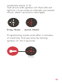
SECURE
powered by
1
To get started with Ride, install the Core
device on your bike using this guide.
When installing modules, refer to the
respective guides.
4
For more info, log on to ridescorpio.com/help
Download the app and sign up for
an account. Then, scan your ID and
activate your subscription account.
Ready to ride.
Log on with the app and Rider Dash
at ridescorpio.com/dash.
5
TABLE OF CONTENTS
7
Components List
8
Plan an Install
9
Mounting
10–11
Switched Power
12
Attach GPS
12
Plug in Core
13–14
Mount the Components
14–16
Encoding the Remote
16
Testing the Installation
18–19
Accelerometer Programming
20–21
Adjusting Perimeter Sensor
22
6
Troubleshooting
COMPONENTS
Remote
Harness
Perimeter
Sensor
Quick
Connector
Hook & Loop /
Cable-ties
Siren
7
PLAN AN INSTALL
Make sure that the motorcycle battery is
fully charged. Verify that no moving parts
will interfere with the components.
Do not route wires near sharp edges
which could cut wires and create a short.
Do not mount components near high heat
sources such as the exhaust pipes. Do not
install the Ride Module under any metal.
The internal antenna can transmit through
fiberglass, leather, or plastic.
TECH TIP
RIDE has an internal cellular
and external GPS antenna.
Do not mount in a location where the
unit will be completely blocked by metal
(such as under the fuel tank).
Ideal locations are under the seat
or in the tail section.
8
MOUNTING
Select a suitable location under the seat
or side cover that the module can lay as
flat as possible.
The Ride Core harness has three wires.
You’ll need to connect these to your bike.
Red: Install the terminal ring of this wire
directly to the battery positive post.
Black: Install the terminal ring of this wire
directly to the battery negative post.
9
SWITCHED POWER
Common tail light power wire colors
Honda
Brown or White w/black stripe
Kawasaki
Red
Suzuki
Brown
Yamaha
Blue w/Red stripe
Harley-Davidson
Blue
Ducati
Yellow
TECH TIP
RIDE requires proper installation of
the switched power wire to function
correctly. Switched power is hot
(12 volts) when the ignition is on, zero
volts when off. Common switched
power sources are the tail light, (NOT
the brake light), the license plate light,
and some accessory plugs.
10
Locate the 12 volt switched wire source
on your vehicle. The most common
applications are the tail light power wire
(not the brake light) or the license plate
light power wire. Do not attach the RIDE
white wire to any LED light sources, LED
lights operate at a lower voltage.
White: Install this wire to a 12 volt
switched source using the provided
Quick Connector.
For example: the tail light or license plate
light power wire.
Remove the cap on the open end of the
Quick Connector attached to the white
wire of the installation harness. Insert
the switched power wire of the vehicle
into the slot in the cap. Tighten the cap
back on to the Quick Connector.
11
ATTACH GPS
Attach the GPS antenna to the RIDE
module. Secure the GPS antenna in a safe
location where it is not blocked by metal
and pointed toward the sky. The antenna
is magnetic, but also secure it with the
included hook & loop/cable ties.
GPS
PLUG IN CORE
Plug the installation harness into the
Ride module. Secure the module with
the included hook & loop/cable ties.
12
TECH TIP
RIDE includes a back-up battery to
protect your bike in case of theft.
The back-up battery will power the
device when disconnected from power.
To disconnect the device without
triggering the battery, unplug the device
within 5 sec of turning on ignition.
1) Turn on the ignition switch.
2) Unplug the main harness
within 5 seconds.
MOUNT THE COMPONENTS
The perimeter sensor uses microwave
technology to detect mass density
movement around the bike. The signal
can transmit through the seat, fiberglass,
leather and plastic, but not metal. Place
this sensor under the seat as close as
possible to the center of the bike.
13
With the hook & loop fasteners, mount
this sensor on top of the battery or any
flat surface, ensuring that the top side of
the sensor is facing upwards. Mount the
perimeter sensor at least 6 inch away
from the unit.
With the provided
hook & loop fasteners,
mount the siren in any
convenient location.
Avoid areas exposed
to heat, road debris
or chemicals.
ENCODING THE REMOTE
Turn the ignition on and immediately
unplug the ride harness from the ride
module within 5 seconds. Plug back in
the Ride harness to the Ride module
with the IGNITION OFF to access remote
programming mode.
14
Within 10 seconds, toggle Ignition On/Off,
On/Off, On/Off.
10 SEC
x3
White light flashes twice every 5 seconds
to indicate Transceiver Programming
mode. Transceiver Programming mode
lasts 3 minutes.
Press and hold button
1 for 10 seconds. When
released, the siren chirps
twice and the red LED
flashes quickly 6 times to
indicate that Ride Core
has learned the code.
The remote echoes
4 chirps and the LCD
displays [LErn donE] to
confirm it is encoded.
15
If you are encoding a second remote
repeat the previous step for the second
transceiver before continuing. Ignition
On/Off exits Remote Programming mode.
TESTING THE INSTALLATION
Once the harness is plugged in confirm
that there are lights illuminated on the
Ride module to confirm you have good
power and ground.
Turn the ignition switch of the motorcycle
to the “on” position. Confirm that a
red light is now illuminated solid on the
Ride module.
Turn the ignition switch to the “off”
position. Confirm the red light is
now blinking.
16
TECH TIP
If the Red light and White light do not
stay on solid when the ignition is on then
there is a problem with the switched
power (white wire) installation. Consult
the service manual and/or the wiring
diagram of the motorcycle to confirm
you have chosen the correct switched
power source wire.
17
ACCELEROMETER
PROGRAMING
After the installation is complete
and tested, turn the ignition on and
immediately unplug the ride harness
from the ride module within 5 seconds.
Plug back in the Ride harness to the Ride
module with the IGNITION ON to access
Accelerometer Programming mode.
During first 10 seconds the white LED will
blink slowly to indicate countdown.
10 SEC
Turn Ignition Off within 10 seconds.
If no action taken in 10 seconds, Red light
then stays on to indicate Ignition On.
White light flashes every 3 seconds to
indicate programming mode.
Red light flashes to indicate
accelerometer sensitivity setting.
Turn Ignition on/off to toggle through
18
sensitivity levels. (1-5).
Test shock with ignition off. Red LED will
light for 1.5 seconds to indicate successful
shock. Wait 1 second to test again.
Prog. Mode
Accel. Mode
Programming mode ends after 2 minutes
of inactivity. Exit any time by turning
ignition on for 3 seconds.
1.5 sec
19
ADJUSTING
PERIMETER SENSOR
Although the sensor is pre-set from the
factory it may be necessary to adjust the
sensitivity to suit your specific application.
Walk towards the motorcycle and try and
lean over the top of it. Once the sensor
detects movement the siren will begin to
chirp slowly.
If you back away from the motorcycle the
siren will stop chirping. If you continue to
move closer to the motorcycle the siren
will start to chirp faster and faster and
then go into a full alarm.
20
Sensitivity can be adjusted by removing
the plastic cap and tuning the adjustment
screw. To increase sensitivity, turn
adjustment screw clockwise. To decrease
sensitivity, turn the adjustment screw
counter clockwise.
Less
Sensitivity
More
Sensitivity
TECH TIP
Do not turn sensitivity above half way,
this may cause false alarms.
21
TROUBLESHOOTING
Lights not appearing when Ride is plugged
in: Check that the power and ground
wires have a firm connection to the
appropriate battery posts. Also verify that
your battery is fully charged.
Red light not appearing when the key is
on: Check that the white wire is firmly
connected to a 12v switch source.
For example: When the key is turned on,
the wire needs 12 volts, when the key is
turned off it will get zero volts.
Still having issues? Visit our online support:
www.ridescorpio.com/help
[email protected]
or call our Technical Support:
US: 1 800 428 0440
INT: +1 480 951 1109
Mon-Fri, 8 a.m. to 5 p.m. MST
22
24