1
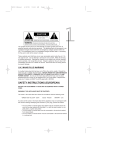
Owner’s Manual
SR Series Equalizers
• SR 231QX
• SR 430QX
• SR 431QX
• SR 830QX
• SR 831QX
A Harman International Company
Warning
For your protection, please read the following:
Water and Moisture: Appliances should not be used near water
(e.g. near a bathtub, washbowl, kitchen sink, laundry tub, in a wet
basement, or near a swimming pool, etc.) Care should be taken so
that objects do not fall and liquids are not spilled into the enclosure
through openings.
These symbols are internationally accepted symbols that warn of potential
hazards with electrical products.The lightning flash means that there are
dangerous voltages present within the unit.The exclamation point indicates
that it is necessary for the user to refer to the owners manual.
These symbols warn that there are no user serviceable parts inside the unit.
Do not open the unit. Do not attempt to service the unit yourself. Refer all
servicing to qualified personnel. Opening the chassis for any reason will void
the manufacturer’s warranty. Do not get the unit wet. If liquid is spilled on
the unit, shut it off immediately and take it to a dealer for service.
Disconnect the unit during storms to prevent damage.
U.K. Mains Plug Warning
A molded mains plug that has been cut off from the cord is unsafe.
Discard the mains plug at a suitable facility. Never under any circumstances should you insert a damaged or cut mains plug into a 13
amp power socket. Do not use the mains plug without the fuse cover
in place. Replacement fuse covers can be obtained from your local retailer. Replacement fuses are 13 amps and MUST be ASTA approved to
BS1362.
Power Sources: The appliance should be connected to a power
supply only of the type described in the operating instructions or as
marked on the appliance.
Grounding or Polarization: Precautions should be taken so that
the grounding or polarization means of an appliance is not defeated.
Power Cord Protection: Power supply cords should be routed so
that they are not likely to be walked on or pinched by items placed
upon or against them, paying particular attention to cords at plugs,
convenience receptacles, and the point where they exit from the
appliance.
Servicing: To reduce the risk of fire or electrical shock, the user
should not attempt to service the appliance beyond that described in
the operating instructions. All other servicing should be referred to
qualified service personnel.
For units equipped with externally accessible fuse receptacle: Replace fuse with same type and rating only.
Safety Instructions
Electromagnetic Compatibility
Notice for customers if your unit is equipped with a power cord.
Operation is subject to the following conditions:
•This device may not cause harmful interference.
•This device must accept any interference received, including
interference that may cause undesired operation.
•Use only shielded interconnecting cables.
•Operation of this unit within significant electromagnetic fields
should be avoided.
Warning:This appliance must be earthed.
The cores in the mains lead are colored in accordance with the following
code:
Green and Yellow - Earth Blue - Neutral
Brown - Live
As colors of the cores in the mains lead of this appliance may not correspond with the colored markings identifying the terminals in your plug, proceed as follows:
•The core which is colored green and yellow must be connected to the
terminal in the plug marked with the letter E, or with the earth symbol, or colored green, or green and yellow.
•The core which is colored blue must be connected to the terminal
marked N, or colored black.
•The core which is colored brown must be connected to the terminal
marked L, or colored red.
This equipment may require the use of a different line cord, attachment
plug, or both, depending on the available power source at installation. If the
attachment plug needs to be changed, refer servicing to qualified service
personnel who should refer to the table below.The green/yellow wire shall
be connected directly to the unit’s chassis.
CONDUCTOR
L
LIVE
WIRE COLOR
Normal
Alt
BROWN
BLACK
N
NEUTRAL
BLUE
WHITE
E
EARTH GND
GREEN/YEL
GREEN
Warning: If the ground plug is defeated, certain fault conditions in the unit
or in the system to which it is connected can result in full line voltage
between chassis and earth ground. Severe injury or death can then result if
the chassis and earth ground are touched simultaneously.
SR Series EQ’s
The symbols shown above are internationally accepted symbols that warn of
potential hazards with electrical products. The lightning flash with arrowpoint
in an equilateral triangle means that there are dangerous voltages present within the unit. The exclamation point in an equilateral triangle indicates that it is
necessary for the user to refer to the owner’s manual.
These symbols warn that there are no user serviceable parts inside the unit.
Do not open the unit. Do not attempt to service the unit yourself. Refer all
servicing to qualified personnel. Opening the chassis for any reason will void
the manufacturer’s warranty. Do not get the unit wet. If liquid is spilled on the
unit, shut it off immediately and take it to a dealer for service. Disconnect the
unit during storms to prevent damage.
U.K. MAINS PLUG WARNING
A molded mains plug that has been cut off from the cord is unsafe. Discard
the mains plug at a suitable disposal facility. NEVER UNDER ANY CIRCUMSTANCES SHOULD YOU INSERT A DAMAGED OR CUT MAINS PLUG
INTO A 13 AMP POWER SOCKET. Do not use the mains plug without the
fuse cover in place. Replacement fuse covers can be obtained from your local
retailer. Replacement fuses are 13 amps and MUST be ASTA approved to
BS1362.
Safety Instructions (European)
Notice For Customers If Your Unit Is Equipped With A Power Cord.
WARNING: THIS APPLIANCE MUST BE EARTHED.
The cores in the mains lead are colored in accordance with the following
code:
GREEN and YELLOW - Earth
BLUE - Neutral
BROWN - Live
As colors of the cores in the mains lead of this appliance may not correspond
with the colored markings identifying the terminals in your plug, proceed as
follows:
• The core which is colored green and yellow must be connected to the
terminal in the plug marked with the letter E, or with the earth symbol,
or colored green, or green and yellow.
1
2
SR Series EQ’s
• The core which is colored blue must be connected to the terminal
marked N or colored black.
• The core which is colored brown must be connected to the terminal
marked L or colored red.
These units comply with the European “EMC Directive” for emissions and susceptibility.
The power cord is terminated in a CEE7/7 plug (Continental Europe). The
green/yellow wire is connected directly to the unit's chassis. If you need to
change the plug, and if you are qualified to do so, refer to the table below.
CONDUCTOR
WIRE COLOR
Normal
Alt
L
LIVE
BROWN
BLACK
N
NEUTRAL
BLUE
WHITE
E
EARTH GND
GREEN/YEL
GREEN
WARNING: If the ground is defeated, certain fault conditions in the unit or in
the system to which it is connected can result in full line voltage between
chassis and earth ground. Severe injury or death can then result if the chassis
and earth ground are touched simultaneously.
IMPORTANT! FOR YOUR PROTECTION, PLEASE READ
THE FOLLOWING:
Water and Moisture: Appliance should not be used near water (e.g. near a
bathtub, washbowl, kitchen sink, laundry tub, in a wet basement, or near a
swimming pool, etc). Care should be taken so that objects do not fall and liquids are not spilled into the enclosure through openings.
POWER SOURCES:The appliance should be connected to a power supply only
of the type described in the operating instructions or as marked on the appliance.
GROUNDING OR POLARIZATION: Precautions should be taken so that the
grounding or polarization means of an appliance is not defeated.
POWER CORD PROTECTION: Power supply cords should be routed so that
they are not likely to be walked on or pinched by items placed upon or against
them, paying particular attention to cords at plugs, convenience receptacles,
and the point where they exit from the appliance.
SERVICING:The user should not attempt to service the appliance beyond that
described in the operating instructions. All other servicing should be referred
to qualified service personnel.
SR Series EQ’s
INTRODUCTION
Congratulations, and thank you for your purchase of DOD equalization components. DOD equalizers are versatile, cost-effective equalization tools for the
musician, performer, studio engineer, and sound contractor. Each equalizer allows
the user to see a graphic representation of the equalization applied to the audio
spectrum, and offers the flexibility to provide solutions to many EQ problems.
The units offer up to 12 dB of cut or boost per band with a switchable low cut
filter for each channel. Electronic switching of these functions minimizes switching transients (loud pops or clicks when the switch is depressed), and up to ±12
dB of level control is available to compensate for gain changes due to equalization. This feature makes A/B comparisons of the equalized signal to the original
signal quick and easy. Connection to the equalizer may be either balanced with
an XLR connector or with optional unbalanced 1/4" phone plug making the
units readily interfaceable to any system. Dual channel units may be used as a
stereo equalizer or as two independent equalizers. The units offer either 1/3rd
octave or 2/3rds octave resolution, depending on the unit chosen. All DOD
equalizers are solidly built with steel chassis and CSA standard circuit boards for
years of reliable service.
WHY A 1/3RD OCTAVE OR A 2/3RD OCTAVE EQUALIZER?
Most graphic equalizers divide up the audio frequency range into 1/3rd octave
or 2/3rds octave pieces. One octave covers a 2-to-1 range of frequencies. For
example, the frequency range form 50 to 100 Hertz is one octave. The audio
frequency range covers 10 octaves from 20 Hz to 20 kilo (thousand) Hz. If each
of the ten octaves is divided into thirds, you get 30 pieces, or bands, of frequency. (The 31 bands on DOD equalizers result from including both 20 Hz and 20
kHz bands on the ends of the audio frequency range). A 1/3 octave equalizer
means that 3 bands span 1 octave, while a 2/3 octave equalizer means that 3
bands span 2 octaves. Therefore, one band on a 2/3 octave equalizer is twice as
wide as one band on a 1/3 octave equalizer. So, boosting or cutting any band will
affect a wider range of frequencies on the 2/3 octave equalizer.
A 1/3rd octave equalizer is the most precise because you're working with a narrower frequency range per band or slider on the equalizer. To cover the entire
audio range, you need 31 bands or sliders, which normally take up the entire
width of a rack panel, and take some time to adjust properly. A high-resolution
real time audio spectrum analyzer (such as DOD's SR Series RTA ) is a very useful tool when setting up a 1/3rd octave graphic equalizer to compensate for poor
room acoustics, poor speaker response, or the deficiencies of an audio system.
While the 2/3rds octave is not as precise as a 1/3rd, it takes far less time to
equalize a signal with this unit, and allows more channels of EQ to be reached.
The 2/3rds octave EQ allows you to quickly and easily modify a sound for use in
music, recording, or sound reinforcement.
3
4
SR Series EQ’s
DOD graphic equalizers offer both 1/3rd and 2/3rds octave models in stereo and
1/3 octave models in mono to meet any need.
INSTALLATION
Install the equalizer in a rack with the provided rack screws. Route the AC
power cord to a convenient power outlet away from audio lines. The unit may
be turned on and off using the front panel power switch. Since the units draw a
relatively small amount of current during idle, they can be left on continuously.
DOD equalizers generate very little heat during operation and thus do not need
to be specially ventilated or cooled. The units should not, however, be subjected to high temperatures for extended periods. Although the unit's chassis is
shielded against radio frequency and electromagnetic interference, extremely
high RF and EMI fields should be avoided.
The XLR inputs and outputs are for balanced connections. Only the 1/4" phone
plug inputs and outputs can be used for unbalanced connections. Use only one
input/output connector pair at a time. Using more than one input/output connector pair at a time can unbalance balanced lines, cause phase cancellation,
short a conductor to ground, or cause damage to other equipment connected
to the equalizer.
FOR BALANCED 1/4 “ TRS PHONE PLUG CONNECTION - Wire the connectors as follows:
Phone Plug
Connection
tip
ring
sleeve
: high
: low
: ground
FOR 1/4" MONO PHONE PLUG CONNECTION:
Phone plugConnection
tip
: high
sleeve
: ground
XLR CONNECTORS - XLR type connectors are wired as follows:
XLR
Balanced
Unbalanced
Connector
Connection
Connection
pin 1:
pin 2:
pin 3:
ground
high
low
ground
high or hot
ground
Once the graphic equalizer has been installed and adjusted for the required
equalization and level, an optional security panel can be installed to keep unauthorized persons from changing settings.
SR Series EQ’s
APPLICATIONS
DOD graphic equalizers can be used wherever modification of the frequency
contour of a sound or sound system is needed. A graphic equalizer offers a
solution to many common sound problems, both large and small. Also, creative
experimentation on the part of the user can produce some nice results.
SOUND REINFORCEMENT APPLICATIONS
By routing the signal from the mixer to the SR Equalizer, and then to the main
power amplifiers (or crossover), the overall frequency of the mix can be altered
to do a number of things.
A. Using a real time audio spectrum analyzer (such as DOD's SR Series RTA), a
calibrated microphone, and a pink noise generator, the audio system can be
tuned to make the overall audio spectrum response of the sound system and the
room environment equal in frequency response.
B. Greater gain-before-feedback characteristics can be achieved by turning up
the sound system to the feedback point and attenuating the oscillating (ringing)
frequency. 1/3rd octave resolution is best for this application. Turn the system
up to feedback again and attenuate the second oscillating frequency. Repeat the
process again for the third oscillating frequency.
C. Protection of amplifiers and speakers can be accomplished using the LOW
CUT feature of the equalizer. Wind noise or sub sonic frequencies can cause
damage to the amps and/or speakers. However, by rolling off the extreme low
frequencies, a measure of protection is added to the system without severely
affecting the overall sound quality.
D. In noisy environments, the audio signal can be tailored for better intelligibility and penetration. This is particularly useful for paging systems.
E. Creative use of the equalizer allows shaping of the signal for a more pleasing
sound or for special effects. The only limits are those of taste and imagination.
5
6
SR Series EQ’s
MUSICAL INSTRUMENT APPLICATIONS
A. Putting an equalizer in line with a musical instrument allows you to modify
the sound of the instrument. You can brighten the sound, add body to a thin
sounding instrument, or you can give the sound a totally different character.
B. An equalizer allows you to eliminate unwanted sounds, such as the 60 cycle
hum from a badly grounded sound source.
STUDIO APPLICATIONS
A graphic equalizer is one of the most useful tools in the sound engineer's bag.
DOD equalizers offer the features and the flexibility to deliver uncompromising
quality in the studio.
A. Fix a track that doesn't sound quite right. Put the equalizer in a channel
insert.
B. Create an artificial stereo image by splitting a monaural signal and equalizing
the split signals differently. Pan one signal to the right and the equalized signal to
the left.
C. Shape the sound by changing the frequency response of the track.
D. Special effects like telephone sounds are done by cutting off the low end at
200 Hz and the high end at 6 kHz.
Also, when used with other pieces of equipment, you can do some real signal
processing magic. Emphasizing the high frequencies of a signal and feeding the
modified signal to the side chain of a compressor creates a de-essing effect. By
emphasizing the low frequencies and feeding the signal to the side chain creates
a de-thumper. You can also reduce unwanted frequency-dependent noise in a signal by cutting the offending frequencies with an equalizer and letting a noise gate
"key" on the modified signal while letting the original signal pass, gating the
unwanted sounds.
SR Series EQ’s
OPERATION
FRONT PANEL FUNCTIONS DESCRIPTION
POWER SWITCH: Turns the power to the equalizer on or off.
EQUALIZER SLIDERS: Each one of these linear potentiometers will boost
or cut its noted frequency by +/- 12 dB. When all the sliders are in the center
detented position, the output of the equalizer is said to be flat. The numbers
marked over the top of each slider represent the center frequency that each
band will control.
INPUT LEVEL CONTROL: This control sets the signal level to the equalizer. It is capable of +/- 12 dB of gain. The level is indicated on the INPUT LEVEL
BAR GRAPH. This control is used to compensate for variations in volume due
to gain changes caused by equalizing individual frequencies.
LOW CUT FILTER SWITCH: This switch electronically inserts a filter into
the signal path, which cuts the low frequencies at 12 dB per octave (-3dB @50
Hz). The LED indicator lights when the switch is depressed and the filter is in
the circuit.
IN/OUT BYPASS SWITCH: This switch inserts or removes the equalizer
channel from the signal path. An LED indicator lights when the switch is
depressed and the equalizer channel is in the circuit path. The bypass function is
FET switched to prevent switching transients when inserting the equalizer into
the circuit.
LED LEVEL INDICATOR: The LED level indicator shows the signal level to
the unit.
REAR PANEL FUNCTIONS
BALANCED INPUT: Accepts a standard XLR type connector [see section
on installation for wiring connections].The 1/4” phono jack may also be used for
balanced inputs when used with a TRS connector. Maximum allowable input level
is +18 dBu. Input impedance for a balanced connection is 80 kOhms.
UNBALANCED INPUT: Accepts an1/4” plug (see section on installation for
wiring connections). Connections are unbalanced. Maximum allowable input is
+18 dBu. Input impedance for the unbalanced connection is 40Ω.
BALANCED OUTPUT:Accepts a standard XLR type connector [see section
on installation for wiring connections]. A 1/4" TRS jack may be used to achieve
an impedance balanced output. Maximum balanced output level is +21 dBu.
Balanced output impedance is 102 Ω.
UNBALANCED OUTPUT: Accepts a 1/4” plug (see section on installation
for wiring connections). Connections are unbalanced. Maximum unbalanced
output level is +21 dBu. Output impedance is 51 Ω unbalanced.
7
8
SR Series EQ’s
ATTENTION: DO NOT USE BOTH THE BALANCED AND UNBALANCED
INPUT/OUTPUT JACKS TO A CHANNEL AT THE SAME TIME. Using more
than one connector at a time for the input/output pair can unbalance balanced
lines, cause phase cancellation, short a conductor to ground, or cause damage to
other equipment connected to the equalizer.
Maintenance and service
Other than keeping the unit clean and occasionally checking the connectors and
cables to the unit for integrity, there is no maintenance necessary for DOD
equalizers.
There are NO user serviceable parts inside the units. Opening the chassis will
void the warranty. All service and repair must be performed by the factory or
an authorized service center for the warranty to remain in service.
Should a problem arise with the equalizer, please contact your authorized DOD
Electronics dealer for return/repair procedures.
Specifications
Frequency Response: 20Hz to 20kHz, =0/-0.5 dB
Low Cut Filter: 12 dB/ octave roll-off, 3 dB down at 50 Hz switchable in or out.
Frequency Center Tolerance: 5%
Control Range: 12 dB cut/ boost
Recommended Operating Level: -10 dBV to +4 dBu
Input Impedance: 40k Ω balanced, 20k Ω unbalanced
Maximum Output Level: +21 dBu (balanced or unbalanced)
Input Level Control: +/-12 dB
Input Level Indicator: LED bar graph; -10,0,+10, and +17
Harmonic Distortion: .006% @ 1 kHz
S/N Ratio: Greater than 90 dB (ref. 0.0775Vrms)
Electronic Switching: In/Out and Filter switches (FET type)
Power Requirements: 100/120/220-230/240 VAC, 50/60 Hz @ 18 watts
Dimensions 430 and 431: 1.75”x6”x19”
Dimensions 231, 830, and 831: 3.5”x6”x19”
SR Series EQ’s
DOD WARRANTY
1. The warranty registration card must be mailed within ten days after purchase
date to validate this warranty.
2. DOD warrants this product, when used solely within the U.S., to be free from
defects in material and workmanship under normal use and service.
3. DOD Electronics liability under this warranty is limited to repairing or replacing defective materials that show evidence of defect, provided the product is
returned through the original dealer, where all parts and labor will be covered
up to a period of three (3) years. The company shall not be responsible for any
consequential damage as a result of the products use in any circuit or assembly.
4. Proof of date of purchase is considered to be the burden of the consumer.
5. DOD reserves the right to make changes in design or make improvements
upon this product without incurring any obligation to install the same on PRODUCTS PREVIOUSLY MANUFACTURED.
6. The foregoing is in lieu of all other warranties, either expressed or implied,
and DOD neither assumes nor authorizes any person to assume for it any obligation or liability in connection with the sale of this product. In no event shall
DOD or its dealers be liable for special or consequential damages or from any
delay in the performance of this warranty due to causes beyond their control.
9
10
SR Series EQ’s
SR 430QX
SR 431QX
SR 830QX
SR 831QX
SR 231QX
DECLARATION OF CONFORMITY
Manufacturer’s Name:
DOD Electronics Corporation
Manufacturer’s Address:
8760 S. Sandy Parkway
Sandy, Utah 84070, USA
declares that the products:
Product Name:
SR Series Equalizers
Product Options:
All
conform to the following product specifications:
Safety:
EN 60065 (1993)
IEC65 (1985) with Amendments 1,2,3
EMC:
EN 55013 (1990)
EN 55020 (1991)
Supplementary Information:
The products herewith comply with the requirements
of the Low Voltage Directive 73/23/EEC and the EMC
Directive 89/336/EEC as amended by directive
93/68/EEC.
DOD Electronics Corporation
President of DOD
8760 S. Sandy Parkway
Sandy, Utah 84070, USA
Effective: 11/24/97
European Contact: Your Local DOD Sales and Service Office or
International Sales Office
8760 S. Sandy Parkway
Sandy, Utah 84070, USA
Tel (801) 568-7638
Fax (801) 568-7642
V ISIT DOD E LECTRONICS ON THE WORLD W IDE W EB
HTTP :// WWW. DOD. COM
AT
DOD E LECTRONICS C ORPORATION
8760 S OUTH S ANDY PARKWAY
S ANDY, U TAH 84070
T ELEPHONE 801-566-8800
FAX 801-566-7005
I NTERNATIONAL D ISTRIBUTION
8760 S OUTH S ANDY PARKWAY
S ANDY, U TAH 84070
T ELEPHONE 801-568-7638
FAX 801-568-7642
DOD
IS A
R EGISTERED T RADEMARK
OF
H ARMAN M USIC G ROUP I NC .
© 1998 DOD E LECTRONICS C ORPORATION
DOD 18-2160-C