1
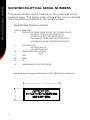
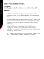
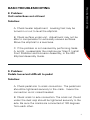
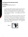
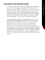
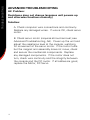
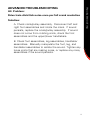
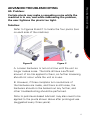
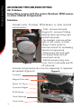
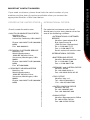
Do not print this page
©2006. Nautilus, Inc. All Rights Reserved. Schwinn is a registered trademark. Nautilus, Inc., World Headquarters, 16400 SE Nautilus Dr., Vancouver, WA 98683
SCHWINN RETAIL ELLIPTICALS
Service Manual
This manual applies to the following models:
426
430 431
450
PN 001-6987 Rev B (03/07)
SERVICE MANUAL
CONTENTS
Table of Contents
Reading the Serial Number ................................................2
Troubleshooting ..................................................................3
Important Contact Numbers ..............................................16
reading the serial number
Schwinn Elliptical Serial Numbers
The serial number can be located on the underside of the
machine base. The below instructions show how to decode
the information contained in the serial number:
Serial Number Scheme as Follows:
AAAAAA: KIT NUMBER MODEL
CC:
COUNTRY CODE (ELECTRONIC REFERENCE DOES NOT APPLY TO STRENGTH PRODUCTS)
00-DOMESTIC, 110V, 60 HZ, US UNITS ENGLISH OVERLAYS
01-DOMESTIC, 220V, 60HZ, US UNITS ENGLISH OVERLAYS
02-INTERNATIONAL, 230V, 50HZ, METRIC UNITS ENGLISH OVERLAYS
03-INTERNATIONAL, 230V, 50HZ, METRIC UNITS GERMAN OVERLAYS
H
CONTACT HEART RATE
0-NO CONTACT HEART RATE
3-WITH CONTACT HEART RATE
XXX
MANUFACTURER/VENDOR (3 DIGIT CODE)
SRS-SRS
YY
YEAR
MM
MONTH
DD
DAY
ZZZ
MACHINE NUMBER BUILT THAT PRODUCTION RUN
Example serial number (Domestic 110V 430 Elliptical shown):
56
21
TROUBLESHOOTING
BASIC Troubleshooting
1. Problem:
No display/partial display/unit will not turn on
Solution:
A. Make sure the unit is plugged into a functioning wall
outlet.
B. Check the power connection at the front of the unit.
Connection should be secure and undamaged. Replace
the unit adapter or connection if either are damaged.
C. Check data cable integrity. All cable wires should
be intact. If any are visibly crimped or cut, replace the
cable.
D. Check data cable connections/orientation. Insure the
cable is connected securely and oriented properly. The
small latch on the connector should line up and snap
into place.
E. Check console display for damage. Check for
any visual sign that the console display is cracked or
otherwise damaged. Replace the console if damaged.
F. Check console display. If the console only has a
partial display and all connections are OK, replace the
computer.
Advanced Troubleshooting
If any steps above do not resolve problems, proceed to
ADVANCED TROUBLESHOOTING, problem A1.
TROUBLESHOOTING
BASIC Troubleshooting
2. Problem:
Unit operates but Contact HR not displayed
Solution:
Note: Sensors may have difficulty with dried out or
calloused hands. A conductive electrode cream such as
“Signa Crème” or “Buh-Bump” can help make better
conduct. These are available on the Web or at medical
or some larger fitness stores.
A. Insure hands are centered on the HR sensors.
Hands must be kept still with relatively equal pressure
applied to each side.
B. Check the HR cable connection at the console.
Insure the cable is connected securely to console.
If the above tests reveal no problems, replace
the console handle assembly.
3. Problem:
Unit operates but Telemetric HR not displayed
Solution:
A. Check for interference. Try moving the unit away
from sources of interference (TV, Microwave, etc.). If
interference is eliminated and HR still does not function,
replace the strap. If the problem persists, replace the
console.
4. Problem:
Console displays “E2” error code
Solution:
A. Check data cable integrity. All wires in the cable
should be intact. If any are crimped or cut, replace the
cable.
B. Check data cable connections/orientation. Insure the
cable is connected securely and oriented properly. The
small latch on the connector should line up and snap
into place.
If the above tests reveal no problems, Motor,
DC Servo should be replaced.
TROUBLESHOOTING
BASIC Troubleshooting
TROUBLESHOOTING
BASIC Troubleshooting
5. Problem:
No speed/RPM reading
Solution:
A. Check data cable integrity. All wires in the cable
should be intact. If any are crimped or cut, replace the
cable.
B. Check data cable connections/orientation. Insure the
cable is connected securely and oriented properly. The
small latch on connector should line up and snap into
place.
C. Check magnet position (requires shroud removal;
see Advanced Troubleshooting, A6). The magnet should
be in place on the flywheel. If no magnet is present,
replace the flywheel magnet.
D. Check RPM Sensor (requires shroud removal; see
Advanced Troubleshooting, A6). The RPM sensor
should be aligned with the magnet and connected
to the data cable. Re-align the sensor if necessary;
replace if there is any damage to the sensor or to the
connecting wire.
TROUBLESHOOTING
BASIC Troubleshooting
6. Problem:
Console shuts off (enters sleep mode) while in use
Solution:
A. Check data cable integrity. All cable wires should be
intact. If any are crimped or cut, replace the cable.
B. Check data cable connections/orientation. Insure the
cable is connected securely and oriented properly. The
small latch on the connector should line up and snap
into place.
C. Reset Machine (if equipped with reset button).
Unplug the unit from the electrical outlet for three
minutes. Reconnect to the outlet, and after the console
powers up, press “reset”.
D. Check magnet position (requires shroud removal;
see Advanced Troubleshooting, A6). The magnet should
be in place on the flywheel. If no magnet is present,
replace the flywheel magnet.
E. Check RPM Sensor (requires shroud removal; see
Advanced Troubleshooting, A6). The RPM sensor
should be aligned with the magnet and connected
to the data cable. Re-align the sensor if necessary;
replace if there is any damage to the sensor or to the
connecting wire.
TROUBLESHOOTING
BASIC Troubleshooting
7. Problem:
Fan (if equipped) will not turn on or will not turn off
Solution:
A. Check data cable integrity. All wires in the cable
should be intact. If any are crimped or cut, replace the
cable.
B. Check data cable connections/orientation. Insure the
cable is connected securely and oriented properly. The
small latch on the connector should line up and snap
into place.
C. Reset Machine (if equipped with reset button).
Unplug the unit from the electrical outlet for three
minutes. Reconnect to the outlet, and after the console
powers up, press “reset”.
D. If the fan still does not function properly, replace the
fan. If the problem persists, replace the console.
TROUBLESHOOTING
Basic Troubleshooting
8. Problem:
Unit rocks/does not sit level
Solution:
A. Check leveler adjustment. Leveling feet may be
turned in or out to level the elliptical.
B. Check surface under unit. Adjustment may not be
able to compensate for extremely uneven surfaces.
Move the elliptical to a level area.
C. If the problem is not resolved by performing tasks
A. and B., re-assemble the machine per Step 2, Install
Front Stabilizer and Extrusion Assembly, in the 430
Elliptical Assembly Guide.
9. Problem:
Pedals loose/unit difficult to pedal
Solution:
A. Check pedal arm to crank connection. The pedal arm
should be tightened securely to the crank. Insure the
connection is not cross-threaded.
B. Check crank to axle connection. The crank nut (found
under the dust cap) should be tightened securely to the
axle. Be sure the cranks are connected at 180 degrees
from each other.
TROUBLESHOOTING
advanced Troubleshooting
A1. Problem:
No display/Unit will not turn on
Solution:
A. Check A/C adapter (assumes electrical outlet is OK).
Use a volt meter to check the voltage output from the
adapter. With the positive lead on the inside of the
connector and negative lead on the outside, voltage
should be within 9-14VDC. If the voltage is outside this
range, replace the adapter. If the voltage is OK, check
the computer.
B. Check computer (assumes A/C adapter output is OK).
Disconnect the upper wiring harness from the back of
the computer. While power is supplied to the machine,
use a volt meter to check that voltage is reaching the
computer. Voltage between pins 1 (purple) and 3 (pink),
(Figure A), should be within 9-14VDC. If the voltage is
within range, replace the computer. If not, replace the
upper wiring harness.
Figure A
10
TROUBLESHOOTING
advanced Troubleshooting
C. Check upper wiring harness (assumes A/C adapter
is OK, and no voltage is present at the end of the
upper wiring harness). Remove the console mast and
disconnect the upper wiring harness from the lower
wiring harness. Test the output voltage at the lower
harness using pins 1 and 3, as above. If the voltage is
present is now between 9-14VDC, replace the upper
wiring harness. If not, check the power plug wire.
D. Check power plug wire (requires shroud removal;
see Advanced Troubleshooting, A6). Note, this step
assumes the AC Adapter is OK, and no voltage is
present at the end of the lower wiring harness).
Remove the shroud half that has the power plug
mounted into it. Disconnect the power plug wire from
the resistance motor wiring harness. Test the voltage
output of the power plug wire. If no voltage is present,
replace the power plug wire. If the voltage is within
9-14VDC, replace the Motor, DC Servo (includes lower
wiring).
11
TROUBLESHOOTING
advanced Troubleshooting
A2. Problem:
Resistance does not change (assumes unit powers up
and otherwise functions normally)
Solution:
A. Check computer wire connections and continuity.
Replace any damaged wires. If wire is OK, check servo
motor.
B. Check servo motor (requires shroud removal; see
Advanced Troubleshooting, A6). Power up the unit and
adjust the resistance level at the console, watching
for movement at the servo motor. If the motor turns
but the magnet arm assembly does not move, check
and secure the mechanical components. Replace
any damaged components. If the motor does not
turn, check wire continuity and the integrity between
the console and the DC motor. If all cables are good,
replace the Motor, DC Servo.
12
A3. Problem:
Drive train click/tick noise once per full crank revolution
Solution:
A. Check crank/pulley assembly. Disconnect left and
right foot assemblies and rotate the crank. If sound
persists, replace the crank/pulley assembly. If sound
does not come from rotating crank, check the foot
assemblies and the upper/lower handlebars.
B. Check foot assemblies, leg assemblies, handlebar
assemblies. Manually manipulate the foot, leg, and
handlebar assemblies to isolate the sound. Tighten any
loose joints that are making noise, or replace any noisy
assemblies if the sound persists.
13
TROUBLESHOOTING
advanced Troubleshooting
TROUBLESHOOTING
advanced Troubleshooting
A4. Problem:
Noise multiple times per revolution or once per 1.5 revolution.
Solution:
A. Check belt. Remove shrouds (see A6). Visually
inspect the belt for irregularity while slowly rotating the
pedals. Replace the belt if damaged.
B. Check tensioner spring, pulley. Check that the
belt tensioner spring is in place and functional. If the
tensioner is in place but is not providing enough tension
to prevent the belt from slipping, adjust or replace the
tension spring.
C. Check flywheel assembly. Slowly rotate the crank
arms and listen closely for any sound from the flywheel
hub. If sound is present, replace the flywheel bearings.
14
TROUBLESHOOTING
advanced Troubleshooting
A5. Problem:
Certain pivots may make a squeaking noise while the
machine is in use, and while addressing the problem,
the user tightens the pivots too tight.
Solution:
Refer to Figures B and C to locate the four pivots (two
on each side of the machine).
Figure B
Figure C
A. Loosen hardware ¼ turn at a time until the unit no
longer makes noise. The bolts all have a sufficient
amount of loc-tite applied to them, so further loosening
should not occur while the unit is in use.
B. However, if three complete turn revolutions of
the hardware are made, and there is still noise, the
hardware should not be backed out any further, and
other troubleshooting should be performed.
Note: A petroleum-based lubricant may also need to be
applied to the pivots shown above after prolonged use
(suggested every three years).
15
TROUBLESHOOTING
advanced Troubleshooting
A6. Problem:
Something wrong with the motor, flywheel, RPM sensor,
or other internal components
Solution:
Access motor, flywheel, RPM sensor, or other internal
components.
- First, remove shrouds
(Figure D): remove Phillips
head screws securing right
and left shrouds.
- As needed, remove either
right or left crank, or both,
using a crank puller to
remove covers for accessing
internal components.
- Disconnect left and right
foot assemblies and all
movement arms.
- Detach power plug wire
Figure D
from front of shrouds and lift
off shrouds.
Internal components can now be inspected or replaced
as needed (Figure E).
Figure E
Flywheel
Magnet Pack Assy
Motor, DC Servo
Flywheel Magnet
RPM Sensor
Crank Bearings
Crank Pulley
16
If you need assistance, please have both the serial number of your
machine and the date of purchase available when you contact the
appropriate Nautilus office listed below.
OFFICES IN THE UNITED STATES:
E-mail: [email protected]
• NAUTILUS INNOVATION CENTER
Nautilus, Inc.
1886 Prairie Way
Louisville, Colorado, USA 80027
INTERNATIONAL OFFICES:
For technical assistance and a list of
distributors in your area, please call or fax
one of the following numbers.
• INTERNATIONAL CUSTOMER
SERVICE:
Nautilus International S.A.
Rue Jean Prouvé 6
1762 Givisiez / Switzerland
Tel: + 41-26-460-77-77
Fax: + 41-26-460-77-70
Email: [email protected]
Phone: 800-NAUTILUS (800-6288458)
Fax: 800-898-9410
• TECHNICAL/CUSTOMER SERVICE
Nautilus, Inc.
World Headquarters
16400 SE Nautilus Drive
Vancouver, Washington, USA
98683
Phone: 800-NAUTILUS (800-6288458)
Fax: 877-686-6466
• CORPORATE HEADQUARTERS
Nautilus, Inc.
World Headquarters
16400 SE Nautilus Drive
Vancouver, Washington, USA
98683
Phone: 800-NAUTILUS (800-6288458)
INTERNATIONAL OFFICES:
• SWITZERLAND OFFICE
Nautilus Switzerland S.A.
Tel: + 41-26-460-77-66
Fax: + 41-26-460-77-60
• GERMANY and AUSTRIA OFFICE
Nautilus GmbH
Tel: +49 2203/20 20-0
Fax: +49 2203/20 20-45 45
• ITALY OFFICE
Nautilus Italy s.r.l.
Tel: +39-051-664-6201
Fax: +39-051-664-7461
• UNITED KINGDOM OFFICE
Nautilus UK Ltd.
Tel: +44-1908-267-345
Fax: +44-1908-267-346
• CHINA OFFICE
Nautilus Representative Office
Tel: +86-21-523-707-00
Fax: +86-21-523-707-09
17
IMPORTANT CONTACT NUMBERS
IMPORTANT CONTACT NUMBERS